Enterprise Electronics DWSR-2001X Multi-Mode Radar System User Manual DWSR 2001X 1
Enterprise Electronics Corporation Multi-Mode Radar System DWSR 2001X 1
Contents
- 1. DWSR 2001X User Manual 1
- 2. DWSR 2001 User Manual 2
DWSR 2001X User Manual 1

3 2.5 2.5
BASE TRANSMITTER (MAGNETRON)
USER MANUAL

ISSUE/REVISION DATE: 12 March 2007 TECHNICAL MANUAL
CHAPTER 2 BASE TRANSMITTER (MAGNETRON)
ISO 9001:2000 PROPRIETARY
Base Transmitter (Magnetron) 2-2 ENTERPRISE ELECTRONICS CORPORATION
INSIDE CHAPTER 2
General Information 2-3
Power Distribution Unit 2-7
System Power Supply 2-8
Power Distribution Block 2-9
Magnetron Blower Assembly 2-10
Alarm Current Monitor 2-11
Temperature Sensors 2-12
Distribution Data Collection Module 2-13
Transmitter Maintenance Panel 2-14
Transmitter I/O Panel 2-15
Transmitter Supplemental - Dual Port Power Sensor 2-17

ISSUE/REVISION DATE: 12 March 2007 TECHNICAL MANUAL
CHAPTER 2 BASE TRANSMITTER (MAGNETRON)
ISO 9001:2000 PROPRIETARY
Base Transmitter (Magnetron) 2-3 ENTERPRISE ELECTRONICS CORPORATION
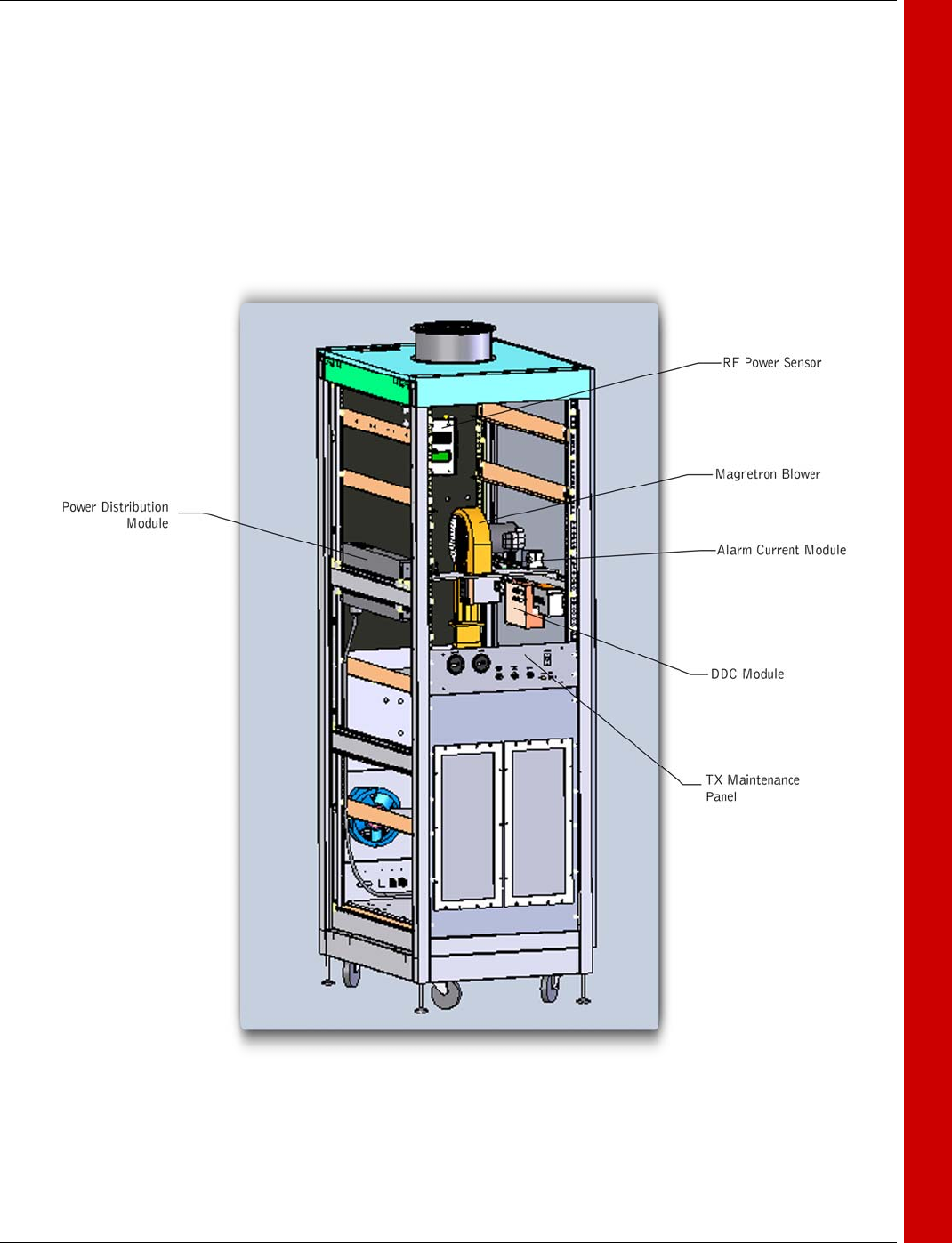
The base transmitter 1A1, is the foundation for the radar system and foundation con-
sists of the necessary power distribution, cooling, system control, and various other mod-
ules that provide the transmitter with the necessary items for proper operation. The base
transmitter is not frequency or power determinate, rather the base transmitter provides the
infrastructure to other modules. For more detail, reference schematic book Volume 3.
Numerous options exist within the base transmitter; refer to the family tree for your con-
figuration.
The Base Transmitter serves as host for the specific modulator and waveguide mod-
ules detailed in Chapter 2 to operate within various radar bands:
S-Band 2700 – 3000MHz.
C-Band 5200 – 5900MHz.
X-Band 8500 – 9600MHz.
The Base Transmitter consists of the following major functional areas:
AC & DC Power.
Power Distribution Unit (1A1A2)
System Power Supply (1A1PS1)
Power Distribution Block (1A1A4)
Cooling.
Magnetron Blower Assembly (1A1A6)
Alarm Current Monitor (1A1A11)
Temperature Sensors (TEMP 1, TEMP 2)
Control and Monitoring.
Distributed Data Collection Module (1A1A5)
Dual RF Power Sensor (1A1A7)
Interface.
Transmitter Maintenance Panel (1A1A9)
Transmitter I/O Panel (1A1A10)
Please see the next page for location of these modules within the base transmitter cabinet.
GENERAL INFORMATION
ISSUE/REVISION DATE: 12 March 2007 TECHNICAL MANUAL
CHAPTER 2 BASE TRANSMITTER (MAGNETRON)
ISO 9001:2000 PROPRIETARY
Base Transmitter (Magnetron) 2-4 ENTERPRISE ELECTRONICS CORPORATION
GENERAL INFORMATION
ISSUE/REVISION DATE: 12 March 2007 TECHNICAL MANUAL
CHAPTER 2 BASE TRANSMITTER (MAGNETRON)
ISO 9001:2000 PROPRIETARY
Base Transmitter (Magnetron) 2-5 ENTERPRISE ELECTRONICS CORPORATION
GENERAL INFORMATION
Temperature Sensor
Temperature Sensor
ISSUE/REVISION DATE: 12 March 2007 TECHNICAL MANUAL
CHAPTER 2 BASE TRANSMITTER (MAGNETRON)
ISO 9001:2000 PROPRIETARY
Base Transmitter (Magnetron) 2-6 ENTERPRISE ELECTRONICS CORPORATION
GENERAL INFORMATION

ISSUE/REVISION DATE: 12 March 2007 TECHNICAL MANUAL
CHAPTER 2 BASE TRANSMITTER (MAGNETRON)
ISO 9001:2000 PROPRIETARY
Base Transmitter (Magnetron) 2-7 ENTERPRISE ELECTRONICS CORPORATION
The power distribution module accepts the incoming Mains AC from the transmitter IO
panel, and provides a convenient central point of distribution. The module also contains
filtering circuitry to reduce EMI. This module accepts standard IEC-C13 and C19 plugs.
Each of the various modules within the base transmitter plug into this distribution unit
POWER DISTRIBUTION MODULE
ISSUE/REVISION DATE: 12 March 2007 TECHNICAL MANUAL
CHAPTER 2 BASE TRANSMITTER (MAGNETRON)
ISO 9001:2000 PROPRIETARY
Base Transmitter (Magnetron) 2-8 ENTERPRISE ELECTRONICS CORPORATION
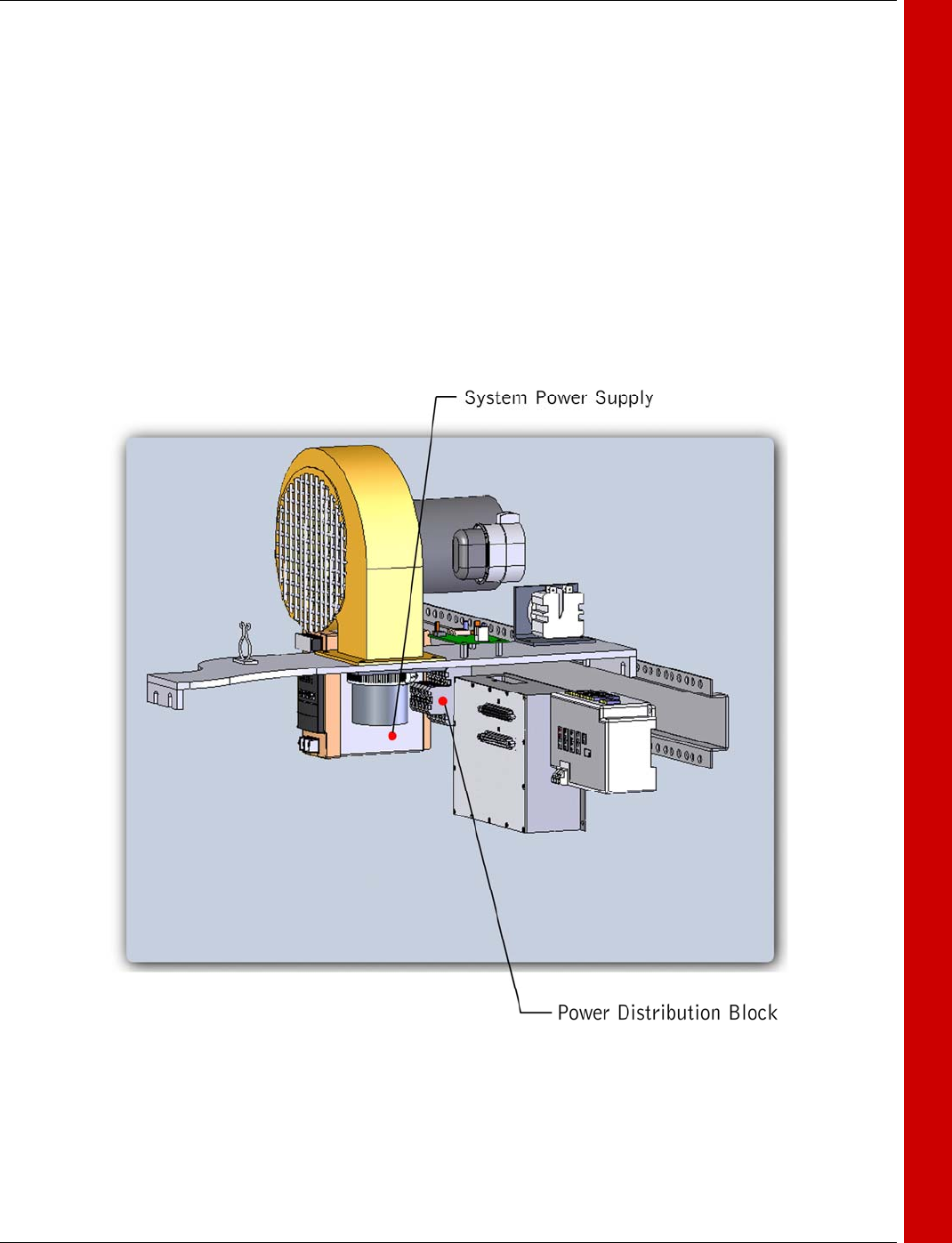
The system power supply is a +24VDC 120W
supply capable of providing the source for the
base transmitter unit. This supply is a high effi-
ciency switching supply with LED indication of
Voltage and current for ease of maintenance.
The supply is DIN rail mounted and has covers
protecting the AC Mains input and DC output.
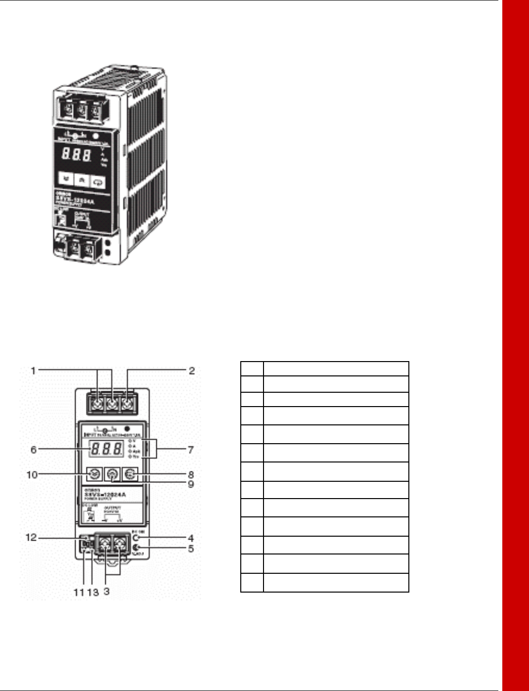
The following illustrates the basic features of this
supply:
1 AC Input terminals
2 Chassis ground terminal
3 DC output terminal
4 Output Indicator LED
5 Output Voltage adjust potentiometer
6 Main LED Display
7 LED Display Mode
8 Display Mode Key
9 Mode Up Key
10 Mode Down Key
11 Alarm Output terminal
12 Maintenance forecast terminal
13 Common for terminals
SYSTEM POWER SUPPLY

ISSUE/REVISION DATE: 12 March 2007 TECHNICAL MANUAL
CHAPTER 2 BASE TRANSMITTER (MAGNETRON)
ISO 9001:2000 PROPRIETARY
Base Transmitter (Magnetron) 2-9 ENTERPRISE ELECTRONICS CORPORATION
This DIN rail distribution buss is comprised of 6 individual modules connected by a com-
mon buss. This distributes both +24VDC and Ground. The terminals are recessed to
minimize the risk of short circuit due to foreign debris. All the contacts are properly coated
to reduce the risk of corrosion, and to operate without vibration, which could cause individ-
ual contacts to loosen. The unit is an industry standard method for proper distribution of
low Voltages. No periodic maintenance is required.
POWER DISTRIBUTION BLOCK

ISSUE/REVISION DATE: 12 March 2007 TECHNICAL MANUAL
CHAPTER 2 BASE TRANSMITTER (MAGNETRON)
ISO 9001:2000 PROPRIETARY
Base Transmitter (Magnetron) 2-10 ENTERPRISE ELECTRONICS CORPORATION
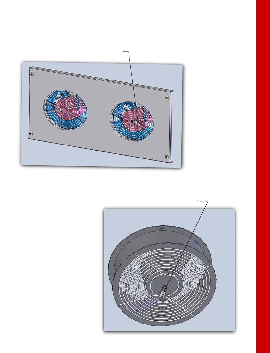
MAGNETRON BLOWER ASSEMBLY
The Magnetron blower assembly is the typical cooling system for the Magnetron tube.
Pictured above is the assembly with the hose and end-bell for use with the EEC Magne-
tron tubes. Each Magnetron tube type uses a different hose and end-bell arrangement but
is similar to the one pictured. A screen shroud is placed over the blower inlet to keep an
object from striking the spinning rotor. The blower is capable of moving approximately
250CFM at 1” of backpressure ensuring maximum cooling of the Magnetron tube
End Bell
Hose
Current Motor
Blower
ISSUE/REVISION DATE: 12 March 2007 TECHNICAL MANUAL
CHAPTER 2 BASE TRANSMITTER (MAGNETRON)
ISO 9001:2000 PROPRIETARY
Base Transmitter (Magnetron) 2-11 ENTERPRISE ELECTRONICS CORPORATION
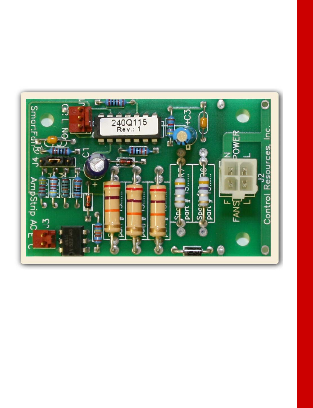
ALARM CURRENT MONITOR
Pictured above is the Alarm current sensor and alarm circuit board mounted on the Mag-
netron Blower Assembly. This module monitors the Magnetron blower for proper opera-
tion via current flow. If the current drops below a pre-set limit due to either motor failure or
other faults, the alarm circuit initiates a controlled shutdown of the transmitter thus pre-
venting damage of critical components. There are no adjustments or other periodic main-
tenance required.
ISSUE/REVISION DATE: 12 March 2007 TECHNICAL MANUAL
CHAPTER 2 BASE TRANSMITTER (MAGNETRON)
ISO 9001:2000 PROPRIETARY
Base Transmitter (Magnetron) 2-12 ENTERPRISE ELECTRONICS CORPORATION
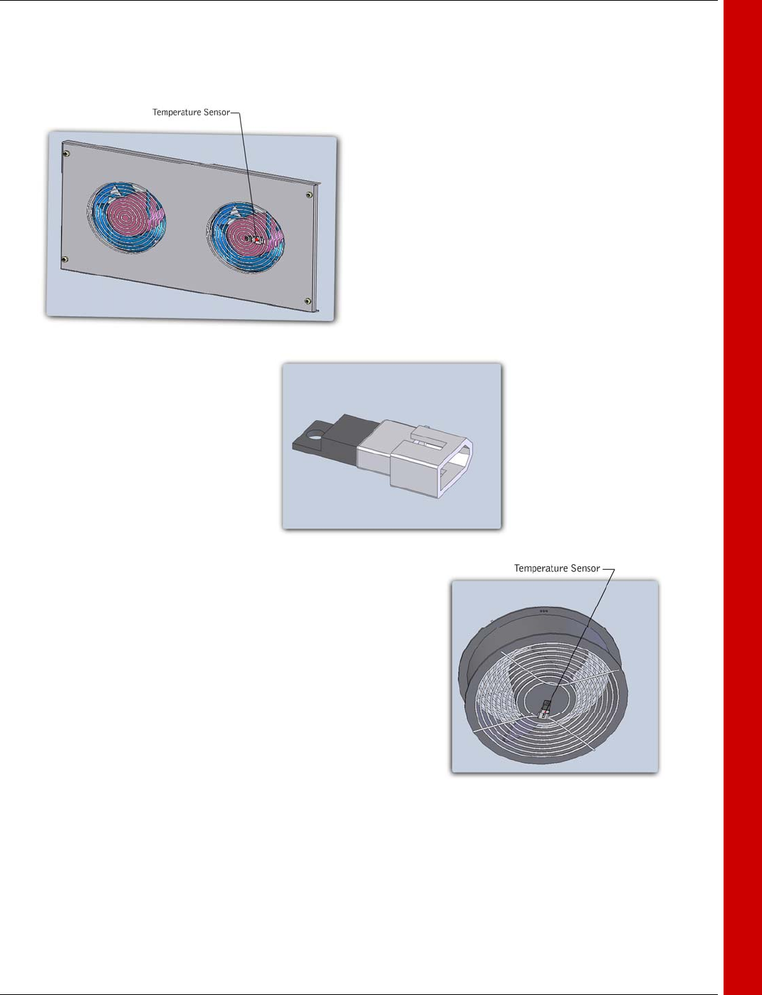
TEMPERATURE SENSORS
The temperature sensors used in the base transmitter unit are precision semi-conductor
temperature to Voltage converters. Additional circuitry is provided to compensate for ca-
ble length and to eliminate pulse noise. Both temperature sensors are fed to the DDC
module and the information is used both for BITE data and for transmitter monitoring .
ISSUE/REVISION DATE: 12 March 2007 TECHNICAL MANUAL
CHAPTER 2 BASE TRANSMITTER (MAGNETRON)
ISO 9001:2000 PROPRIETARY
Base Transmitter (Magnetron) 2-13 ENTERPRISE ELECTRONICS CORPORATION
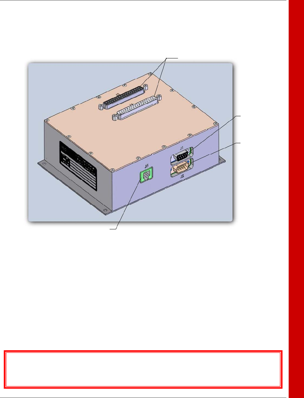
DISTRIBUTED DATA COLLECTION MODULE
The Distributed Data Collection (DDC) module is an Ethernet, CAN, or serial RS232 con-
trolled device that collects both analog and digital data, as well as controls relays. It out-
puts TTL signals under processor control. For general information please refer to EEC
Publication DDC-ICD and Users manual. For further information refer to the Personality
Addendum in the DDC Users Manual. The DDC module controls the base transmitter,
Solid State modulator systems, and provides control and monitoring of the temperatures.
The DDC also acts as the “gateway” for the Ethernet data stream, providing one compo-
nent that is the primary data collector and disseminator easing interface programming.
The Distributed Data Collection Module (DDC) Interface Control Document (ICD) provides textual detail of
the Distributed Data Collection Module (DDC)
I/O Ports
RS232
Power
Ethernet
ISSUE/REVISION DATE: 12 March 2007 TECHNICAL MANUAL
CHAPTER 2 BASE TRANSMITTER (MAGNETRON)
ISO 9001:2000 PROPRIETARY
Base Transmitter (Magnetron) 2-14 ENTERPRISE ELECTRONICS CORPORATION
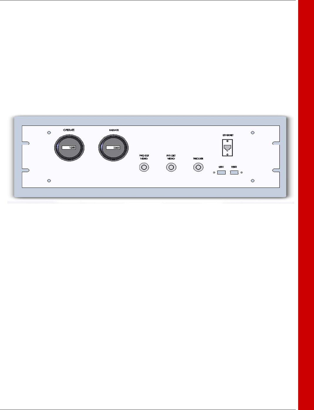
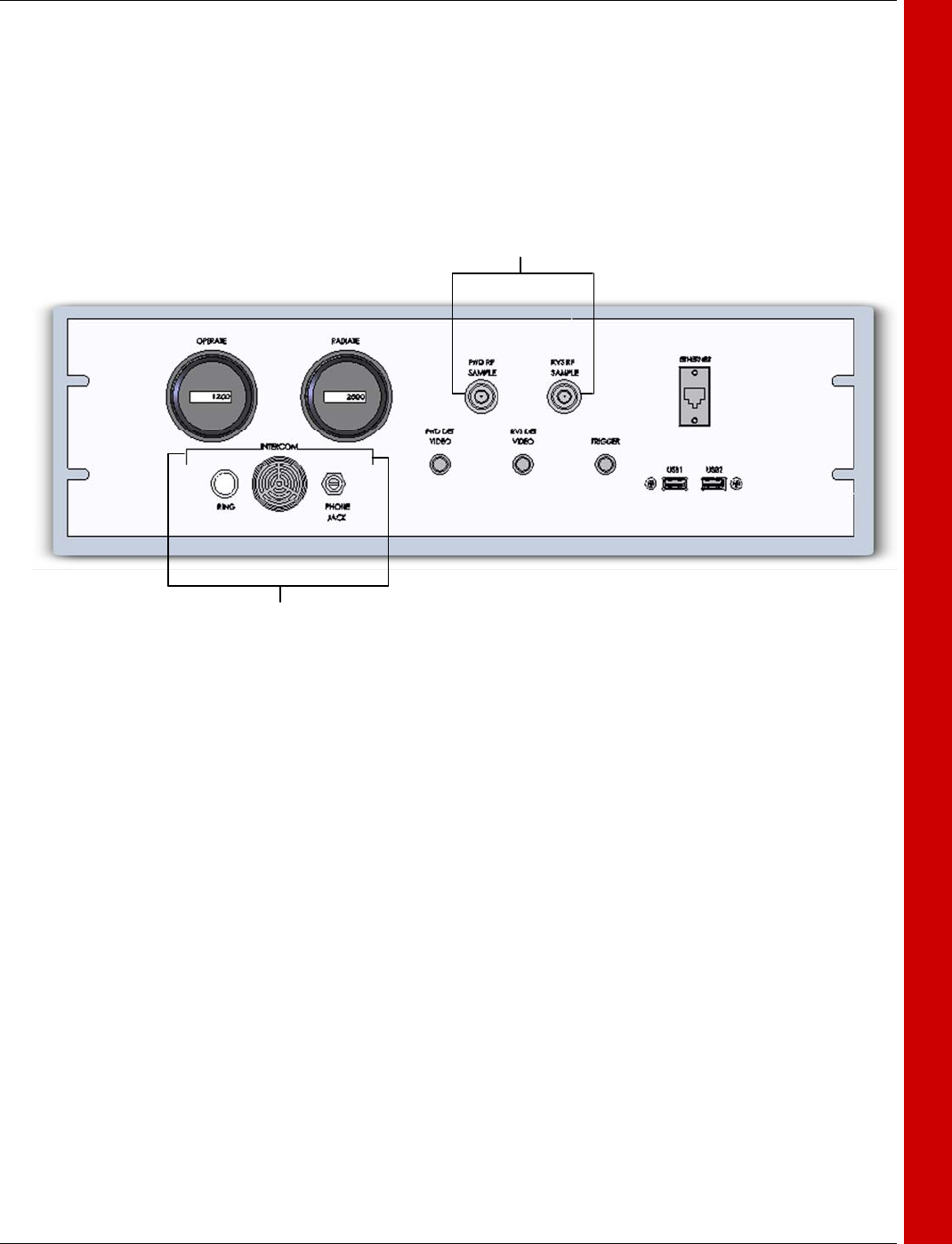
TRANSMITTER MAINTENANCE PANEL
Two different options for the transmitter maintenance panel exist; one incorporates a ped-
estal intercom function, and the other doesn't. Both configurations will be shown in this
document. Please refer to the FAMILY TREE for your specific unit.
The functions of this panel, which are common to both configurations, are run-time meter
displays, forward and reverse detected RF, trigger output, Ethernet interface, and USB 2.0
connectors for the optional touch screen computer. The panel is shown below.
• Operate Time Meter – Provides visual display of the hours of operation of the base
transmitter unit. This display is typically used to determine the hours of operation of the
Magnetron tube filaments.
• Radiate Time Meter – Display of hours the unit is in transmit operation.
• Trigger Test Jack – Used to trigger external test equipment by the system trigger gen-
erated in the base transmitter unit. This trigger is +5VDC positive going.
• Forward Detected RF – Connect to an oscilloscope to view the detected pulse of the
transmitter. The oscilloscope should have a bandwidth limit set at around 20MHz, or an
external low-pass filter with a cutoff of approximately 20MHz should be used for optimum
results. For Indication only. See Chapter 6 Maintenance section for Pulse Width Meas-
urement.
• Reverse Detected RF – Connect to an oscilloscope to view the detected pulse of the
transmitter. The oscilloscope should have a bandwidth limit set at around 20MHz, or an
external low-pass filter with a cutoff of approximately 20MHz should be used for optimum
results. See Chapter 6 Maintenance section for Pulse Width Measurement.
• Ethernet Port – Use for direct Ethernet connection to the base transmitter hub. An
external computer with optional EEC software can be connected to this port for transmitter
control during maintenance if the optional touch screen interface is not utilized.
USB 1 and USB 2 Ports – These ports are used only with the optional touch screen op-
tion and allows a mouse and keyboard to be connected. These are not required for regu-
lar use of the touch screen, though the user may be more comfortable with this method of
control.
ISSUE/REVISION DATE: 12 March 2007 TECHNICAL MANUAL
CHAPTER 2 BASE TRANSMITTER (MAGNETRON)
ISO 9001:2000 PROPRIETARY
Base Transmitter (Magnetron) 2-15 ENTERPRISE ELECTRONICS CORPORATION
TRANSMITTER MAINTENANCE PANEL
The optional pedestal intercom incorporates all the functions described above, and adds a
headphone jack, push to alert button, a sonic alert device, and RF sample ports for for-
ward and reverse power.
RF Sample Ports
Pedestal Intercom
ISSUE/REVISION DATE: 12 March 2007 TECHNICAL MANUAL
CHAPTER 2 BASE TRANSMITTER (MAGNETRON)
ISO 9001:2000 PROPRIETARY
Base Transmitter (Magnetron) 2-16 ENTERPRISE ELECTRONICS CORPORATION
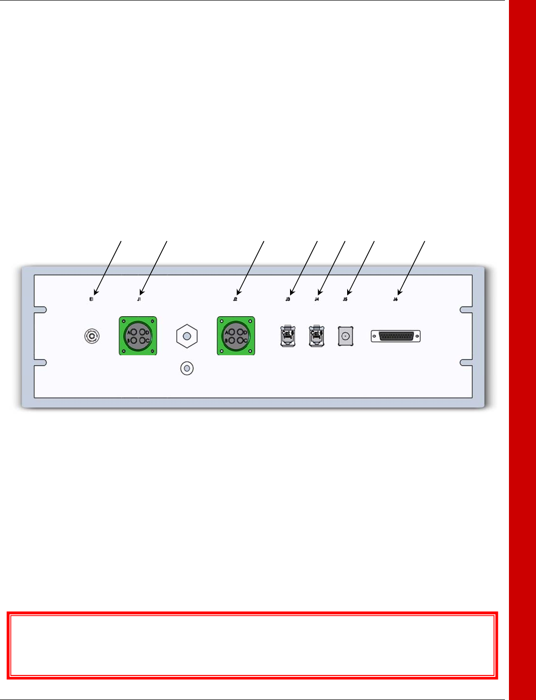
TRANSMITTER I/O PANEL
The transmitter I/O panel is the main interface point between the base transmitter, the ex-
ternal communication network, and pedestal equipment. For full details concerning the
signal characteristics of the interface panel, please refer to EEC Publication BASE
TRANSMITTER I/O ICD. The various connectors provided perform the following func-
tions.
• E1 – Chassis Ground
• J1 – AC Mains Input
• J2 – Unassigned
• J3 – J5 – Ethernet Communications
• J6 – Auxiliary monitoring connector
The Base Transmitter I/O Interface Control Document (ICD) provides textual detail of the Base Transmit-
ter I/O Modulator Assembly.
E1 J1 J2 J3 J4 J5 J6
ISSUE/REVISION DATE: 12 March 2007 TECHNICAL MANUAL
CHAPTER 2 BASE TRANSMITTER (MAGNETRON)
ISO 9001:2000 PROPRIETARY
Base Transmitter (Magnetron) 2-17 ENTERPRISE ELECTRONICS CORPORATION
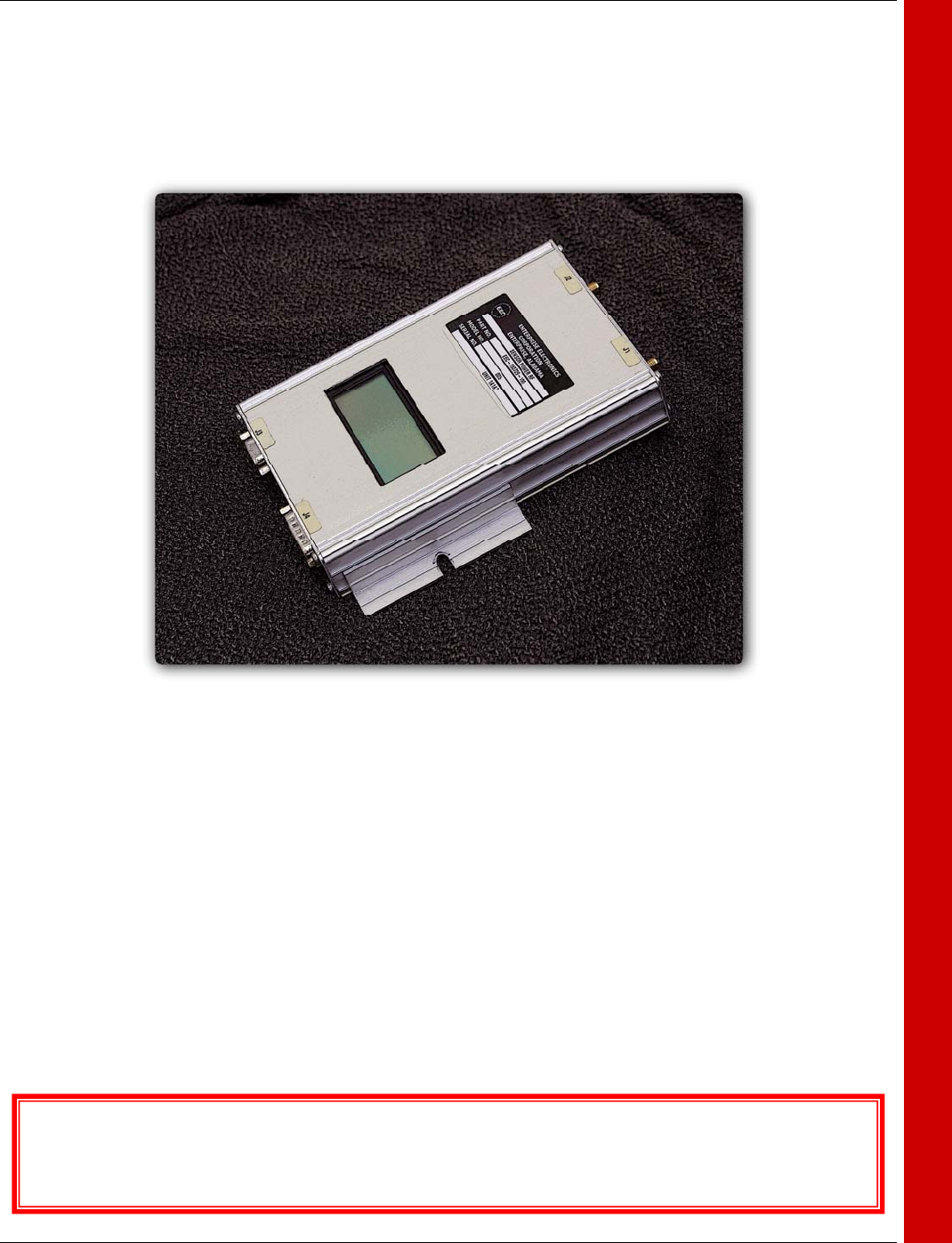
TRANSMITTER SUPPLEMENTAL
The Dual Port Power Sensor provides a real time analysis of the transmitted pulse and re-
verse power. Measuring both forward and reflected power from the waveguide assembly
bi-directional coupler allows for indication of the transmitted pulse and the reflected en-
ergy. Since reflected energy is also comprised of weather information, the reverse energy
is only measured during the transmitted pulse width. If a problem exists in the waveguide,
from the transmitter to the feed-horn, this reflected energy will be sensed, and depending
on the measured VSWR in the power monitor, the transmitter can be configured to shut-
down until the problem is resolved. An LCD display on the front of the power monitor
gives readouts of forward power, reverse power, both in dBm and in KiloWatts. The infor-
mation displayed on the power monitor is also fed to the DDC module for incorporation
into the BITE data stream for remote viewing. The power moniter can measure power of
RF pulses that are at least 0.4µs in width. For complete information about the various
modes of operation and in setting the user parameters please refer to EEC Publications;
Dual Port Power Monitor User Manual, and Dual Port Power Monitor ICD.
The Dual Port Power Sensor Interface Control Document (ICD) provides textual detail of the Dual RF Power
Sensor
Dual Port Power Sensor