Ericsson Wi Fi 20000001 BEL20000 2.4GHz WLAN Radio Module User Manual BelAir200 Installation Guide
Ericsson Wi-Fi BEL20000 2.4GHz WLAN Radio Module BelAir200 Installation Guide
Contents
- 1. Manual
- 2. BelAir200 Installation Guide
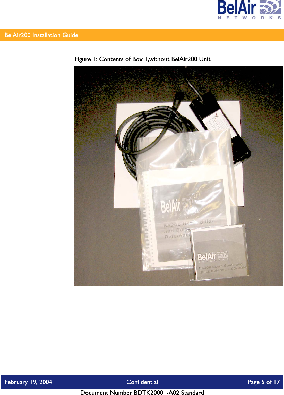
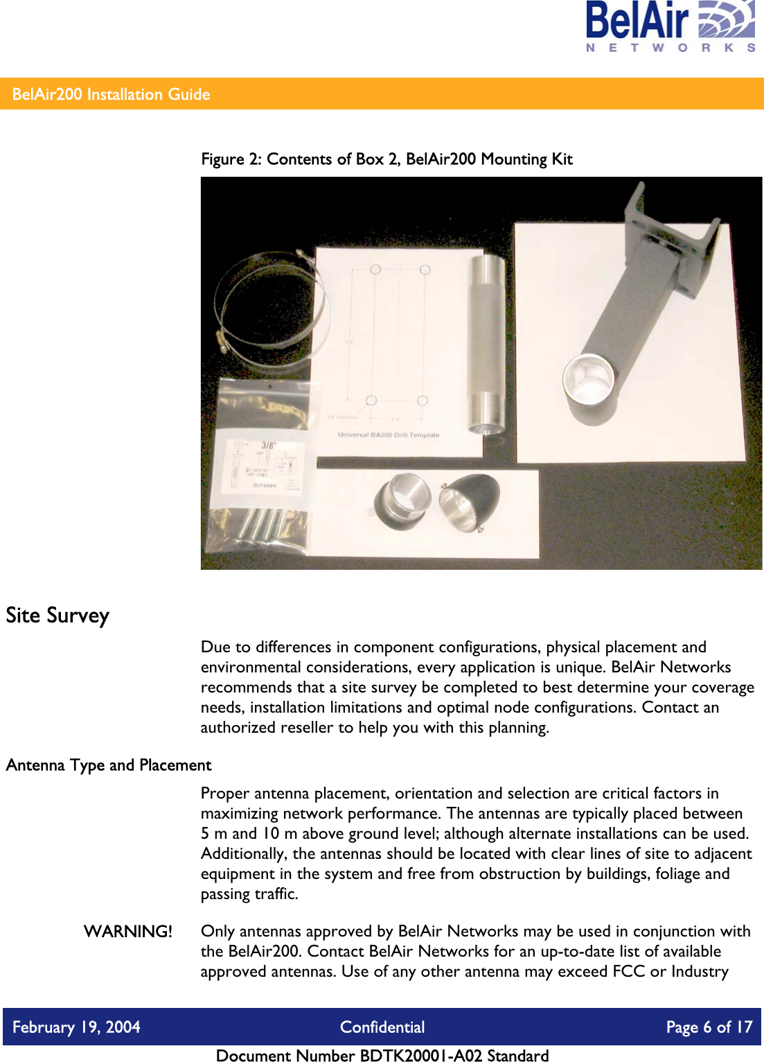
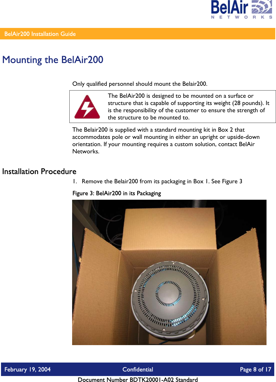
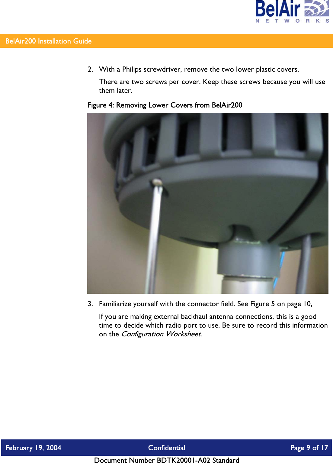
BelAir200 Installation Guide