Ericsson Wi Fi 20000001 BEL20000 2.4GHz WLAN Radio Module User Manual BelAir200 Installation Guide
Ericsson Wi-Fi BEL20000 2.4GHz WLAN Radio Module BelAir200 Installation Guide
Contents
- 1. Manual
- 2. BelAir200 Installation Guide
BelAir200 Installation Guide

BelAir200 General Availability
BelAir200
Installation Guide
Document Date: February 19, 2004
Document Number: BDTK20001-A02
Document Status: Standard
Security Status: Confidential
Customer Support: 613-254-7070
support@belairnetworks.com
© Copyright 2004 by BelAir Networks.
The information contained in this document is confidential and proprietary to BelAir Networks. Errors and Omissions Excepted.
Specifications may be subject to change.
Page 1 of 17

BelAir200 Installation Guide
Contents
About this Document.................................................................................. 2
Introduction ................................................................................................... 3
Mounting the BelAir200.............................................................................. 8
Regulatory Statements ..............................................................................13
Detailed Table of Contents......................................................................15
About this Document
This guide provides the information you need to physically install the
BelAir200.
Related Documentation
The following titles are BelAir reference documents:
•
BelAir200 Building Coverage Deployment Guidelines
•
BelAir200 User Guide
February 19, 2004 Confidential Page 2 of 17
Document Number BDTK20001-A02 Standard

BelAir200 Installation Guide
Introduction
BelAir Networks recommends that you prepare for the installation of your
Belair200 as follows:
1. Verify the contents of your shipping container. Be sure to note any
external carton damage with your shipper to facilitate any future warranty
claims. See the section “Shipping Contents” on page 4.
2. Fill out the included
Configuration Worksheet
to record the important
installation and network configuration settings.
3. Analyze your site to determine the optimum mounting location. To assist
you, refer to:
— the section “Site Survey” on page 6
— the
BelAir200 Building Coverage Deployment Guidelines
— your authorized reseller
4. Mount the Belair200 by following the steps in the procedure the section
“Mounting the BelAir200” on page 8.
5. Configure the BelAir200 for operation. Refer to the
BelAir200 User Guide.
6. Verify proper operation of the Belair200.
WARNING! Only personnel qualified by BelAir Networks or by one of its authorized
resellers or channel partners should install the BelAir200.
WARNING! This entire document, including the regulatory statements section, should be
read before attempting to install or operate the BelAir200.
February 19, 2004 Confidential Page 3 of 17
Document Number BDTK20001-A02 Standard

BelAir200 Installation Guide
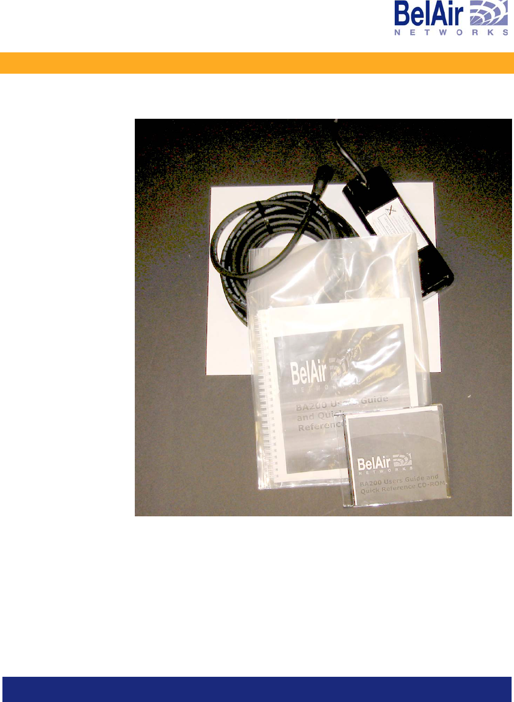
Shipping Contents
Table 1 describes how the standard BelAir200 items are packaged for shipping.
Table 1: BelAir200 Shipping
Box Contents
1 (of 2)
See Figure 1 on page 5.
BelAir200
AC mains power pigtail
Quick Configuration Guide Card
User Guide on CD-ROM
battery unit (if ordered)
2 (of 2)
See Figure 2 on page 6.
universal mounting bracket
threaded nipple
lock nut
decorative finial
hardwall anchors (quantity of 4)
8-inch worm drive (jubilee) clamp (quantity of 2)
drill template
February 19, 2004 Confidential Page 4 of 17
Document Number BDTK20001-A02 Standard
BelAir200 Installation Guide
Figure 1: Contents of Box 1,without BelAir200 Unit
February 19, 2004 Confidential Page 5 of 17
Document Number BDTK20001-A02 Standard

BelAir200 Installation Guide
Figure 2: Contents of Box 2, BelAir200 Mounting Kit
Site Survey
Due to differences in component configurations, physical placement and
environmental considerations, every application is unique. BelAir Networks
recommends that a site survey be completed to best determine your coverage
needs, installation limitations and optimal node configurations. Contact an
authorized reseller to help you with this planning.
Antenna Type and Placement
Proper antenna placement, orientation and selection are critical factors in
maximizing network performance. The antennas are typically placed between
5 m and 10 m above ground level; although alternate installations can be used.
Additionally, the antennas should be located with clear lines of site to adjacent
equipment in the system and free from obstruction by buildings, foliage and
passing traffic.
WARNING! Only antennas approved by BelAir Networks may be used in conjunction with
the BelAir200. Contact BelAir Networks for an up-to-date list of available
approved antennas. Use of any other antenna may exceed FCC or Industry
February 19, 2004 Confidential Page 6 of 17
Document Number BDTK20001-A02 Standard

BelAir200 Installation Guide
Canada regulatory requirements and void the operator’s right to operate the
radio equipment.
WARNING! Installers must ensure the BelAir200 is mounted in such a manner and in such
a location that access to the antennas by the general population is minimized.
Access to the antennas by the general population should be limited to greater
than 20 cm (8 inches) during normal operation.
February 19, 2004 Confidential Page 7 of 17
Document Number BDTK20001-A02 Standard

BelAir200 Installation Guide
Mounting the BelAir200
Only qualified personnel should mount the Belair200.
The BelAir200 is designed to be mounted on a surface or
structure that is capable of supporting its weight (28 pounds). It
is the responsibility of the customer to ensure the strength of
the structure to be mounted to.
The Belair200 is supplied with a standard mounting kit in Box 2 that
accommodates pole or wall mounting in either an upright or upside-down
orientation. If your mounting requires a custom solution, contact BelAir
Networks.
Installation Procedure
1. Remove the Belair200 from its packaging in Box 1. See Figure 3
Figure 3: BelAir200 in its Packaging
February 19, 2004 Confidential Page 8 of 17
Document Number BDTK20001-A02 Standard

BelAir200 Installation Guide
2. With a Philips screwdriver, remove the two lower plastic covers.
There are two screws per cover. Keep these screws because you will use
them later.
Figure 4: Removing Lower Covers from BelAir200
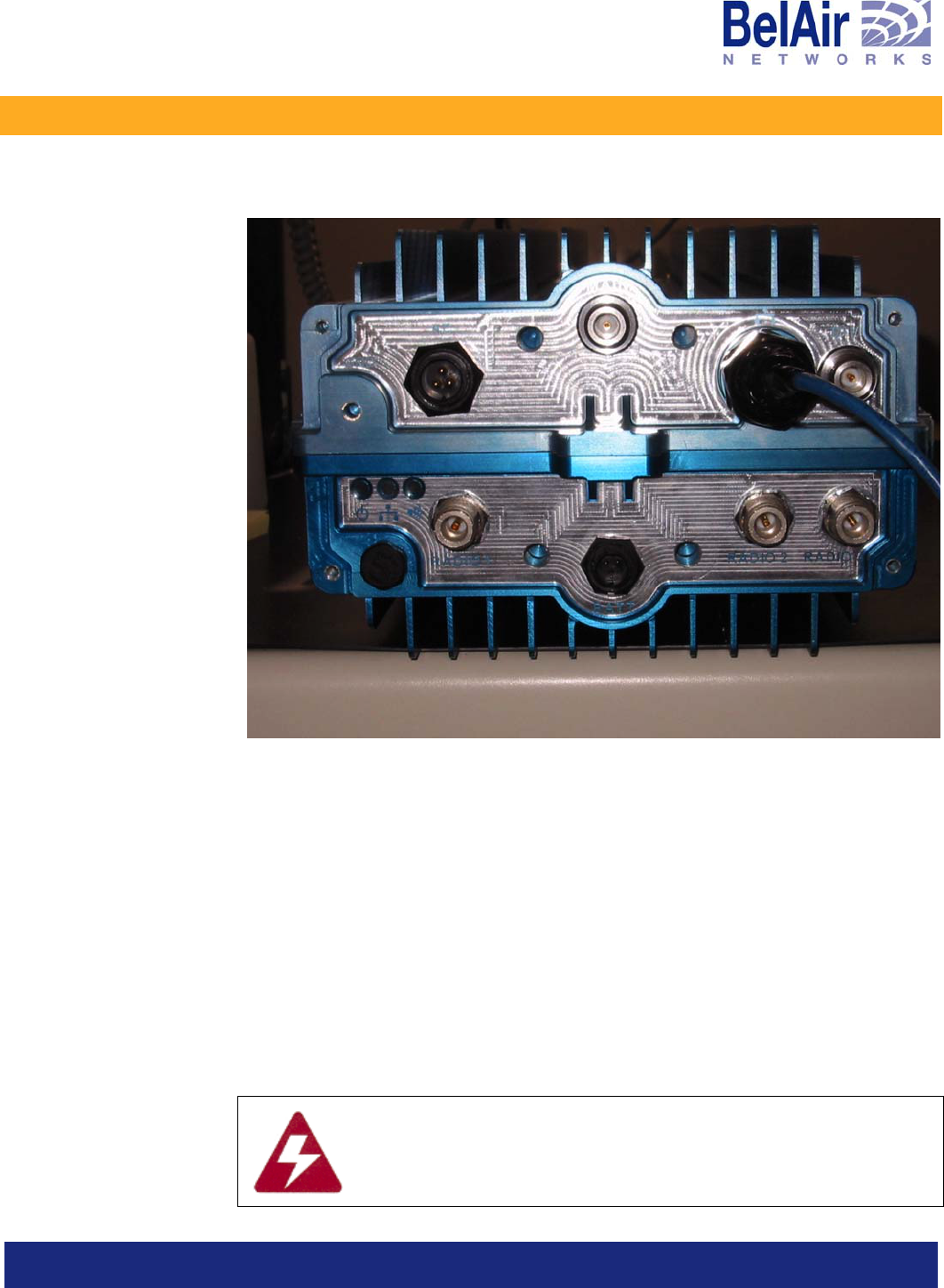
3. Familiarize yourself with the connector field. See Figure 5 on page 10,
If you are making external backhaul antenna connections, this is a good
time to decide which radio port to use. Be sure to record this information
on the
Configuration Worksheet
.
February 19, 2004 Confidential Page 9 of 17
Document Number BDTK20001-A02 Standard
BelAir200 Installation Guide
Figure 5: Connection Field
4. If you are using the optional battery pack, remove the battery access door
and insert the battery into its compartment. Install the battery door and
plug in the battery connector.
Note: Do not force the battery connector; it is “keyed”.
5. Remove the mounting kit from Box 2 and familiarize yourself with the
components.
6. If you are mounting to an aluminium, concrete or wood pole, skip to
step 9.
7. Locate the drill template and using an appropriate ladder or elevating
device, mark and drill the four mounting holes for the hardwall anchors.
Follow the instructions found in the bag of anchors.
Caution must be observed when working around high voltage
lines. Be sure to “Check Overhead” before ascending pole or
wall. Depending on your location, you may need the services of a
Certified Contractor to obtain access to utility poles.
February 19, 2004 Confidential Page 10 of 17
Document Number BDTK20001-A02 Standard

BelAir200 Installation Guide
8. Following the instructions included in the bag of anchors to mount the
universal bracket. Skip to step 10.
9. Using the supplied jubilee clamps, securely fasten the mounting bracket to
the utility pole.
Note: Certain jurisdictions may require the use of a certified contractor for
utility pole access. When mounting to wooden poles, you may be
required to install a bolt through the pole. These are not supplied
with the basic installation kit. Consult your reseller or local utility
operator for specific requirements.
10. Once the bracket has been securely mounted in its desired location, you
are ready to install the Belair200 Unit. See Figure 6.
Figure 6: BelAir200 Mounted on a Typical Pole, Ready for Pointing
February 19, 2004 Confidential Page 11 of 17
Document Number BDTK20001-A02 Standard

BelAir200 Installation Guide
11. Locate the threaded nipple, and screw this securely into the bottom of the
Belair200. A pipe wrench or similar tool can be used for this step.
12. Lift the unit to the desired mounting location and pass the threaded nipple
through the tube on the end of the mounting bracket.
— For an upside-down installation, be sure to screw the locking nut into
place. It is not important to tighten it fully at this point. The unit now
hangs from the mount.
Note: The Belair200 weighs 28 pounds, including battery. BelAir Networks
recommends using a safety tether while lifting the unit until the
locking nut is secured. A ring is supplied to attach the tether.
13. Rotate the Belair200 so the backhaul and access antennas point in the
desired direction. Consult you site survey or the installation diagram
supplied by your Reseller. Features are provided to provide a visual
indication of antenna direction.
14. Once the unit is pointed, firmly tighten the locking nut and install the
decorative finial.
15. Tighten the setscrews located on the mounting bracket.
16. Locate and install the AC power cable.
The cable is supplied as a pigtail that must be terminated at the front end
by a qualified electrician.
WARNING! Only use the AC cable supplied by BelAir Networks to attach to the unit. Use
of any other non-standard power cable may void regulatory requirements and
is strictly prohibited.
17. If this unit is to be directly connected with an Ethernet cable, connect the
Ethernet cable as follows:
a. Locate the sealing bland on the bottom of the unit.
b. Unscrew the gland and feed it over the Ethernet cable.
c. Plug the Ethernet connector into the port on the bottom of the unit.
d. Re-tighten the sealing gland.
18. Re-install the lower covers removed in step 2 using the appropriate
screws.
Your Belair200 is now ready to be configured. Refer to the
BelAir200 User
Guide
.
February 19, 2004 Confidential Page 12 of 17
Document Number BDTK20001-A02 Standard

BelAir200 Installation Guide
Regulatory Statements
Regulatory Information and Disclaimers
Installation and use of this device must be in strict accordance with the
instructions included in the user documentation provided with the product.
Any changes or modifications to this product not expressly approved by the
party responsible for compliance could void the user’s authority to operate
this equipment.
The manufacturer is not responsible for any interference to radio or television
equipment caused by unauthorized modification of this device, or attachment
of any antennas or equipment other than those specified by the manufacturer.
The manufacturer or its authorized resellers or distributors will assume no
liability for any damage or violation of government regulations arising from
failing to comply with these guidelines.
Manufacturer’s FCC Conformity Statement
This device complies with Part 15 of the FCC Rules.
Operation is subject to the following two conditions (1) this device may not
cause harmful interference, and (2) this device must accept any interference
received, including interference that may cause undesired operation.
FCC Interference Statement
This equipment has been tested and found to comply with the limits for a
Class B digital device, pursuant to Part 15 of the FCC Rules. These limits are
designed to provide reasonable protection against harmful interference in a
residential installation. This equipment generates, uses and can radiate radio
frequency energy and, if not installed and used in accordance with the
instructions, may cause harmful interference to radio communications.
However, there is no guarantee that interference will not occur in a particular
installation. If this equipment does cause harmful interference to radio or
television reception, which can be determined by turning the equipment off
and on, the user is encouraged to try to correct the interference by one or
more of the following measures:
• Reorient or relocate the receiving antenna.
• Increase the separation between the equipment and receiver.
February 19, 2004 Confidential Page 13 of 17
Document Number BDTK20001-A02 Standard

BelAir200 Installation Guide
• Connect the equipment into an outlet on a circuit different from that to
which the receiver is connected.
• Consult the dealer or an experienced radio/TV technician for help.
Manufacturer’s Industry Canada Conformity Statement
This device has been designed to operate with an antenna having a maximum
gain of 15 dBi. Antenna having a higher gain is strictly prohibited per
regulations of Industry Canada. The required antenna impedance is 50 ohms.
Operation is subject to the following two conditions: (1) this device may not
cause interference, and (2) this device must accept any interference, including
interference that may cause undesired operation of the device.
To reduce potential radio interference to other users, the antenna type and its
gain should be so chosen that the equivalent isotropically radiated power
(EIRP) is not more than that required for successful communication.
This Class B Digital apparatus meets all the requirements of the Canadian
Interference-Causing Equipment Regulations.
RF Exposure Statement
This Wireless LAN radio device has been evaluated under FCC Bulletin OET
65C and Health Canada Safety Code 6 and found to be compliant to the
requirements set forth in CFR 47 Sections 2.1091, 2.1093, and 15.247 (b) (4)
addressing RF exposure from radio frequency devices.
This device complies with FCC RF radiation exposure limits for an
uncontrolled environment. The radiated output power of this Wireless LAN
device is below the FCC radio frequency exposure limits. However, this device
should still be installed and used in such a manner that the potential for human
contact during normal operation is minimized. In order to comply with RF
exposure limits established in the ANSI C95.1 standard, this equipment should
be installed and operated at a minimum distance of 20 centimeters (8 inches)
between the radiator and a human body.
February 19, 2004 Confidential Page 14 of 17
Document Number BDTK20001-A02 Standard

BelAir200 Installation Guide
Detailed Table of Contents
About this Document.................................................................................. 2
Related Documentation .....................................................................................2
Introduction ................................................................................................... 3
Shipping Contents................................................................................................4
Site Survey.............................................................................................................6
Antenna Type and Placement..............................................................6
Mounting the BelAir200.............................................................................. 8
Installation Procedure.........................................................................................8
Regulatory Statements ..............................................................................13
Regulatory Information and Disclaimers ..................................................... 13
Manufacturer’s FCC Conformity Statement............................................... 13
FCC Interference Statement.......................................................................... 13
Manufacturer’s Industry Canada Conformity Statement ......................... 14
RF Exposure Statement................................................................................... 14
Detailed Table of Contents......................................................................15
List of Tables...................................................................................................... 15
List of Figures..................................................................................................... 15
List of Tables
Table 1: BelAir200 Shipping ............................................................................................4
List of Figures
Figure 1: Contents of Box 1,without BelAir200 Unit ...............................................5
Figure 2: Contents of Box 2, BelAir200 Mounting Kit..............................................6
February 19, 2004 Confidential Page 15 of 17
Document Number BDTK20001-A02 Standard

BelAir200 Installation Guide
Figure 3: BelAir200 in its Packaging...............................................................................8
Figure 4: Removing Lower Covers from BelAir200..................................................9
Figure 5: Connection Field ............................................................................................10
Figure 6: BelAir200 Mounted on a Typical Pole, Ready for Pointing...................11
February 19, 2004 Confidential Page 16 of 17
Document Number BDTK20001-A02 Standard

BelAir200 Installation Guide
760-918-5544
BelAir Networks U.S. East
11921 Freedom Drive
Suite 550
Reston, VA
USA
20190
703-736-8306
BelAir Networks U.S. West
1902 Wright Place
Suite 200
Carlsbad, CA
USA
92008
BelAir Networks Inc.
603 March Road
Kanata, Ontario
Canada
K2K 2M5
613-254-7070
Sales
sales@belairnetworks.com
General Information
Info@belairnetworks.com
February 19, 2004 Confidential Page 17 of 17
Document Number BDTK20001-A02 Standard