Ericsson Wi Fi 40005011 802.11n dual-band WIFI router User Manual BelAirOS User Guide
Ericsson Wi-Fi 802.11n dual-band WIFI router BelAirOS User Guide
UserManual.wiki
>
Ericsson Wi Fi
>
40005011 User Manual
>
User Manual
Contents
1.
User Manual
2.
User Manual - Power antenna installation note
3.
User Manual - Statements
User Manual
Navigation menu
Upload a User Manual
Namespaces
Wiki Guide
HTML
PDF
Info
Views
User Manual
Discussion / Help
Navigation
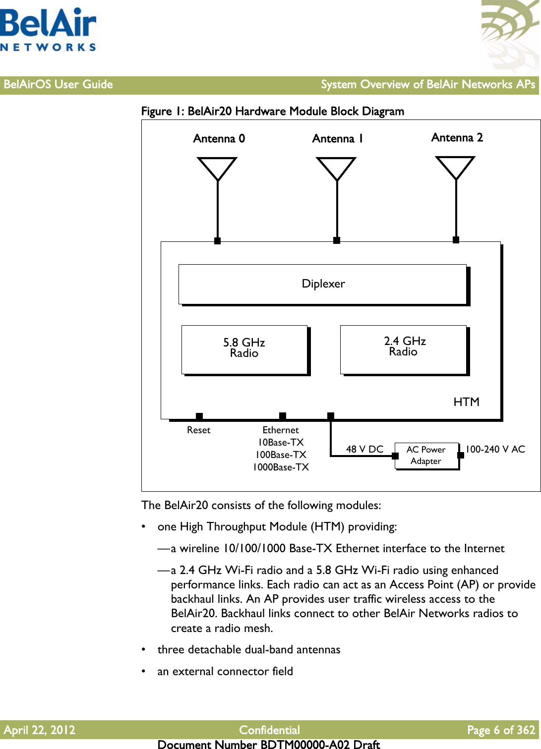
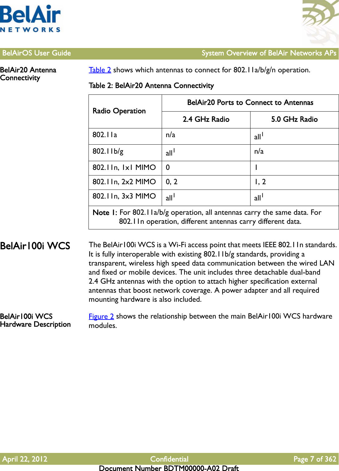
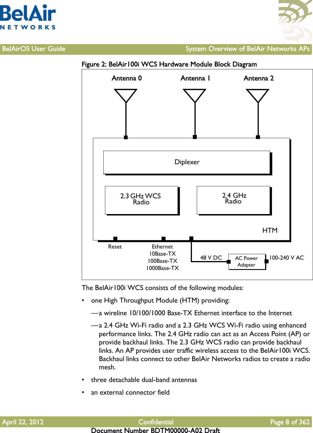
![BelAirOS User Guide About This Document April 22, 2012 Confidential Page 4 of 362Document Number BDTM00000-A02 DraftAbout This Document This document provides the information you need to install and configure BelAir Networks Wi-FI Access Points (APs) using the BelAirOS Operating System, and the procedures for using the AP Command Line Interface (CLI). This document may contain alternate references to APs. Ta b l e 1 shows possible synonyms to the product name. Typ o graph ic al ConventionsThis document uses the following typographical conventions:• Text in < > indicates a parameter required as input for a CLI command; for example, < IP address >• Text in [ ] indicates optional parameters for a CLI command.• Text in { } refers to a list of possible entries with | as the separator.• Parameters in ( ) indicate that at least one of the parameters must entered.Related Documentation The following titles are BelAir Networks reference documents:•BelAir20 Quick Install Guide•BelAir100i WCS Quick Install Guide•BelAir20E Quick Install Guide•BelAir20EO Quick Install Guide• WCSv1 Deployment and Installation Technical Bulletin•BelAir100SN Installation Guide•BelAir100SNE Installation Guide•BelAir100N Installation Guide•BelAir2100 Metrocell Installation Guide•BelAir2100 Metrocell Cellular Reference GuideTable 1: Product Name SynonymsProduct Name SynonymBelAir100N™ BA100NBelAir2100™ BA100PBelAir100SN™, BelAir100SNE™ BA100SBelAir20™, BelAir100i WCS, BelAir20E™, BelAir20EO™ BA20](https://usermanual.wiki/Ericsson-Wi-Fi/40005011.User-Manual/User-Guide-1698497-Page-4.png)
![BelAirOS User Guide Command Line Interface BasicsApril 22, 2012 Confidential Page 34 of 362Document Number BDTM00000-A02 Draft 8 h 9 hi10 ?11 show user12 cd /system13 show loads14 show sessions15 cd /16 cd interface/wifi-1-1/17 ?18 show19 show ssid table20 show statistics21 historySpecial CLI Keys Command CompletionYou can ask the CLI to complete a partially typed command or mode name by pressing the tab key. If the command or mode name cannot be completed unambiguously, the CLI presents you with a list of possible completions. For instance, entering:/system# show co{tab}produces the following output:Available commands :show communicationsshow config-download statusshow coordinatesshow country [detail]Execution of the Last Typed CommandYou may repeat the last command, by entering the ! key twice, followed by carriage return.Executing the Previous CommandsYou may browse through the command history by using the up and down arrow keys of a VT100 or compatible terminal. You can also execute a certain command from the command history by entering the ! key, followed by the command number (as displayed in the history command output) and carriage return.Help Command ??? [<command>]help [<command>]](https://usermanual.wiki/Ericsson-Wi-Fi/40005011.User-Manual/User-Guide-1698497-Page-34.png)
![BelAirOS User Guide Command Line Interface BasicsApril 22, 2012 Confidential Page 35 of 362Document Number BDTM00000-A02 DraftThese commands display:• a list of commands available in the current mode• help on a particular command available in the current mode• help on commands starting with the given keyword in the current modeEntering "??" is equivalent to entering "help".Available CommandsEntering ? displays the commands that apply to the currently accessed mode. For example:/mgmt# ?Available commands :adduser <user-name> -p <passwd> [ -d <default-mode>] [-g <grp-name>]deluser <user-name>moduser <user-name> [ -p <passwd>] [ -d <default-mode>] [-g <grp-name>]set authentication-login {local | radius <list>}set telnet {enabled|disabled}show authentication-loginshow telnet statusshow userEntering ?? or help displays the commands that apply to the currently accessed mode plus common commands that are available in all modes. For example:/mgmt# ??Available commands :adduser <user-name> -p <passwd> [ -d <default-mode>] [-g <grp-name>]deluser <user-name>moduser <user-name> [ -p <passwd>] [ -d <default-mode>] [-g <grp-name>]set authentication-login {local | radius <list>}set telnet {enabled|disabled}show authentication-loginshow telnet statusshow useralias [<replacement string> <token to be replaced>]cd <path>clear-screenconsole lockexithelp [ command ]historymode [<mode_name>]passwdping <ip addr> [-l <size>]run script <script file> [<output file>]versionwhoamiconfig-save [{active|backup} remoteip <server> remotefile <filename> [{tftp | ftp [user <username> password <password>]}]]config-restore remoteip <ipaddress> remotefile <filename> [{tftp | ftp [user <username> password <password>]}] [force]show date](https://usermanual.wiki/Ericsson-Wi-Fi/40005011.User-Manual/User-Guide-1698497-Page-35.png)
![BelAirOS User Guide Command Line Interface BasicsApril 22, 2012 Confidential Page 36 of 362Document Number BDTM00000-A02 Draftsu <username>Keyword HelpEntering ?? or help followed by a keyword displays all possible commands starting with that keyword. For example:/mgmt# ?? showAvailable commands :show authentication-login Description : show authentication login status and RADIUS servers configurationshow telnet status Description : shows the status of the telnet.show user Description : List all valid users, along with their permissible mode.show date Description : show current system date and timeHelp for a Specific CommandWhen help is needed for a specific command, enter ?? or help followed by the command within quotes. For example:/mgmt# help "adduser"Available commands :adduser <user-name> -p <passwd> [ -d <default-mode>] [-g <grp-name>] Description : Create a user.Help with AbbreviationsWhen an abbreviation is used in the help string, all matching commands are listed with the description. For example:/mgmt# ?? sAvailable commands :set authentication-login {local | radius <list>} Description : defines how login session will be authenticated.set telnet {enabled|disabled} Description : enable or disable CLI access via the telnet protocol.show authentication-login Description : show authentication login status and RADIUS servers configurationshow telnet status Description : shows the status of the telnet.show user Description : List all valid users, along with their permissible mode.show date Description : show current system date and timesu <username> Description : Substitute present user with the given user.](https://usermanual.wiki/Ericsson-Wi-Fi/40005011.User-Manual/User-Guide-1698497-Page-36.png)
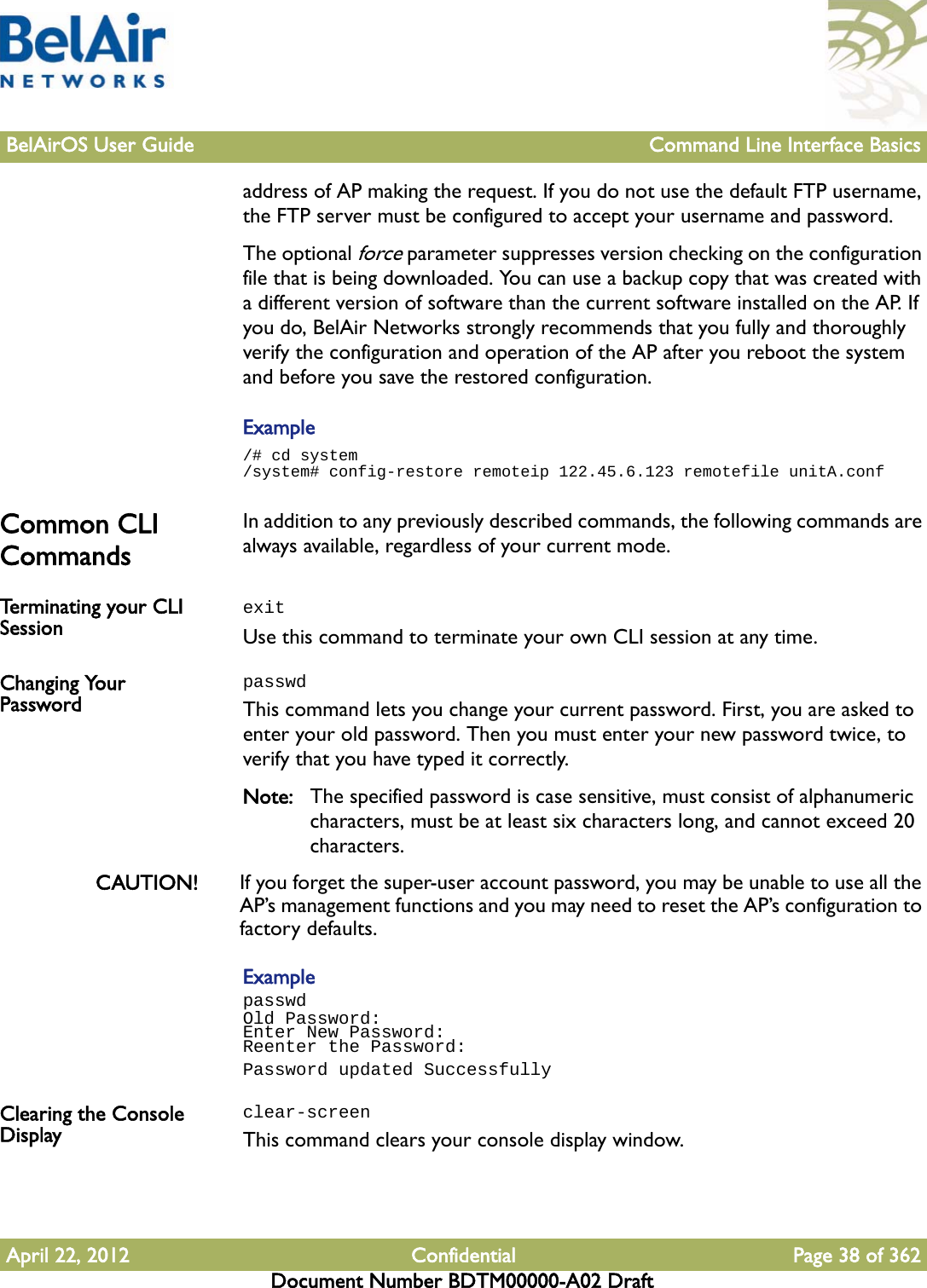
![BelAirOS User Guide Command Line Interface BasicsApril 22, 2012 Confidential Page 37 of 362Document Number BDTM00000-A02 DraftSaving your ChangesIf you change any settings from the system defaults, you must save those changes to the configuration database to make sure they are applied the next time the AP reboots. Similarly, you can restore the entire configuration database from a previously saved backup copy. Saving the Configuration Databaseconfig-save [{active|backup} remoteip <ipaddress> remotefile <filename> [{tftp|ftp [user <usrname> password <pword>]}]] This command allows you to save the current configuration of the entire AP. This includes all system, layer 2 and radio settings. When used without its optional parameters, the config-save command saves the configuration database for the active software load to persistent storage. The stored configuration is automatically applied at the next reboot.When used with its optional parameters, the config-save command also transfers the configuration database to a remote server. If active is specified, the config-save command saves the configuration database for the active software load to persistent storage and then transfers it to a remote server. If backup is specified, the configuration database for the active software load is not saved. Instead, the configuration database for the active software load that was saved previously to persistent storage, is transferred to a remote server.You can use either TFTP or FTP to communicate with the remote server. By default, the config-save command uses TFTP. If you specify FTP, you can also specify the username and password. The default FTP username is anonymous and the default FTP password is root@<nodeip>, where <nodeip> is the IP address of AP making the request. If you do not use the default FTP username, the FTP server must be configured to accept your username and password.Restoring the Configuration Databaseconfig-restore remoteip <ipaddress> remotefile <filename> [{tftp|ftp [user <usrname> password <pword>]}]] [force]This command transfers the configuration database from a remote server to the active software load in persistent storage. This allows you to restore the entire configuration database from a previously saved backup copy.Use the reboot command for the new configuration to take effect.You can use either TFTP or FTP to communicate with the remote server. By default, the config-restore command uses TFTP. If you specify FTP, you can also specify the user name and password. The default FTP user name is anonymous and the default FTP password is root@<nodeip>, where <nodeip> is the IP](https://usermanual.wiki/Ericsson-Wi-Fi/40005011.User-Manual/User-Guide-1698497-Page-37.png)
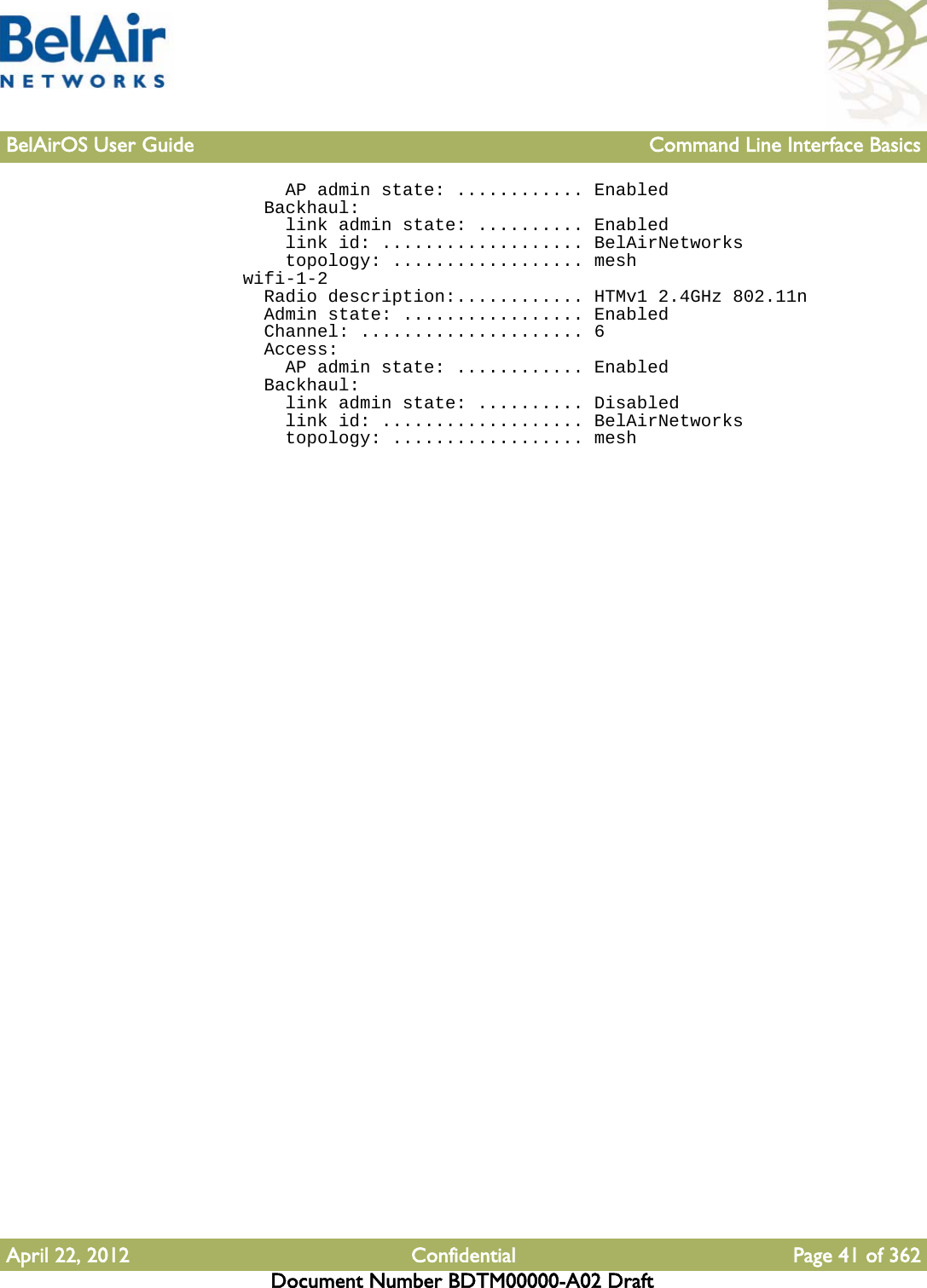
![BelAirOS User Guide Command Line Interface BasicsApril 22, 2012 Confidential Page 40 of 362Document Number BDTM00000-A02 Draft/# whoamiCurrent User is rootReplacing a Token by a Stringalias [<replacement string> <token to be replaced>]This command replaces the specified token by the given string. It is provided for customers writing scripts. See “Scripting Guidelines” on page 309.Example/# alias gu guest Pinging a Host or Switch ping <host> [-1 <size>]This command pings a host machine or switch using the host name or IP address.The following options are supported:-l size specifies the size of the ping request packets to be sent.ExamplesThe following example shows typical ping output:/# ping 10.1.1.100 -l 128PING 10.1.1.100 (10.1.1.100): 128 data bytes136 bytes from 10.1.1.100: icmp_seq=0 ttl=128 time=2.0 ms136 bytes from 10.1.1.100: icmp_seq=1 ttl=128 time=1.2 ms136 bytes from 10.1.1.100: icmp_seq=2 ttl=128 time=1.0 ms--- 10.1.1.100 ping statistics ---3 packets transmitted, 3 packets received, 0% packet lossround-trip min/avg/max = 1.0/1.4/2.0 msStarting a Telnet Session telnet <ip address> [<port_number>]This command lets you start a Telnet session to another machine, such as another AP, by specifying the IP address. By default t, Telnet uses port 23. You can also specify an alternate port number.Radio Configuration Summaryshow interface summaryThis command displays a summary of the configuration of all radio interfaces.ExampleThe following example shows a typical output for a BelAir20./# show interface summarywifi-1-1 Radio description:............ HTMv1 5GHz 802.11n Admin state: ................. Enabled Channel: ..................... 149 Access:](https://usermanual.wiki/Ericsson-Wi-Fi/40005011.User-Manual/User-Guide-1698497-Page-40.png)
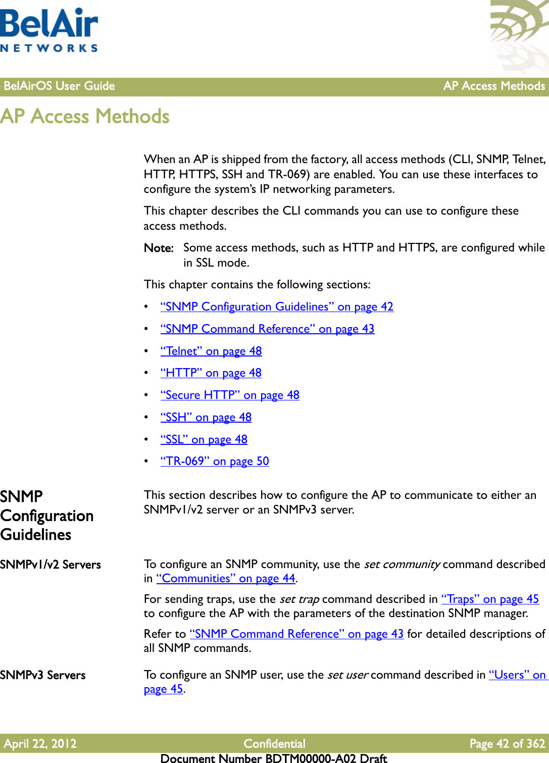
![BelAirOS User Guide AP Access MethodsApril 22, 2012 Confidential Page 43 of 362Document Number BDTM00000-A02 DraftFor sending notifications, use the set notify command described in “Notifications” on page 46 to configure the AP with the parameters of the destination SNMP manager.Refer to “SNMP Command Reference” on page 43 for detailed descriptions of all SNMP commands, including entities that need to be predefined.SNMP Naming Restrictions SNMP community names, user names, and notification names must not contain the following characters: —bar (|)—semicolon (;)—percent (%)—double quotation mark (“) SNMP Command ReferenceThe following sections show you how to configure SNMP functions.SNMP Agent /protocol/snmp/set snmp-agent {enabled | disabled}/protocol/snmp/show snmp-agentThe set snmp-agent command enables or disables SNMP access. SNMP Configuration /protocol/snmp/show config [{v2 | v3 | all}]Use the show config command to display the current SNMP configuration. Passwords are only displayed to users with root privileges. See “User Privilege Levels” on page 52 for details. Example 1/protocol/snmp# show config v2EngineId: 80003d9805000d67091448 Community configuration:------------------------Index Name IP Address Privilege----- ------------------ --------------- -----------1 public 0.0.0.0 ReadOnly2 private 10.1.1.70 ReadWrite Trap configuration:-------------------Index IP address Community Version](https://usermanual.wiki/Ericsson-Wi-Fi/40005011.User-Manual/User-Guide-1698497-Page-43.png)
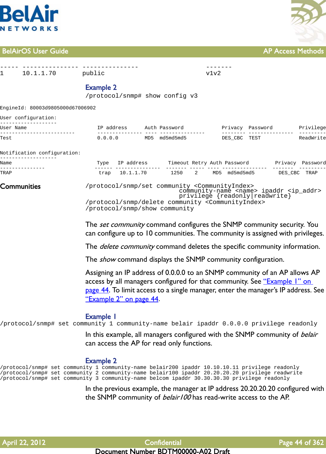
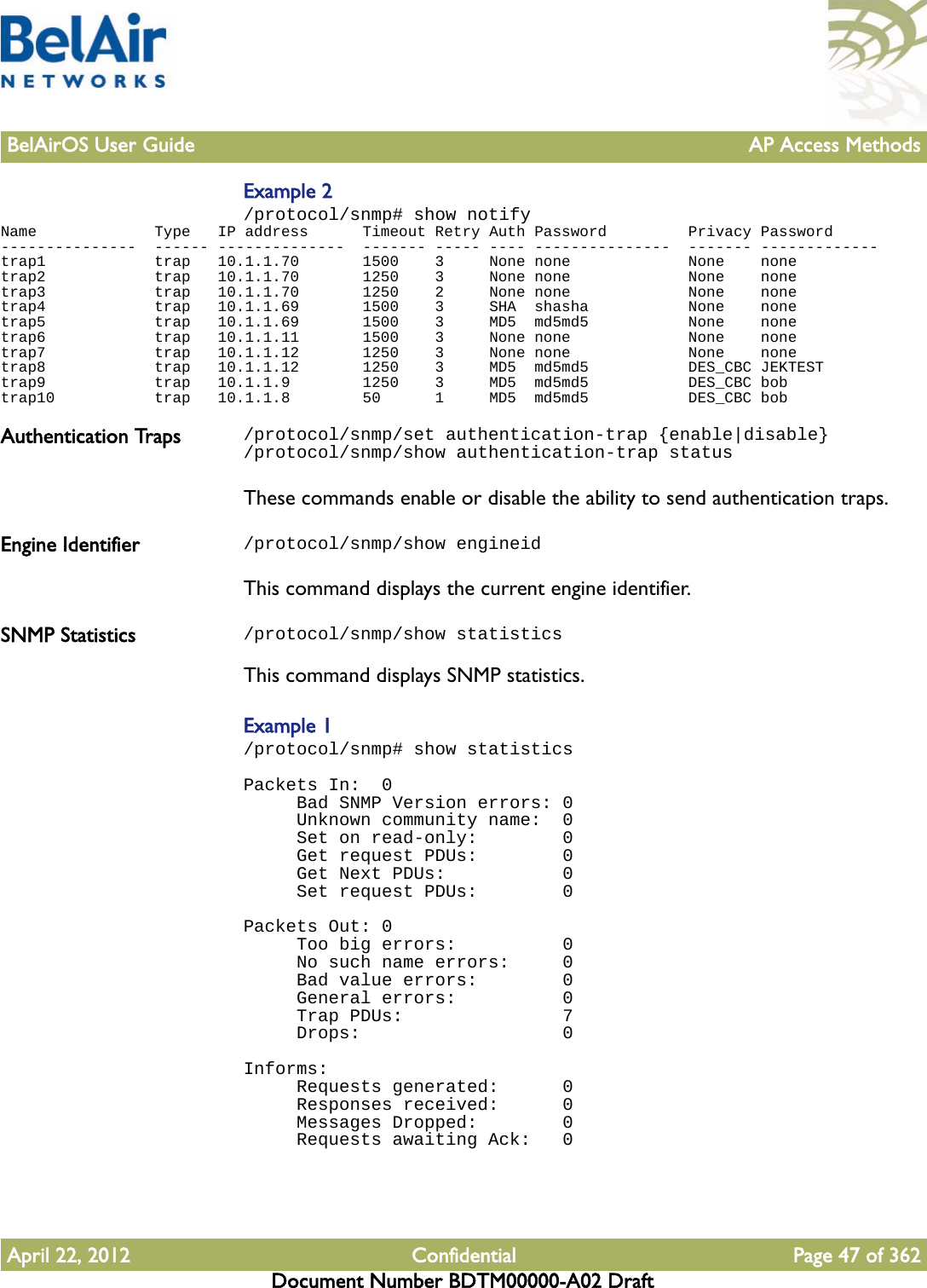
![BelAirOS User Guide AP Access MethodsApril 22, 2012 Confidential Page 45 of 362Document Number BDTM00000-A02 DraftExample 3/protocol/snmp# show communityIndex Name IP Address Privilege----- ------------------ --------------- -----------1 public 0.0.0.0 ReadOnly2 private 10.1.1.70 ReadWriteTrap s /protocol/snmp/set trap <index> mgr-addr <ip_addr> community <name> version {v1|v2|both}/protocol/snmp/delete trap <index>/protocol/snmp/show trapThe set trap command configures the parameters of the SNMPv2 trap manager. You can configure up to 10 traps.The delete trap command deletes the specified trap manager information.The show trap command displays the SNMPv2 trap manager configuration information. Example 1/protocol/snmp# set trap 1 mgr-addr 40.40.40.40 community bel1 version v1/protocol/snmp# set trap 2 mgr-addr 41.41.41.41 community bel2 version v2Example 2/protocol/snmp# show trapIndex IP address Community Version----- --------------- --------------- -------1 10.1.1.70 public v1v2Users /protocol/snmp/set user <UserName> ipaddr <IP_addr> access {readonly | readwrite} [auth {md5 | sha} <password> [priv-DES <passwd>]]/protocol/snmp/delete user <UserName>/protocol/snmp/show userThe set user command defines an SNMPv3 user. You can define up to 10 users, each with different authentication and privacy settings. The ipaddr parameter specifies the IP address associated with this user. The access parameter specifies the level of access granted to this user.The <password> parameter is the password required by the user to access SNMP data. A user must supply this password if using a MIB browser.The AP uses DES encryption to encrypt SNMP packets. The priv-DES parameter specifies the encryption key required to encrypt or decrypt the packet.](https://usermanual.wiki/Ericsson-Wi-Fi/40005011.User-Manual/User-Guide-1698497-Page-45.png)
![BelAirOS User Guide AP Access MethodsApril 22, 2012 Confidential Page 46 of 362Document Number BDTM00000-A02 DraftThe delete user command deletes the definition of the specified SNMP user.The show command displays the configured users. Passwords are only displayed to users with root privileges. See “User Privilege Levels” on page 52 for details.Example 1/protocol/snmp# set user v3md5 ipaddr 0.0.0.0 access readwrite auth md5 md5md5md5Example 2/protocol/snmp# show userUser Name IP address Auth Password Privacy Password Privilege-------------- --------------- ---- --------------- -------- ---------v3md5 0.0.0.0 MD5 md5md5md5 None none ReadWriteNotifications /protocol/snmp/set notify <NotifyName> type {Trap | Inform} ipaddr <IP_addr> [timeout <1-1500>] [retries <1-3>] [auth {md5 | sha} <password> [priv-DES <passwd>]]/protocol/snmp/delete notify <NotifyName>/protocol/snmp/show notifyThe set notify command enables notifications to be sent to an SNMPv3 manager for the specified notification name. You can configure up to 10 notification names.The ipaddr parameter specifies the IP address associated with this notification.The timeout parameter specifies how many seconds to wait for an acknowledgement before resending the SNMP packet. The retries parameter specifies the number of times to resend the SNMP before declaring a failure.The <password> parameter is the password associated with this notification.The AP uses DES encryption to encrypt SNMP packets. The priv-DES parameter specifies the encryption key required to encrypt or decrypt the packet.The delete notify command disables notifications from being sent for the specified notification name.The show notify command displays the current SNMP notify configuration. Passwords are only displayed to users with root privileges. See “User Privilege Levels” on page 52 for details.Example 1/protocol/snmp# set notify trap1 type trap ipaddr 10.1.1.70](https://usermanual.wiki/Ericsson-Wi-Fi/40005011.User-Manual/User-Guide-1698497-Page-46.png)
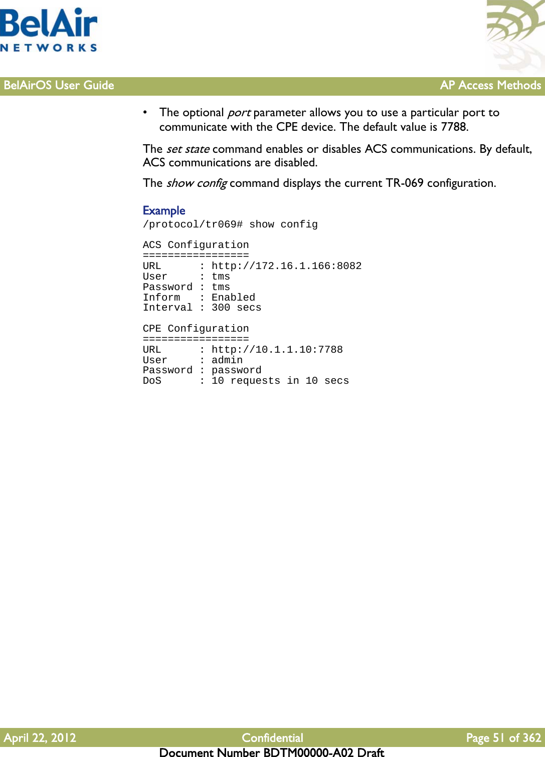
![BelAirOS User Guide AP Access MethodsApril 22, 2012 Confidential Page 50 of 362Document Number BDTM00000-A02 DraftExample/#cd ssl/ssl# ssl saveTR-069 TR-069 describes the CPE WAN Management Protocol (CWMP) required for communications between a CPE device, such as a BelAir Networks AP, and an Auto-configuration Server (ACS).This section describes how to configure the AP to communicate with an ACS.Only the following BelAir Networks APs support TR-069: BelAir20, BelAir100i WCS, BelAir100N, BelAir100SN, BelAir100SNE and BelAir2100.Configuring ACS Communications/protocol/tr069/set acs-configuration url <hostname> user <username> password <password>/protocol/tr069/set inform {enabled ([interval <seconds>]) |disabled}/protocol/tr069/set cpe-configuration url <hostname> user <username> password <password> [port <1024-65535>]/protocol/tr069/set dos-attack {requests <1-1000> interval <1-900>}/protocol/tr069/set state {enabled | disabled}/protocol/tr069/show configThe set acs-configuration command specifies the ACS to communicate with:• The url parameter specifies the host for the ACS. The default value is http://211.110.60.3:8080/TMS/acs.• The user parameter specifies the user name to login to the ACS. The default value is tmsadmin.• The password parameter specifies the password to login to the ACS. The default value is tmsadmin123.The set inform command specifies how often the AP sends inform messages to the ACS. The interval parameter ranges from 60 to 900 seconds. By default, inform messages are sent every 300 seconds.The set cpe-configuration command specifies the parameters by which the ACS can log into the CPE device, such as the BelAir Networks AP:• The url parameter specifies the DNS or IP address to reach the CPE device.• The user parameter specifies the user name to login to the CPE device. The default value is admin.• The password parameter specifies the password to login to the CPE device. The default value is password.](https://usermanual.wiki/Ericsson-Wi-Fi/40005011.User-Manual/User-Guide-1698497-Page-50.png)
![BelAirOS User Guide User and Session AdministrationApril 22, 2012 Confidential Page 52 of 362Document Number BDTM00000-A02 DraftUser and Session AdministrationThis chapter describes user administration functions with the following topics:•“User Privilege Levels” on page 52•“User Accounts” on page 55•“Configuring Authentication for User Accounts” on page 56•“CLI and Web Sessions” on page 58User Privilege LevelsUser accounts on an AP can be assigned the following three privilege levels:•An observer user can execute only the following commands:—most show commands—the help and ? commands—the passwd command—the clear-screen and exit commands—the cd and mode commands—the history command—the whoami command—the ping command•A normal user can execute any CLI command, except those reserved for the super-user.• The super-user can execute any CLI command. Table 5 on page 52 lists the CLI commands that are reserved for the super-user. Each AP can have any number of observer users and normal users, but only one super-user account, called root. Table 5: Super-user commands Common Commandsconfig-restore remoteip <ipaddress> remotefile <filename> [{tftp|ftp [user <usrname> password <pword>]}]] [force]](https://usermanual.wiki/Ericsson-Wi-Fi/40005011.User-Manual/User-Guide-1698497-Page-52.png)
![BelAirOS User Guide User and Session AdministrationApril 22, 2012 Confidential Page 53 of 362Document Number BDTM00000-A02 DraftMgmt Commandsadduser <user-name> -p <passwd> [-d <mode>] [-g <group>]deluser <user-name>moduser <user-name> [ -p <passwd>] [ -d <mode>] [-g <group>]show userset telnet {enabled|disabled}set authentication-login {local | radius <list>}show authentication-loginSystem Commandsset country <country_name> set global-session-timeout <period>terminate session <session_index>upgrade load remoteip <serverIPaddress> remotepath <serverSubDir> [{tftp|ftp [user <usrname> password <pword>]}]]cancel upgradereboot [{force}]commit loadset next-load {A|B|current|inactive}syscmd restoreDefaultConfig/Card/<card_type>-n Commandsreboot [{force}]/Protocol/IP Commandsset interface {system | vlan <vlan_id>} static <ip addr> <mask> [delay-activation]set interface {system | vlan <vlan_id>} dynamic fallback-ip <address> <mask> accept-dhcp-params {enabled|disabled} [delay-activation]Table 5: Super-user commands (Continued)](https://usermanual.wiki/Ericsson-Wi-Fi/40005011.User-Manual/User-Guide-1698497-Page-53.png)
![BelAirOS User Guide User and Session AdministrationApril 22, 2012 Confidential Page 54 of 362Document Number BDTM00000-A02 Draftrenew ip {system | vlan <vlan_id>}SSL Mode Commandsset http {enable|disable}set secure-http {enable|disable}show http statusshow secure-http statusshow server-certssl gen cert-req algo rsa sn <SubjectName>ssl gen key {rsa} <no. of bits>ssl savessl server-certSyslog Mode Commandslogserver {enable [<ip address>] | disable} monitor logging {enable | disable} loglevel {debug|info|notice|warn|error|critical|alert|emerg}/Protocol/SNMP Mode Commandsset snmp-agent {enabled | disabled}set community <CommunityIndex> community-name <name> ipaddr <ip_addr> privilege {readonly|readwrite}delete community <CommunityIndex>set trap <index> mgr-addr <ip_addr> community <name> version {v1|v2|both}delete trap <index>set user <UserName> ipaddr <IP_addr> access {readonly | readwrite} [auth {md5 | sha} <password> [priv-DES <passwd>]]delete user <UserName>Table 5: Super-user commands (Continued)](https://usermanual.wiki/Ericsson-Wi-Fi/40005011.User-Manual/User-Guide-1698497-Page-54.png)
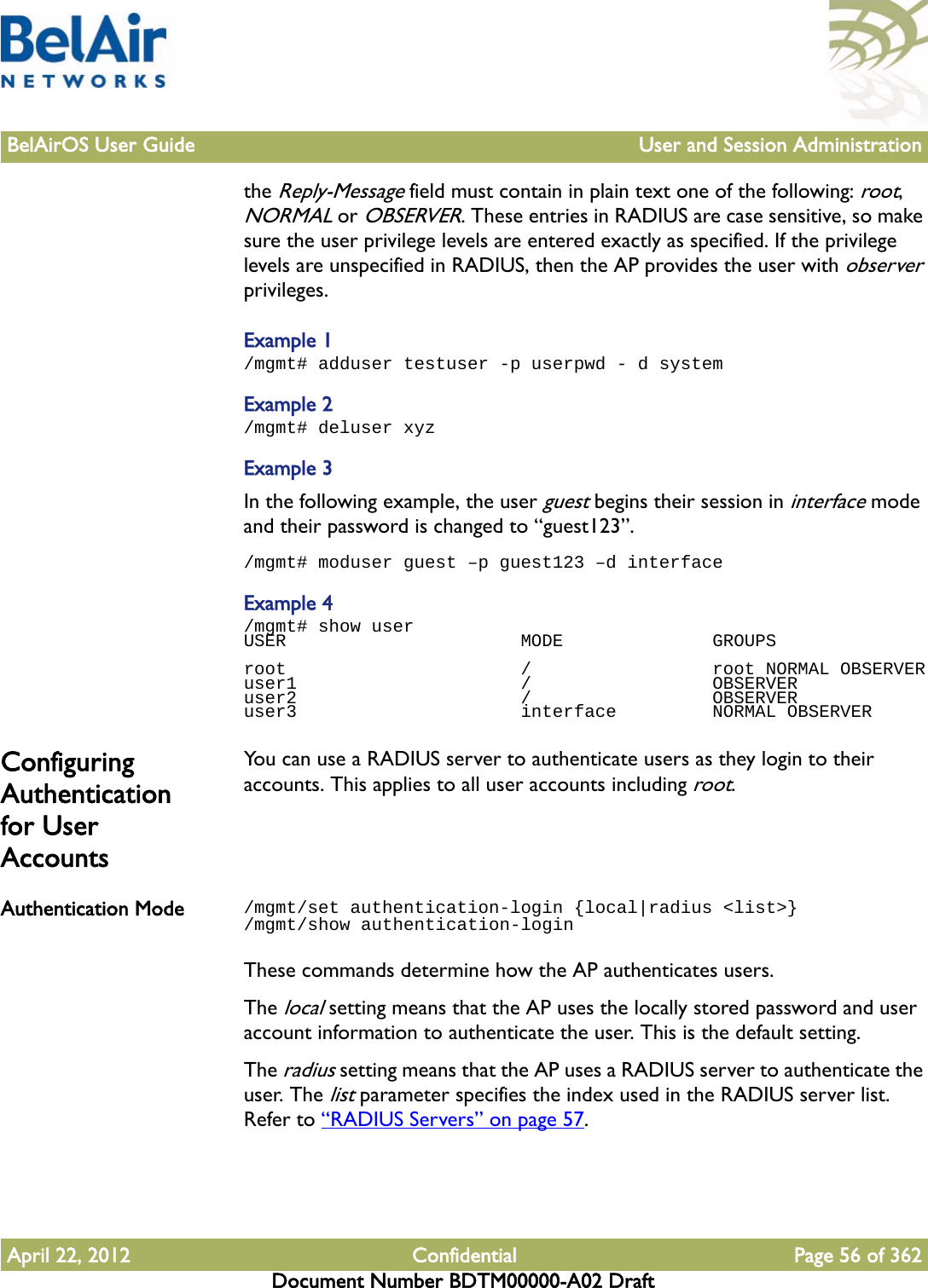
![BelAirOS User Guide User and Session AdministrationApril 22, 2012 Confidential Page 55 of 362Document Number BDTM00000-A02 DraftUser Accounts /mgmt/adduser <user-name> -p <passwd> [-d <mode>] [-g <group>]/mgmt/deluser <user-name> /mgmt/moduser <user-name> [-p <passwd>] [-d <mode>] [-g <group>]/mgmt/show userThe adduser command creates a new user account. The deluser command deletes a user account. The default login, “root”, cannot be deleted.The moduser command modifies the parameters of a user account. For this command, the group parameter does not apply to changes to the root account.The show user command lists all valid user accounts, the mode in which they start their session and their maximum privilege level. For example, under Groups, normal users display NORMAL OBSERVER while the root account displays root NORMAL OBSERVER. The mode parameter sets the command mode that a user accesses when they log in. If unspecified, it defaults to a slash (/) so the user begins their session in root mode. Users with observer privileges must start their sessions in root mode.The group parameter specifies the user account’s privilege level. It can be OBSERVER or NORMAL. If unspecified, the user account has observer privileges.To use this command, you must be in mgmt mode.Note 1: The specified password is case sensitive, must consist of alphanumeric characters, must be at least six characters long, and cannot exceed 20 characters. Changes the super-user account require that you provide the super-user password.Note 2: The specified group is case sensitive.If you use a RADIUS server to authenticate users as they login, you must specify the user’s privilege level in the RADIUS Reply-Message field. Specifically, set notify <NotifyName> type {Trap | Inform} ipaddr <IP_addr> [timeout <1-1500>] [retries <1-3>] [auth {md5 | sha} <password> [priv-DES <passwd>]]delete notify <NotifyName>set authentication-trap {enable | disable}Table 5: Super-user commands (Continued)](https://usermanual.wiki/Ericsson-Wi-Fi/40005011.User-Manual/User-Guide-1698497-Page-55.png)
![BelAirOS User Guide User and Session AdministrationApril 22, 2012 Confidential Page 57 of 362Document Number BDTM00000-A02 DraftExample 1/mgmt# set authentication-login radius 1,2Example 2mgmt# show authentication-loginAuthentication Login is radiusRadius Authentication server table------------------------------------- Index : 1 Radius Server Address : 10.1.3.254 UDP port number : 1812 Radius Client Address : 10.1.3.48 Timeout : 3-------------------------------------------- Index : 2 Radius Server Address : 10.1.3.253 UDP port number : 1812 Radius Client Address : 10.1.3.48 Timeout : 3--------------------------------------------RADIUS Servers /protocol/radius/set server <server-idx> <IP_addr> <shared-secret> [authport <server-port>] [acctport <acct-port>] [interface {system | vlan <vlan_id>}] [timeout <seconds>] [reauthtime <seconds>]/protocol/radius/set server-state <server-idx> {enabled|disabled}/protocol/radius/del server <server-idx>/protocol/radius/show serversThese commands allow you to specify a list of RADIUS servers that you can use to authenticate users. The list can contain up to 10 servers.The IP_addr parameter specifies the IP address of the RADIUS server.The shared-secret parameter specifies the password for access to the RADIUS server.The authport parameter ranges from 0 to 65535. It specifies the UDP port number of the RADIUS server (typically 1812).The acctport parameter ranges from 0 to 65535. It specifies the UDP port number for RADIUS accounting data (typically 1813).The interface parameter specifies the interface to associate the AP RADIUS client to. This can be the AP’s system interface or any VLAN interface. The vlan_id parameter ranges from 1 to 3015 and from 3018 to 4045. The default value is system.](https://usermanual.wiki/Ericsson-Wi-Fi/40005011.User-Manual/User-Guide-1698497-Page-57.png)
![BelAirOS User Guide User and Session AdministrationApril 22, 2012 Confidential Page 58 of 362Document Number BDTM00000-A02 DraftThe timeout parameter ranges from 2 to 300. It specifies the interval (in seconds) after which the RADIUS client considers that the remote server has timed out if a reply is not received. The default value is 10 seconds.The reauthtime parameter ranges from 0 to 50000000. It specifies the RADIUS re-authentication time (in seconds). This forces the AP to check all connected clients with the RADIUS server (that is, make sure they are still allowed to access the network) at the specified interval. You only need to configure this parameter if it is not specified on the RADIUS server. Setting the interval to zero disables this feature. The maximum interval time is 2147483647. If you enter a higher number, the value is set to its maximum.Note: Make sure the user’s privilege level are correctly specified in the RADIUS Reply-Message field. Refer to “User Accounts” on page 55.Example 1/protocol/radius# set server 3 172.16.1.20 my-secret12345 authport 1812 acctport 1813 interface system timeout 15 reauthtime 1Example 2/protocol/radius# set server-state 3 enabledCLI and Web SessionsThe AP allows you to manage CLI and Web session, such as listing and terminating sessions as well as configuring the idle timeout period.Session Management /system/show sessions/system/terminate session <session_index>The show sessions command lists all active CLI and Web interface sessions. The current session is flagged with an asterisk besides its session index number.The terminate session command allows you to terminate any CLI or Web session.Example/system# show sessionsindex user type IP address since last-cmd timeout tssh logging----- -------- ------- --------------- --------- --------- --------- --------- --------- 1 root telnet 10.9.9.14 0:27:57 0:01:43 0:30:00 inactive active 9 root telnet 10.9.9.14 0:22:09 0:00:00 0:30:00 inactive active11[*] root web 10.9.9.14 0:13:51 0:13:51 1:00:00 In this example, the current session is session 11 with an idle period set at 1hour.](https://usermanual.wiki/Ericsson-Wi-Fi/40005011.User-Manual/User-Guide-1698497-Page-58.png)
![BelAirOS User Guide User and Session AdministrationApril 22, 2012 Confidential Page 60 of 362Document Number BDTM00000-A02 DraftExamples/system#set prompt string BelAir-128-50-46-189/system#set prompt selection string[BelAir-128-50-46-189]/system#system switch BA20E-A[BelAir-128-50-46-189]/system#set prompt selection switch-name[BA20E-A]/system#set prompt selection switch-name[BA20E-A]/system#set prompt selection default/system# show promptUser-defined string: BelAir-128-50-46-189prompt selection: default](https://usermanual.wiki/Ericsson-Wi-Fi/40005011.User-Manual/User-Guide-1698497-Page-60.png)
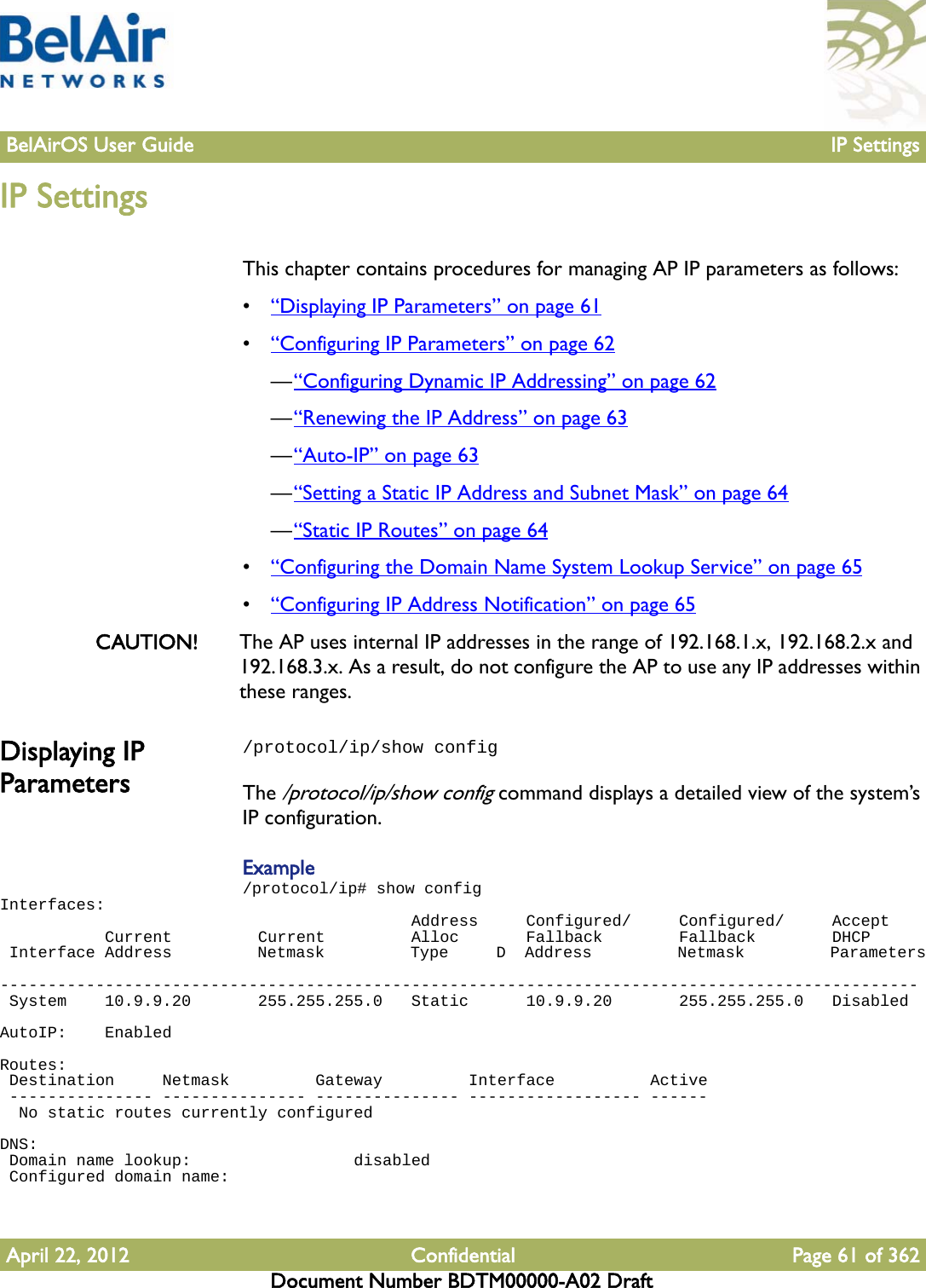
![BelAirOS User Guide IP SettingsApril 22, 2012 Confidential Page 62 of 362Document Number BDTM00000-A02 Draft Configured primary DNS server: 0.0.0.0 Configured secondary DNS server: 0.0.0.0Configuring IP ParametersYou can configure:• dynamic IP addressing• a static IP address and subnet mask, as well as static IP routes. Configuring Dynamic IP Addressing/protocol/ip/set interface {system | vlan <vlan_id>} dynamic fallback-ip <address> <mask> accept-dhcp-params {enabled|disabled} [delay-activation]/protocol/ip/del ip vlan <vlan_id>The set interface command specifies that a Dynamic Host Configuration Protocol (DHCP) server provides IP addresses for the AP. This includes IP addresses for the AP’s management interface as well as any VLANs it may have. If you specify a new VLAN, then that VLAN is created. The del ip vlan command deletes VLAN IP parameters previously created with the set interface command.The vlan_id parameter ranges from 1 to 3015 and from 3018 to 4045. If the IP address is dynamically set, BelAir Networks recommends that you also configure the switch name, location and contact parameters. These parameters then allow you to identify the AP if you later need to do a remote CLI session. Refer to “System Identification Parameters” on page 67.In addition to providing the IP address, the DHCP server can be used to supply additional parameters including:• a TFTP server and a script file name• DNS server IP address and a domain name• a SNTP server list and time offsetThe accept-dhcp-params parameter controls whether the AP accepts additional parameters from the DHCP server or not. Refer to “DHCP Options” on page 78 for details. The delay-activation parameter specifies that the new IP parameters do not take effect until after you execute a config-save command. BelAir Networks recommends that you always specify delay-activation if you change the system IP parameters. Otherwise you will need to start a new CLI session using the new IP address to execute the config-save command to save your changes.](https://usermanual.wiki/Ericsson-Wi-Fi/40005011.User-Manual/User-Guide-1698497-Page-62.png)
![BelAirOS User Guide IP SettingsApril 22, 2012 Confidential Page 64 of 362Document Number BDTM00000-A02 DraftThe auto-IP feature automatically configures the AP to have a specific default IP address based on the AP’s MAC address if it cannot get an IP address from the DHCP server or when it is in factory default mode. When auto-IP is enabled, the default IP address is 169.254.1.x with a mask of 255.255.0.0; where x is the last byte of the AP’s MAC address. When you can connect a laptop directly to the AP, the laptop also auto-configures itself with an IP address 169.254.x.x and a mask of 255.255.0.0 if it is in DHCP mode. You can then use the laptop to start a CLI session into the AP with its 169.254.1.x address.The default setting is enabled.Setting a Static IP Address and Subnet Mask/protocol/ip/set interface {system | vlan <vlan_id>} static <ip addr> <mask> [delay-activation]/protocol/ip/del ip vlan <vlan_id>The set interface command specifies that the AP uses static IP addressing for the AP’s management interface as well as any VLANs it may have. If you specify a new VLAN, then that VLAN is created. The vlan_id parameter ranges from 1 to 3015 and from 3018 to 4045. The del ip vlan command deletes VLAN IP parameters previously created with the set interface command.The delay-activation parameter specifies that the new IP parameters do not take effect until after you execute do a config-save command. BelAir Networks recommends that you always specify delay-activation if you change the system IP parameters. Otherwise you will need to start a new CLI session using the new IP address to execute the config-save command to save your changes.Example/protocol/ip# set interface system static 92.121.68.34 255.255.255.255 delay-activationThe previous command changes the system interface to have a static IP address of 92.121.68.34 and an IP mask of 255.255.255.255. The changes do not take effect until you use the config-save command to save your changes.Static IP Routes /protocol/ip/add route <dest ip addr> <dest mask> gw <gateway>/protocol/ip/del route <dest ip addr> <dest mask> gw <gateway>The ip route add command adds extra static IP routes. If your APs needs to communicate with an IP interface from another sub-network, you must add the appropriate routes to the remote IP interface. Contact your administrator to obtain the IP address and mask of the remote IP interface.](https://usermanual.wiki/Ericsson-Wi-Fi/40005011.User-Manual/User-Guide-1698497-Page-64.png)
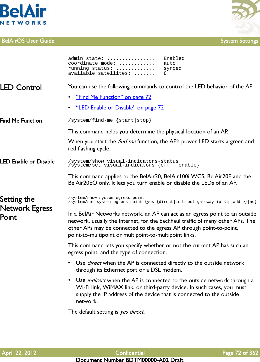
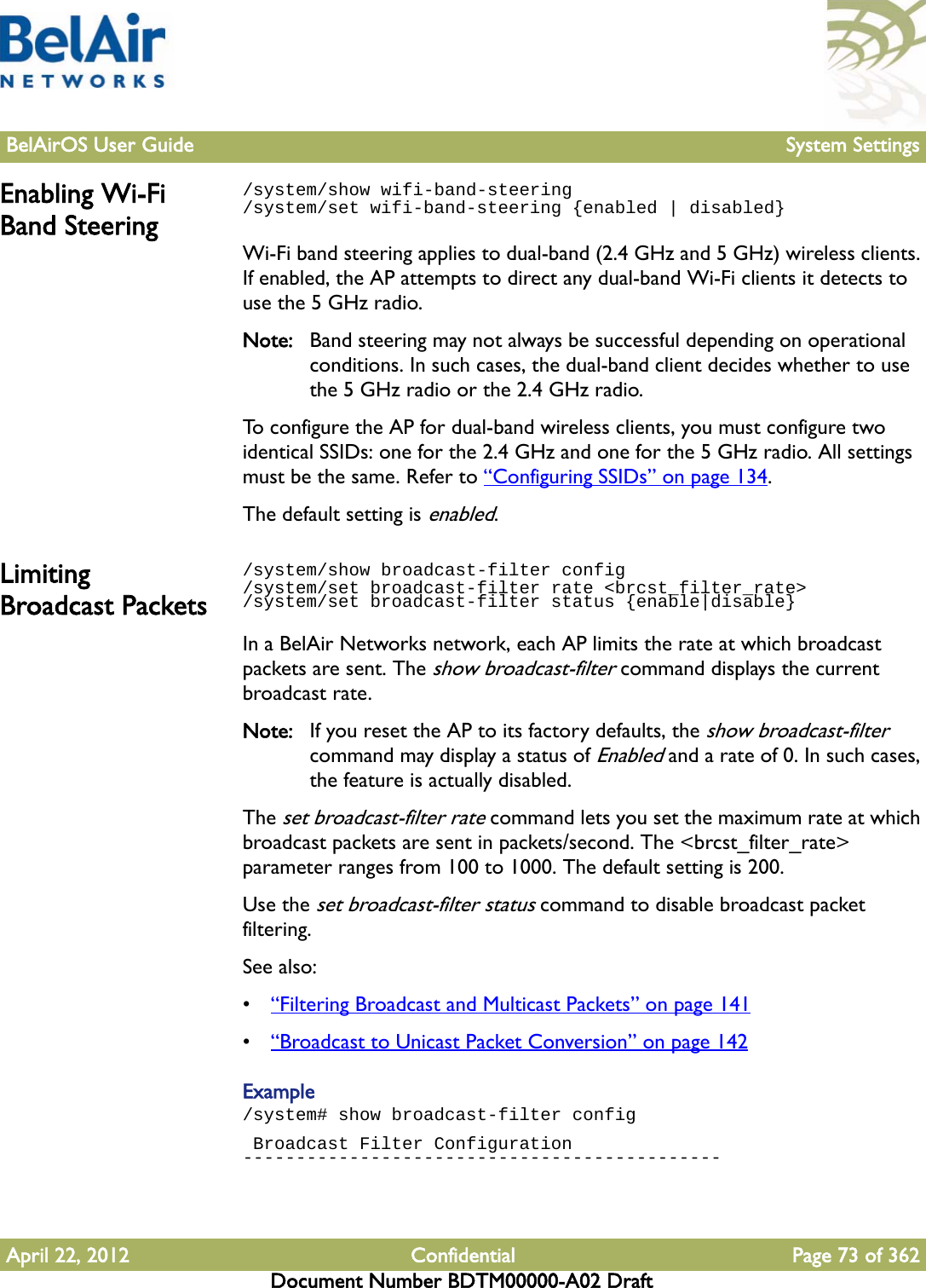
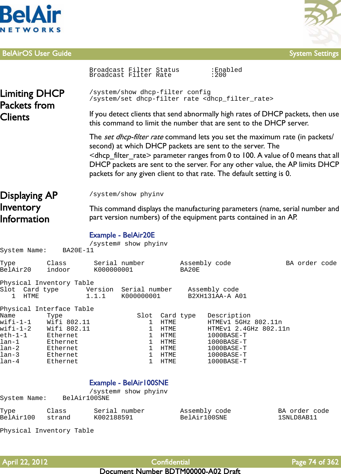
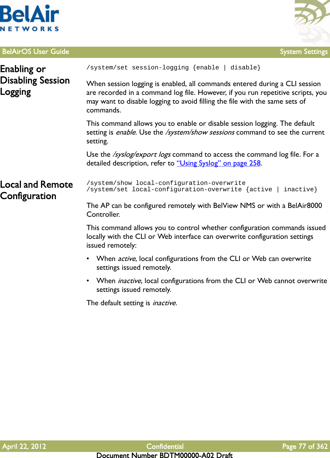
![BelAirOS User Guide System SettingsApril 22, 2012 Confidential Page 66 of 362Document Number BDTM00000-A02 DraftSystem SettingsThis chapter contains procedures for managing AP parameters as follows:•“Country of Operation” on page 66•“System Identification Parameters” on page 67•“Custom Fields” on page 67•“Configuring the System Date and Time” on page 68•“GPS Coordinates” on page 70•“LED Control” on page 72•“Setting the Network Egress Point” on page 72•“Enabling Wi-Fi Band Steering” on page 73•“Limiting Broadcast Packets” on page 73•“Limiting DHCP Packets from Clients” on page 74•“Displaying AP Inventory Information” on page 74•“Defining a Maintenance Window” on page 75•“Temperature Display” on page 75•“Displaying System Up Time” on page 76•“Displaying the Running Configuration” on page 76•“Restarting the AP” on page 76•“Creating and Using Script Files” on page 76•“Enabling or Disabling Session Logging” on page 77•“Local and Remote Configuration” on page 77Country of Operation/system/show country [detail]/system/set country <country_code>Note: These commands apply only to BelAir Networks APs purchased outside of the United States of America and its territories. For APs purchased in the United States of America and its territories, the AP’s country code is US and cannot be changed.](https://usermanual.wiki/Ericsson-Wi-Fi/40005011.User-Manual/User-Guide-1698497-Page-66.png)
![BelAirOS User Guide System SettingsApril 22, 2012 Confidential Page 67 of 362Document Number BDTM00000-A02 DraftThese commands allow you to adjust the radios in your AP to conform to the regulatory requirements for your country. This includes valid radio channel ranges as well as transmit power levels and the use of Dynamic Frequency Selection (DFS), a regulatory requirement in some jurisdictions. The show country command displays the current country of operation. Specifying the detail parameter also displays both the name and the ISO 3066 identity code for all supported countries. The set country sets the country of operation for your AP. The <country_code> parameter is the ISO 3066 identifier for the country as listed by the show country detail. The default value is US. CAUTION! Improper setting of an AP’s country setting may exceed regulatory requirements and void the operator’s right to operate the radio equipment. Contact BelAir Networks for details regarding country specific approvals. Additional country settings are also available by contacting BelAir Networks.System Identification Parameters/system/set system-id ([switch <name>] [contact <firm>] [location <place>])/system/show system-idThese commands let you manage system identification parameters such as switch name, switch contact information and physical switch location. The <name> parameter is limited to 32 characters.ExampleThe following example sets the switch name to BA20E the contact information to BelAirNetworks and its location to PoleNumber1./system# system-id switch BA20E contact BelAirNetworks location PoleNumber1Custom Fields /system/set custom ([field1 <random_str>][field2 <random_str>] [field3 <random_str>][field4 <random_str>] [field5 <random_str>])/system/show custom fieldsThese commands let you manage the contents of up to five data fields that you can use to store any information of your choosing. Each field can store up to 50 characters except for custom field 1 which is limited to 32 characters. Custom field data is saved with the AP’s configuration data.Example/system# show custom fieldsCustom Field 1: Mesh main node](https://usermanual.wiki/Ericsson-Wi-Fi/40005011.User-Manual/User-Guide-1698497-Page-67.png)
![BelAirOS User Guide System SettingsApril 22, 2012 Confidential Page 68 of 362Document Number BDTM00000-A02 DraftCustom Field 2: Used for experimentsCustom Field 3: Zone 3 masterCustom Field 4: Services customer xyzCustom Field 5: First in serviceConfiguring the System Date and TimeThe system date and time can be configured:• manually•using a Simple Network Time Protocol (SNTP) serverIn both cases, you can use an offset to convert the displayed Coordinated Universal Time (UTC) to local time.The IP addresses of the SNTP servers and the time offset can also be specified automatically through DHCP. See “DHCP Options” on page 78.Manual Date and Time Configuration/system/set date <YYYY-MM-DD> [time <hh:mm:ss>]/system/set time <hh:mm:ss>/system/set time offset <hour_offset:minute_offset>/system/show date/system/show timeoffsetThe set date and set time commands set the current date and time. The value must be formatted as follows:• YYYY is the year• MM is the month• DD is the date• hh specifies the hour• mm specifies the minutes• ss specifies the secondsYou must enter the exact date and time format as specified; that is, four digits for the year and two digits for the month, day, hour, minutes and seconds.The set time offset command configures an offset that is used to convert the displayed UTC time to local time. The hour_offset portion of the parameter ranges from -12 to +13. The minute_offset portion of the parameter ranges from 0 to 59.](https://usermanual.wiki/Ericsson-Wi-Fi/40005011.User-Manual/User-Guide-1698497-Page-68.png)
![BelAirOS User Guide System SettingsApril 22, 2012 Confidential Page 70 of 362Document Number BDTM00000-A02 DraftExample 1/protocol/sntp# set ip-address primary 10.1.1.2Example 2/protocol/sntp# set timeoffset -4 30Example 3/protocol/sntp# show statusSNTP process is runningEffective SNTP Timeoffset:===========================SNTP Timeoffset origin: SNTP schemaSNTP Time Offset: 6:00Effective SNTP server:======================SNTP Servers origin: SNTP schemaActive Server: Primary - 0.pool.ntp.orgSNTP server Primary : 0.pool.ntp.orgSNTP server Secondary : 1.pool.ntp.orgDHCP timeserver Primary : 0.0.0.0DHCP timeserver Secondary: 0.0.0.0GPS Coordinates For the BelAir20, BelAir100i, BelAir20E, BelAir20EO, BelAir100N, BelAirSN and the BelAir2100:/system/set coordinates [latitude <-90,+90> ] [longitude <-180,+180>]/system/show coordinatesFor the BelAir100SNE:/system/set coordinates {auto|{manual {copygps|[[latitude <-90,+90>] [longitude <-180,+180>]]}}}/system/set gps admin-state [enable|disable]/system/show gps status/system/show coordinatesThese commands allow you to specify the exact geographic location of an AP. You can then use the Global Positioning System (GPS) coordinates to locate an AP in the field.The BelAir100SNE has additional GPS commands as follows:• The set coordinates auto command lets you use the AP’s built-in antenna and GPS satellites to automatically determine the AP’s location. To use this functionality, you must first enable the GPS admin state.• The set gps admin-state command allows you to control the use of the automatic GPS coordinate detection system. To disable the admin state, the](https://usermanual.wiki/Ericsson-Wi-Fi/40005011.User-Manual/User-Guide-1698497-Page-70.png)
![BelAirOS User Guide System SettingsApril 22, 2012 Confidential Page 75 of 362Document Number BDTM00000-A02 DraftSlot Card type Version Serial number Assembly code 1 DRUE 1.1.1 K002188591 B2XH105AA-A A01 9 CM 3.0.0 BRG35503BelPhysical Interface TableName Type Slot Card type Descriptionwifi-1-1 Wifi 802.11 1 DRUE DRUEv1 2.4GHz 802.11nwifi-1-2 Wifi 802.11 1 DRUE DRUEv1 5GHz 802.11neth-1-1 Ethernet 1 DRUE 1x1000baseTx [Electrical: Single]cm-9-1 DOCSIS cable-modem 9 CM Cable ModemDefining a Maintenance Window/system/set maintenance-window {{enabled {hh:mm hh:mm} | disabled }}/system/show maintenance-windowUse these commands to define and enable a maintenance window where generated alarms do not count against the alarm threshold. For details, see “Setting the Tunnel Down Alarm Threshold” on page 223. For the BelAir100SN and the BelAir100SNE, see also “Setting the Cable Modem Interface Down Alarm Threshold” on page 98.By default, the maintenance window is enabled and runs from midnight (00:00) to 7 am (07:00). Specified window start and end times are rounded down to the nearest 15-minute increment. Example/system# set maintenance-window enabled 00:14 03:20The previous command sets the maintenance window to run from midnight (00:00) to 3:15 am. Temperature Display/system/show environmentThe show environment command applies to the BelAir100N, BelAir100SN, BelAir100SNE, and the BelAir2100. It displays the AP’s the internal temperature (in degrees Celsius).Example/system# show environment Temperature Ambient: 36.5 Celsius Power supply Source: Unable to determine main power status Battery State: BelAir100SN does not support battery monitor.](https://usermanual.wiki/Ericsson-Wi-Fi/40005011.User-Manual/User-Guide-1698497-Page-75.png)
![BelAirOS User Guide System SettingsApril 22, 2012 Confidential Page 76 of 362Document Number BDTM00000-A02 DraftDisplaying System Up Time/system/show sysuptimeThis command displays the time the system has been operating.Example/system# show sysuptimeSystem Up Time: 234 days, 16:45:32.34Displaying the Running Configuration/system/show running-configuration This command displays the configuration that the AP is currently operating with. It executes a series of show commands with results displayed on the CLI screen. Use the scroll bar of the Telnet or SSH window to see any particular section of the output. Restarting the AP /system/reboot [{force}]/system/show restart-reasonThe reboot command restarts the entire AP. You must confirm your intent before the AP is rebooted.Under some circumstances, a reboot may be prevented because of processing from other user sessions. Use the force parameter to override these restrictions and restart the AP regardless.The show restart-reason command displays the reason for the last restart.See also “Restarting a Card” on page 88.Example/system# show restart-reason Previous reboot was a cold restart initiated by user.Creating and Using Script FilesYou can use script files to:• make repetitive tasks quicker and easier to do• automate the configuration of an AP when it starts up. See “AP Auto-configuration” on page 78.To help create your scripts, follow the guidelines in “Scripting Guidelines” on page 309.](https://usermanual.wiki/Ericsson-Wi-Fi/40005011.User-Manual/User-Guide-1698497-Page-76.png)
![BelAirOS User Guide AP Auto-configurationApril 22, 2012 Confidential Page 80 of 362Document Number BDTM00000-A02 DraftPre-requisites To use DHCP options, your DCHP server must be configured to supply the information requested by the AP. In particular, make sure of the following:• Your DHCP server supplies a list of SNTP servers instead of NTP servers and that they are listed in order of preference.• Your DHCP server assigns only one default route, even you are using many different IP interfaces on the same AP (for example, a management IP interface and a VLAN IP interface). Configuring and Using DHCP Options To use DHCP options, you must: 1 Set the default IP address assignment of an interface to dynamic and set the accept-dhcp-params parameter to enabled. See “Configuring Dynamic IP Addressing” on page 62.2 Specify which specific parameters to accept from DHCP server. See “Accepting Specific DHCP Parameters” on page 80.The AP then contacts the DHCP server to request the parameters.Accepting Specific DHCP Parameters/protocol/ip/set dhcp-accept ([dns-domain {enabled|disabled}] [dns-server {enabled|disabled}] [tftp-download {enabled|disabled}] [time-server {enabled|disabled}] [time-offset {enabled|disabled}])These commands control whether the individual parameters supplied by the DHCP server are accepted or not by the AP. To use this command you must first set the default IP address assignment for the interface to dynamic and set the accept-dhcp-params parameter to enabled. See “Configuring Dynamic IP Addressing” on page 62.By default, the AP accepts all parameters from the DHCP server; that is, each of these parameters is set to enabled.The dns-domain parameter controls the domain name option used to perform DNS requests. Only one domain name is valid at any one time per AP. See “Configuring the Domain Name System Lookup Service” on page 65. The dns-server parameter controls DNS server IP addresses. Up to two DNS servers are supported. See “Configuring the Domain Name System Lookup Service” on page 65.The tftp-download parameter controls two DHCP options: TFTP server IP address and script file. Enabling this option causes a TFTP session to be created and the script file to be downloaded and executed during startup.](https://usermanual.wiki/Ericsson-Wi-Fi/40005011.User-Manual/User-Guide-1698497-Page-80.png)
![BelAirOS User Guide AP Auto-configurationApril 22, 2012 Confidential Page 82 of 362Document Number BDTM00000-A02 Draftserver is bn_00_0d_67_0c_21_76. The username must be in lower case and must exist in the FTP server.—The FTP password used is the md5sum of the username. To obtain this, do echo <username> | md5sum. Omit the spaces and dash at the end of the md5sum output. 3 In the FTP home directory for the user, the AP looks for a script file named bn_config.cfg. Configuration Download ProfileWith the configuration download profile you specify:• the filename of the script file• the server from which to get the script file• a user-name and passwordYou can specify the server by either its IP address or its name. If both are specified, the IP address has precedence. The default name is belairconfig.com.The script file is downloaded and executed only during a startup. If the script on the server changes, it is not sent to the AP until the next time the AP reboots or starts up. Pre-requisites To use a configuration download profile, your server must be configured with the appropriate user accounts and passwords. The account must contain a valid script file.Also, if you identify the server with a name, you need a DNS server to resolve names to IP addresses. Using a Configuration Download Profile/system/set config-download [server <name_or_ip_addr>] [auto-conf-protocol {ftps|ftp|tftp] [filename <filename>] [user <user_name>] [password <pword>] {enabled|disabled}/system/show config-download statusThese commands provision the configuration download profile.The server may be identified by supplying either its IP address or providing its name. The default server name is belairconfig.com. The default protocol is FTPS. The default user name and password is anonymous. The default filename is auto-config.txt. By default, the configuration download file is disabled.](https://usermanual.wiki/Ericsson-Wi-Fi/40005011.User-Manual/User-Guide-1698497-Page-82.png)
![BelAirOS User Guide Card SettingsApril 22, 2012 Confidential Page 86 of 362Document Number BDTM00000-A02 Draft /wifi-2-1 (DRUEv1 5GHz 802.11n) /eth-1-1 (1x1000baseTx [Electrical: Single]) /mgmt /protocol /ip /radius /rstp /snmp /sntp /te-syst (tunnel) /qos /services /auto-conn /mobility /ssh /ssl /syslog /system /diagnosticsExample 3 - BelAir20E/card# mode /htme-1Example 4 - BelAir100SNE/card# mode /drue-1Displaying Card InformationThe following sections describe commands that display card parameters.Displaying the Card Physical Data/card/<card_type>-<n>/show infoThis command applies to all cards types except bts. This command displays various physical aspects of the card.Example 1 - BelAir20E/card/htme-1# show infoSlot Type Version Serial Number Assembly Code==== ==== ======= =============== ===============1 htme 1 844000010 B2CH103AA-A A01Example 2 - BelAir100SNE/card/drue-1# show infoSlot Type Version Serial Number Assembly Code==== ==== ======= =============== ===============1 drue 1 K002188591 B2XH105AA-A A01](https://usermanual.wiki/Ericsson-Wi-Fi/40005011.User-Manual/User-Guide-1698497-Page-86.png)
![BelAirOS User Guide Card SettingsApril 22, 2012 Confidential Page 88 of 362Document Number BDTM00000-A02 DraftLowTotal: 125068 kBLowFree: 54996 kBSwapTotal: 0 kBSwapFree: 0 kBDirty: 0 kBWriteback: 0 kBAnonPages: 9196 kBMapped: 9876 kBShmem: 2688 kBNote: The type and amount of card memory usage data may vary depending on the card‘s software version.Card Administrative StateFor the BelAir20 and BelAir100i WCS:/card/<card_type>-<n>/show stateFor the BelAir20E, BelAir20EO, BelAir100N, BelAir100SN, BelAir100SNE and BelAir2100:/card/<card_type>-<n>/show state/card/<card_type>-<n>/set state {enabled | disabled}These commands apply to all cards types except bts. These commands manage the card’s administrative state. Example - BelAir20E/card/htme-1# show stateAdmin:Up Status:runningRestarting a Card /card/<card_type>-<n>/reboot [{force}]This command applies to the BelAir20E, BelAir20EO, BelAir100N, BelAir100SN, and BelAir100SNE. It restarts a specific card. You must confirm your intent before the card is rebooted.Under some circumstances, a reboot may be prevented because of processing from other user sessions. Use the force parameter to override these restrictions and restart the card regardless.Card CPU and Memory Performance Monitoring Statistics/card/<card_type>-<n>/show pm {fifteen-min|day}[{{<0-96>|<0-7>}|all]This command displays a card’s CPU and memory performance measurements either for a specific time interval or for a series of time intervals. The valid parameter options are:•fifteen-min, fifteen-min 0 to fifteen-min 96•day, day 0 to day 7](https://usermanual.wiki/Ericsson-Wi-Fi/40005011.User-Manual/User-Guide-1698497-Page-88.png)
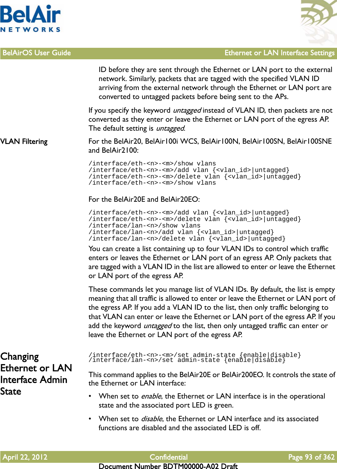
![BelAirOS User Guide Ethernet or LAN Interface SettingsApril 22, 2012 Confidential Page 92 of 362Document Number BDTM00000-A02 DraftExample/interface/eth-1-1# show statusType : 1x1000baseTx [Electrical: Single]Admin Status : EnabledLink State : UpSpeed : 100 MbpsMode : Full DuplexAuto-Negotiation : EnabledMac Address : 00:0D:67:0C:23:38Managing Egress AP TrafficIn a BelAir Networks network, the Ethernet or LAN port of an AP can act as an egress point for the backhaul traffic of many other APs. The other APs may be connected to the egress AP through point-to-point, point-to-multipoint or multipoint-to-multipoint links.VLAN Conversion For the BelAir20, BelAir100i WCS, BelAir100N, BelAir100SN, BelAir100SNE and BelAir2100:/interface/eth-<n>-<m>/show pvid/interface/eth-<n>-<m>/set pvid {<vlan_id>|untagged}/interface/eth-<n>-<m>/set reverse-pvid {<vlan_id>|untagged}For the BelAir20E and BelAir20EO:/interface/eth-<n>-<m>/show pvid/interface/eth-<n>-<m>/set pvid {<vlan_id>|untagged}/interface/eth-<n>-<m>/set reverse-pvid {<vlan_id>|untagged}/interface/lan-<n>/show pvid/interface/lan-<n>/set pvid {<vlan_id>|untagged}/interface/lan-<n>/set reverse-pvid {<vlan_id>|untagged}These commands let you convert the VLAN tagging of traffic entering or leaving the Ethernet or LAN port of an egress AP:• The set pvid command applies when traffic between APs uses VLAN IDs and these VLAN IDs must be removed before the traffic leaves the AP through the Ethernet or LAN port to the external network. If you use the set pvid command and specify a VLAN ID, untagged VLAN packets coming from external network through the Ethernet or LAN port are converted to tagged packets with the specified VLAN ID before they are sent to the APs. Similarly, packets that are tagged with the specified VLAN ID are sent to the external network through Ethernet or LAN port as untagged VLAN packets.• The set reverse-pvid command applies when traffic between APs is untagged and must be tagged with a VLAN ID before it leaves the AP through the Ethernet or LAN port to the external network. If you use the set reverse-pvid command and specify a VLAN ID, untagged VLAN packets coming from APs are converted to tagged packets with the specified VLAN](https://usermanual.wiki/Ericsson-Wi-Fi/40005011.User-Manual/User-Guide-1698497-Page-92.png)
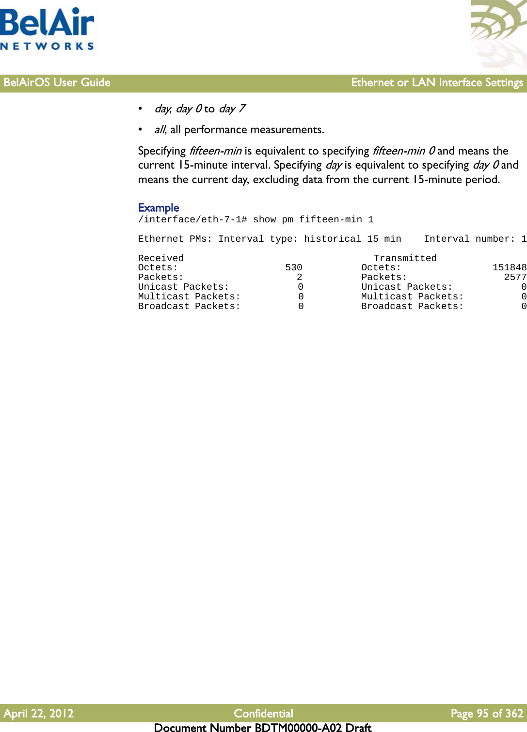
![BelAirOS User Guide Ethernet or LAN Interface SettingsApril 22, 2012 Confidential Page 94 of 362Document Number BDTM00000-A02 DraftThe default is enabled.Use the corresponding show status command to view the current admin state of the Ethernet or LAN interface.Ethernet or LAN Port StatisticsFor the BelAir20, BelA100i WCS, BelAir100N, BelAir100SN, BelAir100SNE and BelAir2100:/interface/eth-<n>-<m>/show statisticsFor the BelAir20E and BelAir20EO:/interface/eth-<n>-<m>/show statistics/interface/lan-<n>/show statisticsThis command displays various statistics about the traffic on the AP‘s Ethernet or LAN port.Example/interface/eth-1-1# show statisticsStatistics: Rx Packets : 13196 Bytes : 866242 Dropped : 0 Errors : 0 Tx Packets : 1298 Bytes : 97713 Dropped : 0 Errors : 0Ethernet or LAN Port Performance Monitoring StatisticsFor the BelAir20, BelA100i WCS, BelAir100N, BelAir100SN, BelAir100SNE and BelAir2100:/interface/eth-<n>-<m>/show pm {fifteen-min|day}[{<0-96>|<0-7>}|all]For the BelAir20E and BelAir20EO:/interface/eth-<n>-<m>/show pm {fifteen-min|day}[{<0-96>|<0-7>}|all]/interface/lan-<n>/show pm {fifteen-min|day}[{<0-96>|<0-7>}|all]This command displays an Ethernet or LAN port’s performance measurements either for a specific time interval or for a series of time intervals. The valid parameter options are:•fifteen-min, fifteen-min 0 to fifteen-min 96](https://usermanual.wiki/Ericsson-Wi-Fi/40005011.User-Manual/User-Guide-1698497-Page-94.png)
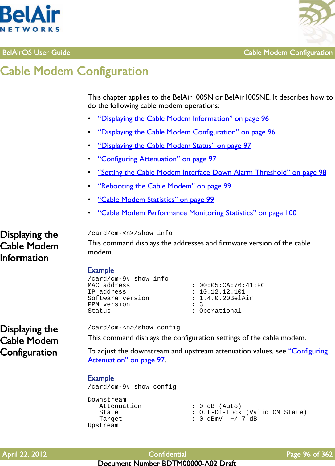
![BelAirOS User Guide Cable Modem ConfigurationApril 22, 2012 Confidential Page 97 of 362Document Number BDTM00000-A02 Draft Attenuation : 2 dB (Manual) State : Manual Target : 25 dBmV +/-1 dBDisplaying the Cable Modem Status/card/cm-<n>/show statusThis command displays the operational parameters of the cable modem. For proper operation, the status must be as follows:• the QAM lock, FEC sync, and MPEG sync fields must be yes. • the weak signal field must be no.• the downstream power and the upstream power must be in the range specified in the DOCSIS 3.0 specification.• the signal-to-noise ratio (SNR) must be 23.5 or higher when the QAM mode is 64 and must be 30.0 or higher when the QAM mode is 256.To adjust the downstream and upstream power values, see “Configuring Attenuation” on page 97.Example/card/cm-9# show statusModem status : OperationalChannel 1 2 3 4 Downstream freq (MHz) : 699 645 657 663 Timing offset (PPM) : 0 0 0 0 Carrier offset (Hz) : -16548 -13034 -15819 -14321 QAM mode : 256 256 256 256 QAM lock : yes yes yes yes FEC Sync : yes yes yes yes MPEG Sync : yes yes yes yes Weak signal : no no no no Upstream power (dBmV) : 57.0 -1.0 -1.0 -1.0 Downstream power (dBmV) : -17.7 -19.0 -19.1 -19.2 Downstream SNR (dB) : 29.1 28.4 28.5 28.7Configuring Attenuation/card/cm-<n>/set attenuation {upstream|downstream} { mode {auto|manual [<att_val>]} | parameters target <target_val> delta <delta_val> }This command lets you set the upstream or downstream attenuation applied to the cable modem’s RF signal path. You can use manual or automatic attenuation settings. For manual settings, specify the <att_val> parameter, which ranges from 0 to 20 in 1 dB steps. The default value setting is 0 dB.](https://usermanual.wiki/Ericsson-Wi-Fi/40005011.User-Manual/User-Guide-1698497-Page-97.png)
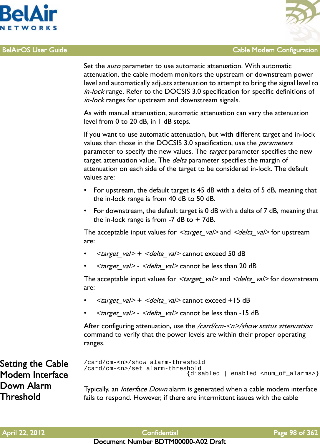
![BelAirOS User Guide Cable Modem ConfigurationApril 22, 2012 Confidential Page 99 of 362Document Number BDTM00000-A02 Draftmodem interface, it may take time to identify and correct the root cause. During this period, multiple Interface Down alarms would be generated.Enabling the alarm threshold reduces the number of Interface Down alarms generated per calendar day. If the threshold is reached, the system generates instead a single Excess Cable Modem Interface Down Events alarm and stops generating additional Interface Down alarms. The Interface Down events are still tracked through the tunnel’s performance monitoring statistics, allowing you to analyze the behavior.The <num_of_alarms> parameter ranges from 2 to 50. By default, the alarm threshold is enabled with a setting of 5, meaning that the Excess Cable Modem Interface Down Events alarm is generated once 5 Interface Down events occur in a day. Alarms generated during a maintenance window do not count against the alarm threshold. For details see, “Defining a Maintenance Window” on page 75.Rebooting the Cable Modem/card/cm-<n>/reboot [set-default]Use this command to reboot the cable modem. Use the set-default parameter to return the cable modem settings to factory defaults.Cable Modem Statistics/card/cm-<n>/show statistics {all|up_channel|signal_quality|uptime|status}This command applies to the BelAir100SN and the BelAir100SNE. It displays additional data that can be retrieved from the cable modem:•all, all data•up_channel, display up channel data•signal_quality, display signal quality data•uptime, display cable modem up time•status, display cable modem status dataExample/card/cm-9#show statistics allSignal quality Unerroreds : 2140459029 2140178006 2140177890 2140176599 Correcteds : 356 156 195 447 Uncorrectables : 4917 2309 2393 3421 Signal Noise : 350 354 352 349 Microreflections : 41 41 42 39Status TxPower : 505 0 0 0](https://usermanual.wiki/Ericsson-Wi-Fi/40005011.User-Manual/User-Guide-1698497-Page-99.png)
![BelAirOS User Guide Cable Modem ConfigurationApril 22, 2012 Confidential Page 100 of 362Document Number BDTM00000-A02 Draft Resets : 3 LostSyncs : 1 InvalidMaps : 0 InvalidUcds : 0 InvalidRangingResps : 0 InvalidRegistrationResps: 0 T1Timeouts : 0 T2Timeouts : 0 UsT3Timeouts : 0 0 0 0 UsT4Timeouts : 0 0 0 0 RangingAborteds : 0 0 0 0 DocsisOperMode : 3Up Channel Frequency : 28000000 0 0 0 Width : 28000000 0 0 0 TxTimingOffset : 1243 0 0 0Up time 9days20h:27m:37sCable Modem Performance Monitoring Statistics/card/cm-<n>/show pm {fifteen-min|day}[{{<0-96>|<0-7>}| all{availability|signal_quality <channel>|resets|ranging <channel>}]This command This command applies to the BelAir100SN and the BelAir100SNE. It displays a cable modem’s performance measurements either for a specific time interval or for a series of time intervals. The valid parameter options are:•fifteen-min, fifteen-min 0 to fifteen-min 96•day, day 0 to day 7Specifying fifteen-min is equivalent to specifying fifteen-min 0 and means the current 15-minute interval. Specifying day is equivalent to specifying day 0 and means the current day, excluding data from the current 15-minute period. Specifying all displays the statistics for all periods. With all, you can select from the following types of data: availability, signal_quality <channel>, resets, or ranging <channel>.Example 1/card/cm-9#show pm fifteen-min 1Interval type : historical 15 minInterval number : 1Unavailable Seconds : 410Example 2/card/cm-9#show pm dayInterval type : current 24 hourInterval number : 0Unavailable Seconds : 56210](https://usermanual.wiki/Ericsson-Wi-Fi/40005011.User-Manual/User-Guide-1698497-Page-100.png)

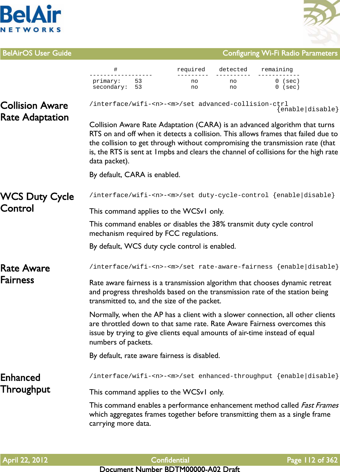
![BelAirOS User Guide Configuring Wi-Fi Radio ParametersApril 22, 2012 Confidential Page 104 of 362Document Number BDTM00000-A02 Draft•“Wi-Fi AP Security” on page 146•“Wi-Fi Backhaul Link Configuration” on page 161•“Mobile Backhaul Mesh” on page 169Displaying Wi-Fi Radio Configuration/interface/wifi-<n>-<m>/show config [{all|access|backhaul|qos|mobile}]This command displays various aspects of the radio’s configuration.Example - BelAir20E/interface/wifi-1-1# show config allSlot: 1, Card Type: htme, revision: 1, Port: 1, Radio: HTMEv1 5GHz 802.11nadmin state: ................. Enabledchannel: ..................... 149 mode: ...................... ht40plus mimo: ...................... 3x3 tx power: .................. 18.0 (dBm per-chain), 23.0 (dBm total)antenna location: ............ External Portantenna index: ............... 1antenna gain: ................ 5.0 (dBi)link distance: ............... 1 (km)base radio MAC : ............. 00:0d:67:0c:21:90Access: AP admin state: ............ Enabled secure addresses (vlan): ... none client blacklist: .......... none dhcp unicast: .............. Disabled deauth dos defense: ........ Disabled client auth trap: .......... DisabledMisc: rts-cts threshold: ......... 100 broadcast filter status: ... Disabled broadcast filter rate: ..... 200QOS: wmm: ....................... Enabled uapsd: ..................... Enabled mapping: ................... UP/DSCP voice acm: ................. Disabled video acm: ................. DisabledCommon Backhaul: privacy: ................... AES key: ....................... mesh-min-rssi............... -100 (dbm)Stationary Backhaul: link admin state: .......... Disabled link id: ................... BelAirNetworks topology: .................. meshMobile Backhaul: mobile admin state: ........ Disabled mobile link id: ............ mobile link role: .......... ss](https://usermanual.wiki/Ericsson-Wi-Fi/40005011.User-Manual/User-Guide-1698497-Page-104.png)
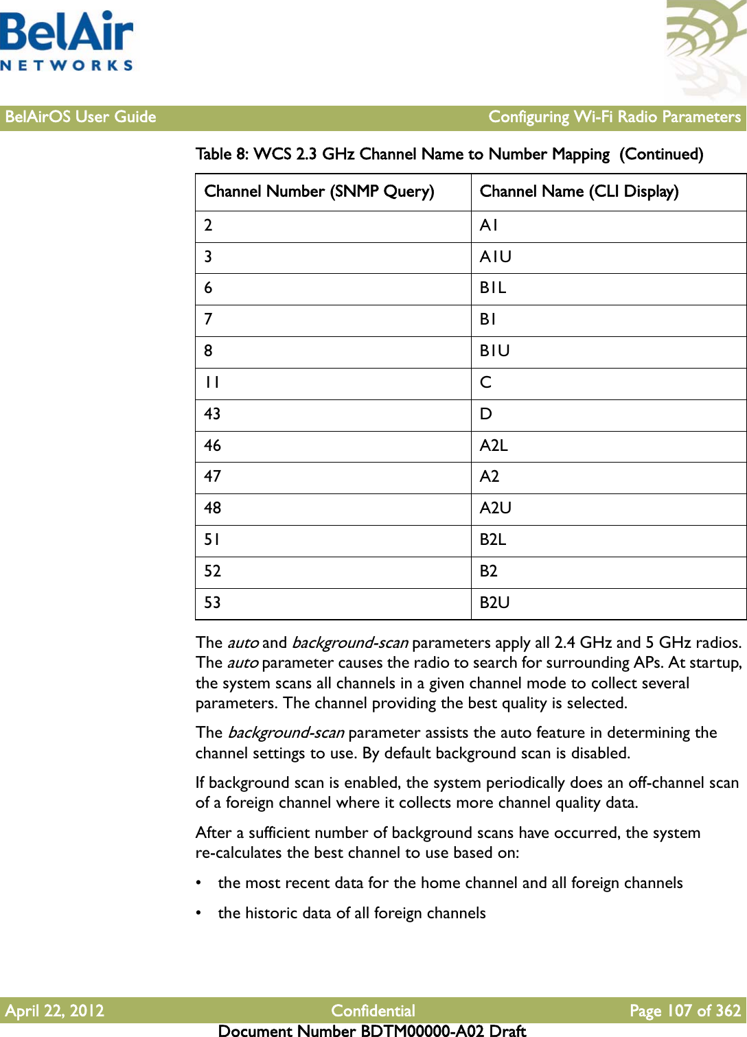
![BelAirOS User Guide Configuring Wi-Fi Radio ParametersApril 22, 2012 Confidential Page 105 of 362Document Number BDTM00000-A02 DraftBlacklist: No blacklist entriesLink Failure Detection: ...... DisabledBackhaul T1 Bandwidth limit:.. DisabledDisplaying Configuration Options/interface/wifi-<n>-<m>/show available-config-optionsThis command displays valid channel, antenna gains and transmit power values for your AP. The displayed values vary depending on the country of operation.Example - BelAir20E/interface/wifi-1-1# show available-config-optionsChannels:--------------------------------------------------------------------[Mode=ht20] 36 37 38 39 40 41 42 43 44 45 46 47 48[Mode=ht40+] 36 37 38 39 40 41 42 43 44[Mode=ht40-] 40 41 42 43 44 45 46 47 48[Mode=ht20] 149 150 151 152 153 154 155 156 157 158 159 160 161 162 163 164 165[Mode=ht40+] 149 150 151 152 153 154 155 156 157[Mode=ht40-] 153 154 155 156 157 158 159 160 161External antenna gain list:-------------------------------------------------------------------- 0.00 5.00 9.00Tx power values for channel [149] and antenna gain [5]:-------------------------------------------------------------------- 18 17 16 15 14 13 12 11 10 9Operating Channel/interface/wifi-<n>-<m>/set channel {<channel-number> [secondary <channel-number>] [channel-bandwidth {5000|2500] [channel-mode ht20|ht40plus|ht40minus|20] | auto [background-scan {enabled | disabled}]}/interface/wifi-<n>-<m>/re-scan-channelNote: The specific syntax and options for the set channel command varies depending on the type of radio being configured. Use the /interface/wifi-<n>-<m>/? command to display the options and syntax that apply to you.The set channel command lets you specify the channel settings for a Wi-Fi radio. Use the show available-config-options command to display valid channel numbers. The displayed values vary depending on the country of operation. Refer to your RF plan and site survey to determine which value you should use.](https://usermanual.wiki/Ericsson-Wi-Fi/40005011.User-Manual/User-Guide-1698497-Page-105.png)
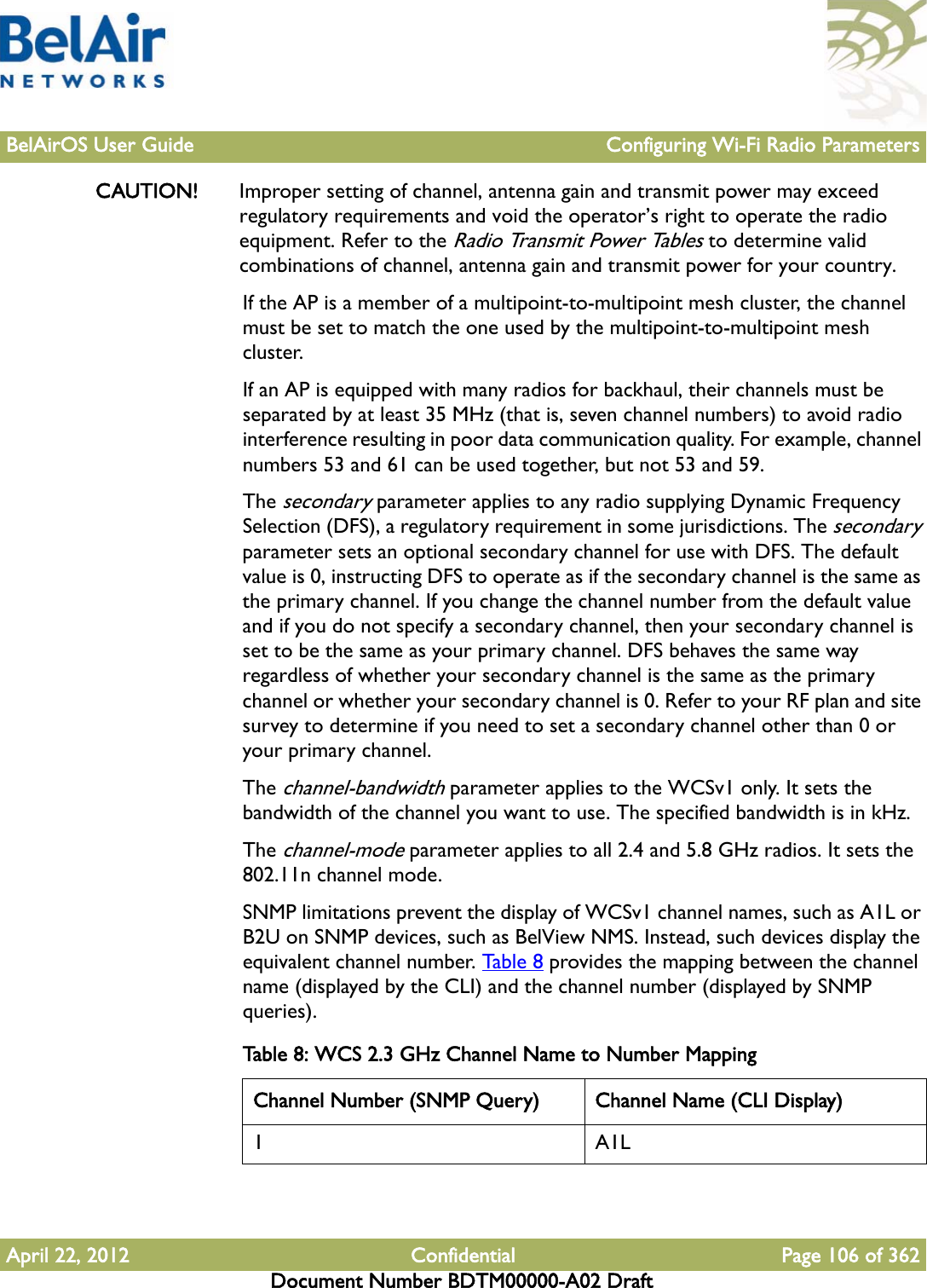
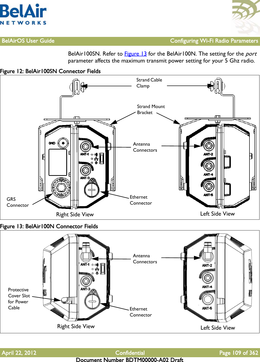
![BelAirOS User Guide Configuring Wi-Fi Radio ParametersApril 22, 2012 Confidential Page 108 of 362Document Number BDTM00000-A02 DraftIf a foreign channel is at least 20% better the home channel, then the system switches to the new channel.The re-scan-channel command causes the radio to perform another search.See also:•“Country of Operation” on page 66• the Radio Transmit Power TablesAntenna Gain For the BelAir20, BelAir100i WCS, BelAir20E, BelAir20EO and BelAir100SNE:/interface/wifi-<n>-<m>/set antenna-gain <gain>For the BelAir100N and BelAir100SN:/interface/wifi-<n>-<m>/set antenna gain <gain> [port {dedicated|shared}]For the BelAir2100:/interface/wifi-<n>-<m>/set antenna gain <gain>This command lets you specify the gain of the antenna installed with your AP. Use the show available-config-options command to display valid gain values (in dBi). The displayed values vary depending on the country of operation and the channel in use.You must set the <gain> parameter to match the gain of the antenna installed in your AP. For all countries except Korea, the default access antenna gain is 8 dBi. For Korea, the default access antenna gain is 6 dBi.CAUTION! This caution applies only to the BelAir20, BelAir100i WCS, BelAir20EO, BelAir100N, BelAir100SN and BelAir100SNE. Improper setting of channel, antenna gain and transmit power may exceed regulatory requirements and void the operator’s right to operate the radio equipment. Refer to the Radio Trans m i t Powe r Ta b les to determine valid combinations of channel, antenna gain and transmit power for your country.Use the set antenna-gain <gain> command for your AP’s 2.4 GHz DRU radio. Use the set antenna gain <gain> port {dedicated|shared} command for your AP’s 5 GHz DRU radio.Your AP’s 5 GHz DRU radio offers two sets of ports to connect antennas. If you use single-band (5 GHz) antennas, set the port parameter to dedicated and connect your antennas to port 3 and 4 of your AP. If you use dual-band (2.4 and 5 GHz) antennas, set the port parameter to shared and connect your antennas to port 1 and 2 of your AP. Refer to Figure 12 on page 109 for the](https://usermanual.wiki/Ericsson-Wi-Fi/40005011.User-Manual/User-Guide-1698497-Page-108.png)
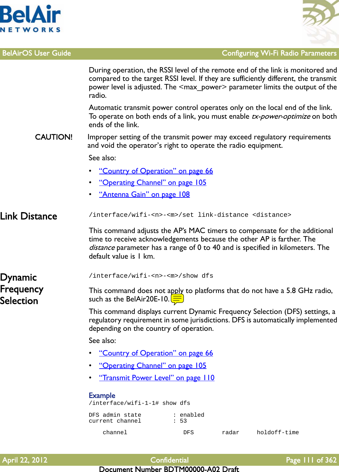
![BelAirOS User Guide Configuring Wi-Fi Radio ParametersApril 22, 2012 Confidential Page 110 of 362Document Number BDTM00000-A02 DraftSee also:•“Country of Operation” on page 66•“Operating Channel” on page 105• the Radio Transmit Power TablesTra ns m it Power Level/interface/wifi-<n>-<m>/set tx-power {<tx-power-value> [secondary <tx-power-value>]| maximum-tx-power}/interface/wifi-<n>-<m>/set tx-power {{<tx-power-value> [secondary <tx-power-value>] [tx-power-optimize {{enable [target-rssi <rssi_level>] [max-tx-power <max_power>]}|disable}]} | maximum-tx-power }This command sets the transmit power for a Wi-Fi radio. On all radios you can specify specific power values with <tx-power-value> or select maximum-tx-power which tells the radio to operate at the maximum transmit power allowed for your configuration.The range of <tx-power-value> is limited to be valid for your country of operation, physical channel in use, and type of antenna that is installed. Use the show available-config-options command to display valid transmit power values (in dBm). The displayed values vary depending on the country of operation and channel in use. If you enter a value for <tx-power-value> outside its valid range, the AP issues a warning and instead uses an appropriate minimum or maximum power setting for the radio. The default setting is to have the radio transmit at maximum power.The secondary parameter applies only to 5.8 GHz radios. It sets the transmit power for an optional secondary channel for use with Dynamic Frequency Selection (DFS), a regulatory requirement in some jurisdictions. The default is to have the same transmit power level for both the primary and secondary channel. Refer to your RF plan and site survey to determine if you need to set a different power level for the DFS secondary channel.For BelAir20EO APs equipped with a 2.4 GHz and a 5.8 GHz radio, you can also use the tx-power-optimize parameter on the 5.8 GHz radio to enable automatic transmit power control. This feature negotiates the minimal power to maintain the maximum modulation rate.If tx-power-optimize is enabled, <tx-power-value> is the default power level. You must also specify the target RSSI level for the other end of the link and the maximum power level that the link can transmit.](https://usermanual.wiki/Ericsson-Wi-Fi/40005011.User-Manual/User-Guide-1698497-Page-110.png)
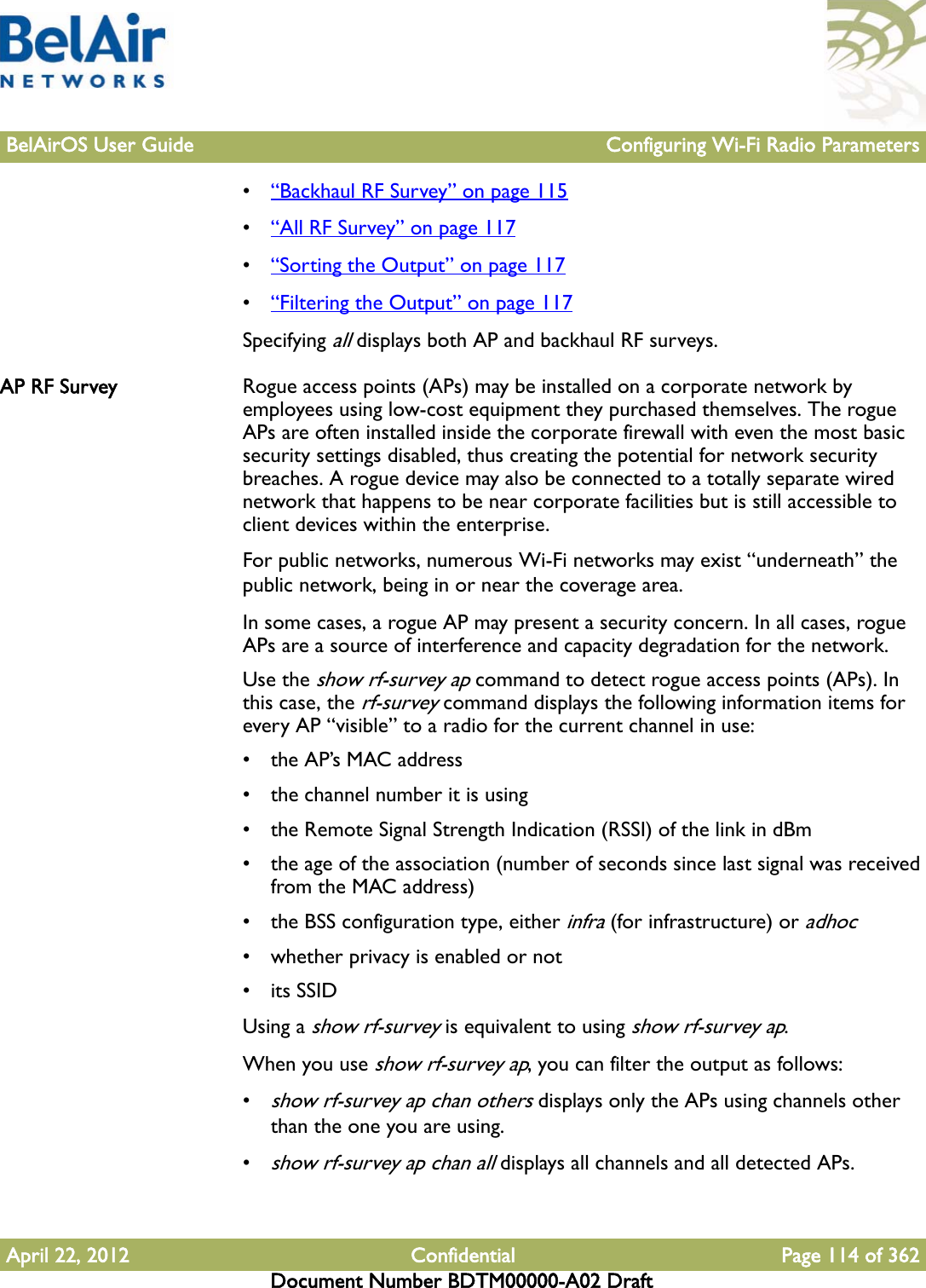
![BelAirOS User Guide Configuring Wi-Fi Radio ParametersApril 22, 2012 Confidential Page 113 of 362Document Number BDTM00000-A02 DraftBy default, enhanced throughput is enabled.802.11n Aggregation/interface/wifi-<n>-<m>/set tx-aggr {enable|disable}This command applies to the HTM and DRU only.This command enables or disables transmit aggregation for the radio. Transmit aggregation is an 802.11n feature where multiple MSDUs or MPDUs are packed together to reduce the overhead and average them over multiple frames, thus increasing the user level data rate.The default setting is enable. Minimum Association Thresholds/interface/wifi-<n>-<m>/set rcv-rssi-filter {disabled | enabled accept <value> discard <value>}This command applies to the BelAir20, BelAir20E, BelAir20EO, BelAir100N, BelAir100SN, BelAir100SNE and BelAir2100. It defines RSSI thresholds used for client associations:• A device can associate only if its Received Signal Strength Indicator (RSSI) is equal or greater than the accept threshold.• A device is forced to disassociate if its RSSI is continuously weaker than the discard threshold.The accept value ranges from -40 to -100 dBm. The default value is -100 dBm.The discard value ranges from -70 to -106 dBm. The default value is -106 dBm.The accept threshold must be at least 6 dBm stronger than the discard threshold.Doing an RF Survey/interface/wifi-<n>-<m>/show rf-survey [{ap [chan {others|all}]| backhaul| all}] [mac {belair|others}] [sort mac]This command allows you to determine potential backhaul configuration problems or rogue access points. It displays several information items for all Wi-Fi radios it can currently detect.The output is different, depending on whether you specify ap or backhaul. See the following subsections for details:•“AP RF Survey” on page 114](https://usermanual.wiki/Ericsson-Wi-Fi/40005011.User-Manual/User-Guide-1698497-Page-113.png)
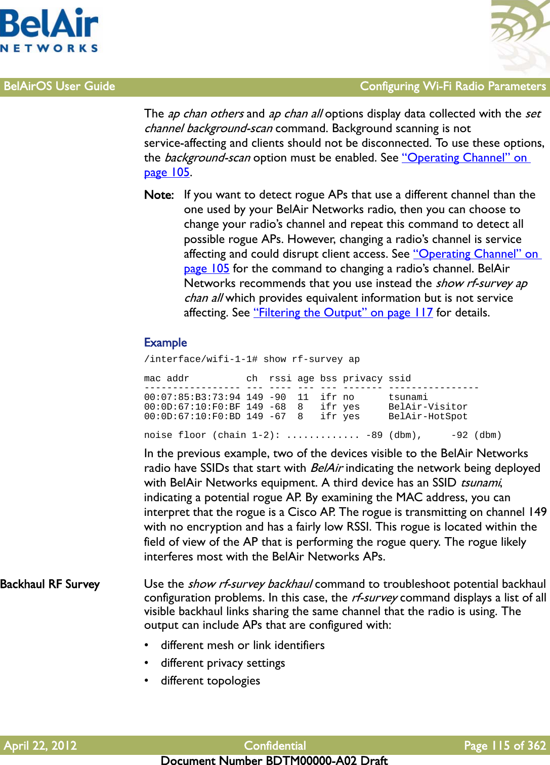
![BelAirOS User Guide Configuring Wi-Fi Radio ParametersApril 22, 2012 Confidential Page 116 of 362Document Number BDTM00000-A02 DraftThe output may show undef as the type of privacy, meaning that the AP cannot determine the type of privacy used by that link.Example 1 - Point-to-point Topology/interface/wifi-4-1# show rf-survey backhaulmac ch rssi age priv topo role linkIdx identifier state role identifier (dbm) (s) [S] [S] 12345678 [S] [M] [M] [M]----------------- -- ---- --- ---- ---- ---- -------- ---------------------- ----- ---- ------------00:0D:67:08:63:31 157 -42 0 none p2p -- -------- BelAirNetworks dis noise floor (chain 1-2): ............. -86 (dbm), -91 (dbm)Example 2 - Multipoint-to-multipoint Topology/interface/wifi-3-1# show rf-survey backhaulmac ch rssi age priv topo role linkIdx identifier state role identifier (dbm) (s) [S] [S] 12345678 [S] [M] [M] [M]----------------- -- ---- --- ---- ---- ---- -------- ---------------------- ----- ---- ------------00:0D:67:00:B3:55 167 -76 0 aes mesh -- -------- BelAirNetworks dis 00:0D:67:00:C9:A8 167 -58 0 aes mesh -- -------- BelAirNetworks dis 00:0D:67:00:E3:A3 167 -52 0 aes mesh -- -------- BelAirNetworks dis noise floor (chain 1-2): ............. -86 (dbm), -91 (dbm)Example 3 - Point-to-multipoint Topology, Base StationThis example shows a backhaul RF survey from an AP that is a stationary base station connected to two stationary subscriber stations. The AP also sees another AP but does not make a connection to it due to different topology (p2p)./interface/wifi-2-1# show rf-survey backhaulmac ch rssi age priv topo role linkIdx identifier state role identifier (dbm) (s) [S] [S] 12345678 [S] [M] [M] [M]----------------- -- ---- --- ---- ---- ---- -------- ---------------------- ----- ---- ------------00:0D:67:00:49:EA 167 -52 0 aes star ss 1------- BelAirNetworks dis 00:0D:67:00:B3:55 167 -90 0 aes p2p -- -------- BelAirNetworks dis 00:0D:67:00:C9:A8 167 -75 0 aes star ss --1----- BelAirNetworks dis noise floor (chain 1-2): ............. -86 (dbm), -91 (dbm)Example 4 - Point-to-multipoint Topology, Subscriber StationThis example shows a backhaul RF survey from one of the stationary subscriber stations of Example 3./interface/wifi-2-1# show rf-survey backhaulmac ch rssi age priv topo role linkIdx identifier state role identifier (dbm) (s) [S] [S] 12345678 [S] [M] [M] [M]----------------- -- ---- --- ---- ---- ---- -------- ---------------------- ----- ---- ------------00:0D:67:00:B3:55 167 -73 0 aes star bs 111----- BelAirNetworks dis 00:0D:67:00:C9:A8 167 -58 0 aes p2p -- -------- BelAirNetworks dis 00:0D:67:00:E3:A3 167 -53 0 aes star bs --1----- BelAirNetworks dis noise floor (chain 1-2): ............. -86 (dbm), -91 (dbm)](https://usermanual.wiki/Ericsson-Wi-Fi/40005011.User-Manual/User-Guide-1698497-Page-116.png)
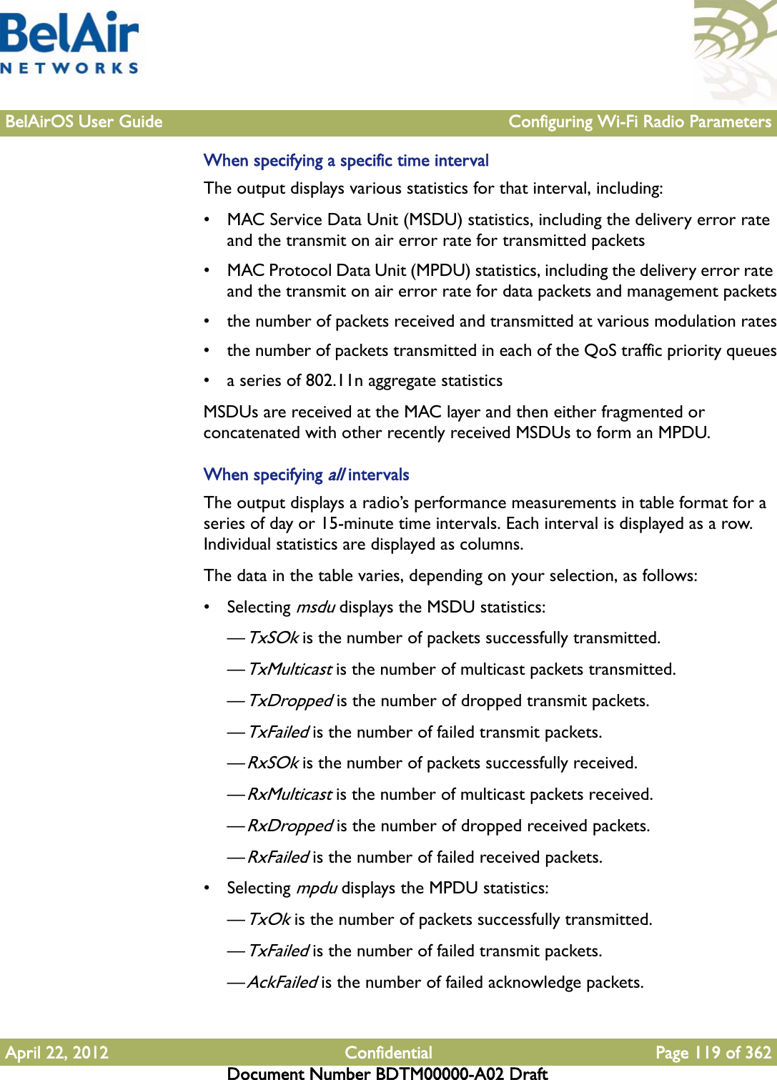
![BelAirOS User Guide Configuring Wi-Fi Radio ParametersApril 22, 2012 Confidential Page 117 of 362Document Number BDTM00000-A02 DraftExample 5 - Mobile Backhaul Mesh LinksThis example shows a backhaul RF survey for an AP providing mobile backhaul mesh links. /interface/wifi-2-1# show rf-survey backhaulmac ch rssi age priv topo role linkIdx identifier state role identifier (dbm) (s) [S] [S] 12345678 [S] [M] [M] [M]----------------- -- ---- --- ---- ---- ---- -------- ---------------------- ----- ---- ------------00:0D:67:00:C9:A8 167 -79 0 aes -- -- -------- BelAirNetworks ena ss mtest100:0D:67:00:49:EA 167 -66 0 aes mesh -- -------- BelAirNetworks ena bs mtest100:0D:67:00:E3:A3 167 -80 0 aes mesh -- -------- BelAirNetworks ena bs mtest1noise floor (chain 1-2): ............. -86 (dbm), -91 (dbm)All RF Survey Use the show rf-survey all command to display a list of all visible backhaul links and all visible APs, except those sharing the same channel that the radio is using.Filtering the Output The mac option allows you to filter the output:•mac belair displays only BelAir Networks APs; that is, only devices with BelAir Networks MAC addresses•mac others displays only APs that do not have BelAir Networks MAC addresses.Sorting the Output Use the sort mac option to sort the output in descending order by MAC address.Changing Wi-Fi Interface Admin State/interface/wifi-<n>-<m>/set admin-state {enable|disable}This command controls the state of the Wi-Fi interface including all links. When set to enable, the Wi-Fi interface is in the operational state. When set to disable, the Wi-Fi interface and all associated functions are disabled. The default is disabled.Use the /interface/wifi-<n>-<m>/show config command to view the current admin state of the Wi-Fi interface.Wi-Fi Interface Statistics/interface/wifi-<n>-<m>/show statisticsThis command displays the statistics for a Wi-Fi interface.Example/interface/wifi-1-1# show statisticsMSDU Statistics: RX: .................. 0 TX: .................. 133805](https://usermanual.wiki/Ericsson-Wi-Fi/40005011.User-Manual/User-Guide-1698497-Page-117.png)
![BelAirOS User Guide Configuring Wi-Fi Radio ParametersApril 22, 2012 Confidential Page 118 of 362Document Number BDTM00000-A02 Draft RX Mcast: ............ 0 TX Mcast: ............ 133805 Access Rx Fail Rate (frames/min): 0 Access Rx Dup Rate (frames/min): 0 Access Rx OOR Rate (frames/min): 0 Access Tx Fail Rate (frames/min): 0MPDU Statistics: RX: .................. 17694466 TX: ................. 1104110 FCS Errors: .......... 0 WEP Undecryptable: ... 0 RTS Success: ......... 235053 RTS Failures: ........ 0 ACK Failures: ........ 0 Failed: .............. 0 Retries: ............. 0 Multiple Retries: .... 0 Frame Dups: .......... 0Privacy Rejected Statistics: Transmit: ............ 0 Plain: ............... 0 Encrypted: ........... 0 No Key: .............. 0DoS Statistics: deauth attacks: ...... 0Backhaul Link Statistics:Link Rx_Pkts Tx_Pkts Rx_Bytes Tx_Bytes Rx_Errs Tx_Errs---- ------- ------- -------- -------- ------- -------1 131828 405913 15326450 35360815 0 0Wi-Fi Performance Monitoring Statistics/interface/wifi-<n>-<m>/show pm {fifteen-min|day} [{<0-96>|<0-7>|all{msdu|mpdu|error-rate| rx-modulation|tx-modulation|aggr|duty-cycle}}]This command displays a radio’s performance measurements either for a specific time interval or for a series of time intervals. The valid parameter options are:•fifteen-min, fifteen-min 0 to fifteen-min 96, fifteen all msdu, fifteen all mpdu, fifteen all error-rate, fifteen all rx-modulation, fifteen all tx-modulation or fifteen all aggr•day, day 0 to day 7, day all msdu, day all mpdu, day all error-rate, day all rx-modulation, day all tx-modulation or day all aggrNote: Depending on the type and vintage of radio, not all statistics may be available.Specifying fifteen-min is equivalent to specifying fifteen-min 0 and means the current 15-minute interval. Specifying day is equivalent to specifying day 0 and means the current day, excluding data from the current 15-minute period.](https://usermanual.wiki/Ericsson-Wi-Fi/40005011.User-Manual/User-Guide-1698497-Page-118.png)
![BelAirOS User Guide Configuring Wi-Fi Access Point ParametersApril 22, 2012 Confidential Page 124 of 362Document Number BDTM00000-A02 Draft•“ARP Filtering” on page 143•“ARP to Unicast Conversion” on page 143•“802.11b Protection” on page 144•“Wi-Fi Client Statistics” on page 144See also:•“Configuring Wi-Fi Radio Parameters” on page 103•“Wi-Fi AP Security” on page 146•“Wi-Fi Backhaul Link Configuration” on page 161•“Mobile Backhaul Mesh” on page 169Displaying AP ConfigurationUse the show config access command to display the current AP configuration. See “Displaying Wi-Fi Radio Configuration” on page 104 for details.Example - BelAir20E/interface/wifi-1-1# show config accessSlot: 1, Card Type: htme, revision: 1, Port: 1, Radio: HTMv1 5GHz 802.11nadmin state: ................. Enabledchannel: ..................... 149 mode: ...................... ht40plus mimo: ...................... 3x3 tx power: .................. 18.0 (dBm per-chain), 23.0 (dBm total)antenna location: ............ External Portantenna index: ............... 1antenna gain: ................ 5.0 (dBi)link distance: ............... 1 (km)base radio MAC : ............. 00:0d:67:0c:21:90Access: AP admin state: ............ Enabled secure addresses (vlan): ... none client blacklist: .......... none dhcp unicast: .............. Disabled deauth dos defense: ........ Disabled client auth trap: .......... DisabledMisc: rts-cts threshold: ......... 100 broadcast filter status: ... Disabled broadcast filter rate: ..... 200AP Custom Rates /interface/wifi-<n>-<m>/show custom-rates/interface/wifi-<n>-<m>/set custom-rates {disabled | enabled [{add|del} [b <rate_string>] [g <rate_string>] [ht <rate_string>]}](https://usermanual.wiki/Ericsson-Wi-Fi/40005011.User-Manual/User-Guide-1698497-Page-124.png)
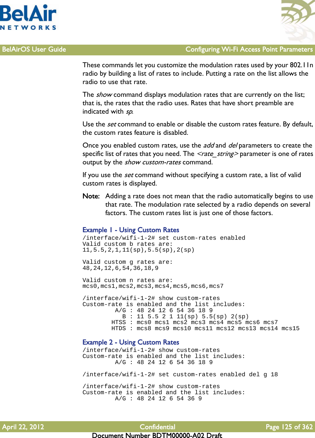
![BelAirOS User Guide Configuring Wi-Fi Access Point ParametersApril 22, 2012 Confidential Page 126 of 362Document Number BDTM00000-A02 DraftDisplaying Associated Wireless Clients/interface/wifi-<n>-<m>/show clients [ssid <ssid_index>] This command displays the list of associated wireless clients for a given SSID. If no SSID is specified, the displayed list shows all associated clients and their SSID.The ssid_index parameter must be a valid SSID index.In the resulting output:• The time field displays how long the client has been associated to the BelAir Networks radio. • The IP field lists the client's IP address. (s) indicates static IP addressing.• The identity field lists the 802.1X client identity. It is present for dot1x or WPA SSIDs.• The auth field lists the authentication state of the client. See Tab l e 9 .• The dhcp field lists the client DHCP state (applicable only if client uses dynamic IP addressing). See Table 10 on page 126. Table 9: Auth Field Value Descriptions Value Descriptionunauth default or initial stateauth client is authorized for Open or WEP privacyeapAuth client is authorized for dot1x, WPA1 or WPA2 privacypskErr Possible wrong WPAPSK key configured on clientradto For dot1x, WPA1 or WPA2. Problems connecting to radius server, possibly because of a network problem.cltto For dot1x, WPA1 or WPA2. Problems sending EAP packets to client.Table 10: DHCP Field Value Descriptions Value Descriptioninit Client has just connected and has not yet started a DHCP sequence](https://usermanual.wiki/Ericsson-Wi-Fi/40005011.User-Manual/User-Guide-1698497-Page-126.png)
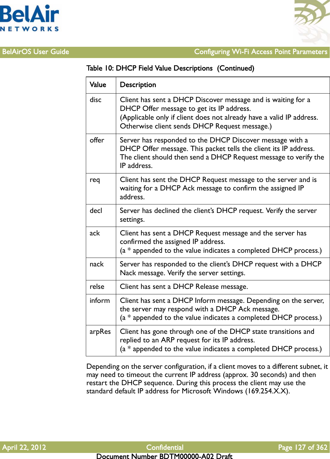
![BelAirOS User Guide Configuring Wi-Fi Access Point ParametersApril 22, 2012 Confidential Page 128 of 362Document Number BDTM00000-A02 DraftExample/interface/wifi-2-1# show clientsSS-ID vlan mac addr time IP identity rssi auth dhcp----- ---- ----------------- ---- ------------------ ---------- ---- ------- ------2-4 0 00:11:24:26:24:AA 4m 10.9.9.20(s) -82 eapAuth staticDisplaying Wireless Client Details/interface/wifi-<n>-<m>/show client <1|2|...|2007> [throughput] [stats]This command displays the details of a wireless client that is associated or was recently associated with the AP. You determine the client number <1|2|...|2007> with the show clients command. See “Displaying Associated Wireless Clients” on page 126. The throughput parameter displays additional information on traffic throughput. The stats parameter allows displays additional information on packet statistics. In the resulting output, the age parameter shows the time since the radio last received a data frame from the client and the state parameter shows authenticated (2) if the client is no longer associated.Example/interface/wifi-1-1# show client 35 Ssid: ........... 1 Vlan: ........... 0 Mac Address: .... 00:18:DE:98:28:E8 Connected Time: . 0 yrs 0 days 00:00:42 Aging Time: ..... 0 seconds Ip Address: ..... 10.1.1.60 Identity: ....... Rssi: ........... -48 (dBm) Auth State: ..... Authenticated(open/wep) Dhcp State: ..... Client sent ARP response (complete)Disconnecting a Wireless Client/interface/wifi-<n>-<m>/disconnect client <mac_address>This command lets you disconnect the specified client from the AP. You determine the client MAC address with the show clients command. See “Displaying Associated Wireless Clients” on page 126.](https://usermanual.wiki/Ericsson-Wi-Fi/40005011.User-Manual/User-Guide-1698497-Page-128.png)
![BelAirOS User Guide Configuring Wi-Fi Access Point ParametersApril 22, 2012 Confidential Page 129 of 362Document Number BDTM00000-A02 DraftWireless Client Load Balancing/interface/wifi-<n>-<m>/set max-num-clients <max_num> [strict]This command lets you set the maximum number of clients that can associate with the AP. Once the maximum is reached, new client associations are not immediately accepted.While using this command, keep in mind the following:• If you do not use the strict parameter, and a new client continues to try to associate after the client maximum is reached, the AP does accept it after three retries. (All association retries in a one minute interval is considered a single retry.) • If you use the strict parameter, the AP does not accept a new client when the client maximum is reached, even if the new client to tries to associate repeatedly.• Changing the client maximum does not take effect until two minutes later.• Changing the client maximum does not disconnect any existing client.The <max_num> parameter ranges from 0 to 256. The default is 256.Configuring RTS-CTS Handshaking/interface/wifi-<n>-<m>/set rts-cts {disabled|enabled <threshold>}This command lets you enable or disable Request-to-Send (RTS) and Clear-to-Send (CTS) handshaking. When enabled, handshaking occurs for packets larger than the threshold. The <threshold> parameter can range from 1 to 65536. The default value is 100.By default, dynamic rate handshaking is disabled.Specifying the Beacon Period/interface/wifi-<n>-<m>/set beacon-period {auto | <bp_value> [dtim <dt_value>]}This command lets you specify the behavior of your beacon period for broadcast Service Set Identifiers (SSIDs). See also “AP Service Set Identifiers” on page 131.If specified, the <bp_value> parameter specifies a fixed beacon period in milliseconds. It ranges from 100 to 400. The optional <dt_value> parameter specifies the DTIM value. It ranges from 1 to 3.](https://usermanual.wiki/Ericsson-Wi-Fi/40005011.User-Manual/User-Guide-1698497-Page-129.png)
![BelAirOS User Guide Configuring Wi-Fi Access Point ParametersApril 22, 2012 Confidential Page 130 of 362Document Number BDTM00000-A02 DraftIf you select auto, the AP automatically adjusts the beacon period and DTIM value dynamically according to the number of MBSSIDs.The default setting is to have a fixed beacon period of 100 ms with a DTIM value of 3.Displaying Client Association Records/interface/show client-record <num_entries> [radio <radioIf_name>] [vlan {<vlan_id>| none}] [mac-addr <mac_address>] [aggregation | start <start_idx>]/interface/show client-record detail <num_entries>Every 15 minutes, the AP generates wireless client association records. A client record includes the following information:• The IP address, MAC address, VLAN, RSSI, DHCP state, and authentication state of the client.• The radio interface and SSID index for the radio the Wi-Fi client is associated to.• The start and end connection time, as well as the times a client has a throughput greater than 2 kBps or transmits more than 2 kB of traffic.If a client connection crosses more than one 15-minute interval, another client record is generated for that client. A continue flag indicates that the client has another record in the next 15-minute interval. The num_entries parameter specifies the number of entries to display.You can filter the output based on the following optional parameters:•Use radio <radioIf_name> to filter for records of clients connected to a particular Wi-FI interface, such as wifi-2-1. •Use vlan <vlan_id> to filter for records of clients using a particular VLAN, or no VLAN.•Use mac-addr <mac_address> to filter for records with a client’s MAC address. •Use aggregation to show combined client records when a client connection crosses multiple 15-min boundary. Use start <start_idx> to show client records starting from a particular record index number. The starting index number is always unique.Use the show client-record detail command to display details of a particular client record.](https://usermanual.wiki/Ericsson-Wi-Fi/40005011.User-Manual/User-Guide-1698497-Page-130.png)
![BelAirOS User Guide Configuring Wi-Fi Access Point ParametersApril 22, 2012 Confidential Page 131 of 362Document Number BDTM00000-A02 DraftExample - Non Aggregated Records/interface# show client-record 4 SSID Start Time Connect IP MAC RSSI Vlan RX TX Continue ID Radio INX dd hh:mm:ss mm:ss address address max avg min Id KB KB flag 11 wifi-2-1 1 11 06:42:57 15:02 10:1:1:7 00:18:de:c2:30:46 -25 -44 -64 0 90 109 Yes 10 wifi-2-1 1 11 06:27:55 15:02 10:1:1:7 00:18:de:c2:30:46 -25 -44 -64 0 60 72 Yes 9 wifi-2-1 1 11 06:12:53 15:02 10:1:1:7 00:18:de:c2:30:46 -25 -44 -64 0 268 323 Yes 8 wifi-2-1 1 11 05:57:51 15:02 10:1:1:7 00:18:de:c2:30:46 -25 -44 -64 0 219 250 YesExample - Aggregated Records/interface# show client-record 20 aggregation SSID Start Time End Time IP MAC RSSI Vlan RX TX Cross Byte Cross Rate ID Radio INX dd hh:mm:ss dd hh:mm:ss address address avg Id KB KB dd hh:mm:ss dd hh:mm:ss 1 wifi-2-1 1 11 04:57:41 11 04:59:40 10:1:1:7 00:18:de:c2:30:46 -42 0 5 4 11 04:58:42 not exceed 3 wifi-2-1 1 11 05:00:11 11 05:01:25 10:1:1:7 00:18:de:c2:30:46 -45 0 11 8 11 05:00:52 not exceed 4 wifi-2-1 1 11 05:08:02 11 06:57:59 10:1:1:7 00:18:de:c2:30:46 -44 0 1074 1255 11 05:08:21 not exceedExample - Client Record DetailFigure 14: Client Record Detail Example Changing AP Admin State/interface/wifi-<n>-<m>/set ap admin-state {enable|disable}This command controls the state of the AP. When set to enable, the AP is in the operational state. When set to disable, the AP and all associated functions are disabled. The default is enabled.AP Service Set IdentifiersUse the commands in this section to:• configure AP Service Set Identifiers (SSIDs)• map an SSID to a VLAN/interface# show client-record detail 4Client Record INX[4]: Radio Interface: wifi-2-1 SSID Idx: 1 Start Time (mon-dd hh:mm:ss): 07-11 05:08:02 End Time (mon-dd hh:mm:ss): 07-11 05:12:45 Vlan ID: 0 IP Address: 10:1:1:7 MAC Address: 00:18:de:c2:30:46 RSSI(dbm): max -25, min -64, avg -43 Exceed Throughput(2KB) Time: 07-11 05:08:21 Throughput: Rx 35KB, Tx 33KB Authenticate State: Authenticated(open/wep) DHCP State: Client sent ARP response Is Continued: YesWhen the client logged inWhen the record endsClient RSSI informationTime when client crossed the 2 kbyte threshold.Same as show client detail command.If Yes, record continues into next 15-minute window.](https://usermanual.wiki/Ericsson-Wi-Fi/40005011.User-Manual/User-Guide-1698497-Page-131.png)
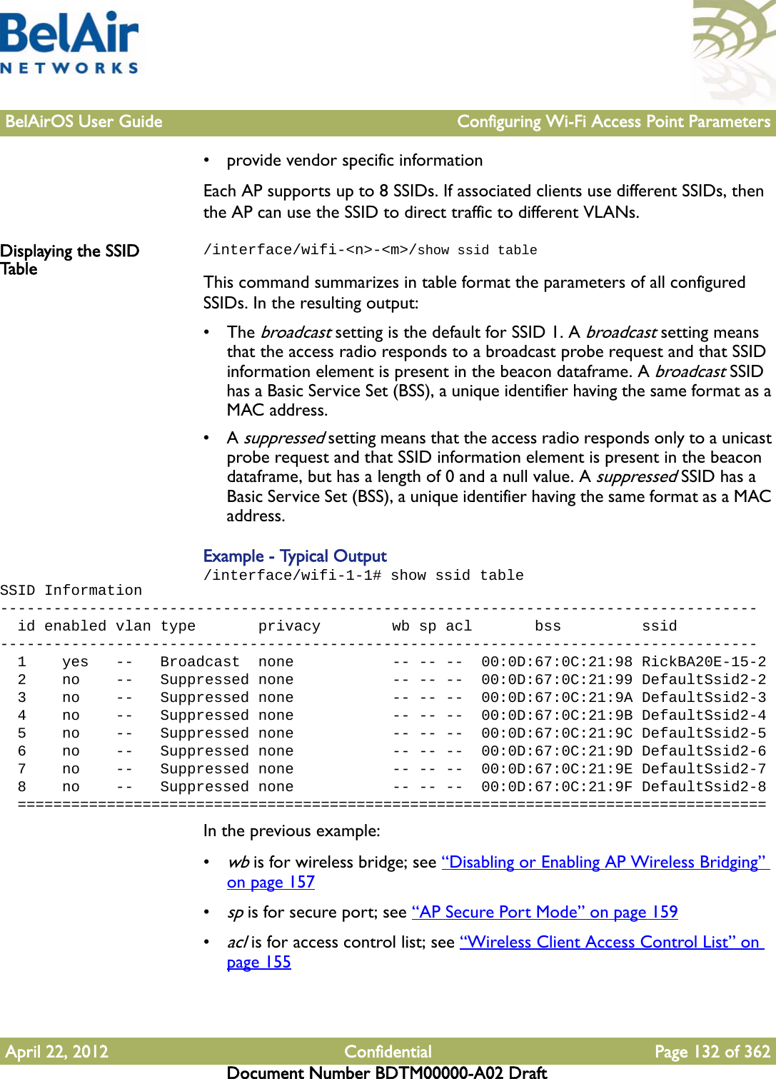
![BelAirOS User Guide Configuring Wi-Fi Access Point ParametersApril 22, 2012 Confidential Page 133 of 362Document Number BDTM00000-A02 Draft•bss is for basic service set; see “Configuring SSIDs” on page 134• a star ( * ) means that the feature is enabled for that particular SSID• a double dash ( -- ) means that the feature is not enabled for that particular SSIDDisplaying SSID Details /interface/wifi-<n>-<m>/show ssid <ssid_index> configThis command displays details of a particular SSID. Use the show ssid table command to determine <ssid_index>.Example/interface/wifi-1-1# show ssid 3 configConfiguration for ssid 3admin state: ..................... EnabledSSID: ............................ DefaultSsid2-1AP oos identifier: ............... outOfService..mbssid state: .................... Enabledtype: ............................ Broadcastprivacy mode: .................... nonerekey: ........................... Disabledkey strict: ...................... notraffic mapped to vlan: .......... nonepassthrough vlan(s): ............. disabledwireless bridge state: ........... Disabledgroup address filter: ............ noneupstream UP marking: ............. Disabled (0)acl state: ....................... Disabledsecure port state: ............... Disabledarp unicast conversion state: .... Disabledradius NAS identifier: ........... belairradius accounting: ............... Disabledradius station id unformatting: .. Disabledradius account session id: ....... Disabledsecure addresses (vlan): No secure addresses configuredclient blacklist: No blacklist entriesauto secure gateway: ............. enabled Address Vlan 00:0a:5e:49:1c:33 (500) 00:0a:5e:49:1c:8b (600)radius servers: No radius servers configured for this ssidDHCP relay servers: Server[1] Addr: 10.1.100.88 sub-option: 150/151 inserted sub-option151: vpn-selectorOption82 Insert Enabled.Default Management SSID By default, SSID 8 of each radio is a suppressed SSID preconfigured for a management session.](https://usermanual.wiki/Ericsson-Wi-Fi/40005011.User-Manual/User-Guide-1698497-Page-133.png)
![BelAirOS User Guide Configuring Wi-Fi Access Point ParametersApril 22, 2012 Confidential Page 134 of 362Document Number BDTM00000-A02 DraftThe default management SSID is BelAir-<MAC_info>, where <MAC_info> is the last six digits of the AP’s MAC address.For example, if an AP has a MAC address of 00:0D:67:08:48:98, the default management SSID is BelAir-084896. By default, SSID 8:• uses WPA encryption with the following pre-shared key: DefaultKey123. Users may wish to change the security settings to suit their needs.• is not mapped to a VLAN. Users may wish to map SSID 8 to a separate VLAN reserved for management sessions.Refer to the following topics for details on changing the default settings for SSID 8:• To change the SSID and map it to a VLAN, see “Configuring SSIDs” on page 134.• To change the security settings, see “Wi-Fi AP Security” on page 146.Configuring SSIDs /interface/wifi-<n>-<m>/set ssid <ssid_index> service-set-identifier <ssid_string> {broadcast | suppressed} vlan {<vlanID-list>|none} [passthrough-vlan {<passvlanID-list>|none}]This command allows you to configure AP SSIDs.The ssid_string parameter is the SSID setting. SSIDs are case sensitive and can contain up to 32 alphanumeric characters. To specify a blank string, input two double quotes (““).The ssid_index parameter is an integer from 1 to 8. Use the show ssid table command to determine <ssid_index>.For a description of the broadcast and suppressed parameters, see “Displaying the SSID Table” on page 132.The vlanID-list parameter, if present, specifies a comma separated list of VLAN IDs. Each VLAN ID must be an integer from 1 to 3015 and from 3018 to 4045. The list can contain up to eight VLAN IDs.The vlanID-list parameter activates functionality to balance traffic among up to eight VLANs, based on the last three bits of the MAC address of the wireless client generating the traffic. The last three bits of the MAC address can range in value from 0 to 7. For example:](https://usermanual.wiki/Ericsson-Wi-Fi/40005011.User-Manual/User-Guide-1698497-Page-134.png)
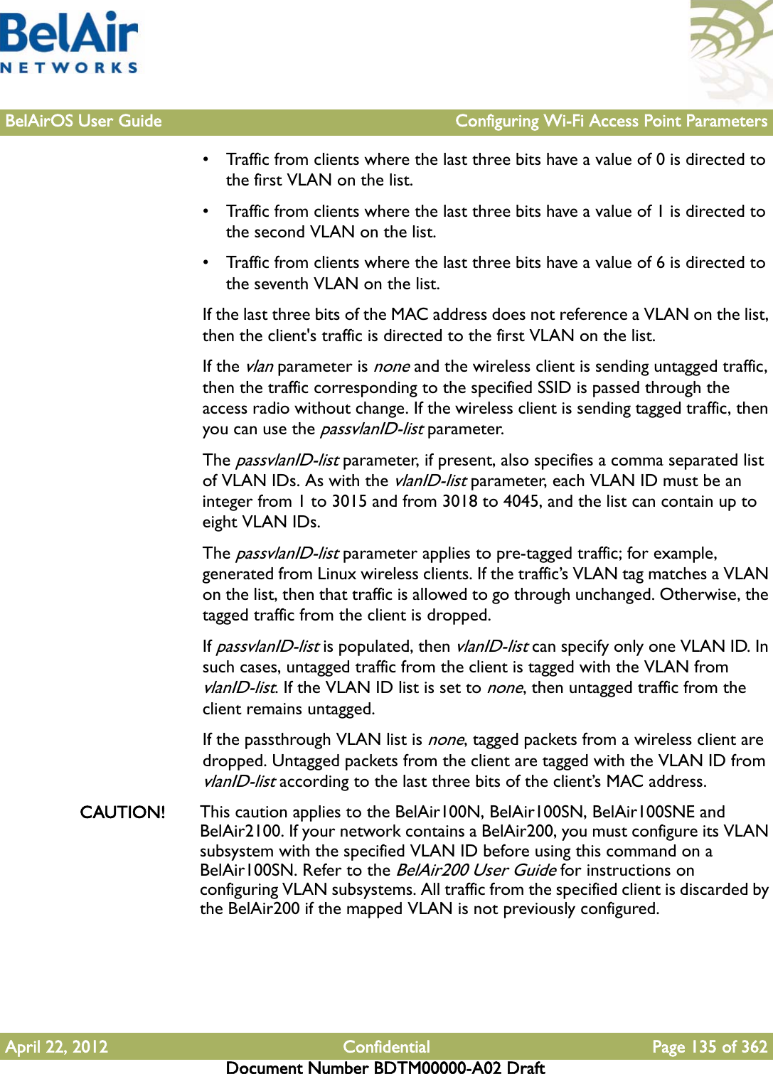
![BelAirOS User Guide Configuring Wi-Fi Access Point ParametersApril 22, 2012 Confidential Page 136 of 362Document Number BDTM00000-A02 DraftUpstream User Priority Marking/interface/wifi-<n>-<m>/set ssid <ssid_index> upstream-up-marking {enabled|disabled} [ up-value <val> ]This command enables or disables the ability to set the User Priority (UP) value of any packet received by the AP for a particular SSID. The UP values are then used throughout the network to separate and prioritize traffic through Quality of Service (QoS) settings. See “Quality of Service Settings” on page 225 for details. By default, upstream UP marking is disabled.The ssid_index parameter must be a valid SSID index. See “AP Service Set Identifiers” on page 131Setting Traffic Limits /interface/wifi-<n>-<m>/set ssid <ssid_index> traffic-limit ([upstream <bits-per-second>] [downstream <bits-per-second>])This command allows you to control the amount of traffic the AP sends for a particular SSID:•Use the upstream parameter to specify the amount sent to the network. •Use the downstream parameter to specify the amount sent to wireless clients. • Specify 0 to remove previously set limits.Use the show ssid table command to determine <ssid_index>. Use the show ssid <ssid_index> config command to see the currently configured values.Limiting the Number of Clients per SSID/interface/wifi-<n>-<m>/set ssid <ssid_index> client-limit-priority <priority-number> [min <minimum-guaranteed>] [max <maximum-allowed>]This command allows you to control the number of clients that a particular SSID can service. The sum of all clients for all SSIDs cannot exceed the limit set with the set max-num-clients <max_num> command. (See “Wireless Client Load Balancing” on page 129.)The associated parameters are:•Use <priority-number> to assign a priority number to the SSID. Priority numbers range from 1 to 8, where 8 is the highest priority. The default priority is 1.](https://usermanual.wiki/Ericsson-Wi-Fi/40005011.User-Manual/User-Guide-1698497-Page-136.png)
![BelAirOS User Guide Configuring Wi-Fi Access Point ParametersApril 22, 2012 Confidential Page 137 of 362Document Number BDTM00000-A02 Draft•Use the min parameter to specify the minimum number of clients this SSID is guaranteed to serve. The default setting is 0.•Use the max parameter to specify the maximum number of clients this SSID can have. The default setting is 256.Use the show ssid table command to determine <ssid_index>. Use the show ssid <ssid_index> config command to see the currently configured values.Providing Vendor Specific Information/interface/wifi-<n>-<m>/set ssid <ssid-number> option82 insertion {enabled|disabled}/interface/wifi-<n>-<m>/set ssid <ssid-number> option82 use ([circuit-id {enabled | disabled}] [remote-id {enabled | disabled}] [vendor-option {enabled | disabled}] [scope-selector {enabled | disabled}])/interface/wifi-<n>-<m>/set ssid <ssid-number> option82-circuit-id {SSID | custom-field <num_str>}/interface/wifi-<n>-<m>/set ssid <ssid-number> option82-remote-id {node-mac | custom-field <num_str>}/interface/wifi-<n>-<m>/set ssid <ssid-number> option82-scope-selector <random_str>For any SSID, you can add vendor specific option 82 information to DHCP packets. Typically, this is done when DHCP relay functionality is enabled with the set ssid <ssid_index> dhcp-relay command. (For details see “Assigning SSID Traffic to Use DHCP Relay” on page 193.) However, vendor specific information can be added even if DHCP relay is disabled. In such cases, a warning is displayed but the vendor specific information is still added to the packets.Use the set ssid option82 insertion command to control whether DHCP option 82 (DHCP relay agent information) is inserted into packets or not. Relay agent information can be packaged in the following option 82 suboption fields:• Circuit ID; that is, suboption 1• Remote ID; that is, suboption 2• Vendor option; that is, suboption 9• Scope selector; that is, suboptions 150 and 151If option 82 insertion is enabled, use the set ssid option82 use command to control which fields (circuit ID, remote ID, vendor option, or scope selector) are used. You can use any or all of these fields.](https://usermanual.wiki/Ericsson-Wi-Fi/40005011.User-Manual/User-Guide-1698497-Page-137.png)
![BelAirOS User Guide Configuring Wi-Fi Access Point ParametersApril 22, 2012 Confidential Page 139 of 362Document Number BDTM00000-A02 Draft• Suboption 151. The VPN selection ID is packaged as follows:0x97, 0x0a, 0x00, 0xnn, 0xnn, 0xnn, 0xnn, 0xnn, 0xnn, 0xnn, 0xnn, 0xnnWhere:—The first field is always 0x97, identifying Suboption 151.—The second field specifies the length of the VPN selection ID.—The remaining fields specify an ASCII string of the VPN selection ID.If Suboption 150 and 151 are selected, use the set ssid option82-scope-selector command to specify the VPN selection ID. You can specify an ASCII string of up to 32 alphanumeric characters. To specify a blank string, input two double quotes (““).If Suboption 150 and 151 are selected and a Suboption 151 string is undefined, the SSID string is used instead.Changing SSID Admin State/interface/wifi-<n>-<m>/set ssid <ssid_index> admin-state {enable|disable}This command enables or disables a particular SSID. Use the show ssid table command to determine <ssid_index>. The default is enabled for SSID 1 and disabled for all others.Wi-Fi SSID Performance Monitoring Statistics/interface/wifi-<n>-<m>/show ssid <ssid_index> pm {fifteen-min|day} [{<num_str>|all}]This command displays an SSID’s performance measurements either for a specific time interval or for a series of time intervals. This command applies to all non-WCS radios.The ssid_index parameter must be a valid SSID index. For details see “Configuring SSIDs” on page 134.The valid time parameter options are:•fifteen-min, fifteen-min 0 to fifteen-min 96, and fifteen-min all•day, day 0 to day 7, and day allNote: Depending on the type and vintage of radio, not all statistics may be available.](https://usermanual.wiki/Ericsson-Wi-Fi/40005011.User-Manual/User-Guide-1698497-Page-139.png)
![BelAirOS User Guide Configuring Wi-Fi Access Point ParametersApril 22, 2012 Confidential Page 140 of 362Document Number BDTM00000-A02 DraftSpecifying fifteen-min is equivalent to specifying fifteen-min 0 and means the current 15-minute interval. Specifying day is equivalent to specifying day 0 and means the current day, excluding data from the current 15-minute period.When specifying a specific time intervalThe output displays the following statistics for the specified SSID:•TxByte and RxBytes are the number of bytes sent and received.•NumberOfMacs is the number of unique client MAC addresses that have associated with the AP•NumberOfAssociations is the number of successful client associations•NumberOfAuthorized is the number of associated clients that have received at least 25,000 bytes of traffic from the AP.When specifying all intervalsThe output displays an SSID’s performance measurements in table format for a series of day or 15-minute time intervals. Each interval is displayed as a row. Individual statistics are displayed as columns.Example 1/interface/wifi-2-1# show ssid 1 pm fifteen-minSSID 1 Performance - Interval type: current 15 minute Interval number: 0 TxByte: 1589 RxBytes: 0 NumberOfMacss: 0 NumberOfAssociation:0 NumberOfAuthorized:0Example 2/interface/wifi-2-1# show ssid 1 pm fifteen-min allint TxBytes RxBytes NumberOfMacs NumberOfAssociation NumberOfAuthorized0 342 2188 0 1 01 10182662 63106 1 1 1Out-of-service Advertising/interface/wifi-<n>-<m>/set ssid <ssid-number> ap-oos-identifier <oos_string>/system/set ap-oos-broadcast-delay <oos_delay>/interface/wifi-<n>-<m>/set ap-oos-broadcast {enabled|disabled} [option {replace|prepend}]/system/show ap-oos-broadcast-delayThese commands let you modify the SSIDs of a radio with an out-of-service string when an AP loses its egress connection for longer than the period specified by <oos_delay>. The out-of-service string can be prepended to the existing SSID or it can replace the existing SSID. The out-of-service string can](https://usermanual.wiki/Ericsson-Wi-Fi/40005011.User-Manual/User-Guide-1698497-Page-140.png)
![BelAirOS User Guide Configuring Wi-Fi Access Point ParametersApril 22, 2012 Confidential Page 143 of 362Document Number BDTM00000-A02 DraftARP Filtering /interface/wifi-<n>-<m>/set arp-filtering {disabled|enabled}This command enables or disables ARP filtering on radio traffic from the AP to the wireless client. When enabled, the radio only forwards ARP request packets to a currently connected client. Otherwise, the downstream ARP requests are dropped.The default setting is disabled.ARP to Unicast Conversion/interface/wifi-<n>-<m>/show arp-unicast-table [vlan <vlan_id> ]/interface/wifi-<n>-<m>/set ssid <ssid_index> arp-unicast-conversion {enabled|disabled}These commands control the conversion of upstream ARP packets to unicast packets.When enabled, this feature intercepts ARP requests from wireless clients and sends them only to known gateway MAC addresses. ARP responses from the gateway are sent to the wireless client without interception and manipulation.When the AP starts, the ARP unicast conversion table is empty. So the first ARP packet from the client is sent out as is; no conversion happens. When the ARP response arrives, the AP records its information, including the unicast MAC address, in the conversion table. For the following ARP packets, the AP replaces the broadcast MAC address in the ARP packet with the unicast MAC address from the conversion table. When a conversion table entry is used, a 4-second response timer is started. If the ARP response arrives within 4 seconds, then the entry remains valid. Otherwise the entry is deemed invalid and removed from the table. Each entry is removed after 4 hours of inactivity.The table holds up to 128 entries. The default setting is disabled.Example/interface/wifi-1-2# show arp-unicast-table vlaid ip mac expire---------------------------------------------------------------- 5 10.1.5.53 00:10:18:27:bc:07 03:57:18 0 10.1.1.53 00:10:18:27:bc:07 03:59:32 90 10.1.90.53 00:10:18:27:bc:07 03:59:55](https://usermanual.wiki/Ericsson-Wi-Fi/40005011.User-Manual/User-Guide-1698497-Page-143.png)
![BelAirOS User Guide Configuring Wi-Fi Access Point ParametersApril 22, 2012 Confidential Page 144 of 362Document Number BDTM00000-A02 Draft802.11b Protection/interface/wifi-<n>-<m>/set b-protection {disabled|enabled}This command enables or disables 802.11b protection for the radio. Normally, an 802.11g AP uses CTS-to-self to interact with 802.11b APs. The transmitted packet is small, but in High Capacity and Interference environments the accumulated effect is a substantial performance penalty. This feature disables 802.11b protection for the radio, meaning that CTS-to-self are not sent and maximizing the throughput for wireless clients that operate in the 2.4 GHz range.This feature improves performance if there are only a few 802.11b clients present and they are not generating large amounts of traffic. If not, the 802.11b clients may generate substantial numbers of collisions and actually impair traffic.The default setting is enabled.Wi-Fi Client Statistics/interface/wifi-<n>-<m>/show client <ssidIdx-clientIdx> [throughput] [stats]/interface/wifi-<n>-<m>/clear client {all|<ssidIdx-clientIdx>}These commands display radio transmission statistics for a particular client.Use the show clients command to determine the <ssidIdx-clientIdx> parameter. See the “Displaying Associated Wireless Clients” on page 126 for details on the show clients command.In the output of the show client <ssidIdx-clientIdx> [throughput] [stats] command:• The Attempts column contains the number of packets for which the initial transmission attempt was made at the specified rate. • The Success column contains the number of packets for which transmission succeeded at the specified rate. • The Start Rate Change column contains the number of times the specified rate was changed to be the initial transmission rate.• The Tx Retries entry describes the number of times 0, 1 or more retries were required. • The Tx Failures entry indicates the number of packets which were placed on the air at least once but never acknowledged. • The Tx Dropped entry indicates the number of packets dropped without ever being transmitted (due to interference).](https://usermanual.wiki/Ericsson-Wi-Fi/40005011.User-Manual/User-Guide-1698497-Page-144.png)
![BelAirOS User Guide Wi-Fi AP SecurityApril 22, 2012 Confidential Page 150 of 362Document Number BDTM00000-A02 DraftManaging RADIUS Servers/protocol/radius/show servers/protocol/radius/set server <server_idx> <server_ip_address> <shared secret> [authport <server_port>] [acctport <radius_acc_port>] [interface <NAS IP address>] [timeout <seconds>] [reauthtime <seconds>]/protocol/radius/del server <server_idx>These commands let you manage the RADIUS server list used for authenticating wireless clients. The list can contain up to 16 RADIUS servers. After the list is configured, you can then assign which AP SSID uses which server on the list. See “Assigning SSIDs to RADIUS Servers” on page 151. By default, if a RADIUS server is unavailable, then the SSID uses the next RADIUS server in the list. You cannot delete a server if it is being used by an SSID.The server_ip address parameter specifies the IP address of the RADIUS server.The shared secret parameter specifies the password for access to the RADIUS server.The server_port parameter ranges from 0 to 65535. It specifies the UDP port number of the RADIUS server. The default is 1812.The radius_acc_port parameter ranges from 0 to 65535. It specifies the UDP port number for RADIUS accounting data. The default value is 1813.The NAS IP address parameter specifies the Network Access Server (NAS) IP address for the AP RADIUS client. It is used when the AP is configured with multiple IP interfaces and matches the interface used to communicate with the RA_TUNNEL_TYPE 64 Refer to “RADIUS Assigned VLAN” on page 152.RA_TUNNEL_MEDIUM_TYPE 65 Refer to “RADIUS Assigned VLAN” on page 152.RA_TUNNEL_PRIVATE_GROUP_ID 81 Refer to “RADIUS Assigned VLAN” on page 152.RA_CONNECT_INFO 77 Always CONNECT 11Mbps 802.11bRA_EAP_MESSAGE 79 EAP packetRA_MESSAGE_AUTHENTICATOR 80 Authentication string from RADIUS serverRA_INTERIM_INTERVAL 85 Not usedTable 11: RADIUS Attributes (Continued) Name ID Description](https://usermanual.wiki/Ericsson-Wi-Fi/40005011.User-Manual/User-Guide-1698497-Page-150.png)
![BelAirOS User Guide Wi-Fi AP SecurityApril 22, 2012 Confidential Page 151 of 362Document Number BDTM00000-A02 Draftgiven RADIUS server. The default value is the IP address of the AP’s management interface, which is usually the system’s default IP address.Note: The NAS IP address parameter is entered statically with this command. If the VLAN IP addresses are determined dynamically with a DHCP server, then an updated VLAN IP address is not automatically reflected into the NAS IP address parameter.The timeout parameter ranges from 2 to 300. It specifies the interval (in seconds) after which the RADIUS client considers that the remote server has timed out if a reply is not received. The default value is 10 seconds.The reauthtime parameter ranges from 0 to 50000000. It specifies the RADIUS re-authentication time (in seconds). This forces the AP to check all connected clients with the RADIUS server (that is, make sure they are still allowed to access the network) at the specified interval. You only need to configure this parameter if it is not specified on the RADIUS server. Setting the interval to zero disables this feature. The maximum interval time is 2147483647. If you enter a higher number, the value is set to its maximum.Example/protocol/radius# set server 3 172.16.1.20 my-secret12345 authport 1812 acctport 1813 interface 172.16.1.254 timeout 15 reauthtime 1Changing RADIUS Server Admin State/protocol/radius/set server-state <server_idx> {enable|disable}This command enables or disables a particular RADIUS server on the server list. Use the show servers command to determine <server_idx>. Assigning SSIDs to RADIUS Servers/interface/wifi-<n>-<m>/add ssid <ssid_index> radius-server <server_idx>/interface/wifi-<n>-<m>/del ssid <ssid_index> radius-server <server_idx>The add command specifies which RADIUS server to use to authenticate the specified SSID. The del command means that the specified RADIUS server stops authenticating the specified SSID. Use the /wifi-<n>-<m>/show ssid table command to determine <ssid_index>. Use the /radius/show servers command to determine <server_idx>.RADIUS Pre-authentication/interface/wifi-<n>-<m>/set ssid <ssid_index> radius-pre-auth {enabled|disabled} [delimiter {none|colon|dash}]This feature allows you to set up a centralized access control list at the RADIUS server instead of each AP. With this feature enabled, when an AP receives a client’s association request, it composes an access-request message](https://usermanual.wiki/Ericsson-Wi-Fi/40005011.User-Manual/User-Guide-1698497-Page-151.png)
![BelAirOS User Guide Wi-Fi AP SecurityApril 22, 2012 Confidential Page 153 of 362Document Number BDTM00000-A02 DraftRADIUS Accounting /interface/wifi-<n>-<m>/set ssid <ssid_index> radius ([accounting {enable|disable}] [nas-id <name>] [delimiter {none|colon|dash}] [append {none|ssid}]These commands let you manage RADIUS accounting for wireless clients.By default RADIUS accounting is disabled. The nas-id <name> parameters specify the RADIUS Network Access Server (NAS) identifier. The default value for <name> is belair.The delimiter parameter specifies whether the RADIUS packets use a colon (:), a dash (-) or nothing as a delimiter when specifying a MAC address.The append parameter specifies RADIUS station ID formatting. The default setting is ssid, meaning that the called-station-ID and the calling-station-ID fields are formatted to include SSID information to the provided MAC address.Client Authentication and De-authentication Trap/interface/wifi-<n>-<m>/set client-trap {enabled|disabled} [trap-delay {enabled|disabled}]This command controls whether a trap is sent for this particular radio whenever a wireless client authenticates or de-authenticates; that is, disconnects from the radio. The trap can be used by any Network Management System to monitor client activities. When the client trap is enabled and the trap delay is enabled, the trap is not sent out until 10 seconds after either of the following events:• the client connects and stays connected• the client is disconnected and stays disconnectedIf the trap delay is disabled, then the trap is sent out immediately after either of the previous events.When the client trap is disabled, the trap is not sent out.The default is to have both the client trap and trap delay enabled.AP Privacy /interface/wifi-<n>-<m>/set ssid <ssid_index> privacy {none|dot1x-open|wep40|wep104| {wpa {tkip|aes}}|wpa2 {tkip|aes}|wpa2mixed} [{psk <key-str>}|dot1x]](https://usermanual.wiki/Ericsson-Wi-Fi/40005011.User-Manual/User-Guide-1698497-Page-153.png)
![BelAirOS User Guide Wi-Fi AP SecurityApril 22, 2012 Confidential Page 154 of 362Document Number BDTM00000-A02 Draft [rekey {no|kpackets <count>|seconds <seconds>}] [strict {yes|no}]This command configures wireless privacy for a particular SSID. Use the show ssid table command to determine <ssid_index>. Use the show ssid <ssid_index> config command to show the current privacy settings.The dot1x-open parameter specifies an open privacy setting, but uses a RADIUS server for SSID authentication. The RADIUS server authenticates a wireless client by its username and password. After accepting the client, the RADIUS server does not provide encryption keys. The data transmission is open.WPA, WPA2 and WPA2mixed privacy uses TKIP or AES encryption. With WPA2mixed, the wireless client can use WPA or WPA2, and the AP accepts them both. The psk parameter specifies using a pre-shared key for authentication. When specifying the pre-shared key, note the following:•For wep40, the pre-shared key must be exactly 5 bytes. •For wep104 with psk, the pre-shared key must be exactly 13 bytes. •For wpa, wpa2 and wpa2mixed, the pre-shared key must be between 8 and 63 bytes long. The longer the key, the more secure the connection. • The pre-shared key can be specified as a hexadecimal number or ASCII string. Hexadecimal numbers must be preceded by 0X or 0x. ASCII strings must not contain the following characters: —bar (|)—semicolon (;)—question mark (?)—double quotation mark (“) The dot1x parameter specifies using RADIUS (EAP) authentication. You must pre-configure a list of RADIUS servers. See “RADIUS Servers for Wireless Clients” on page 148.The rekey parameter allows you to specify Group Key Rekey options to improve security. These options allow you to specify that a new group key (the key that is used for communication between the access radio and a group of clients) must be generated at regular intervals.](https://usermanual.wiki/Ericsson-Wi-Fi/40005011.User-Manual/User-Guide-1698497-Page-154.png)
![BelAirOS User Guide Wi-Fi AP SecurityApril 22, 2012 Confidential Page 155 of 362Document Number BDTM00000-A02 DraftThe default rekey setting is no meaning that the group key is not changed. If rekey is set to n seconds, the group key is changed after that time period. If rekey is set to n kpackets, the group key is changed after that many thousand packets. If strict is set to yes, the group key changes immediately when one client leaves the network. The default is no. The strict setting applies to wpa and wpa2 encryption only.Additional ConsiderationsMake sure to set the AP SSID to something other than the default before enabling wpa, wpa2 or wpa2mixed. The AP combines the password phrase with your SSID to create the key.Note: Some configuration commands take longer than others to be applied to a radio module. For example, it can take up to 40 seconds per SSID for a WPA PSK configuration to be applied to radio. The delay varies depending on the amount of computing resources required to implement the configuration.Wireless Client Blacklist/interface/wifi-<n>-<m>/add client blacklist <mac-addr>/interface/wifi-<n>-<m>/del client blacklist <mac-addr>These commands let you add and remove a MAC address from a client blacklist. If a wireless client’s MAC address matches an entry on the blacklist, the client cannot associate with the AP. The client blacklist can contain up to 16 entries. Each physical interface can have its own client blacklist.Use the show config access command to display the current client blacklist entries. Wireless Client Access Control List/interface/wifi-<n>-<m>/show ssid <ssid_index> acl [page <page-number> <page-size>]/interface/wifi-<n>-<m>/add ssid <ssid_index> acl-mac-address <mac-address>/interface/wifi-<n>-<m>/del ssid <ssid_index> acl-mac-address <mac-address>/interface/wifi-<n>-<m>/set ssid <ssid_index> acl {enabled|disabled}You can create a local list of clients (an ACL) that controls access to the network. The list can contain up to 16 clients per SSID. Clients are identified by the MAC address of their network card. If you have multiple APAP in your network, you need to create this list for every AP.](https://usermanual.wiki/Ericsson-Wi-Fi/40005011.User-Manual/User-Guide-1698497-Page-155.png)
![BelAirOS User Guide Wi-Fi AP SecurityApril 22, 2012 Confidential Page 158 of 362Document Number BDTM00000-A02 DraftDisabling Inter-AP Wireless Client CommunicationDisabling inter-AP wireless client communications involves setting up a secure MAC white list and enabling secure port mode for each AP.Secure MAC White List /interface/wifi-<n>-<m>/add secure-mac-address <mac-address-string> [secure-mac-mask <mac-mask-string>] [all | untagged | <vlan-id>]/interface/wifi-<n>-<m>/del secure-mac-address <mac-address-string> [all | untagged | <vlan-id>]Use these commands only if you want to manually provision the MAC addresses of the Internet gateway(s) or router(s) in your network.These commands add and remove a MAC address from the secure MAC white list. The MAC address can optionally be qualified with a mask and a traffic descriptor as follows:• The mask is specified with the secure-mac-mask option. Use ff to indicate bits to accept. Use 00 to indicate bits to ignore. For example, a MAC address of 00:0d:67:0c:21:90 with a mask of ff:ff:ff:00:00:00 specifies all MAC addresses beginning with 00:0d:67. You can also customize the mask to exactly suit your needs by using values other than ff or 00.• The traffic descriptor can be one of all, untagged or a VLAN ID. Use a VLAN ID to specify the traffic of a particular VLAN. Use untagged to specify only untagged traffic. Use all to specify all traffic.When configured in secure port mode, the AP forwards to the associated wireless clients only those Layer 2 (Ethernet) frames for which the source MAC address and VLAN matches an entry its white list. The white list can contain up to 32 entries. If a VLAN is not specified, it is assumed to have a value of zero.In effect, while in this mode the AP acts as a firewall for all Layer 2 frames arriving from inside the network for the wireless clients. The secure MAC white list should only contain the MAC addresses of the gateway interfaces. Thus, wireless clients associated to other APs in the network are prevented from communicating with locally associated clients.Note 1: The secure MAC white list is different from the list described in “Wireless Client Access Control List” on page 155. In a client ACL, only the listed MAC addresses are allowed to associate with an AP. The secure MAC white list controls data forwarding to the wireless clients from remote entities in the network.Note 2: If the gateway and DHCP servers on your networks are on different machines, you must put the MAC addresses of both machines on the secure MAC white list.](https://usermanual.wiki/Ericsson-Wi-Fi/40005011.User-Manual/User-Guide-1698497-Page-158.png)
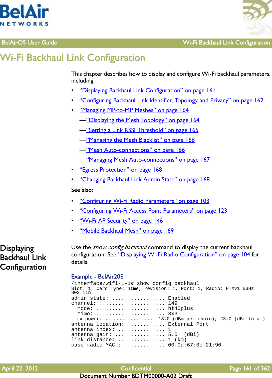
![BelAirOS User Guide Wi-Fi Backhaul Link ConfigurationApril 22, 2012 Confidential Page 162 of 362Document Number BDTM00000-A02 DraftCommon Backhaul: privacy: ................... AES key: ....................... mesh-min-rssi............... -100 (dbm)Stationary Backhaul: link admin state: .......... Disabled link id: ................... BelAirNetworks topology: .................. meshMobile Backhaul: mobile admin state: ........ Disabled mobile link id: ............ mobile link role: .......... ssBlacklist: No blacklist entriesLink Failure Detection: ...... DisabledBackhaul T1 Bandwidth limit:.. DisabledConfiguring Backhaul Link Identifier, To p o l o g y a n d Privacy/interface/wifi-<n>-<m>/set backhaul link ([identifier <link-id>] [topology {p2p|mesh|{star role {bs|ss} index <lnk_idx>}}] [privacy {{enabled key <pre_shared_key>}|disabled}])This command configures the backhaul link identifier, the backhaul topology and backhaul privacy.The backhaul link identifier identifies all members of a particular topology. The <link_id> parameter is case sensitive and can be up to 32 alphanumeric characters:• For Point-to-Point (P-to-P) links, BelAir Networks recommends that the link identifier describes the link; that is, the APs it connects. • For Point-to-Multipoint (P-to-MP) or Multipoint-to-Multipoint (MP-to-MP) links, the link identifier is also known as a mesh identifier. It is the same for all members of a particular mesh. A suitable link identifier is short phrase unique to the MP-to-MP mesh, for instance Company x Mesh A or Mesh Number 23.When configuring a particular topology, you must configure all members to have:• the same channel. Refer to “Operating Channel” on page 105 for the appropriate command• the same link identifier• the same privacy settings](https://usermanual.wiki/Ericsson-Wi-Fi/40005011.User-Manual/User-Guide-1698497-Page-162.png)
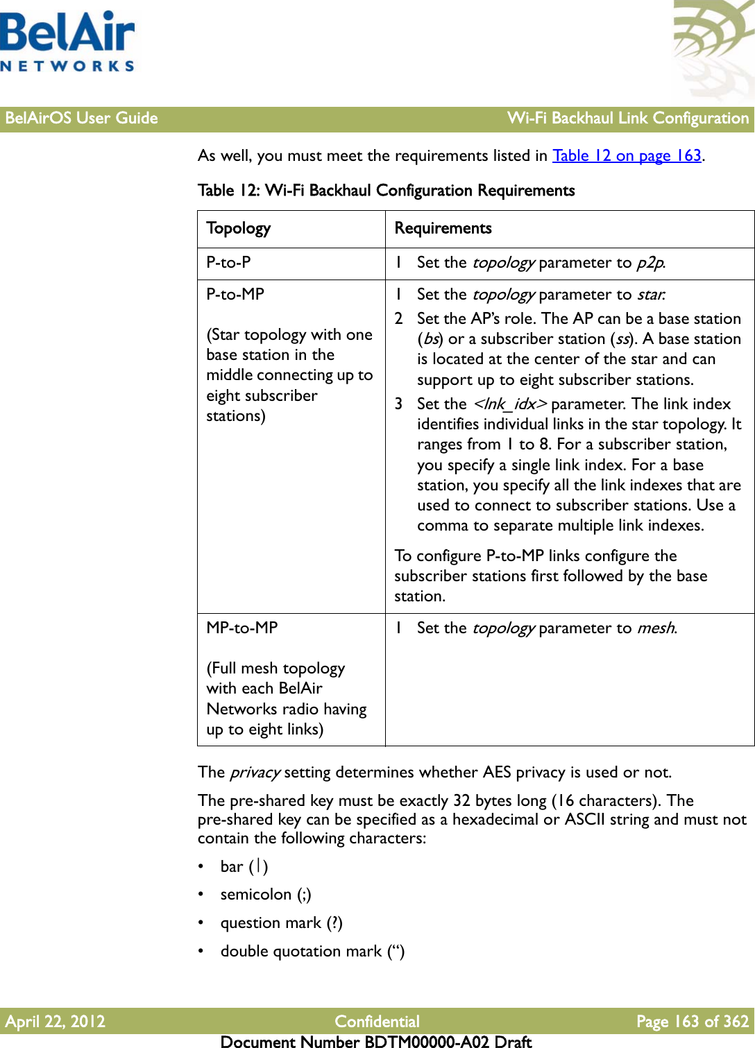
![BelAirOS User Guide Wi-Fi Backhaul Link ConfigurationApril 22, 2012 Confidential Page 164 of 362Document Number BDTM00000-A02 DraftManaging MP-to-MP MeshesThis section describe additional commands to help you configure and manage an MP-to-MP mesh clusters, including:•“Displaying the Mesh Topology” on page 164•“Setting a Link RSSI Threshold” on page 165•“Managing the Mesh Blacklist” on page 166•“Mesh Auto-connections” on page 166•“Managing Mesh Auto-connections” on page 167Displaying the Mesh To p o l o g y/interface/wifi-<n>-<m>/show backhaul statusThis command displays the operating parameters of the MP-to-MP links you are connected to. Example 1 and Example 2 that follow illustrate the output describing a mesh between three radios: RadioA, RadioB and RadioC.Example 1: RadioA/interface/wifi-4-1# show backhaul statusBackhaul Links: Link Radio MAC State(L,R) RSSI Radio Node IP Node Name ---- ----------------- ---------- ---- ----- -------- ---------- [S] 1 00:0d:67:0b:55:17 fwd fwd -49 wifi-3-1 180.1.5.120 [S] 2 00:0d:67:0b:51:ed fwd fwd -54 wifi-3-1 180.1.4.150 In the previous output, link 1 goes to RadioC and link 2 goes to RadioB. RadioA is measuring a signal strength of -49 dBm from RadioC. RadioC has a MAC address of 00:0d:67:0b:55:17 and is physical interface wifi-3-1 on an AP with IP address 180.1.5.120.RadioA is measuring a signal strength of -54 dBm from RadioB. RadioB has a MAC address of 00:0d:67:0b:51:ed and is physical interface wifi-3-1 on an AP with IP address 180.1.5.150.Example 2: RadioB/interface/wifi-3-1# show backhaul statusBackhaul Links: Link Radio MAC State(L,R) RSSI Radio Node IP Node Name ---- ----------------- ---------- ---- ----- -------- ---------- [S] 1 00:0d:67:0b:55:17 fwd fwd -68 wifi-3-1 180.1.5.120 [S] 2 00:0d:67:08:63:31 fwd fwd -54 wifi-4-1 180.1.5.180](https://usermanual.wiki/Ericsson-Wi-Fi/40005011.User-Manual/User-Guide-1698497-Page-164.png)
![BelAirOS User Guide Wi-Fi Backhaul Link ConfigurationApril 22, 2012 Confidential Page 165 of 362Document Number BDTM00000-A02 DraftIn the previous output, link 1 goes to RadioC and link 2 goes to RadioA. RadioB is measuring a signal strength of -68 dBm from RadioC. As in example 1, RadioC has a MAC address of 00:0d:67:0b:55:17 and is physical interface wifi-3-1 on an AP with IP address 180.1.5.120.As in example 1, RadioB is measuring a signal strength of -54 dBm from RadioA. RadioA has a MAC address of 00:0d:67:08:63:31 and is physical interface wifi-4-1 on an AP with IP address 180.1.5.180.Example 3: Mobile Backhaul Mesh/interface/wifi-1-1# show backhaul statusBackhaul Links: Link Radio Mac State(L,R) RSSI Radio Node IP Node Name ----- ----------------- ---------- ---- ----- -------- ---------- [M] 1 00:0d:67:09:23:6a fwd fwd -68 wifi-3-1 10.1.1.123 NYC_WALLST [M] 1 00:0d:67:00:08:06 fwd UP -71 wifi-3-1 10.1.1.122 NYC_BROADWAYIn the previous output, there are two mobile backhaul mesh links. One is forwarding while the other is listening.Setting a Link RSSI Threshold/interface/wifi-<n>-<m>/set backhaul mesh-min-rssi <rssi_value>This command lets you set a signal strength threshold for creating mesh links. If a radio signal from another AP is weaker than the specified threshold, then no link is created to that other AP, except if there is no other link to either AP at each end of the link. In that case, the link is still created even if the radio signal is weaker than the specified threshold.This command applies only when an AP is forming MP-to-MP links with other APs. Existing links are not affected by this command.The rssi_value parameter is specified in as a negative number in dBm. The default value is -100 dBm. Use the show config backhaul command to display the current value.Example/interface/wifi-1-1# set backhaul mesh-min-rssi -70The previous command sets the link RSSI threshold to -70 dBm. If the signal from another radio is stronger than -70 dBm, then a backhaul link to that radio is created. If it is weaker than -70 dBm, then a link is not created.](https://usermanual.wiki/Ericsson-Wi-Fi/40005011.User-Manual/User-Guide-1698497-Page-165.png)
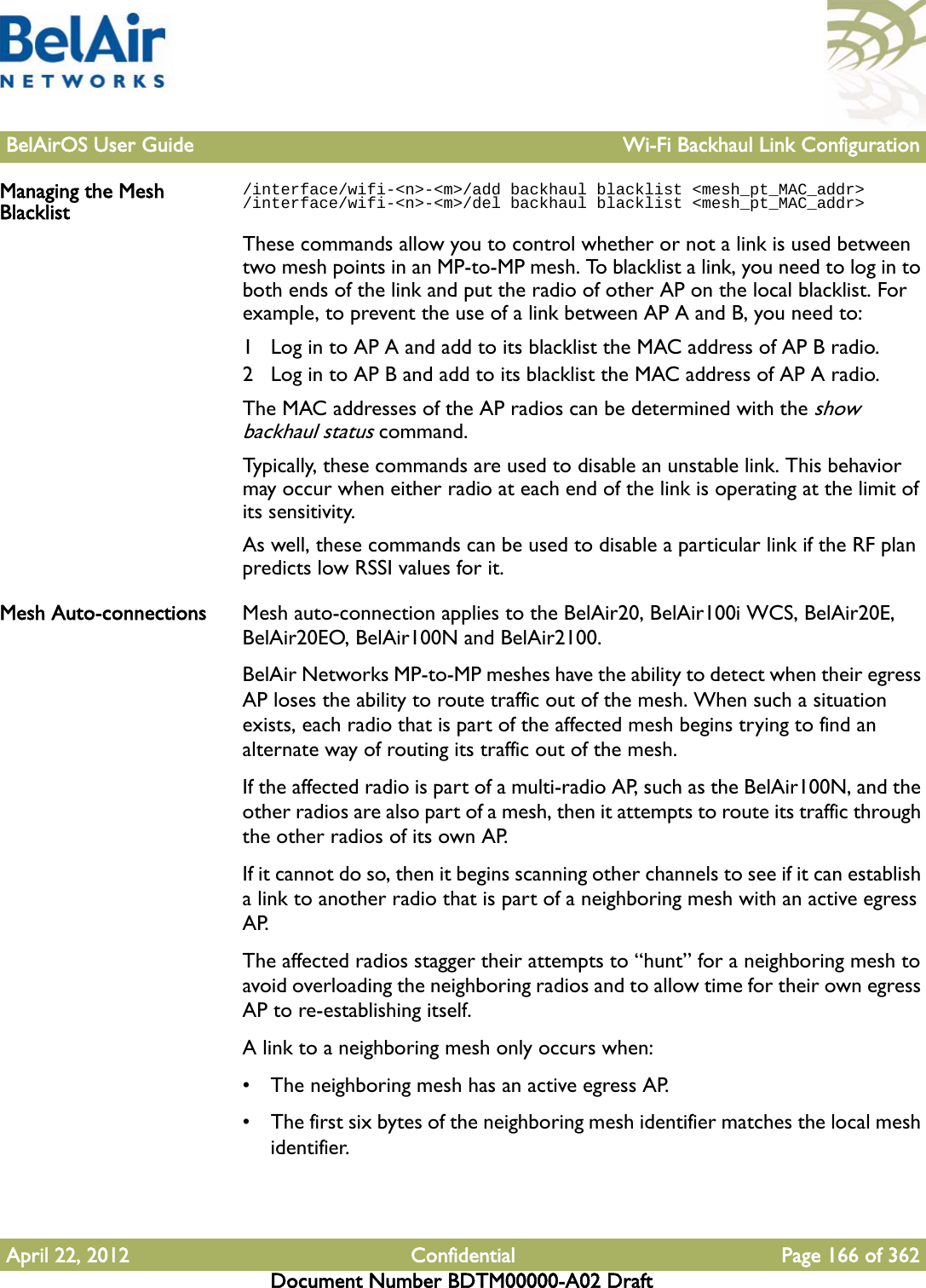
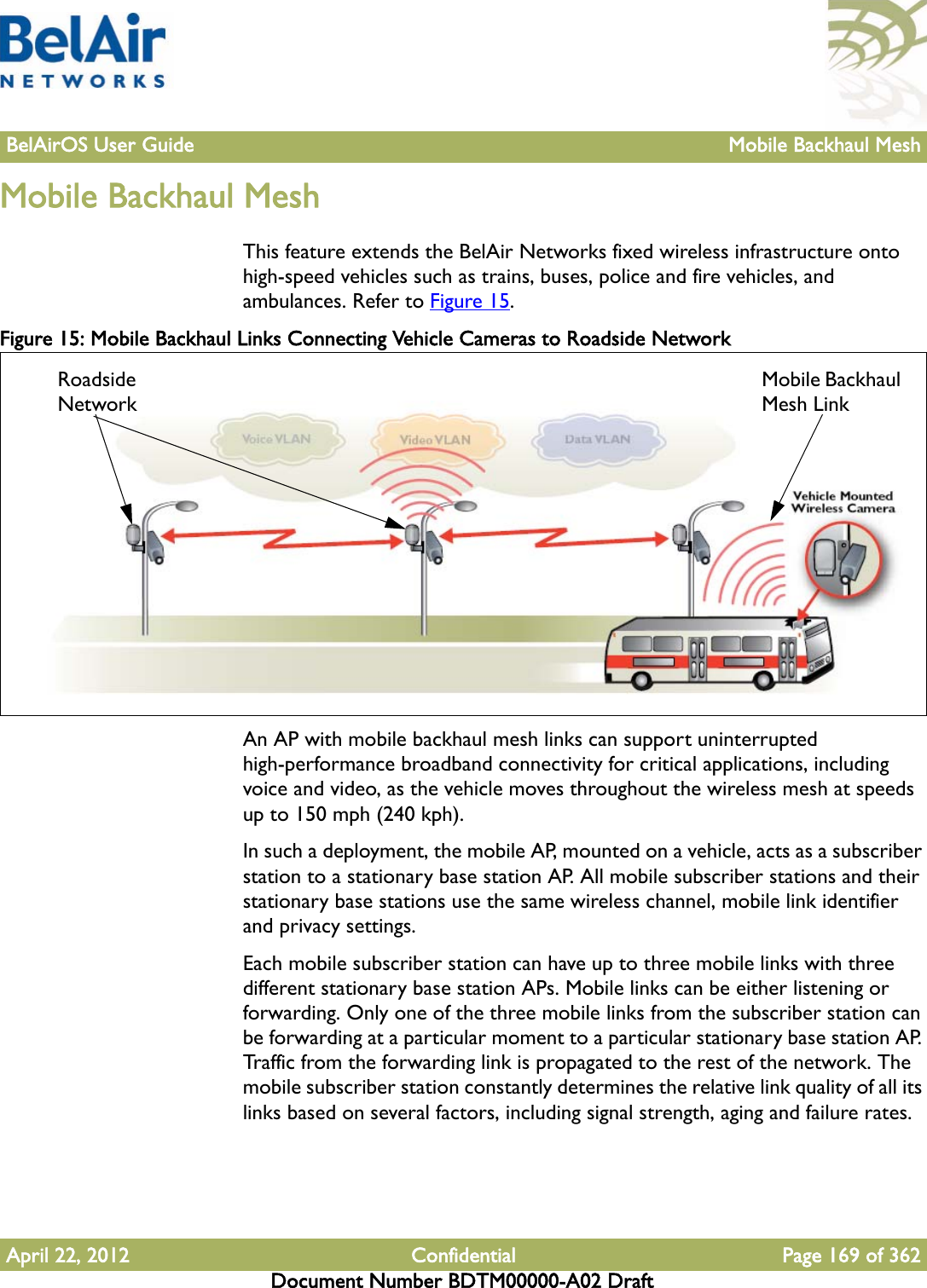
![BelAirOS User Guide Mobile Backhaul MeshApril 22, 2012 Confidential Page 170 of 362Document Number BDTM00000-A02 DraftWhen the mobile subscriber station determines that a listening link has a better link quality than the current forwarding link, it changes the link state so that the listening link with the higher quality becomes forwarding.These look ahead and make before break handover schemes allow the AP with mobile backhaul mesh links to provide uninterrupted support for a wide variety of applications, including voice and video.Each base station AP can support up to eight links. These can be mobile links or links to other stationary base stations. Mobile links can be either forwarding or listening. If a mobile subscriber station arrives within range of the base station, its forwarding link has precedence over the listening links of the other mobile subscriber stations.Configuring Mobile Backhaul Mesh LinksThe following tasks can be done:•“Displaying Mobility Configuration and Status” on page 170•“Configuring MIMO Operation for Mobile Applications” on page 171•“Configuring and Enabling Mobile Backhaul Mesh Links” on page 171Displaying Mobility Configuration and Status/interface/wifi-<n>-<m>/show backhaul mobility-path-select-historyThis command displays the history of a radio’s mobile path switches for debugging purposes. The displayed information includes an event ID, local RSSI, peer RSSI, failure rate, age time, mobile credit score, peer MAC, peer IP address, and the peer system name. Each radio stores up to 500 entries. The data is not persistent.Example/# interface/wifi-1-1/show backhaul mobility-path-select-history1 1970-01-01 10:46:30 new [-64 -58 0 0 -64 00:0d:67:09:7d:fa 10.1.1.110 BA100T_110]2 1970-01-01 11:54:44 chg [-57 -63 0 0 -63 00:0d:67:0c:6e:f4 10.1.1.120 BA100tt_120]3 1970-01-01 12:01:14 chg [-54 -57 0 0 -57 00:0d:67:09:7d:fa 10.1.1.110 BA100T_110]4 1970-01-01 12:22:30 chg [-55 -63 0 0 -63 00:0d:67:0c:6e:f4 10.1.1.120 BA100tt_120]5 1970-01-01 12:33:13 chg [-53 -53 0 0 -53 00:0d:67:09:7d:fa 10.1.1.110 BA100T_110]Additional Configuration Display CommandsRefer to the following sections and command descriptions:•“Displaying Backhaul Link Configuration” on page 161•“Displaying the Mesh Topology” on page 164•show rf-survey backhaul, described in “Backhaul RF Survey” on page 115](https://usermanual.wiki/Ericsson-Wi-Fi/40005011.User-Manual/User-Guide-1698497-Page-170.png)
![BelAirOS User Guide Mobile Backhaul MeshApril 22, 2012 Confidential Page 171 of 362Document Number BDTM00000-A02 DraftConfiguring MIMO Operation for Mobile Applications/interface/wifi-<n>-<m>/set mimo-mode {1x1|1x2|2x2|2x3|3x3}This command configures the Multiple-Input and Multiple-Output (MIMO) antenna settings for mobility applications using 802.11n radios, such as those for the BelAir20M. In such applications. the 5.8 GHz radio must operate with a MIMO setting of 1x1 while the 2.4 GHz access radio must operate with a MIMO setting of 2x2. Use this command to adjust the MIMO setting of each radio interface as required. The supported modes vary depending on the type of radios in your AP, as follows:• HTM and DRUE radios support only 1x1, 2x2 and 3x3 modes• HTME radios support only 1x1 and 2x2 modes• DRU radios support only 1x1, 1x2, 2x2 and 2x3 modesExample/interface/wifi-1-1# set mimo-mode 1x1/interface/wifi-1-2# set mimo-mode 2x2The previous commands apply to a BelAir20M where interface wifi-1-1 is for a 5.8 GHz radio while interface wifi-1-2 is for a 2.4 GHz access radio.Configuring and Enabling Mobile Backhaul Mesh Links/interface/wifi-<n>-<m>/set backhaul mobile ([identifier <link-id>] [role {bs|ss}] [privacy {{enabled key <pre_shared_key>}|disabled}] [admin-state {enable|disable}])This command configures the mobile backhaul link identifier, the role of the AP and backhaul privacy. It also lets you enable or disable mobile backhaul mesh functionality. The default setting is disable.The mobile backhaul link identifier identifies all members of a particular mobile backhaul mesh. The <link_id> parameter is case sensitive and can be up to 32 alphanumeric characters. A suitable link identifier is short phrase unique to the mobile backhaul mesh.When configuring a particular mobile backhaul mesh, you must configure all members to have:• the same channel. Refer to “Operating Channel” on page 105 for the appropriate command• the same mobile link identifier• the same privacy settings](https://usermanual.wiki/Ericsson-Wi-Fi/40005011.User-Manual/User-Guide-1698497-Page-171.png)
![BelAirOS User Guide Mobile Backhaul Point-to-point LinksApril 22, 2012 Confidential Page 175 of 362Document Number BDTM00000-A02 Draftd Set release 7 compatibility to yes if this AP is connecting to a shore AP running Release 7.1.0 software./services/mobility# set release-7-compatibility noe Optionally set the RSSI threshold.The minimum parameter specifies the minimum signal strength required to connect. The switch parameter defines the signal strength level at which a link switch occurs, provided the secondary link is better by at least the specified margin set and has an signal strength better than secondary.If the secondary link falls below the secondary threshold, the subscriber station begins scanning with its third or fourth radio if they exist./services/mobility# set RSSI minimum -85 margin 5 switch -70 secondary -75f Enable scanning by connecting the Wi-Fi interfaces to the appropriate scan-list./services/mobility# connect scan-list 1 wifi-2-14 Display the configuration and correct any settings as required. Use following commands as required.a Display the mobility configuration./services/mobility# show configTopology : point-to-pointRole : SSRel 7 : FalseNetwork Id : mobilityTestHome Check : Disable Link Id: AutoconfSSIDRSSI : minimum margin switch secondary---------- : ------- ------ ------ ---------(dbm) : -85 5 -70 -75b Display the scan lists./services/mobility# show scan-list 2Scan list [2] channels: 61 148 151Scan list [2] used by: wifi-2-1 (5GHz 802.11a) wifi-3-1 (5GHz 802.11a)c Display the links detected by scanning./services/mobility# show available-infra](https://usermanual.wiki/Ericsson-Wi-Fi/40005011.User-Manual/User-Guide-1698497-Page-175.png)
![BelAirOS User Guide Mobile Backhaul Point-to-point LinksApril 22, 2012 Confidential Page 177 of 362Document Number BDTM00000-A02 Draftb Add links needed to support service/services/mobility# add interface wifi-3-1Note: The scan-list, release-7-compatibility and RSSI thresholds parameters and apply only to subscriber stations. The show available-infra command applies only to subscriber stations.4 Display the configuration and correct any settings as required. Use following commands as required.a Display the mobility configuration./services/mobility# show configTopology : point-to-pointRole : BSRel 7 : FalseNetwork Id : .....BS OOS broadcast : EnabledBS OOS timeout : 180 (s)Home Check : Disable Link Id: AutoconfSSIDRSSI : minimum margin switch secondary---------- : ------- ------ ------ ---------(dbm) : -85 5 -70 -75b Display the interface list./services/mobility# show interface-listMobility BS Interfaces: wifi-2-1 wifi-3-1c Display the backhaul status./interface/wifi-2-1# show backhaul statusBackhaul Links: Link Radio Mac State(L,R) RSSI Radio Node IP Node Name ----- ----------------- ---------- ---- ----- -------- ---------- [S] 1 00:0d:67:09:c4:79 up fwd -59 wifi-2-1 10.1.1.208 ba200-ShoreAd Perform a backhaul survey./interface/wifi-2-1# show rf-survey backhaulmac addr ch RSSI age priv topo role linkIdx identifier (dbm) (s) 12345678----------------- --- ---- --- ---- ------ ---- -------- ----------00:0D:67:00:44:49 151 -27 0 none P-to-P -- -------- mobilityTestnoise floor: ................. -96 (dbm)](https://usermanual.wiki/Ericsson-Wi-Fi/40005011.User-Manual/User-Guide-1698497-Page-177.png)
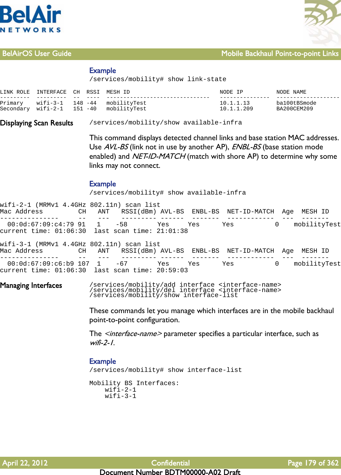
![BelAirOS User Guide Mobile Backhaul Point-to-point LinksApril 22, 2012 Confidential Page 180 of 362Document Number BDTM00000-A02 DraftManaging the Scan List /services/mobility/add scan-list <1-8> <chan_nums>/services/mobility/add scan-list <1-8> <chan_nums>/services/mobility/show scan-list {<1-8>|all}These commands let you manage the contents of up to eight scan lists.Example/services/mobility# show scan-list 2Scan list [2] channels: 61 148 151Scan list [2] used by: wifi-2-1 (5GHz 802.11a) wifi-3-1 (5GHz 802.11a)Associating a Scan List to an Interface/services/mobility/connect scan-list <1-8> <interface-name>/services/mobility/disconnect scan-list <1-8> <interface-name>These commands let you manage which interface uses which scan list.The <interface-name> parameter specifies a particular interface, such as wifi-2-1.Configuring RSSI Threshold/services/mobility/set rssi [minimum <-100 - 0>] [margin <5 - 20>] [switch <-100 - 0>] [secondary <-100 - 0>]This command lets you configure the RSSI parameters that the AP uses to determine the viability of creating primary and secondary links.The minimum parameter specifies the minimum signal strength required to connect. The switch parameter defines the signal strength level at which a link switch occurs, provided the secondary link is better by at least the specified margin set and has an signal strength better than secondary.If the secondary link falls below the secondary threshold, the subscriber station begins scanning with its third or fourth radio if they exist.Example/services/mobility# set RSSI minimum -85 margin 5 switch -70 secondary -75](https://usermanual.wiki/Ericsson-Wi-Fi/40005011.User-Manual/User-Guide-1698497-Page-180.png)
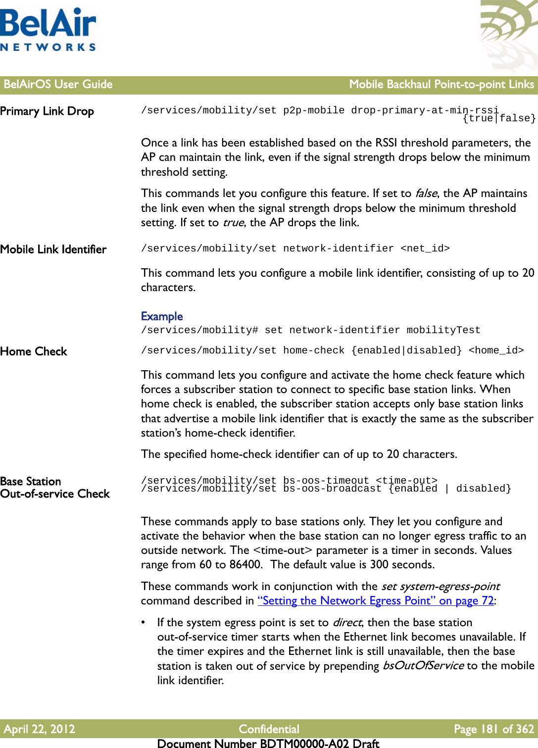
![BelAirOS User Guide Mobile Backhaul Point-to-point LinksApril 22, 2012 Confidential Page 182 of 362Document Number BDTM00000-A02 Draft• If the system egress point is set to indirect with a gateway IP address, then the base station pings the gateway IP address and starts the out-of-service timer if it does not receive a reply. If the timer expires and the gateway still does not reply, then the base station is taken out of service by prepending bsOutOfService to the mobile link identifier.Release 7 Compatibility /services/mobility/set release-7-compatibility {true|false}This command lets you connect a subscriber station to a base station running Release 7.1.0 software.Single Channel Mesh /services/mobility/set single-channel-mesh ([channel <chan_no>] [link-id <link_id>] [privacy {{enabled key <random_str>}|disabled}] [allow-multi-links {yes|no}])Normally, APs create a wireless mesh between themselves using multiple radio channels to avoid radio interference. However, in some mobile applications, in may be desirable to have all radios use a single channel. Such an application requires that all radios use directional antennas and are correctly positioned to avoid radio interference.This command allows you to configure such an application, where all radios use a single channel. This command must be invoked on each AP in the mesh.The <chan_no> parameter allows you to specify which channel to use.The <link_id> parameter is case sensitive and can be up to 32 alphanumeric characters. BelAir Networks recommends that the link identifier describes the link; that is, the APs it connects.The privacy setting determines whether AES privacy is used or not. The pre-shared key must be exactly 32 bytes long (16 characters). The pre-shared key can be specified as a hexadecimal or ASCII string and must not contain the following characters: •bar (|)•semicolon (;)• question mark (?)• double quotation mark (“)The allow-multi-link setting determines whether both a primary and secondary links are created between each AP in the mesh or just a primary. Multiple links increase redundancy, but in a single channel mesh application may limit the number of inter-connected APs. The default is no.](https://usermanual.wiki/Ericsson-Wi-Fi/40005011.User-Manual/User-Guide-1698497-Page-182.png)
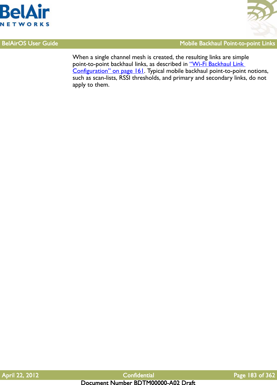
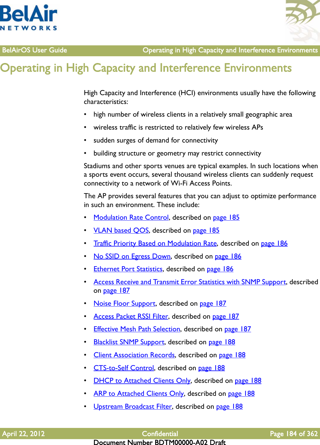
![BelAirOS User Guide Operating in High Capacity and Interference EnvironmentsApril 22, 2012 Confidential Page 186 of 362Document Number BDTM00000-A02 DraftTra ffic Pr io ri t y Based on Modulation RateA Wi-Fi AP sorts traffic according to priority and transmits it by priority in order of arrival. Different QOS schedulers (EDCA, LSPQ, SPQ) result in different performance for the various priorities. This feature applies a priority based on modulation rate on top of the QOS priority. It tries to give clients equal amounts of air-time instead of equal numbers of packets. The result in HCI environments is that more packets are sent to clients who are using higher modulation rates, increasing the effective bandwidth.For details, see “Rate Aware Fairness” on page 112. No SSID on Egress DownWhen this feature is enabled, all SSIDs on a radio can be modified with a text string, such as outOfService, when an AP loses its egress connection. In HCI environments, this feature prevents traffic from being uselessly directed to an AP which can not successfully forward it.This feature can be enabled or disabled on per radio basis. The text string can be configured on a per-SSID basis.The relevant commands are:•/interface/wifi-<n>-<m>/set ap-oos-broadcast {enabled|disabled} [option {replace|prepend}] and /interface/wifi-<n>-<m>/set ssid <ssid-number> ap-oos-identifier <oos_string> described in detail in “Out-of-service Advertising” on page 140.•/system/set system-egress-point {yes {direct|indirect gateway-ip <ip_addr>}|no} described in detail in “Setting the Network Egress Point” on page 72.Ethernet Port StatisticsEthernet port statistics are available for the BelAir200, BelAir100, BelAir100C and BelAir100T. In HCI environments, these statistics measure the traffic passing through the AP if its Ethernet port is connected to an external network.The relevant command is /interface/eth-1-1/show statistics, described in detail in the Troubleshooting Guide. The output includes:• received octets, unicast packets, multicast packets, broadcast packets and discarded packets• transmitted octets, unicast packets, multicast packets and broadcast packets](https://usermanual.wiki/Ericsson-Wi-Fi/40005011.User-Manual/User-Guide-1698497-Page-186.png)
![BelAirOS User Guide Operating in High Capacity and Interference EnvironmentsApril 22, 2012 Confidential Page 190 of 362Document Number BDTM00000-A02 DraftClient Authentication HistoryThis feature lets the operator display the details of the association and authentication process of the clients connected to the AP. In HCI environments, it can be used to troubleshoot client issues and determine how much success clients are having when attempting to access and use the network.The relevant command is /interface/wifi-<m>-<n>/show authentication history [mac <mac-address>], described in detail in the Troubleshooting Guide. Automatic Mesh ConnectThis feature allows APs to automatically reconnect to a network if they lose their egress connection. A cluster of meshed APs may lose their egress connection if the ethernet connection to the exterior network fails or if an AP fails. In this case, a member of the cluster looks for an alternate mesh to join and reconnect the isolated cluster.In HCI environments, this feature can be used for rapid deployment of a network. The APs in a network can be grouped by shared backhaul link identifier into a cluster. Multiple clusters can be deployed to control traffic flows and optimize backhaul performance.As soon as one AP in each cluster has an egress path, the whole cluster has egress. In the event that an egress fails, a cluster can self-repair by reconnecting to one of the other mesh clusters.Tr a f f i c Te s t To o l This tool provides an internal mechanism to measure the available traffic capacity of the network. The tool reports the throughput on a hop-by-hop basis from the AP under test to the destination IP address (another AP in the network).In HCI environments, this tool can be used to test the network deployment during the commissioning phase. It can be used to determine the theoretical capacity of the network and identify poorly performing links.The relevant command is:/diagnostics/test link IP <end point IP address> rate <traffic rate> [update_interval <report interval>] [duration <test duration>] [dir {tx|rx|both}]The command is described in detail in the Troubleshooting Guide.](https://usermanual.wiki/Ericsson-Wi-Fi/40005011.User-Manual/User-Guide-1698497-Page-190.png)
![BelAirOS User Guide DHCP Relay SettingsApril 22, 2012 Confidential Page 191 of 362Document Number BDTM00000-A02 DraftDHCP Relay SettingsThis chapter describes how to configure your AP’s DHCP Relay agent settings. You can configure up to five profiles for the DHCP Relay agent on your AP. Each profile specifies a subnet interface, which can be either the AP’s system interface or a VLAN. The DHCP server assigns an IP address to the client according to the subnet of this interface.Each profile also contains the IP addresses for up to three DHCP servers. When a profile is activated, the DHCP agent forwards a DHCP request to all the listed servers. The DHCP client receives packets from the first server to respond to the request.Profiles offer an easy way of configuring different DHCP servers for each subnet interface.Your AP can also add BelAir Networks specific information to the DHCP packets sent to the wireless client.Finally, you can create a list of valid IP address subnets to filter out unwanted directed and broadcast DHCP packets from your wireless network.The following topics are covered in this chapter:•“Displaying the DHCP Relay Configuration” on page 191•“Modifying DHCP Relay Parameters” on page 192•“Interface Administrative State” on page 193•“Assigning SSID Traffic to Use DHCP Relay” on page 193•“DHCP Address Filtering” on page 193•“DHCP Relay Performance Monitoring Statistics” on page 194See also “Providing Vendor Specific Information” on page 137.Displaying the DHCP Relay Configuration/protocol/dhcp/show config [{relay {all|<relay-idx>}} | {dhcp-allowed-subnet {all|<index 1-32>}}]The show config command displays DHCP Relay configuration:•Use show config to display information for all DHCP Relay profiles and all configured DHCP allowed subnet entries.](https://usermanual.wiki/Ericsson-Wi-Fi/40005011.User-Manual/User-Guide-1698497-Page-191.png)
![BelAirOS User Guide DHCP Relay SettingsApril 22, 2012 Confidential Page 192 of 362Document Number BDTM00000-A02 Draft•Use show config relay all to display information for all DHCP Relay profiles only.•Use show config relay <relay-idx> to display information on the specified DHCP Relay profile.•Use show config dhcp-allowed-subnet all to display all configured DHCP allowed subnet entries.•Use show config dhcp-allowed-subnet <index 1-32> to display information on the specified DHCP allowed subnet entry.Example/protocol/dhcp# show configIdx En DHCP Relay Info-----------------------------------------------------1 * Server[1] IP: 10.1.1.88 Interface: System2 * Server[1] IP: 10.1.100.88 Interface: Vlan-1003 * Server[1] IP: 10.1.200.88 Interface: Vlan-2004 No server configured 5 No server configuredModifying DHCP Relay Parameters/protocol/dhcp/set relay <relay-idx> server-addr-1 <ip-addr> [server-addr-2 <ip-addr>] [server-addr-3 <ip-addr>] interface {system | vlan <vlan-id>}/protocol/dhcp/del relay <relay-idx> server <server-idx>The set relay command creates a DHCP Relay profile or modifies an existing one. It configures the IP addresses of the DHCP servers to which the Relay Agent needs to forward the packets from the client. You must specify at least one DHCP server IP address and the type of interface; either system or a VLAN. The VLAN must be a valid VLAN management interface.The vlan_id parameter specifies that traffic be directed to the specified Virtual LAN (VLAN). The VLAN ID is an integer from 1 to 3015 and from 3018 to 4045. The del relay command removes only one IP address from each profile. To completely clear a profile, you must use the del relay command up to three times.Before clearing the profile, you must first make sure that no SSID is using that profile.](https://usermanual.wiki/Ericsson-Wi-Fi/40005011.User-Manual/User-Guide-1698497-Page-192.png)
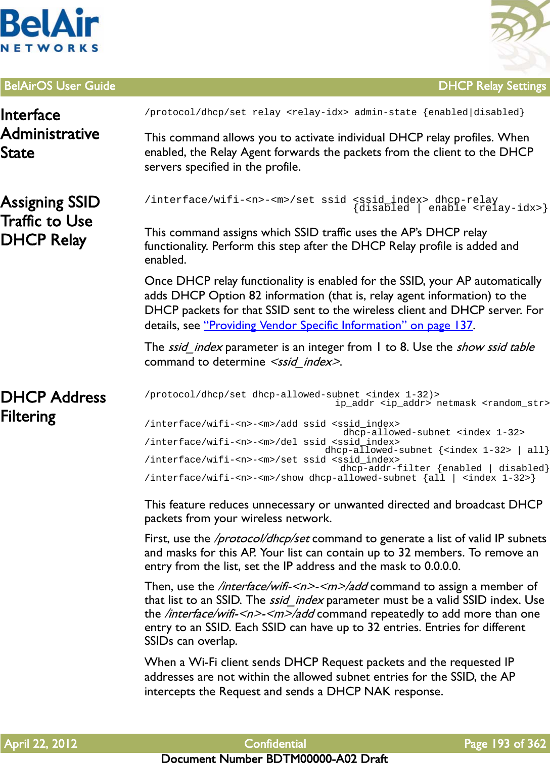
![BelAirOS User Guide DHCP Relay SettingsApril 22, 2012 Confidential Page 194 of 362Document Number BDTM00000-A02 DraftUse the equivalent /interface/wifi-<n>-<m>/del command to remove a subnet entry from an SSID. The /interface/wifi-<n>-<m>/set command allows you to enable or disable DHCP address filtering on individual SSIDs.Use the /interface/wifi-<n>-<m>/show ssid (ssid_index> config command to display whether DHCP address filtering is enabled for the SSID and the allowed subnets for the SSID.DHCP Relay Performance Monitoring Statistics/protocol/dhcp/show relay {aggregate|<relay-idx>} pm {fifteen-min|day} [{<0-96>|<0-7>|all}]This command displays DHCP Relay performance measurements for either a specific subnet interface as specified by the DHCP Relay profile index, or for an aggregate of all the subnet interfaces. The relay profile index ranges from one to five. For details on DHCP Relay settings, refer to “DHCP Relay Settings” on page 191.The displayed performance measurements are either for a specific time interval or for a series of time intervals. The valid parameter options are:•fifteen-min, fifteen-min 0 to fifteen-min 96•day, day 0 to day 7•all, all performance measurements. Specifying fifteen-min is equivalent to specifying fifteen-min 0 and means the current 15-minute interval. Specifying day is equivalent to specifying day 0 and means the current day, excluding data from the current 15-minute period.When aggregate is specified, the output displays the total number of dropped DHCP Relay packets for all subnet interfaces. When a specific relay profile index is specified, the output displays the number of DHCP packets that are relayed, both received and sent. Example 1/protocol/dhcp# show relay 1 pm fifteen-min 0 DHCP relay 1 message PMs: Interval type: current 15 minute Interval number: 0 DHCP relay messages received:BOOTREQUEST: 3DHCP Decline: 0DHCP Discover: 0DHCP Inform: 0DHCP Release: 3DHCP Request: 0](https://usermanual.wiki/Ericsson-Wi-Fi/40005011.User-Manual/User-Guide-1698497-Page-194.png)
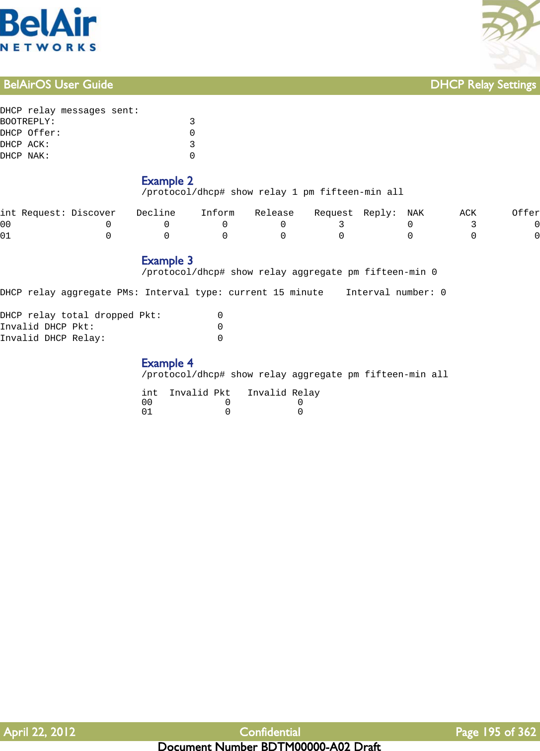
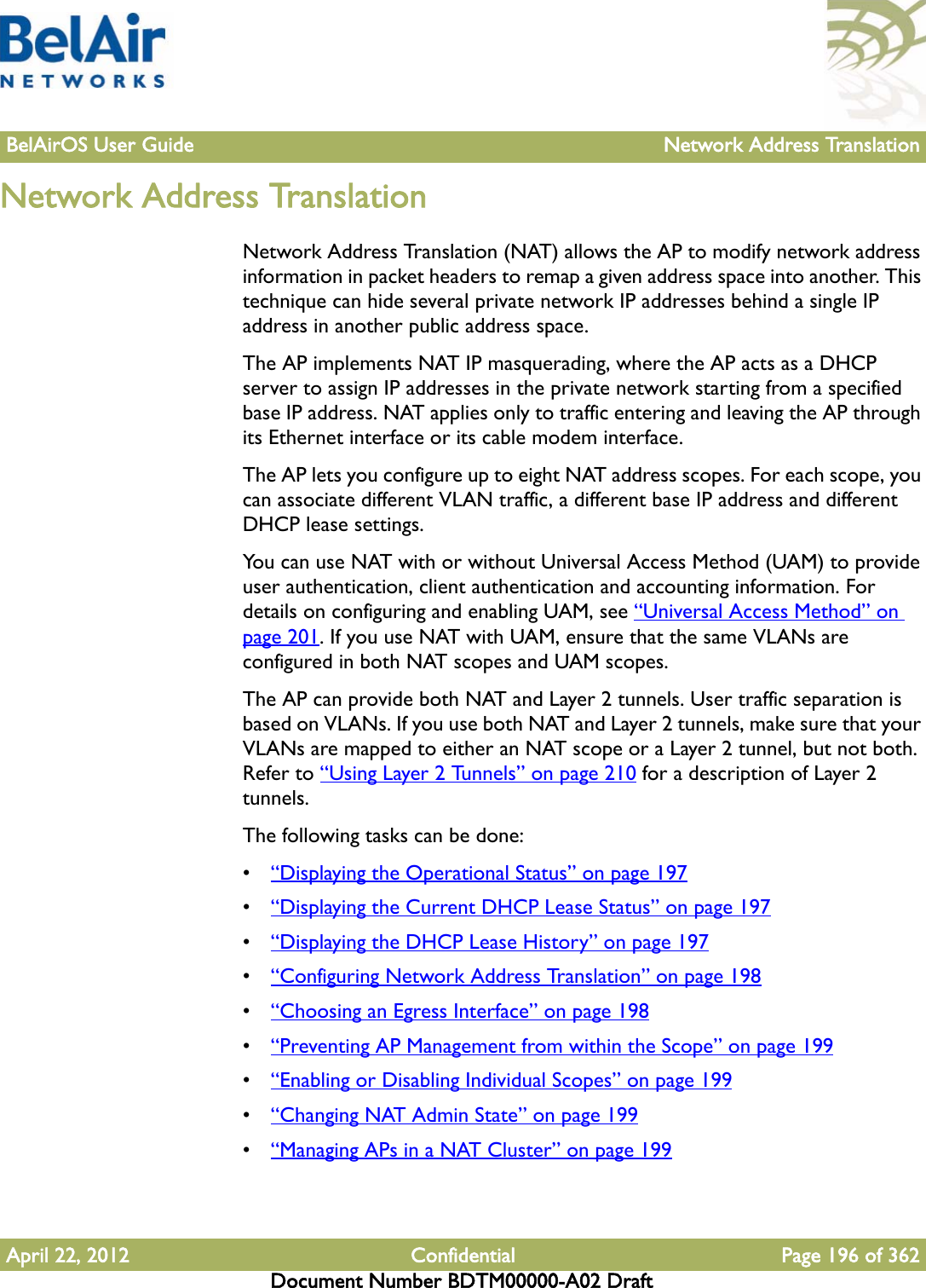
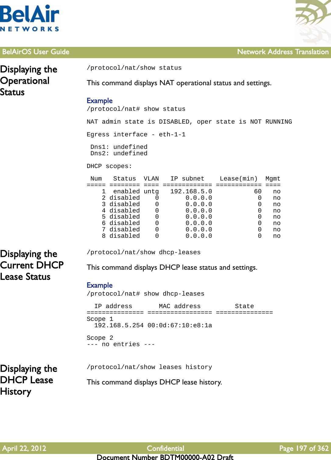
![BelAirOS User Guide Network Address TranslationApril 22, 2012 Confidential Page 198 of 362Document Number BDTM00000-A02 DraftExample/protocol/nat# show leases history IP address MAC address Lease & State=============== ================= ================================== 192.168.5.254 00:0d:67:10:e8:1a starts 2 2009/08/04 12:04:24 - State active 192.168.5.254 00:0d:67:10:e8:1a starts 2 2009/08/04 12:34:24 - State activeConfiguring Network Address Translation/protocol/nat/set scope <index (1-8)> dhcp-server {untagged | vlan <vlan_id>} based-ip <IP_addr> lease-time <minutes> [num-entries <number>]This command lets you configure the NAT settings for each address scope.The dhcp-server setting lets you specify which VLAN traffic to associate to the scope. The untagged setting specifies that the scope applies only to untagged traffic. The vlan <VLAN ID> settings specifies that the scope applies only to traffic with that VLAN ID. VLAN IDs cannot be shared across different scopes. The default setting is untagged. Refer to “Layer 2 Network Configuration” on page 231 for more information on VLAN configuration. The based-ip setting lets you specify the base IP address for the scope. Use xx.xx.xx.0 as the format. Once specified, the AP IP address becomes xx.xx.xx.1 and it begins to allocate addressed from xx.xx.xx.2 to xx.xx.xx.254.The lease-time setting lets you specify the maximum DHCP lease time in minutes for IP addresses supplied by NAT. The default is 60 minutes. Other DHCP server settings are based on those specified in “Configuring Dynamic IP Addressing” on page 62.The optional num-entries setting lets you specify the maximum number of IP addresses that can be allocated to clients in this scope. Values range from 1 to 253. The default value is 253. By default, scope 1 is preconfigured for untagged VLAN traffic with a base IP address of 192.168.5.0.Choosing an Egress Interface/protocol/nat/set egress {eth-1-1|cm-9-1} This command applies to the BelAir100SN and BelAir100SNE. The BelAir100SN and BelAir100SNE have two interfaces that can act as an egress point for NAT: the ethernet interface and the cable modem interface. This command lets you define which interface to use.](https://usermanual.wiki/Ericsson-Wi-Fi/40005011.User-Manual/User-Guide-1698497-Page-198.png)
![BelAirOS User Guide Universal Access MethodApril 22, 2012 Confidential Page 203 of 362Document Number BDTM00000-A02 DraftDisplaying the Current Configuration/services/uam/show config [scope <index (1-8)>]This command displays the current UAM configuration. Specifying a scope displays just that scope. Note: This command displays only the host, mac and protocol white list entries that you control through the add and del commands. (See “Managing White List Entries” on page 206.) This commands does not display the white list entries that the AP automatically tracks internally.Example/services/uam# show config scope 2Scope 2 Configuration:----------------------admin state: .................... Enabledmac authentication state:........ Enabledmac authentication password:.....mac authentication success redirect:Enabledmac authentication reject suspend: Enabledaccounting state:................ Enabledauthentication web server url:... http://secure2.worldspot.net/wk/Uamauthentication shared secret:.... Mm94XVjzugsplash web server url:...........uam local interface:............. Systemwan-mode admin state: ........... Disabledwan-mode web server key:.........radius servers:.................. 2radius nasid:.................... BelAirHotspothost-white-list: www.paypal.com www.paypalobjects.com paypal.112.2o7.net www.belairnetworks.commac-white-list:protocol-white-list:vlan-list: 10added redirect variable pairs: ssid mySsid locationId myLocationDisplaying the Operational Status/services/uam/show status [scope <index (1-8)>]This command displays UAM operational status and settings.Example/services/uam# show status scope 2Scope 2 Status:](https://usermanual.wiki/Ericsson-Wi-Fi/40005011.User-Manual/User-Guide-1698497-Page-203.png)
![BelAirOS User Guide Universal Access MethodApril 22, 2012 Confidential Page 204 of 362Document Number BDTM00000-A02 Draft----------------------admin state: .................... Enabledmac authentication state:........ Enabledaccounting state:................ Enabledauthentication web server ip:.... secure2.worldspot.net resolved IP addresses: 69.64.50.37authentication shared secret:.... Mm94XVjzugsplash web server ip:............ resolved IP addresses:radius servers:.................. 2radius nasid:.................... BelAirHotspothost-white-list: www.paypal.com: resolved IP addresses: 66.211.169.2 66.211.169.65 64.4.241.33 64.4.241.49 www.paypalobjects.com: resolved IP addresses: 184.29.112.146 paypal.112.2o7.net: resolved IP addresses: 66.235.139.118 66.235.138.18 66.235.139.121 66.235.138.19 www.belairnetworks.com: resolved IP addresses: 206.191.51.223 optimumwifi.optimum.net: resolved IP addresses: 167.206.247.50mac-white-list:protocol-white-list:vlan-list: 10 800local info: uamPort:..................... 3991 radius-server-index:......... 2 radius-local-ip:............. 10.100.1.9 uam-local-ip:................ 10.100.1.9 uam-logout-ip:............... 1.1.1.1Displaying the Client Session Information/services/uam/show client-session [{ip <ip_str>|mac <mac_str>|scope <num_str>}]This command displays UAM client session information.Example/services/uam# show client-sessionClient-Session:](https://usermanual.wiki/Ericsson-Wi-Fi/40005011.User-Manual/User-Guide-1698497-Page-204.png)
![BelAirOS User Guide Universal Access MethodApril 22, 2012 Confidential Page 205 of 362Document Number BDTM00000-A02 Draft----------------------ip address: .................... 10.100.1.210Mac address: ................... 00:1E:E5:DE:DD:C5Scope: ......................... 1Vlan: .......................... untagAuthenticated: ................. yesUser Name: ..................... BAunlimRedirect url: ..................User url: ...................... http://fxfeeds.mozilla.com/en-US/firefox/headlines.xmlBandwidth MaxUp: ............... 0Bandwidth MaxDown: ............. 0Max Input Octets: .............. 0Max Output Octets: ............. 0Max Total Octets: .............. 0Timeout: ....................... 14526Idle Timeout: .................. 300Accounting interim Interval: ... 600Terminate Time: ................ 0Start Time: .................... 1280150841Last Active Time: .............. 1280150841Last Accounting Update Time: ... 1280150841Last Radius Request Time: ...... 1280150841Input Packets: ................. 0Output Packets: ................ 0Input Octets: .................. 0Output Octets: ................. 0Input Gigawords: ............... 0Output Gigawords: .............. 0Internal Usage Info:Radius Session Id: ............. 547999736Radius Uam Port: ............... 41Radius Act State: .............. 4Uam Challenge Start Time: ...... 1280150841Suspend Time: .................. 60Suspend Start Time: ............ 0Current Time: .................. 1280150905Specifying the Web Ser ver/services/uam/set scope <index (1-8)> auth-url <url-string> shared-secret <string> [splash-url <url-string>] [uam-interface {system | {vlan <vlan-str>}}]This command lets you specify the URL of the Web server for individual UAM scopes.The splash URL specifies a special usage web page (for example, advertisement). If it is configured, the AP redirects the user to the splash page instead of authentication page. The splash page then redirects the user to authentication server. The AP does not control the behavior of the splash page.If the splash-url parameter is not specified, then the user is sent directly to the authentication server.](https://usermanual.wiki/Ericsson-Wi-Fi/40005011.User-Manual/User-Guide-1698497-Page-205.png)
![BelAirOS User Guide Universal Access MethodApril 22, 2012 Confidential Page 207 of 362Document Number BDTM00000-A02 DraftHost entries can contain URLs or IP addresses. The host white list and the MAC address white list can have up to 10 entries. The protocol white list can be empty or contain ICMP only.In addition to the entries you control with these add and del commands, the AP has an internal white list that contains the DHCP, DNS and ARP protocols, and the URLs for the authentication server and the splash page (if specified).Example/services/uam# add scope 1 host-white-list www.mysite.comAssociating VLAN Traffic to a Scope/services/uam/add scope <index (1-8)> vlan {<vlan-list>|untagged}/services/uam/del scope <index (1-8)> vlan {<vlan-list>|untagged}These commands let you associate different VLAN traffic with different UAM scopes. If you specify untag, then untagged traffic is associated with the specified UAM scope.See “Configuring IP Parameters” on page 62 for a description on how to set up VLANs for dynamic and static IP addressing.Performing MAC Address Authentication/services/uam/set scope <index (1-8)> mac-auth-state {enabled|disabled} [passwd <string>] [success-redir {enabled|disabled}] [reject-suspend {enabled|disabled}]This command lets you control whether or not client MAC address authentication is performed when a client attempts to associate to the AP. When this feature is enabled, the AP determines the client’s MAC address when the client attempts to associate with AP. The AP then sends the MAC address to the RADIUS server for authentication. If the server authenticates the MAC address, then the user has full access to the Internet when the association completes. If the RADIUS server does not authenticate the MAC address, then the user must provide credentials through the typical UAM mechanism (Web server, RADIUS server, white lists) before they can access the Internet. The default setting is enabled.The passwd parameter provides an alternate password to log into the RADIUS server.](https://usermanual.wiki/Ericsson-Wi-Fi/40005011.User-Manual/User-Guide-1698497-Page-207.png)
![BelAirOS User Guide Universal Access MethodApril 22, 2012 Confidential Page 209 of 362Document Number BDTM00000-A02 DraftOperating in WAN Mode/services/uam/set scope <index (1-8)> wan-mode admin-state {enabled|disabled} [web-server-key <key-str>] UAM WAN mode is for special applications that use alternate communications between the AP, the Web server and the RADIUS authentication server. For additional details, contact your BelAir Networks representative.Changing UAM Admin State/services/uam/set scope <index (1-8)> admin-state {enabled|disabled}This command lets you enable or disable UAM functionality for individual UAM scopes. The default setting is disabled.](https://usermanual.wiki/Ericsson-Wi-Fi/40005011.User-Manual/User-Guide-1698497-Page-209.png)
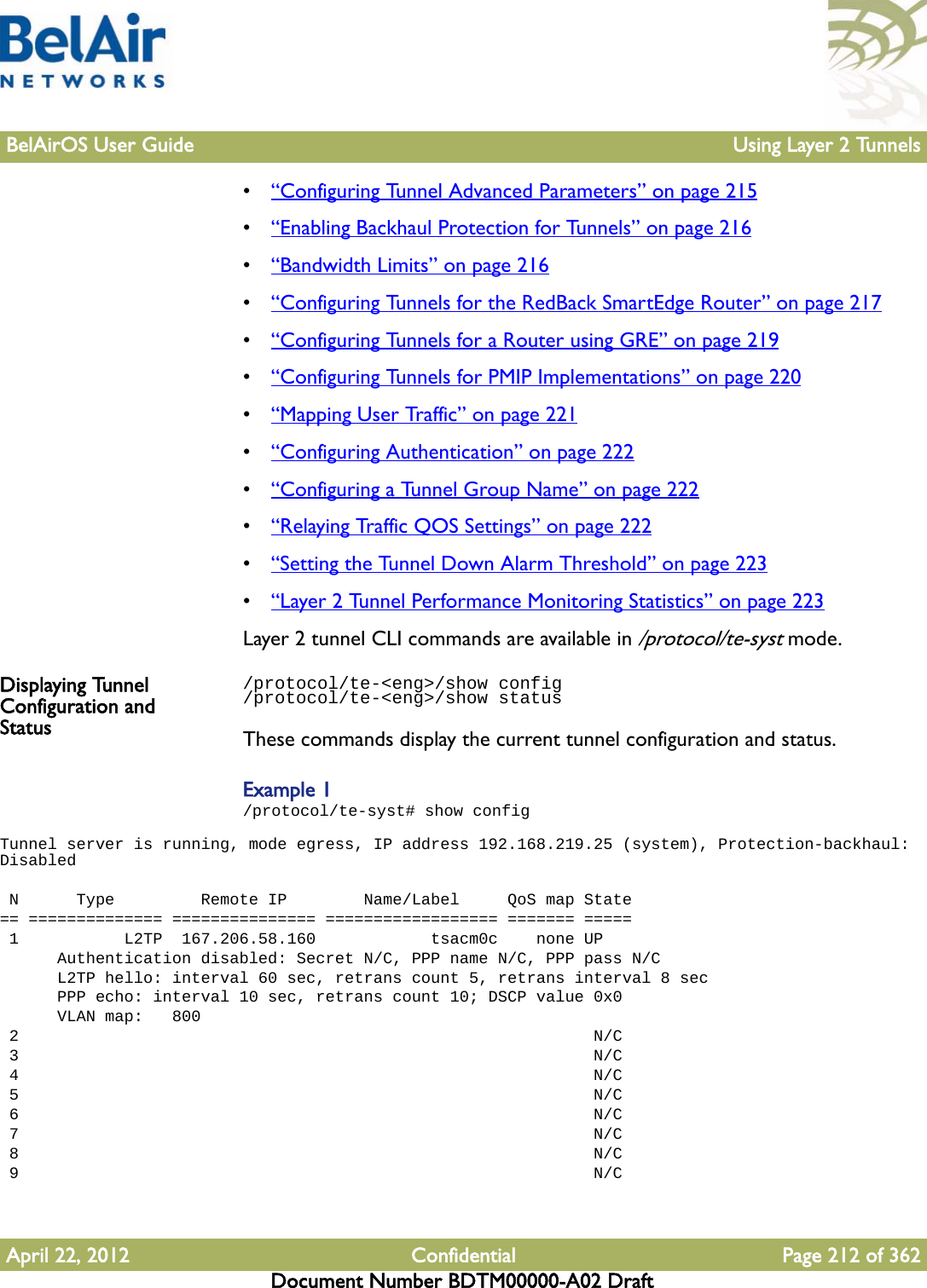
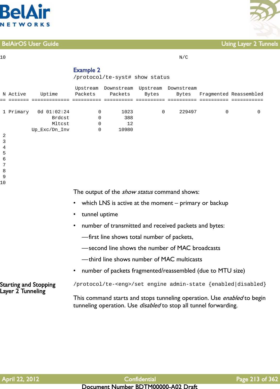
![BelAirOS User Guide Using Layer 2 TunnelsApril 22, 2012 Confidential Page 214 of 362Document Number BDTM00000-A02 DraftConfiguring Layer 2 Tunnels/protocol/te-<eng>/set tunnel <index> ip <peer_IP_addr> name <stn_name> [backup-ip <backup_IP_addr> [backup-name <backup_name>]] [switch {non-revertive | revertive}]/protocol/te-<eng>/delete tunnel {all|<index>}The set tunnel command creates a new tunnel to be terminated at the specified peer IP address, which is usually the network central router. You can create up to 10 tunnels to the same peer or to different peers. Each tunnel carries just one L2TP session.The <index> parameter is used for easy reference when using other commands. It can be displayed with the /protocol/te-<eng>/show config command. The <stn_name> parameter can be any series of 18 alphanumeric ASCII characters. L2TP protocol provides the <stn_name> parameter to the other end point so it can identify different tunnels coming from the same IP address or create logical group of APs with the same name and different IP addresses. You can optionally specify the IP address and name of a backup server. If a tunnel cannot be created to the main router or if a tunnel fails, the backup parameters become active. The switch parameter controls whether the use of a backup router is revertive or not. Once the AP starts to use a tunnel to a backup router:• If switch is set to non-revertive, then the AP uses the tunnel to the backup router until it fails. Only then does the AP switches back to the tunnel using the main router. This is the default setting.• If switch is set to revertive, then the AP uses the tunnel to the backup router only while the main tunnel is unavailable. The AP switches back to the tunnel using the main router as soon as it becomes available again.The delete tunnel command removes all tunnels or the specified tunnel. After using this command, user data mapped to this tunnel is dropped instead of forwarded.Setting Tunnel Engine Parameters/protocol/te-<eng>/set mode {local|egress} [interface-vlan <VLAN_ID>]The set mode command is used when the AP is connected to other APs through backhaul links. In this case, you may want the AP to act as an egress point and put access traffic from itself and the other APs into the tunnel. Use local mode when the AP puts only its own access traffic into the tunnel. Use](https://usermanual.wiki/Ericsson-Wi-Fi/40005011.User-Manual/User-Guide-1698497-Page-214.png)
![BelAirOS User Guide Using Layer 2 TunnelsApril 22, 2012 Confidential Page 215 of 362Document Number BDTM00000-A02 Draftegress mode when the AP puts its own access traffic and that of many other APs into the tunnel.If the VLAN interface is not specified, the AP’s management IP address is used to identify the local tunnel end point. IP addresses may be manually configured or obtained by DHCP. If a VLAN interface is specified, it must be previously configured. Refer to “Layer 2 Network Configuration” on page 231.Configuring Tunnel Advanced Parameters/protocol/te-<eng>/set tunnel <index> advanced [l2tp-hello-interval <seconds>] [l2tp-hello-retrans <number>] [l2tp-hello-timeout <seconds>] [ppp-echo-interval <seconds>] [ppp-echo-retrans <number>] [dscp-control <hex value>]The set tunnel advanced command lets you specify for particular tunnel timers and other parameters associated with the L2TP protocol.The <index> parameter is used for easy reference when using other commands. It can be displayed with the /protocol/te-<eng>/show config command. The following parameters can be set with this command:• L2TP Hello transmission interval. Values range from 10 to 300 seconds. The default setting is 60 seconds.• L2TP Hello retransmission count. Values range from 1 to 10. The default setting is 5.• L2TP Hello retransmission maximum interval. Values range from 1 second to 32 seconds. The default setting is 8 seconds.• PPP echo transmission interval. Values range from 0 seconds to 300 seconds. 0 seconds means PPP echo is disabled. The default setting is 10 seconds.• PPP echo retransmission count. Values range from 1 to 50. The default setting is 10.• DSCP value for control (L2TP/PPP) packets. The default setting is 0.The AP uses the L2TP Hello parameters to determine if the tunnel is available. If the AP does not receive a Hello packet during the L2TP Hello transmission interval, it begins to send its own Hello packets at exponential intervals starting at 1 second (that is, at 1, 2, 4, 8, ... seconds) until the L2TP Hello retransmission](https://usermanual.wiki/Ericsson-Wi-Fi/40005011.User-Manual/User-Guide-1698497-Page-215.png)
![BelAirOS User Guide Using Layer 2 TunnelsApril 22, 2012 Confidential Page 216 of 362Document Number BDTM00000-A02 Draftcount and L2TP Hello retransmission maximum interval are reached. If none of the retransmitted Hello packets are answered, then the tunnel is considered unavailable. For additional details, refer to the L2TP specification.The PPP echo parameters are also used to determine tunnel availability. PPP echo packets are sent periodically with the interval specified by the PPP echo transmission interval. The tunnel is considered unavailable if the AP does not receive consecutive responses for the number of packets specified by the PPP echo retransmission count.If you specify a DSCP value, then it appears in the DSCP/TOS bits of any L2TP or PPP control packets. Enabling Backhaul Protection for Tunnels/protocol/te-<eng>/set protection-backhaul {enabled|disabled} [egress <interface>]Use this command to inform the tunnel engine that the AP uses egress protection as described in “Egress Protection” on page 168. The egress parameter applies to BelAir100SN only. It species whether egress is through the cable modem (cm-9-1) or the Ethernet interface (eth-1-1). The default setting is disabled. Before using this command, make sure all requirements described in “Egress Protection” on page 168 are met.When you enable or disable backhaul protection for tunnels, you must:1 Issue the config-save command. See “Saving your Changes” on page 37 for details.2 Reboot the AP. See “Activating a Software Load” on page 250 for details.Bandwidth Limits /protocol/te-<eng>/show limits/protocol/te-<eng>/set tunnel <index> bandwidth-limit upstream <bits-per-second> downstream <bits-per-second>The set tunnel bandwidth-limit command lets you specify for a particular tunnel the maximum upstream and downstream transmission rates. The <index> parameter is used for easy reference when using other commands. It can be displayed with the /protocol/te-<eng>/show config command.The show limit command displays the upstream and downstream settings for the current tunnel.](https://usermanual.wiki/Ericsson-Wi-Fi/40005011.User-Manual/User-Guide-1698497-Page-216.png)
![BelAirOS User Guide Using Layer 2 TunnelsApril 22, 2012 Confidential Page 217 of 362Document Number BDTM00000-A02 DraftExample/protocol/te-syst# show limits N Us limit Ds limit== ========== ========== 1 0 0 2 3 4 5 6 7 8 910Configuring Tunnels for the RedBack SmartEdge Router/protocol/te-<eng>/set tunnel-l2vpn <index (1-10)> oam {enabled | disabled} {auto | ip <ip_addr> label <number> [backup-ip <ip_addr>] [backup-label <number>]} [switch {non-revertive | revertive}]/protocol/te-<eng>/set l2vpn autoconfig {ip <ip_addr> | hostname <host_name>} username <string> password <string> [retry-min <sec>] [retry-max <sec>] [wait-time <min>]/protocol/te-<eng>/l2vpn autoconfig renew/protocol/te-<eng>/set tunnel-l2vpn <index (1-10)> advanced inactivity-timer <seconds>These commands are used to create a tunnel to the central router using Ethernet-over-MPLS-over-GRE encapsulation instead of L2TP.Use the set tunnel-l2vpn command to create L2VPN tunnels to the specific destination. L2VPN tunnels may co-exist with regular L2TP tunnels and GRE tunnels on the same AP.The oam parameter defines if the tunnel uses a failure detection mechanism based on 802.1ag CCM packets. If oam is disabled, the AP considers the tunnel to always be up. If oam is enabled, the AP relies on receiving 802.1ag CCM packets to detect tunnel state. These packets should be generated by outside equipment in the head end and should be forwarded to all APs. Set oam to enabled if you are using backup.The auto parameter tells the AP that it should obtain L2VPN parameters (IP address and label) from the NetOp NSM server. This is a preferred setting for large deployments.The ip and backup-ip parameters specify IP addresses of the head end tunnel endpoint. It is usually the IP address of a SmartEdge device terminating L2VPN](https://usermanual.wiki/Ericsson-Wi-Fi/40005011.User-Manual/User-Guide-1698497-Page-217.png)
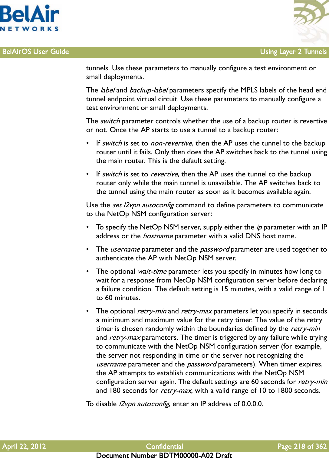
![BelAirOS User Guide Using Layer 2 TunnelsApril 22, 2012 Confidential Page 219 of 362Document Number BDTM00000-A02 DraftUse the l2vpn autoconfig renew command to trigger getting a new set of configuration parameters from the NetOp NSM configuration server.Use the set l2vpn advanced inactivity-timer command to specify how long to wait until declaring the L2VPN tunnel down. The <seconds> parameter ranges from 10 to 1000 seconds. The default value is 60 seconds.Configuring Tunnels for a Router using GRE/protocol/te-<eng>/set tunnel-gre <index (1-10)> ip <ip_addr> [proxy-arp {all | list | dhcp}]/protocol/te-<eng>/set tunnel-gre <index (1-10)> arp-list <IP_addr> [<IP_addr>] [<IP_addr>] [<IP_addr>] [<IP_addr>]/protocol/te-<eng>/set gre autoconfig ip <IP_addr> interval <seconds> [port <TCP_port>]These commands are used to create tunnel to the central router using IP-over-GRE encapsulation instead of L2TP.Use the set tunnel-gre ip command to create GRE tunnels to the specific destination. GRE tunnels may co-exist with regular L2TP tunnels and L2VPN tunnels on the same AP. The ip parameter specifies the IP address of the head end tunnel endpoint. It is usually the IP address of the router terminating GRE tunnels.This type of configuration uses proxy ARP because it cannot act as a router to terminate IP traffic. The proxy-arp parameter defines the scope of the proxy ARP functionality:•Use all if you want to answer ARP requests for any destination IP address.•Use dhcp if you want to answer ARP requests for the default gateway IP address only. In this case, the gateway IP address is learned from the DHCP relay communication to the client.•Use list to apply proxy ARP only to traffic destined to a particular set of IP address. Use the set tunnel-gre arp-list command to specify the set of IP addresses. The default value of the proxy-arp parameter is all.Use the set gre autoconfig command to define parameters to communicate to the third-party heartbeat server using a proprietary protocol. The ip parameter defines the IP address of heartbeat server. To disable this feature, configure the GRE heartbeat server with ad IP address of 0.0.0.0.In this configuration, the AP sends a pseudo heartbeat packet at the interval specified by the interval parameter. The <seconds> parameter should be at](https://usermanual.wiki/Ericsson-Wi-Fi/40005011.User-Manual/User-Guide-1698497-Page-219.png)
![BelAirOS User Guide Using Layer 2 TunnelsApril 22, 2012 Confidential Page 220 of 362Document Number BDTM00000-A02 Draftleast 60 seconds. The default value is 60 seconds. The heartbeat server uses the pseudo heartbeat packet to determine whether the tunnel’s operational state is up or down. The heartbeat server also uses the pseudo heartbeat packet to determine the AP’s tunnel configuration and corrects it if required.The optional port parameter specifies the TCP port to communicate with the heartbeat server. The default value is 4040.Configuring Tunnels for PMIP Implementations/protocol/te-<eng>/set tunnel-pmip <index (1-10)> ha-ip <ip_addr> secret <string> spi <number> [lease-time <seconds>]/protocol/te-<eng>/set tunnel-pmip <index (1-10)> advanced dns1 <ip_addr> [dns2 <ip_addr>]These commands are used to create a Proxy Mobile IPv4 (PMIP) tunnel. A PMIP tunnel allows a mobile client to change its point-of-attachment to the Internet without changing its IP address. In this implementation, the network tracks the movements of the mobile client and initiates the required mobility signalling on its behalf. In PMIP mode, the AP acts as MIP Foreign Agent.Use the set tunnel-pmip ha-ip command to create a tunnel to a PMIP home agent. PMIP tunnels may co-exist with regular L2TP tunnels and L2VPN tunnels on the same AP. The ha-ip parameter specifies the IP address of PMIP Home Agent (HA). The secret parameter specifies the authentication password for access to the PMIP HA. The spi parameter specifies the index identifying a security context between the AP and home agent. It is an integer value that should be greater than 255. The spi parameter and the secret parameter are used together to authenticate the AP with the HA.The optional lease-time parameter specifies the maximum lease-time in seconds for the client session. If the client does not send packets for more than the specified lease-time, its session is dropped. The default value is 300 seconds. When client traffic is forwarded through the PMIP tunnel, the AP acts as a DHCP server and provides all corresponding parameters (such as client's IP address, subnet mask, gateway, and DNS addresses). The AP proxies all these parameters from the HA. If the HA is unable to provide some of these](https://usermanual.wiki/Ericsson-Wi-Fi/40005011.User-Manual/User-Guide-1698497-Page-220.png)
![BelAirOS User Guide Using Layer 2 TunnelsApril 22, 2012 Confidential Page 221 of 362Document Number BDTM00000-A02 Draftparameters (it must provide at least the client's IP address), the following logic is used by the AP:• The subnet mask is determined as corresponding to the IP class by IP address. For example, for IP address 67.100.125.10 subnet mask is 255.0.0.0.• The gateway is taken as first address within a specified subnet. For the previous example, the gateway address is 67.0.0.1. This gateway address is provided by the AP itself and may not correspond to any real IP address in the network.• The DNS IP address(es) are determined by the set tunnel-pmip advanced dns command.Use the set tunnel-pmip advanced dns1 command to define the DNS server IP addresses to be provided to the client by the AP through DHCP in case the AP can not obtain corresponding settings from the HA. The optional dns2 parameter specifies the backup DNS server in case the primary one is unreachable.Mapping User Traffic /protocol/te-<eng>/map vlan {untagged|<VLAN ID>} to <index> [domain <string>]/protocol/te-<eng>/unmap vlan {all|untagged|<VLAN ID>}The map vlan command instructs the tunnel engine to forward traffic to the specified tunnel. You can specify either traffic associated with a specific VLAN or traffic that is not tagged for any VLAN. All packets that meet this criteria received by any of the AP’s radios are forwarded through the tunnel. If the tunnel is not configured or not active, all corresponding packets are dropped. If you specify untagged traffic, then the tunnel interface itself must be associated with a VLAN. Refer to “Setting Tunnel Engine Parameters” on page 214.The optional domain parameter is for PMIP tunnels. Some PMIP implementations require an additional identification string to communicate with the PMIP Home Agent (HA). The domain parameter allows you to specify the required string.The unmap vlan command removes all tunnel mapping entries or a specified tunnel mapping entry. After this command, the specified packets are then forwarded as if the tunnel does not exist.](https://usermanual.wiki/Ericsson-Wi-Fi/40005011.User-Manual/User-Guide-1698497-Page-221.png)
![BelAirOS User Guide Using Layer 2 TunnelsApril 22, 2012 Confidential Page 222 of 362Document Number BDTM00000-A02 DraftConfiguring Authentication/protocol/te-<eng>/set tunnel <index (1-10)> [secret <shared_secret>] [ppp-name <id>] [ppp-password <pw>] [backup-secret <backup_shared_secret>] [backup-ppp-name <backup_id>] [backup-ppp-password <backup_pw>]/protocol/te-<eng>/set tunnel <index (1-10)> authentication {enabled|disabled}The set secret command configures the parameters for L2TP authentication for a specified tunnel. The secret parameter sets the shared secret for tunnel authentication. The ppp-name and ppp-password parameters set the data for session authentication. The settings for each of these three parameters must match the equivalent settings on the main router. The backup-secret, backup-ppp-name and backup-ppp-password parameters are equivalent settings for a backup router.Once the authentication parameters are configured, you use the set authentication command to enable authentication for a specified tunnel.Configuring a Tunnel Group Name/protocol/te-<eng>/set tunnel <index (1-10)> group-name <group_name>The <group_name> parameter indicates that an LNS belongs to a particular group. The BelView NMS tunnel manager looks at the tunnel usage of all LNSs within the same group and spread the tunnel traffic among the LNSs within the same group. BelView also configures tunnels for newly introduced APs to the least used LNS within the same group.For details, refer to the BelView NMS User Guide.Relaying Traffic QOS Settings/protocol/te-<eng>/set tunnel <index (1-10)> qos-map {none|up-bits|dscp)Because the AP converts the client data packet into an Ethernet frame and then encapsulates it within an IP packet, any QOS information that was part of the original client data packet is not visible to upstream equipment. This command allows you to put the QOS information into the encapsulating IP packet header so that it becomes visible to the upstream equipment: • The dscp setting means that Differentiated Services Code Point (DSCP) information from the client data packet is included in the IP packet header.• The up-bits settings means that the IP packet header contains QOS settings based on User Priority bits (0 to 7) from the client data packet.](https://usermanual.wiki/Ericsson-Wi-Fi/40005011.User-Manual/User-Guide-1698497-Page-222.png)
![BelAirOS User Guide Using Layer 2 TunnelsApril 22, 2012 Confidential Page 223 of 362Document Number BDTM00000-A02 Draft• The none setting means that QOS information from the client data packet is not sent to upstream equipment.The default setting is none.Setting the Tunnel Down Alarm Threshold/protocol/te-<eng>/set alarm-threshold {disabled | enabled <num_of_alarms>}Typ i c a l ly, a Tunnel Down alarm is generated when a tunnel fails to respond. However, if there are intermittent issues with the tunnel, it may take time to identify and correct the root cause. During this period, multiple Tunnel Down alarms would be generated.Enabling the alarm threshold reduces the number of Tunnel Down alarms generated per calendar day. If the threshold is reached, the system generates instead a single Excess Tunnel Down Events alarm and stops generating additional Tunnel Down alarms. The Tunnel Down events are still tracked through the tunnel’s performance monitoring statistics, allowing you to analyze the behavior.The <num_of_alarms> parameter ranges from 2 to 50. By default, the alarm threshold is enabled with a setting of 5, meaning that the Excess Tunnel Down Events alarm is generated once 5 Tunnel Down events occur in a day. Alarms generated during a maintenance window do not count against the alarm threshold. For details see, “Defining a Maintenance Window” on page 75.Layer 2 Tunnel Performance Monitoring Statistics/protocol/te-<eng>/show tunnel <index (1-5)> pm {fifteen-min|day} [{{<0-96>|<0-7>} | all {total|average|ppp}}]This command displays a Layer 2 tunnel’s performance measurements either for a specific time interval or for a series of time intervals. The valid parameter options are:•fifteen-min, fifteen-min 0 to fifteen-min 96•day, day 0 to day 7•all, all performance measurements. If you specify all you need to specify whether you want the total of all measurements, the average of all measurements or all PPP measurements.Specifying fifteen-min is equivalent to specifying fifteen-min 0 and means the current 15-minute interval. Specifying day is equivalent to specifying day 0 and means the current day, excluding data from the current 15-minute period.](https://usermanual.wiki/Ericsson-Wi-Fi/40005011.User-Manual/User-Guide-1698497-Page-223.png)
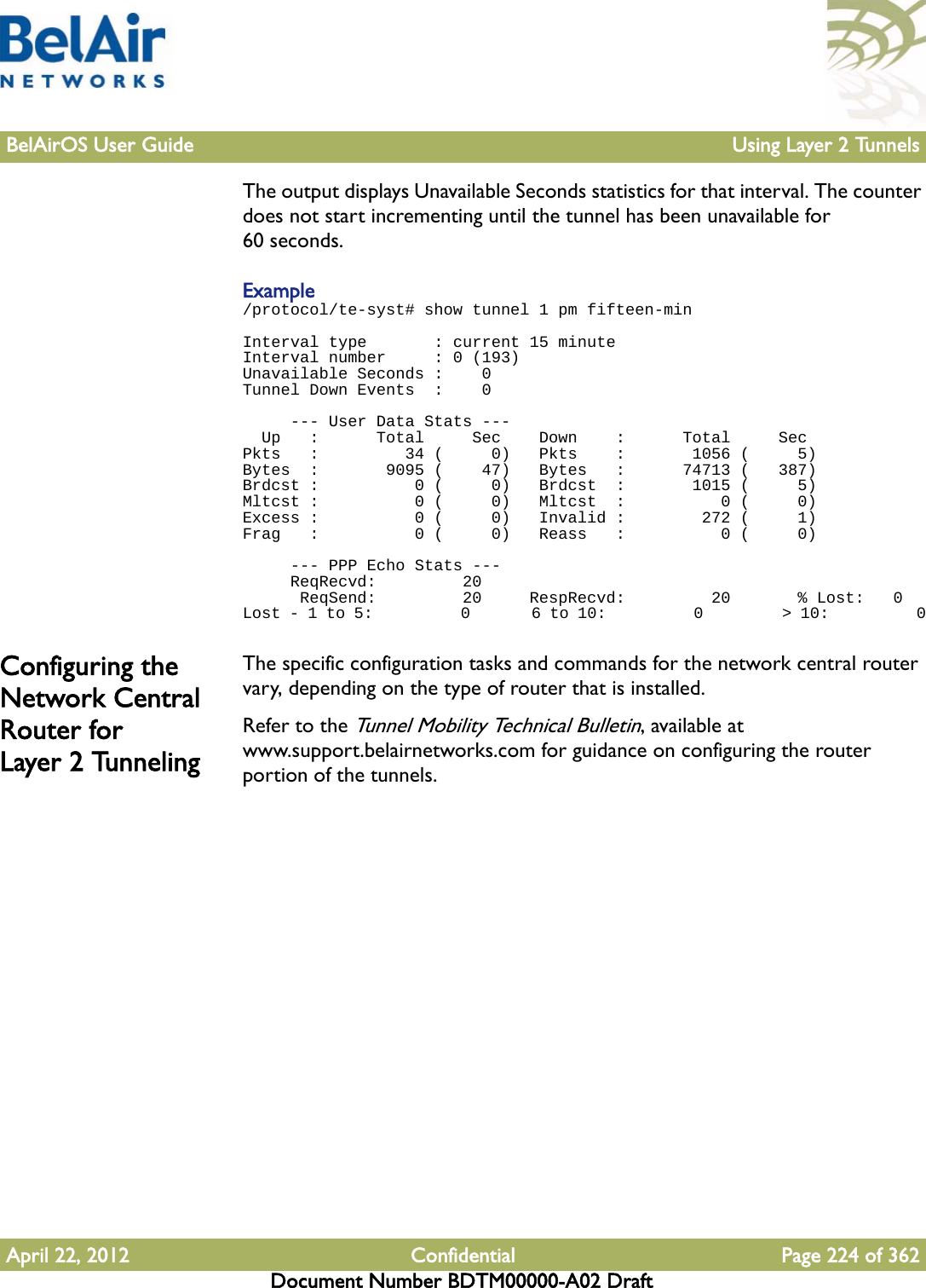

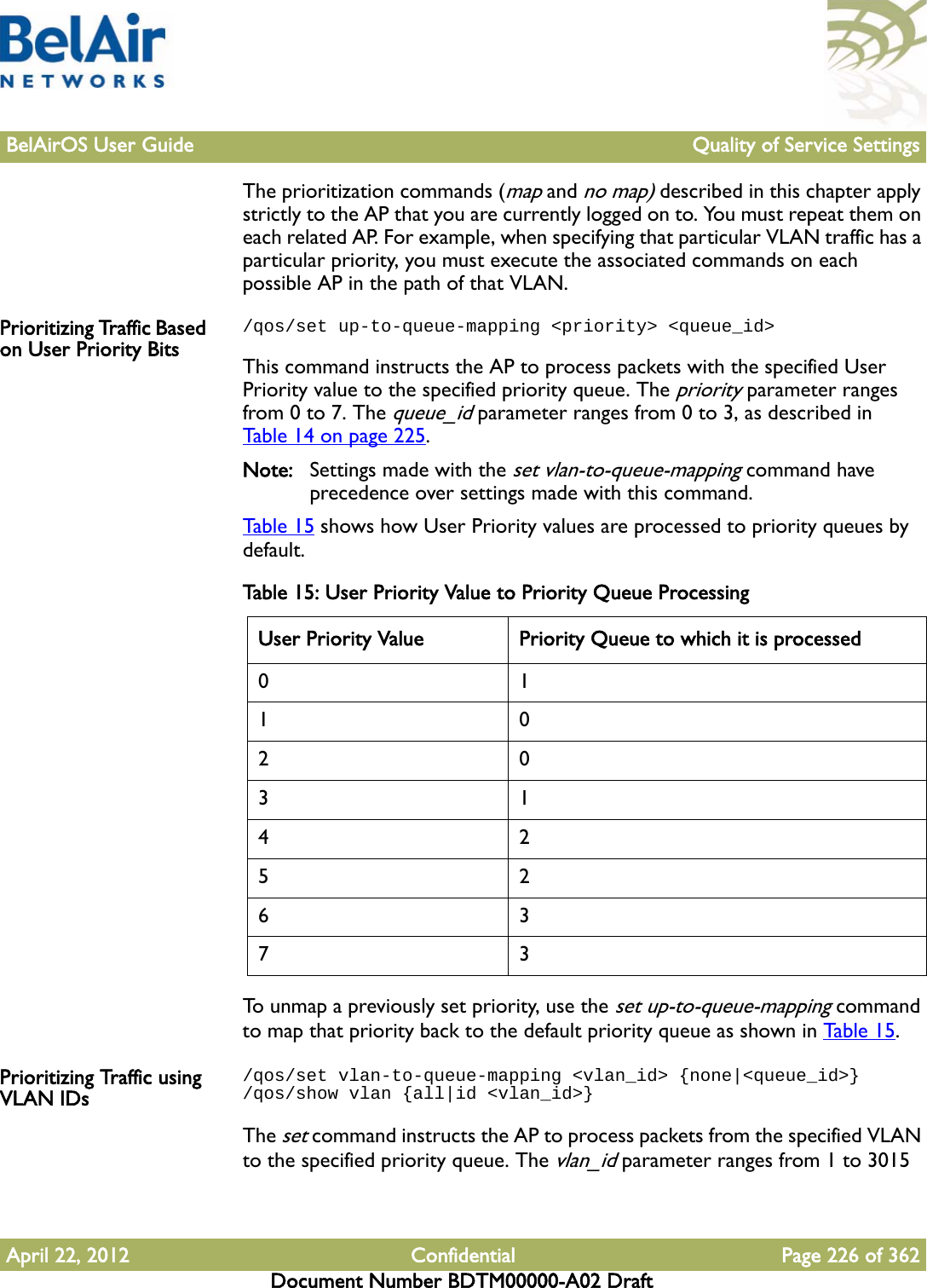
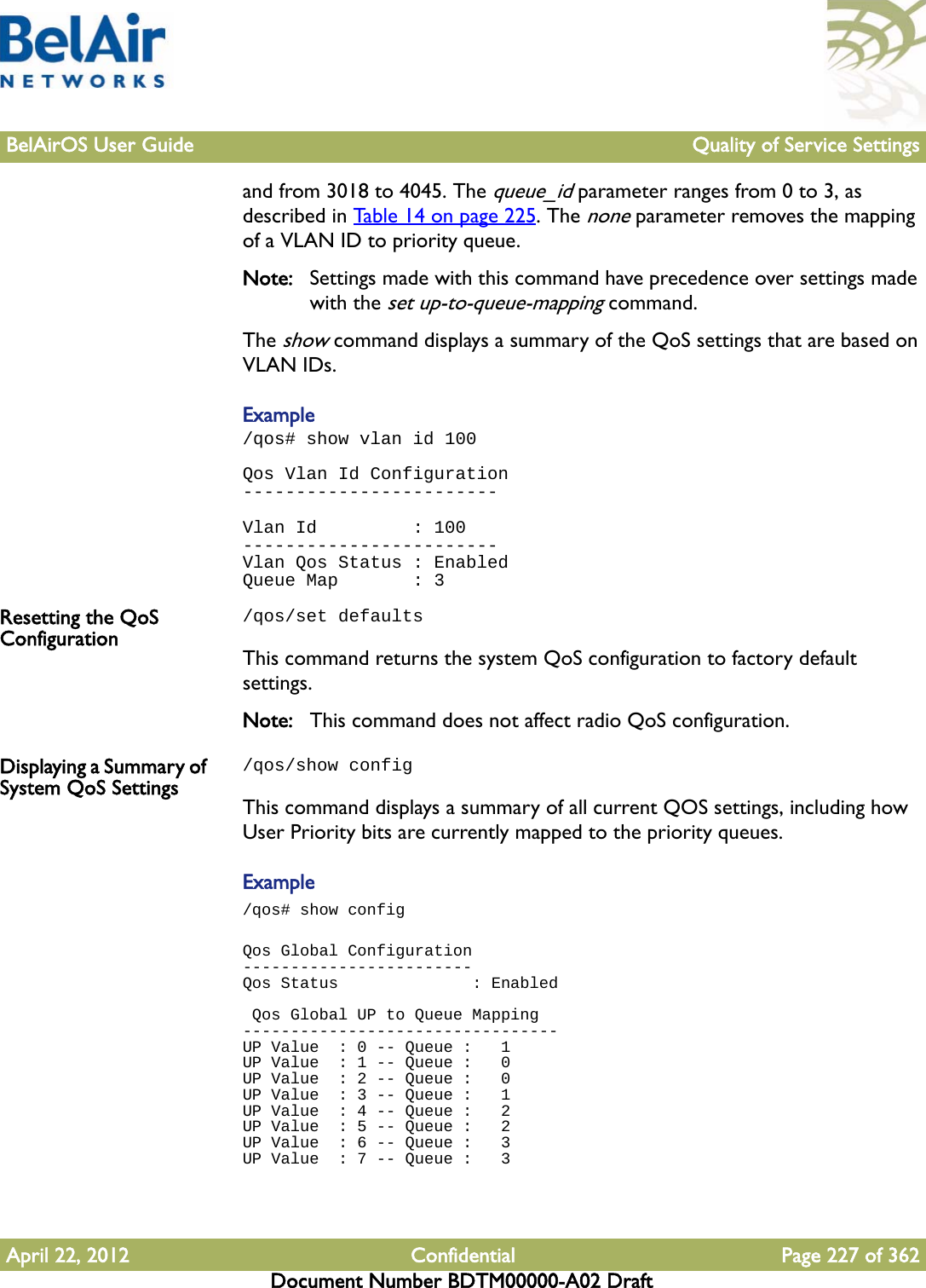
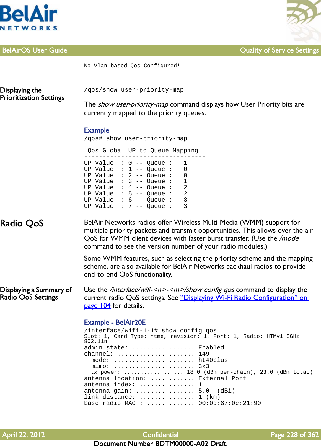
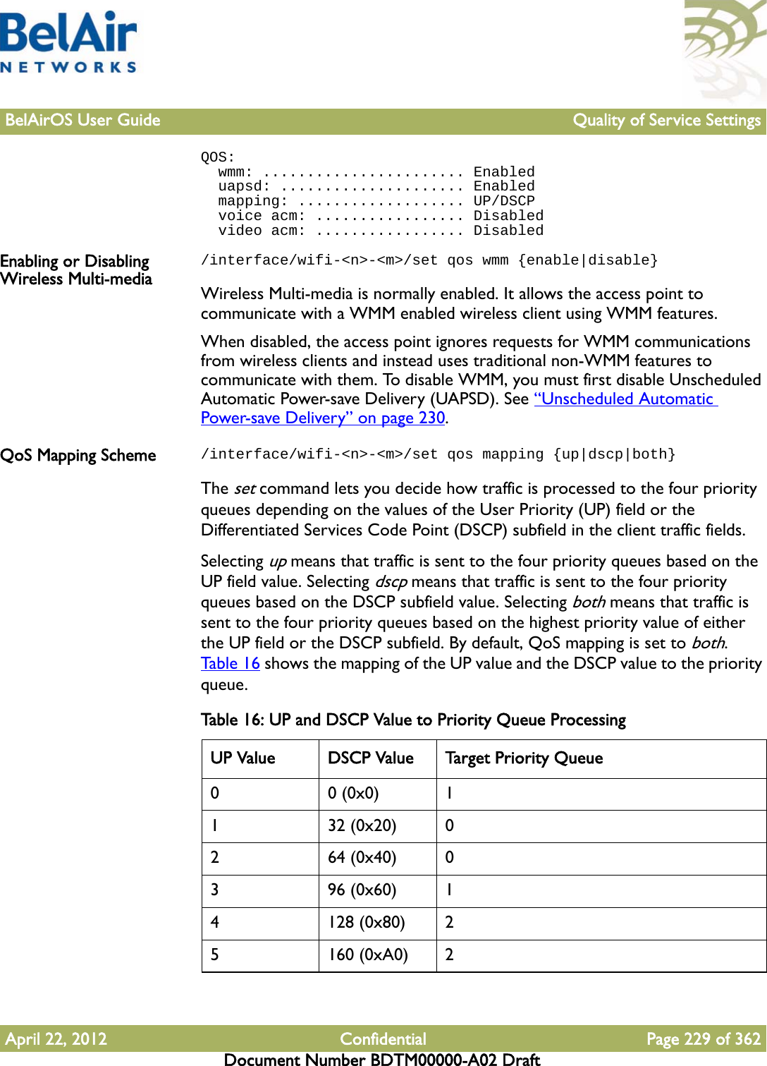
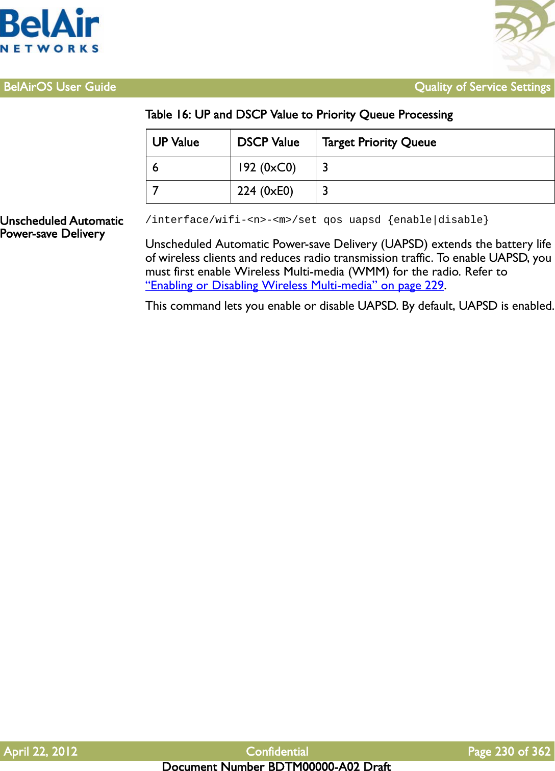
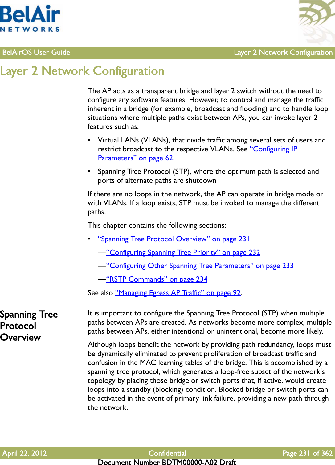
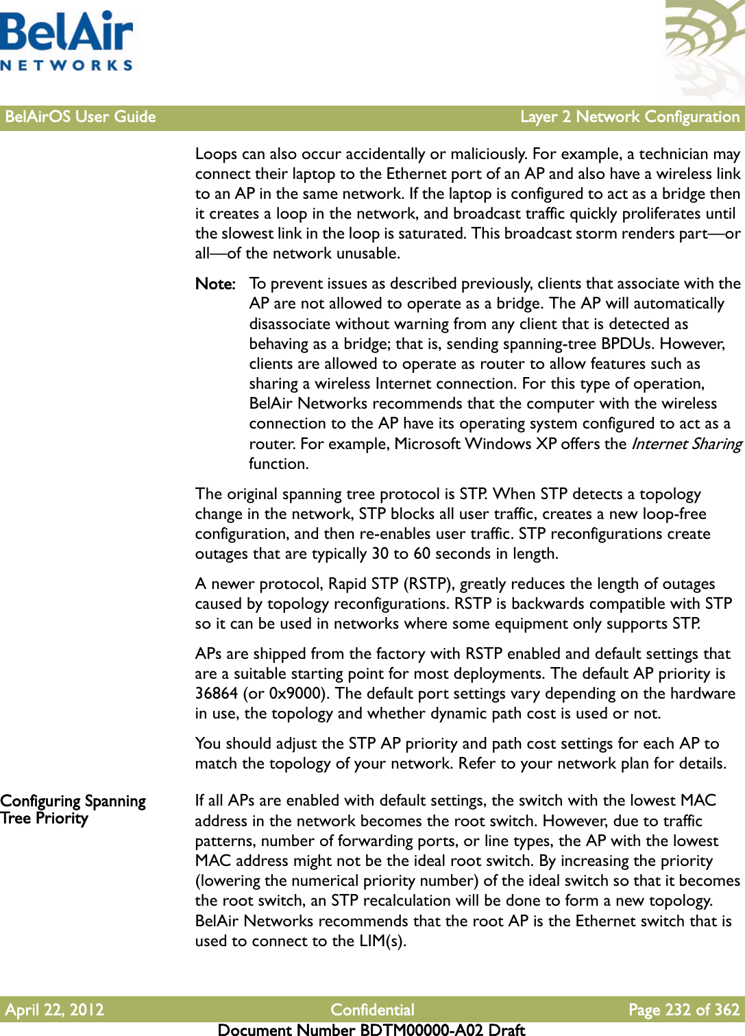
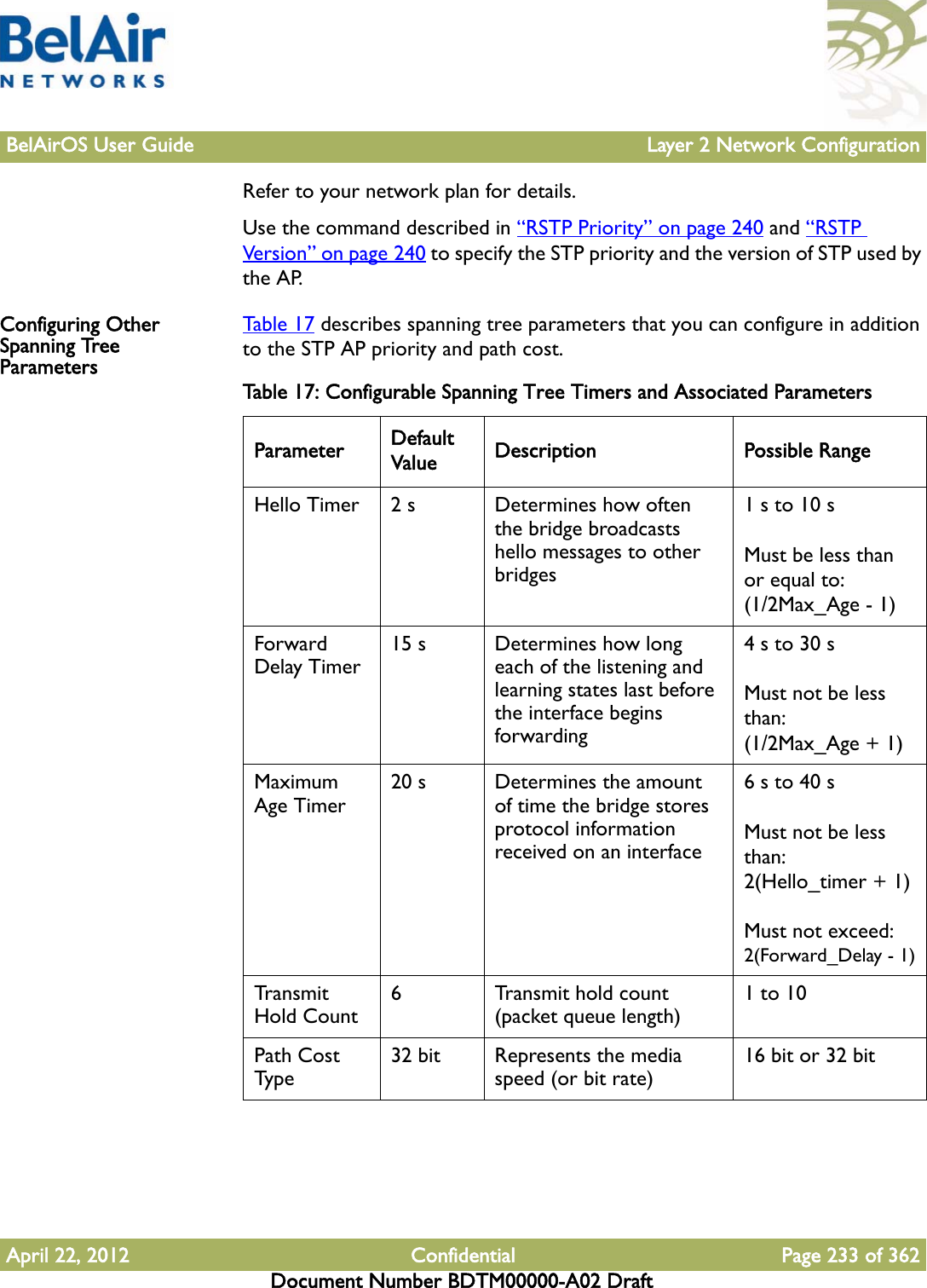
![BelAirOS User Guide Layer 2 Network ConfigurationApril 22, 2012 Confidential Page 234 of 362Document Number BDTM00000-A02 DraftNote: BelAir Networks recommends that you do not change the RSTP parameter values in Table 17 from their default values. Experience has shown that these default values work well in a variety of networks.To change the spanning tree transmit hold count and the path cost, refer to “Transmit Hold Count” on page 240. To change the values of the spanning-tree timers, refer to “Max Age, Hello Time and Forward Delay” on page 241.Note: The STP or RSTP parameter values that are actually used are inherited from the root bridge. When you configure STP or RSTP parameters on an AP, you are setting the values that are used if that AP is the root bridge.RSTP Commands This section describes commands that you can execute while in rstp mode. Some RSTP commands apply to specific physical interfaces or to specific radio links. The Name column of the /protocol/rstp/show config port all command displays available interfaces and radio links. For example, if the Name column displays wifi-3-1-1, then wifi-3-1 identifies the interface and the -1 suffix identifies radio link 1 of that interface.The AP layer 2 switch forwards layer 2 frames to the output of one or more physical interfaces or radio links based on the information contained in the frame header (tags).Displaying the RSTP Configuration Settings/protocol/rstp/show config [port {all|active|<interface-name>}]This command displays the currently configured RSTP settings. To see the currently active RSTP parameters, as inherited from the root bridge, use the /protocol/rstp/show config port active command.Link Detection Count3 Represents the number Hello timer periods to wait before declaring the link is down3 to the ratio of the Maximum Age timer to the Hello timerTable 17: Configurable Spanning Tree Timers and Associated Parameters Parameter Default Value Description Possible Range](https://usermanual.wiki/Ericsson-Wi-Fi/40005011.User-Manual/User-Guide-1698497-Page-234.png)
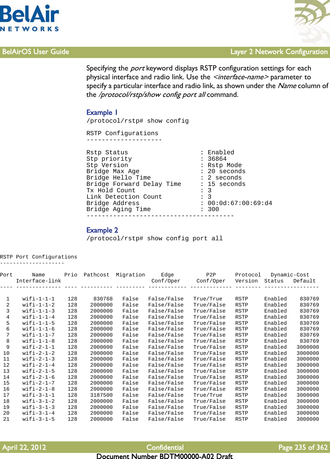
![BelAirOS User Guide Layer 2 Network ConfigurationApril 22, 2012 Confidential Page 236 of 362Document Number BDTM00000-A02 Draft 22 wifi-3-1-6 128 2000000 False False/False True/False RSTP Enabled 3000000 23 wifi-3-1-7 128 2000000 False False/False True/False RSTP Enabled 3000000 24 wifi-3-1-8 128 2000000 False False/False True/False RSTP Enabled 3000000 25 wifi-4-1-1 128 2000000 False False/False True/True RSTP Enabled 2000000 26 wifi-4-1-2 128 2000000 False False/False True/False RSTP Enabled 2000000 27 wifi-4-1-3 128 2000000 False False/False True/False RSTP Enabled 2000000 28 wifi-4-1-4 128 2000000 False False/False True/False RSTP Enabled 2000000 29 wifi-4-1-5 128 2000000 False False/False True/False RSTP Enabled 2000000 30 wifi-4-1-6 128 2000000 False False/False True/False RSTP Enabled 2000000 31 wifi-4-1-7 128 2000000 False False/False True/False RSTP Enabled 2000000 32 wifi-4-1-8 128 2000000 False False/False True/False RSTP Enabled 2000000 33 eth-5-1 128 200000 False False/False True/True RSTP Disabled 200000Example 3/protocol/rstp# show config port wifi-2-1-1RSTP Port Configurations--------------------Port Name Prio Pathcost Migration Edge P2P Protocol Dynamic-Cost Interface-link Conf/Oper Conf/Oper Version Status Default---- -------------- ---- ---------- --------- ------------ ------------- -------- ----------------- 9 wifi-2-1-1 128 2000000 False False/False True/False RSTP Enabled 3000000Example 4/protocol/rstp# show config port activeRSTP Port Configurations--------------------Port Name Prio Pathcost Migration Edge P2P Protocol Dynamic-Cost Interface-link Conf/Oper Conf/Oper Version Status Default---- -------------- ---- ---------- --------- ------------ ------------- -------- ----------------- 1 wifi-1-1-1 128 830768 False False/False True/True RSTP Enabled 830769 17 wifi-3-1-1 128 3187500 False False/False True/True RSTP Enabled 3000000 25 wifi-4-1-1 128 2000000 False False/False True/True RSTP Enabled 2000000 33 eth-5-1 128 200000 False False/False True/True RSTP Disabled 200000Displaying the RSTP Topology Information/protocol/rstp/show topology [port {all|active|<interface-name>}]This command displays the currently active RSTP parameters as inherited from the root bridge, including the MAC address of the designated root bridge in a network, the cost of the path to the root, the port used to message to the root bridge, as well as the current values of the spanning tree timers.To see the currently configured RSTP parameters, use the /protocol/rstp/show config command.](https://usermanual.wiki/Ericsson-Wi-Fi/40005011.User-Manual/User-Guide-1698497-Page-236.png)
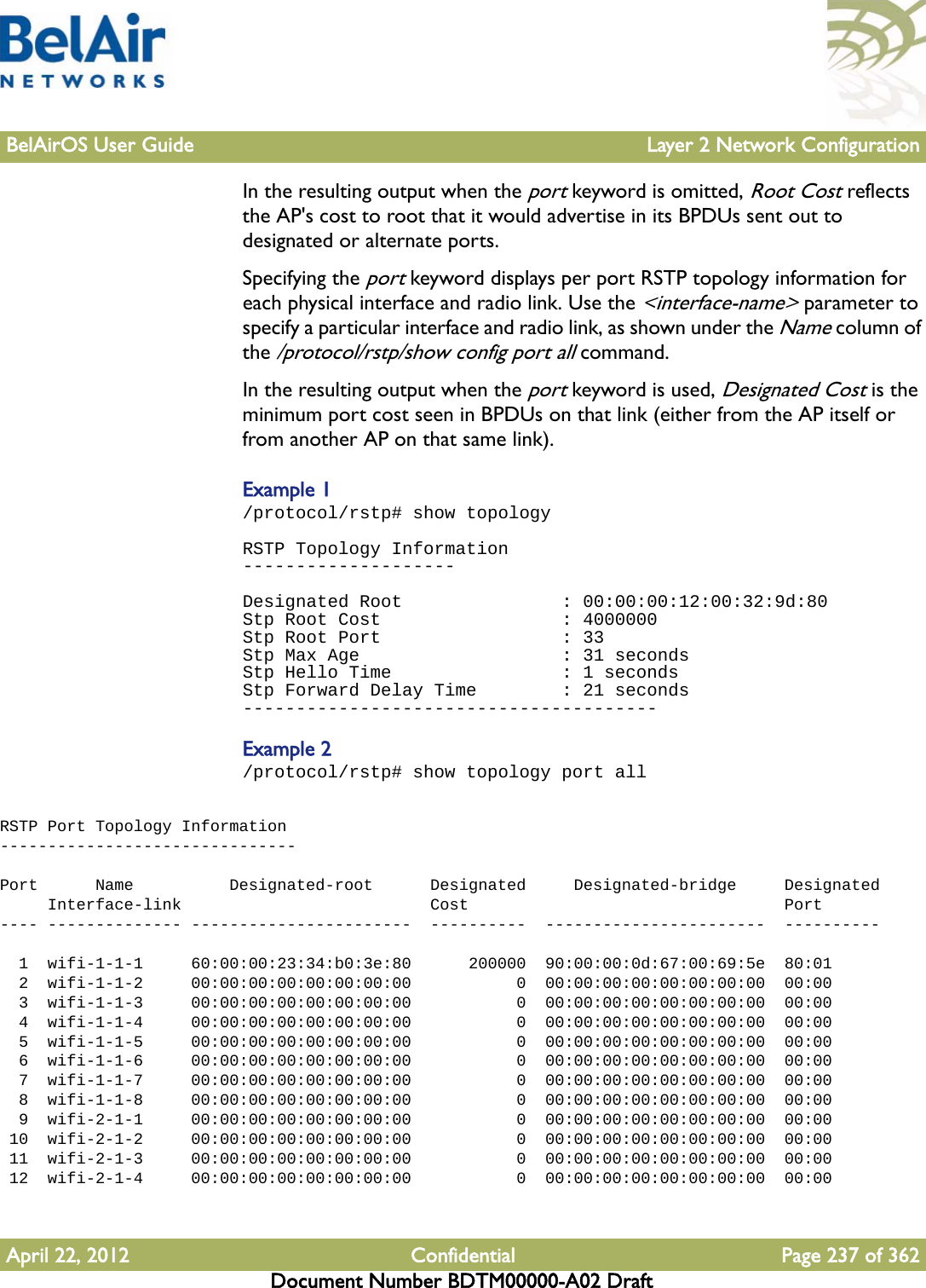
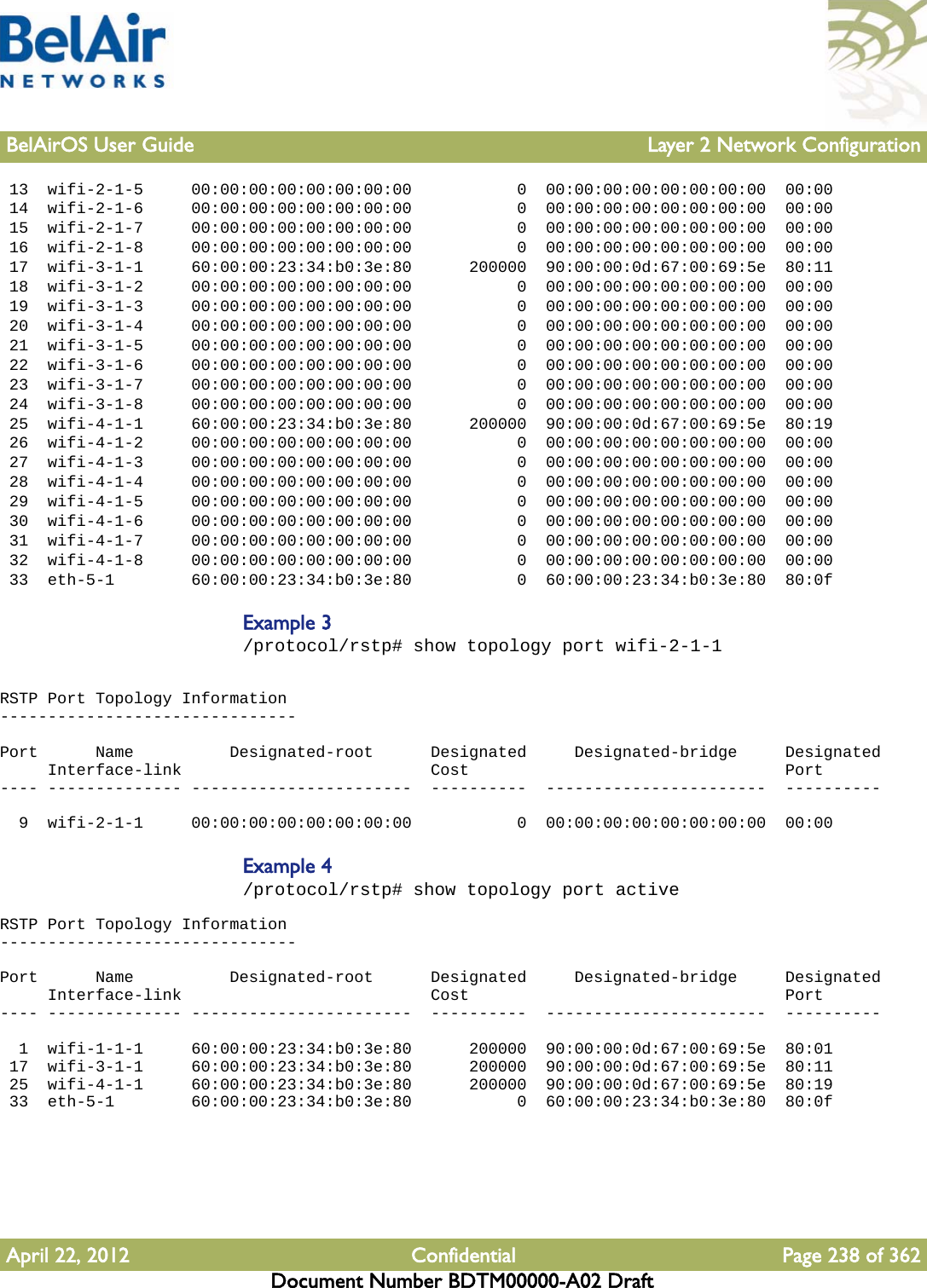
![BelAirOS User Guide Layer 2 Network ConfigurationApril 22, 2012 Confidential Page 239 of 362Document Number BDTM00000-A02 DraftDisplaying RSTP Port Roles and States/protocol/rstp/show port roles [all]This command displays the roles and states of the RSTP ports. Specifying the all option displays all possible links for a specific interface. If the all option is omitted, then the command outputs data only for links with a status of UP.Example 1/protocol/rstp# show port rolesRSTP Port Roles and States---------------------------Port# Name Remote-id Port-Role Port-State Port-Status----- ----------- --------------- ---------- ---------- --------- 9 wifi-2-1-1 10.5.1.22 Designated Forwarding Enabled 11 wifi-2-1-3 10.5.1.10 Designated Forwarding Enabled 17 wifi-3-1-1 10.5.1.13 Designated Forwarding Enabled 18 wifi-3-1-2 10.5.1.14 Designated Forwarding Enabled 25 wifi-4-1-1 10.5.1.25 Designated Forwarding Enabled 33 eth-1-1 Root Forwarding Enabled 34 eth-1-2 Designated Forwarding EnabledExample 2/protocol/rstp# show port roles allRSTP Port Roles and States---------------------------Port# Name Remote-id Port-Role Port-State Port-Status Link-status----- ----------- --------------- ---------- ---------- --------- ------------ 1 wifi-1-1-1 Disabled Discarding Enabled Down 2 wifi-1-1-2 Disabled Discarding Enabled Down 3 wifi-1-1-3 Disabled Discarding Enabled Down 4 wifi-1-1-4 Disabled Discarding Enabled Down 5 wifi-1-1-5 Disabled Discarding Enabled Down 6 wifi-1-1-6 Disabled Discarding Enabled Down 7 wifi-1-1-7 Disabled Discarding Disabled Down 8 wifi-1-1-8 Disabled Discarding Disabled Down 9 wifi-2-1-1 10.5.1.22 Designated Forwarding Enabled UP 10 wifi-2-1-2 Disabled Discarding Enabled Down 11 wifi-2-1-3 10.5.1.10 Designated Forwarding Enabled UP 12 wifi-2-1-4 Disabled Discarding Enabled Down 13 wifi-2-1-5 Disabled Discarding Enabled Down 14 wifi-2-1-6 Disabled Discarding Enabled Down 15 wifi-2-1-7 Disabled Discarding Enabled Down 16 wifi-2-1-8 Disabled Discarding Enabled Down 17 wifi-3-1-1 10.5.1.13 Designated Forwarding Enabled UP](https://usermanual.wiki/Ericsson-Wi-Fi/40005011.User-Manual/User-Guide-1698497-Page-239.png)
![BelAirOS User Guide Layer 2 Network ConfigurationApril 22, 2012 Confidential Page 240 of 362Document Number BDTM00000-A02 Draft 18 wifi-3-1-2 10.5.1.14 Designated Forwarding Enabled UP 19 wifi-3-1-3 Disabled Discarding Enabled Down 20 wifi-3-1-4 Disabled Discarding Enabled Down 21 wifi-3-1-5 Disabled Discarding Enabled Down 22 wifi-3-1-6 Disabled Discarding Enabled Down 23 wifi-3-1-7 Disabled Discarding Enabled Down 24 wifi-3-1-8 Disabled Discarding Enabled Down 25 wifi-4-1-1 10.5.1.25 Designated Forwarding Enabled UP 26 wifi-4-1-2 Disabled Discarding Enabled Down 27 wifi-4-1-3 Disabled Discarding Enabled Down 28 wifi-4-1-4 Disabled Discarding Enabled Down 29 wifi-4-1-5 Disabled Discarding Enabled Down 30 wifi-4-1-6 Disabled Discarding Enabled Down 31 wifi-4-1-7 Disabled Discarding Enabled Down 32 wifi-4-1-8 Disabled Discarding Enabled Down 33 eth-1-1 Root Forwarding Enabled UP 34 eth-1-2 Designated Forwarding Enabled UPConfiguring the Bridge Aging Time/protocol/rstp/set bridge aging-time <10 - 630>This command specifies the aging time, in seconds, for the dynamically learned forwarding information.RSTP Priority /protocol/rstp/set priority <Decimal (0 - 61440) or Hexadecimal (0x0000 -0xf000)>This command specifies the STP priority.The default AP priority is 36864 (or 0x9000). The priority values must be set in steps of 4096 (or 0x1000).RSTP Version /protocol/rstp/set version {stpCompatible|rstp}This command specifies the type of STP used by the AP.Setting the value to rstp mode forces it to transmit RST BPDUs while setting it to stpCompatible mode forces it to transmit configuration and TCN BPDUs. The default setting is rstp.Transmit Hold Count /protocol/rstp/set [tx-holdcount (1 - 10)]This command configures the values of transmit hold count. The transmit hold count value indicates the number of BPDUs that need to be transmitted in any Hello Time interval. The default value is 6.](https://usermanual.wiki/Ericsson-Wi-Fi/40005011.User-Manual/User-Guide-1698497-Page-240.png)
![BelAirOS User Guide Layer 2 Network ConfigurationApril 22, 2012 Confidential Page 241 of 362Document Number BDTM00000-A02 DraftNote: BelAir Networks recommends that you do not change the RSTP parameter values from their default values. Experience has shown that the default values work well in a variety of networks.Example/protocol/rstp# set tx-holdcount 5Max Age, Hello Time and Forward Delay/protocol/rstp/set ([max-age <6 - 40>] [hello-time <1 - 10>] [forward-delay <4 - 30>])The max-age field represents the time in seconds that all bridges use for MaxAge when this bridge is acting as the root. The default value is 20. The value must not exceed: 2(ForwardDelay -1).The hello-time field represents the time in seconds that all bridges use for HelloTime when this bridge is acting as the root. The default value is 2.The forward-delay field represents the time in seconds that all bridges use for ForwardDelay when this bridge is acting as the root. The default value is 15. The value must not be less than: 1 + 1/2 MaxAge.Note: BelAir Networks recommends that you do not change the RSTP parameter values from their default values. Experience has shown that the default values work well in a variety of networks.Example/protocol/rstp# set max-age 20 hello-time 2 forward-delay 15RSTP Link Priority /protocol/rstp/set interface <interface-name> priority <Decimal (0-240) or Hexadecimal (0x00 -0xF0)>This command configures the link priority. This command is available only if dynamic path costs are disabled. Refer to “Dynamic Path Cost” on page 242.The <interface-name> parameter specifies a particular interface, such as wifi-2-1.The link priority value forms the first component or the portion of the Port ID that can be written. The values for the link priority must only be in steps of 16 (only the first 4 bits can be set for the link priority).Example/protocol/rstp# set interface wifi-2-1 priority 64](https://usermanual.wiki/Ericsson-Wi-Fi/40005011.User-Manual/User-Guide-1698497-Page-241.png)
![BelAirOS User Guide Layer 2 Network ConfigurationApril 22, 2012 Confidential Page 242 of 362Document Number BDTM00000-A02 DraftRSTP Static Path Cost /protocol/rstp/set interface <interface-name> defaultcost <1 - 200000000>This command sets the static path cost in the pathcost field. This command is available only if dynamic path costs are disabled. Refer to “Dynamic Path Cost” on page 242.The <interface-name> parameter specifies a particular interface, such as wifi-2-1.The static path cost determines the preferred data paths between bridges throughout the network and the root bridge. The default path cost settings vary, depending on the hardware in use, the topology and whether dynamic path cost is used or not.Example/protocol/rstp# set interface wifi-2-1 pathcost 65535Dynamic Path Cost /protocol/rstp/set interface <interface-name> [dynamic-cost {enabled|disabled}]This command lets you manage how path costs are determined for each radio link on your AP.The <interface-name> parameter specifies a particular interface, such as wifi-2-1.Dynamic path costs are a useful way to adjust the topology of a network to isolate a link as a result of unplanned or seasonal effects. For example, there may be an unplanned source of radio interference with a particular link. Or, vegetation may affect a link during summer.When dynamic cost is disabled, each link is assigned a fixed cost. The default value depends on the hardware and topology in use.When dynamic cost is enabled, the AP adjusts the link’s cost based on several link quality factors. For example, a link with a low RSSI, such as -80, implies poor link quality causing it to have an increased cost. Similarly, a link with a high RSSI, such as -40, implies good link quality causing it’s cost to be reduced. Enabling dynamic path costs disables the command to configure a static path cost. Refer to “RSTP Static Path Cost” on page 242.To prevent unnecessary topology changes based on transient behaviour, a new link cost may not automatically cause a topology change. If the new link cost is very different from the current link cost, then the topology is changed.](https://usermanual.wiki/Ericsson-Wi-Fi/40005011.User-Manual/User-Guide-1698497-Page-242.png)
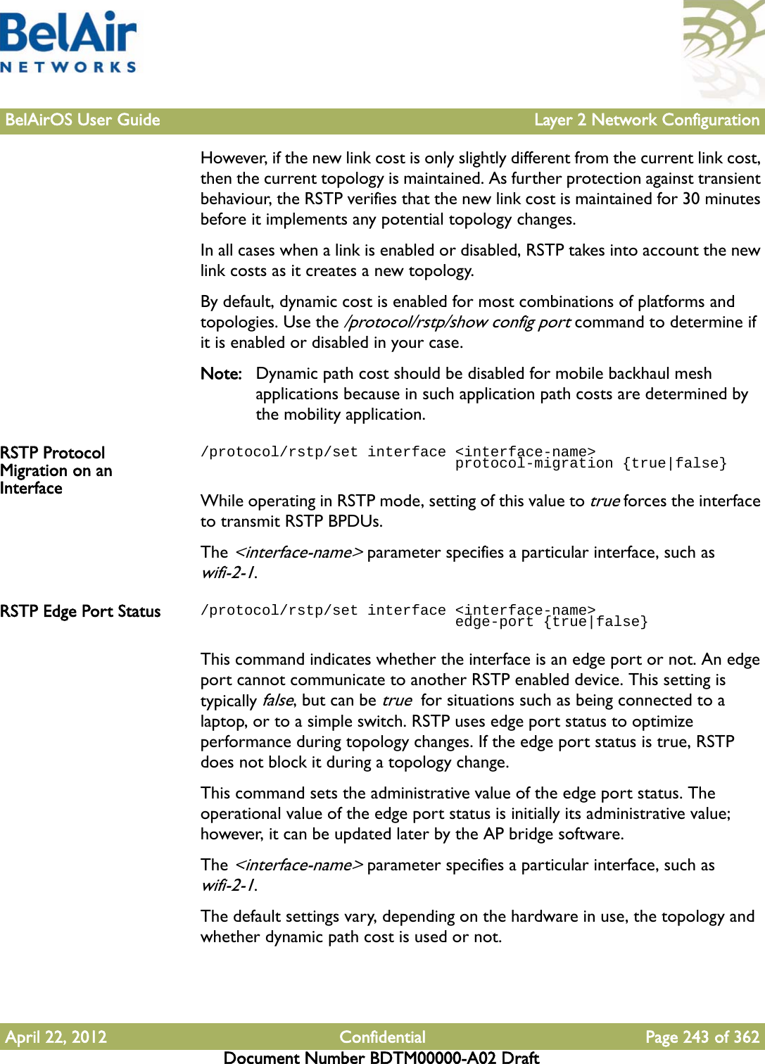
![BelAirOS User Guide Layer 2 Network ConfigurationApril 22, 2012 Confidential Page 244 of 362Document Number BDTM00000-A02 DraftRSTP Point-To-Point Status of an Interface/protocol/rstp/set interface <interface-name> p2p {forcetrue|forcefalse}This command indicates whether the interface can do RSTP point-to-point communications or not. RSTP point-to-point communications is special case where the interface can communicate with only one other RSTP enabled device, such as when only two APs are connected through a simple switch. RSTP uses RSTP point-to-point status to optimize performance during topology changes.This command sets the administrative value of the RSTP point-to-point status. The operational value of the RSTP point-to-point status is initially its administrative value; however, it can be updated later by the AP bridge software.The <interface-name> parameter specifies a particular interface, such as wifi-2-1.Setting a value of forcetrue forces it to function as a point-to-point link. Setting a value of forcefalse forces it not to function as a point-to-point link. The default settings vary, depending on the hardware in use, the topology and whether dynamic path cost is used or not.Interface RSTP Configuration/protocol/rstp/set interface <interface-name> admin-state {enable|disable}This command allows or prevents RSTP from affecting the specified interface. The <interface-name> parameter specifies a particular interface, such as wifi-2-1.By default, RSTP affects all enabled interfaces. Setting admin-state to disable prevents RSTP from affecting this interface. Setting admin-state to enable allows RSTP to affect this interface.Changing RSTP Admin State/protocol/rstp/set admin-state {enabled|disabled}This command lets you enable or disable RSTP functionality. The default setting is enabled.RSTP Statistics /protocol/rstp/show stats [port {all|active|<interface-name>}]This command displays RSTP-related bridge statistics.](https://usermanual.wiki/Ericsson-Wi-Fi/40005011.User-Manual/User-Guide-1698497-Page-244.png)
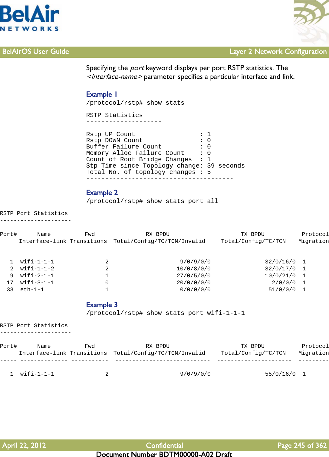
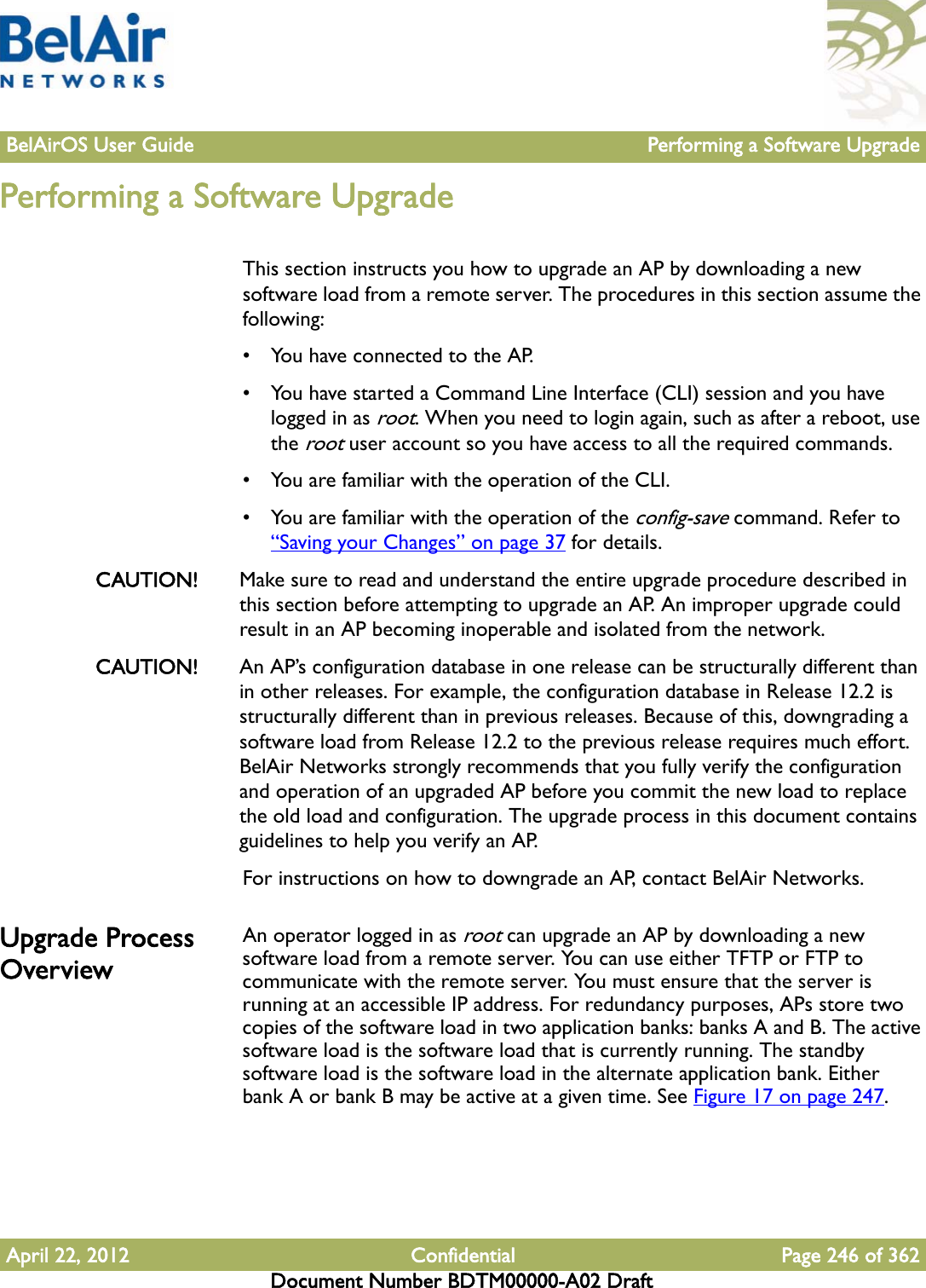
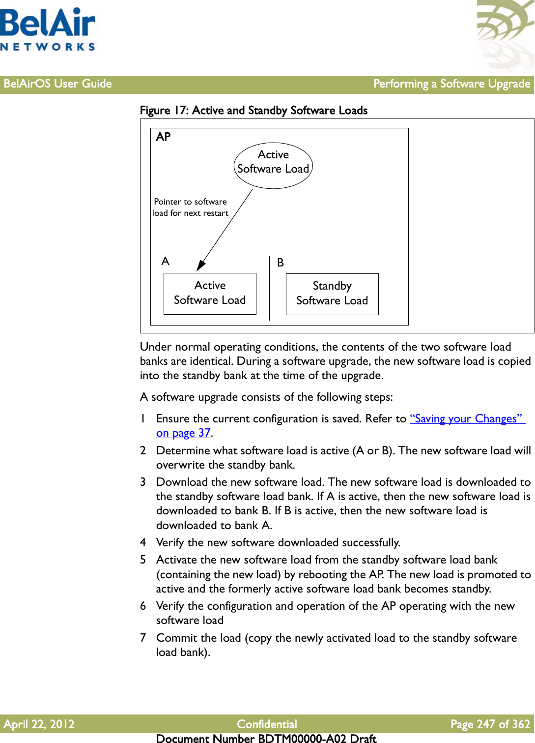
![BelAirOS User Guide Performing a Software UpgradeApril 22, 2012 Confidential Page 248 of 362Document Number BDTM00000-A02 DraftNote: Any configuration changes that you make before you commit the new software load are lost if you back out of the upgrade. You can also use BelView NMS to manage how APs are upgraded. For details, refer to the BelView NMS User Guide and “Auto-upgrade” on page 253.CAUTION! Do not change or save the AP configuration while upgrading the system.CAUTION! It is always possible to downgrade a committed software load to an older release. However, while the existing configuration data is saved (upgraded) during a software upgrade, the existing configuration data could be lost (erased) during a software downgrade. BelAir Networks recommends that you save and remotely store the current existing configuration database in case you choose to downgrade a software load. For instructions on how to downgrade an AP, contact BelAir Networks. Displaying the Active and Next Software LoadsDisplay the active software load and the load that is activated at the next reboot with the following command:/system/show loadsDownloading a New Software Load/system/upgrade load remoteip <serverIPaddress> remotepath <serverSubDir> [{tftp|ftp [user <usrname> password <pword>]}]]This command downloads a new software image from a remote server. It copies the new software load into the standby software load bank and sets the new load as the next active load. See Figure 18 on page 249.You can use either TFTP or FTP to communicate with the remote server. By default, the upgrade load command uses TFTP. If you specify FTP, you can also specify the user name and password. The default FTP user name is anonymous and the default FTP password is root@<nodeip>, where <nodeip> is the IP address of AP making the request. If you do not use the default FTP username, the FTP server must be configured to accept your username and password.CAUTION! Once it begins, the upgrade process cannot be interrupted or terminated by the user with the current CLI session. See “Canceling a Software Upgrade” on page 248.](https://usermanual.wiki/Ericsson-Wi-Fi/40005011.User-Manual/User-Guide-1698497-Page-248.png)
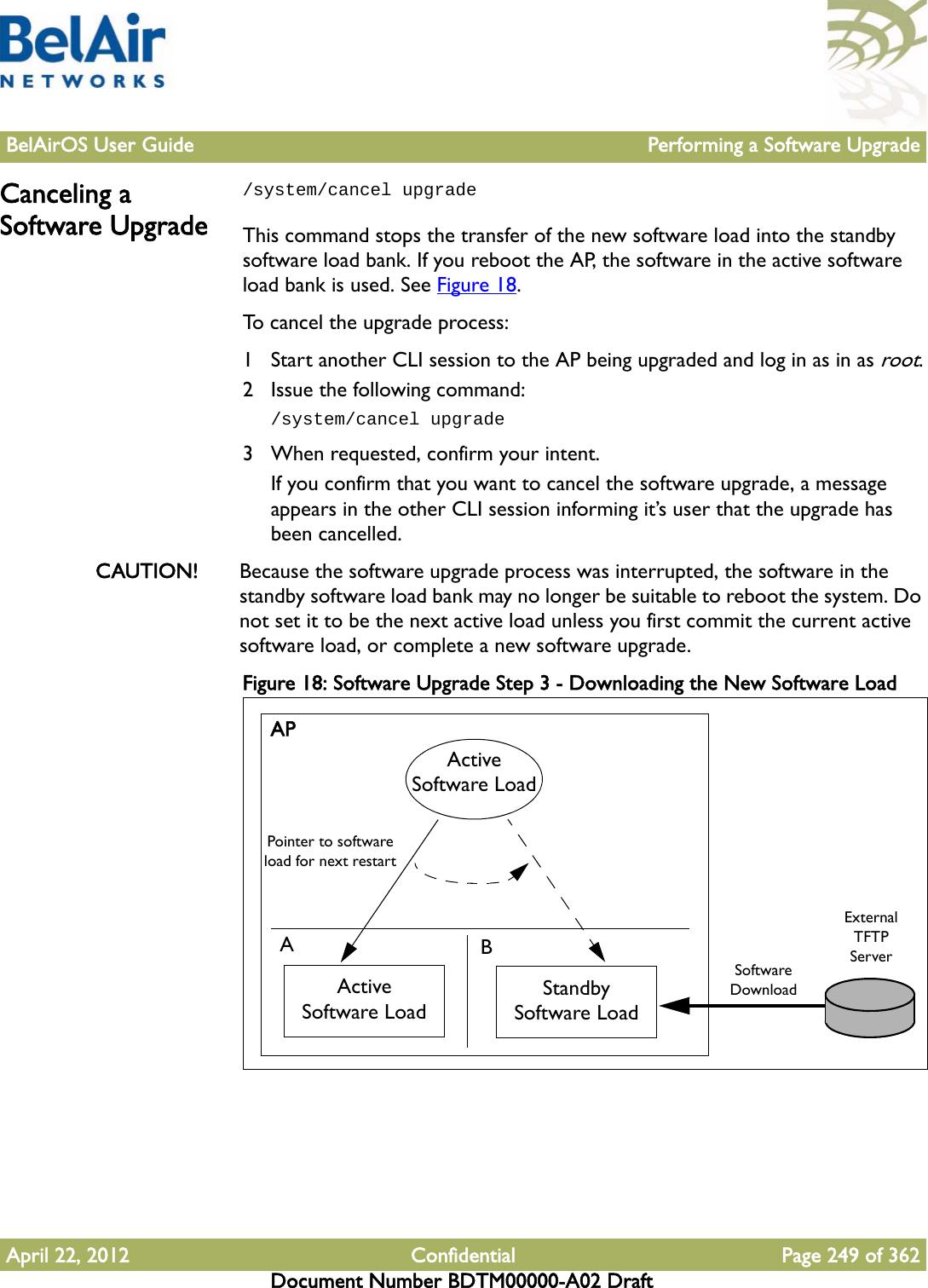
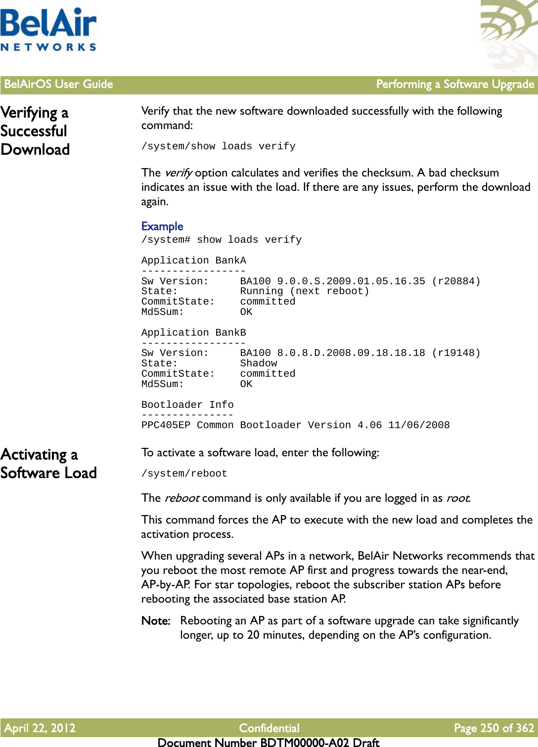
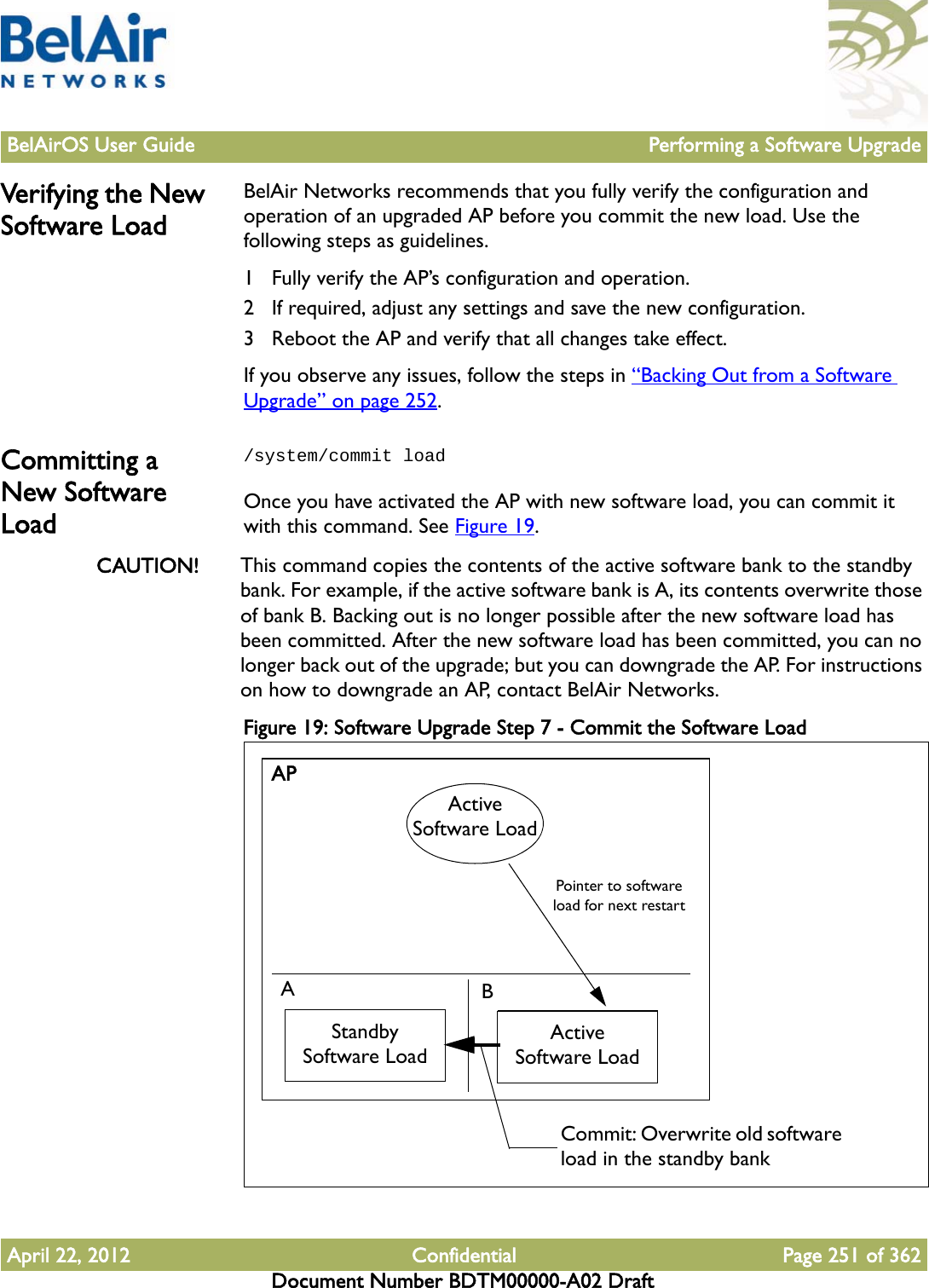
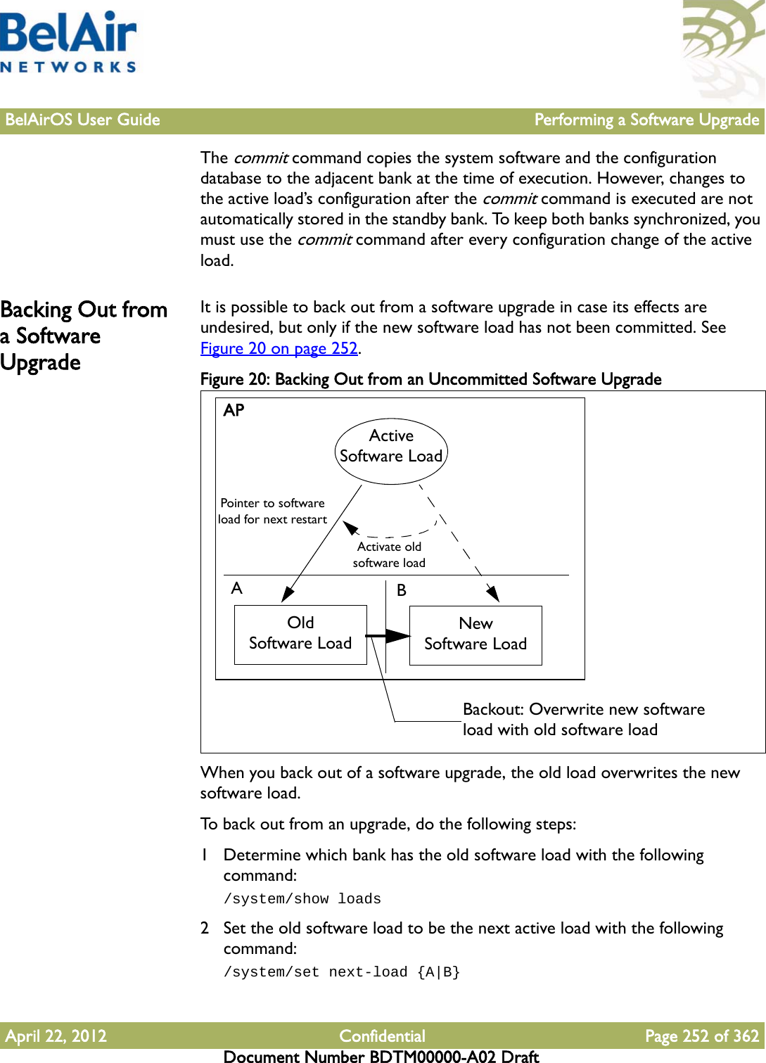
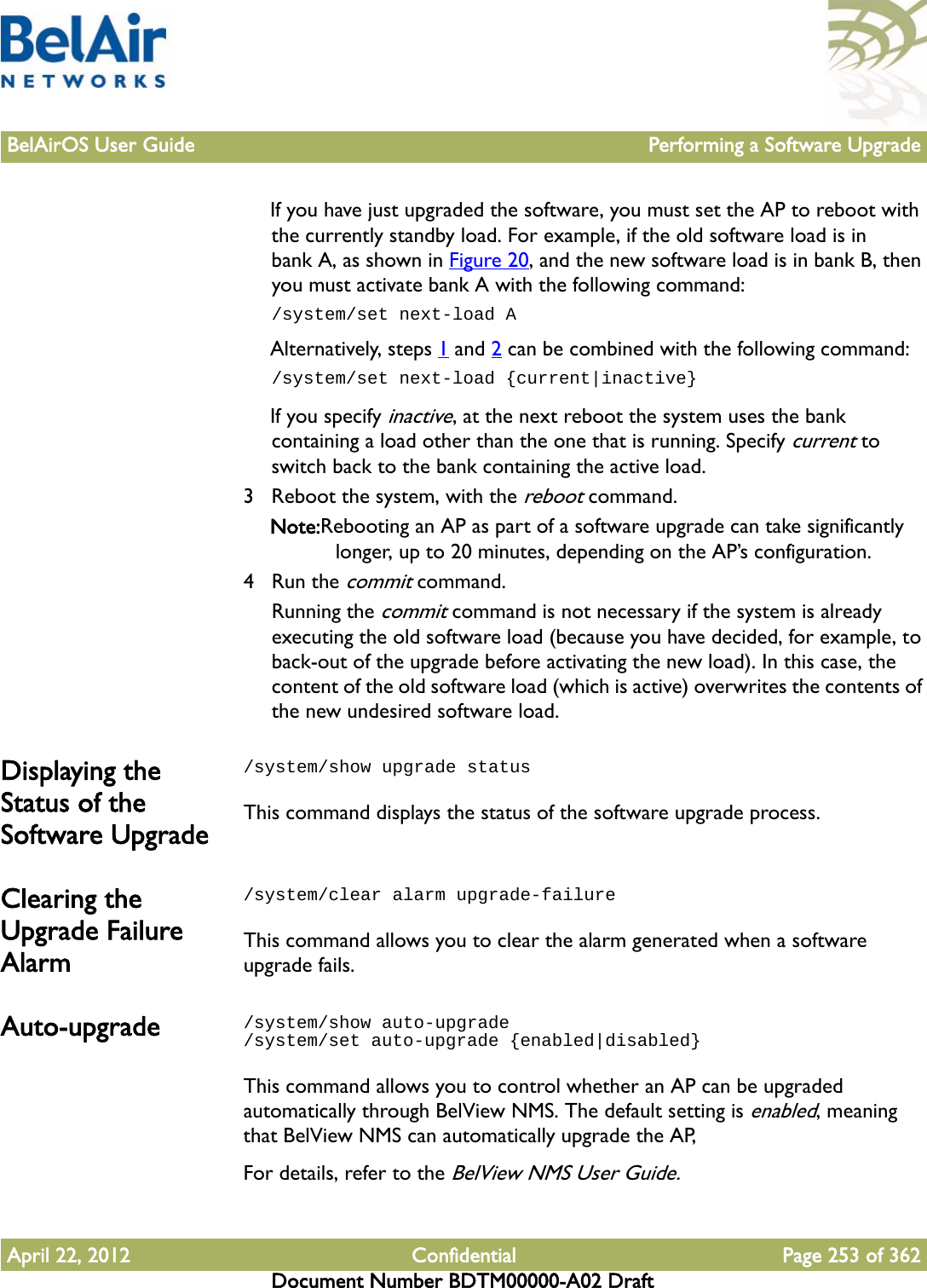
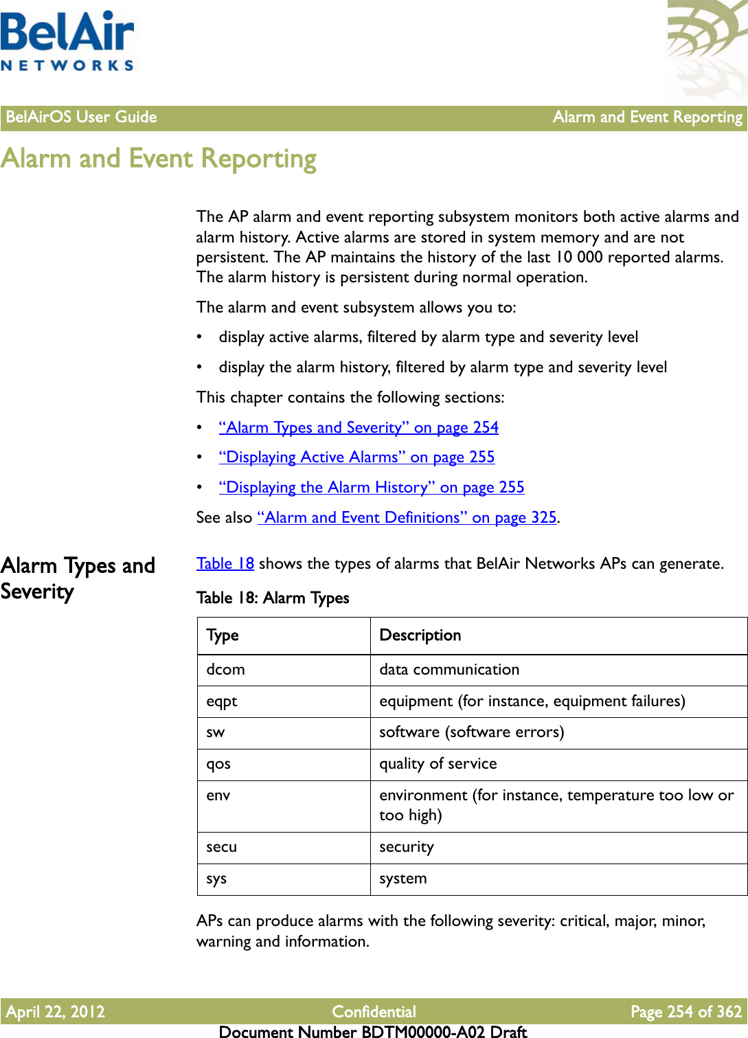
![BelAirOS User Guide Alarm and Event ReportingApril 22, 2012 Confidential Page 255 of 362Document Number BDTM00000-A02 DraftDisplaying Active Alarms/system/show alarms <max_num_of_alarms> [type {all|dcomm|eqpt|sw|qos|env|secu|sys}] [severity {all|critical|major|minor|warning|info}]This command allows you to display up to “n” active alarms, filtered by alarm type or alarm severity. If the alarm severity is to be specified, then the alarm type must also be specified, but can be specified as all if no filtering by type is desired.The type and severity specifications can have multiple values separated by a vertical bar. For example, specifying type dcom|eqpt|env shows all data communications, equipment and environment alarms.In the active alarm display:• The Id field indicates the log index number.• The Ignored field indicates whether or not a Syslog and SNMP trap notification was sent for this item. ExampleIn the following example, only one alarm is displayed because only one alarm was active at the time the command was issued./# system/show alarms 20Displaying 1 active alarms of 1 total:Id Date/Time (UTC) Severity Status Ignored Entity Type Description----------------------------------------------------------------------------------------------0 2004-11-05 19:16:06 critical Set No brm1 dcom Link DownDisplaying the Alarm History/system/show alarm history <max_num_of_alarms> [type {all|dcomm|eqpt|sw|qos|env|secu|sys}] [severity {all|critical|major|minor|warning|info}] [<log_idx>]This command allows you to display up to the last “n” reported alarms, filtered by alarm type or alarm severity. If the alarm severity is to be specified, then the alarm type must also be specified, but can be specified as all if no filtering by type is desired.The type and severity specifications can have multiple values separated by a vertical bar. For example, specifying type dcom|eqpt|env shows all data communications, equipment and environment alarms.The <log_idx> parameter specifies the most recent alarm log to display. It defaults to the last index generated.](https://usermanual.wiki/Ericsson-Wi-Fi/40005011.User-Manual/User-Guide-1698497-Page-255.png)
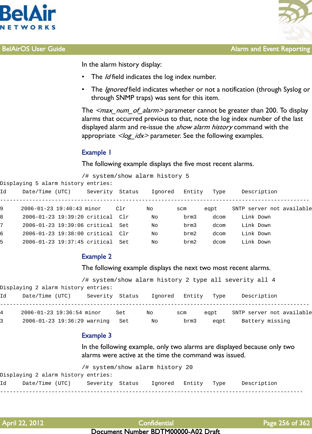
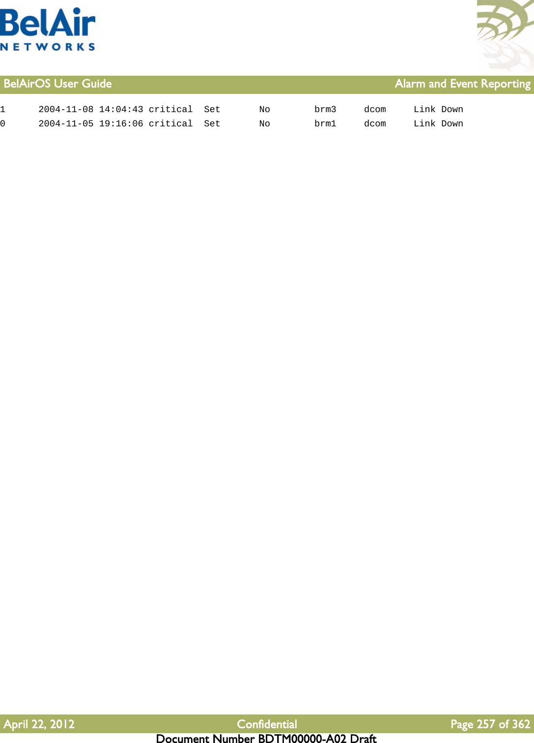
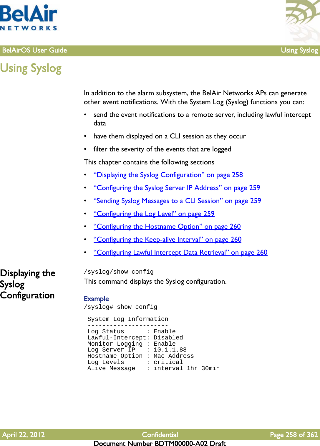
![BelAirOS User Guide Using SyslogApril 22, 2012 Confidential Page 259 of 362Document Number BDTM00000-A02 DraftConfiguring the Syslog Server IP Address/syslog/logserver {enable [<ip address>] |disable}This command sets the Syslog server IP address for remote logging. Only one server can be defined at a time. If a different IP address was configured before, this command closes the previous connection. Use the disable parameter to remove a Syslog server.Example/syslog# logserver enable 10.6.4.52Sending Syslog Messages to a CLI Session/syslog/monitor logging {enable|disable}This command instructs the AP to send Syslog messages to the current CLI session for display as they are generated. If you continue to use the current CLI session, the Syslog messages are interleaved with regular command input and output.This command affects only the current CLI session. A new CLI session does not have this option enabled. This feature allows the Syslog messages to be displayed in one CLI session while another CLI session is used for regular command input and output.To use this feature, you must first enable a log server with the logserver {enable [<ip address>] command.Enabling this feature disables the normal CLI session inactivity timer. The CLI session remains open until this feature is explicitly disabled.Example/syslog# monitor logging enableConfiguring the Log Level/syslog/loglevel {debug|info|notice|warn|error| critical|alert|emerg}This command defines the maximum severity level for messages to be sent to the remote Syslog server or the CLI session. (See “Configuring the Syslog Server IP Address” on page 259 and “Sending Syslog Messages to a CLI Session” on page 259.)This command restricts logging to messages at the specified level and below (in the sequence of appearance in the command). Note: The Syslog message severity levels are separate and distinct from the alarm severity levels.The default level is error.](https://usermanual.wiki/Ericsson-Wi-Fi/40005011.User-Manual/User-Guide-1698497-Page-259.png)
![BelAirOS User Guide Using SyslogApril 22, 2012 Confidential Page 260 of 362Document Number BDTM00000-A02 DraftExample/syslog# loglevel errorIn the preceding example, after the command is issued, the AP generates error, critical, alert and emerg messages.Configuring the Hostname Option/syslog/set hostname-type {ip-address|mac-address}This command lets you send the host name as either an IP address or a MAC address. The default is to send the host name as an IP address.Configuring the Keep-alive Interval/syslog/set alive-message {disable | enable interval [hr <hrs>] [min <mins>]}This command lets you send a keep-alive message to the remote Syslog server at a regular interval. The interval should not be shorter than 1 minute.Configuring Lawful Intercept Data Retrieval/syslog/set lawful-intercept {enable|disable}This command lets you gather network data pursuant to lawful authority for the purpose of analysis or evidence. Specifically, when Network Address Translation (NAT) is enabled, many wireless clients can share a single public IP address. By enabling lawful intercept data retrieval, the gathered Syslog data contains the public IP address being used as well as the wireless client IP address and MAC address. The additional data is delivered in log entries with a severity level of warning.By default, lawful intercept data retrieval is disabled.To enable lawful intercept data retrieval:1 Ensure NAT is enabled. If NAT is disabled, the /syslog/set lawful-intercept command is disabled automatically. See “Network Address Translation” on page 196.2 Ensure Syslog is enabled:/syslog# logserver enable 10.1.1.883 Enabled lawful intercept data retrieval:/syslog# set lawful-intercept enableLawful Intercept is enabled4 Ensure the log level is correct:/syslog# loglevel warn](https://usermanual.wiki/Ericsson-Wi-Fi/40005011.User-Manual/User-Guide-1698497-Page-260.png)
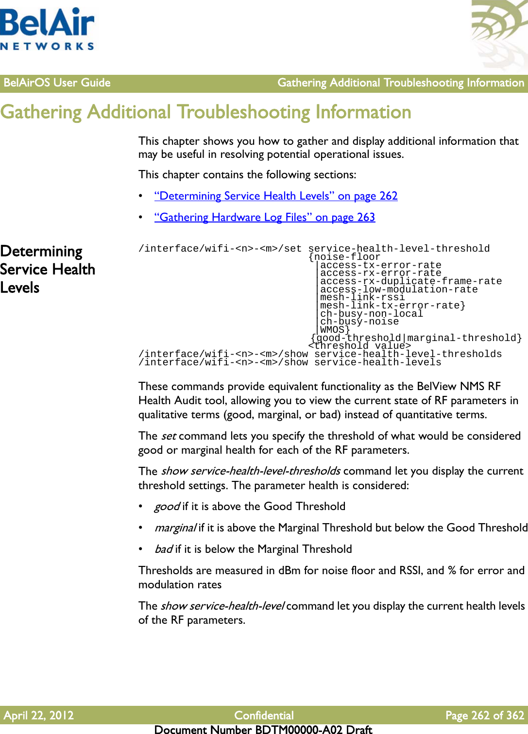
![BelAirOS User Guide Gathering Additional Troubleshooting InformationApril 22, 2012 Confidential Page 263 of 362Document Number BDTM00000-A02 DraftExample 1/interface/wifi-1-2# show service-health-level-thresholdsThreshold Type Good Threshold Marginal Threshold---------------------------------------------------------------------Noise Floor -90 -80Access Tx Error Rate 10 25Access Rx Error Rate 10 25Access Rx Duplicate Error Rate 10 25Access Low Modulation Rate 10 25Mesh Link RSSI -75 -80Mesh Link Tx Error Rate 10 25Example 2/interface/wifi-1-2# show service-health-levels Health Level Type Health Level----------------------------------------------------------------------- Noise Floor Good Access Tx Error Rate Good Access Rx Error Rate Good Access Rx Duplicate Error Rate Good Access Low Modulation Rate Good Mesh Link RSSI: Link 1: ................... Unknown Link 2: ................... Unknown Link 3: ................... Unknown Link 4: ................... Unknown Link 5: ................... Unknown Link 6: ................... Unknown Link 7: ................... Unknown Link 8: ................... Unknown Mesh Link Tx Error Rate: Link 1: ................... Unknown Link 2: ................... Unknown Link 3: ................... Unknown Link 4: ................... Unknown Link 5: ................... Unknown Link 6: ................... Unknown Link 7: ................... Unknown Link 8: ................... UnknownGathering Hardware Log FilesBelAir Networks hardware generates its own operational log files, recording information in a custom format. This information may be used by your BelAir Networks representative to identify a potential issue.TFTP Transfer of Internal Log Files/syslog/export logs remoteip <IP_addr> [flightrecorder] [logs] [commands] [slot <slot_no>] [filter <string>]This command instructs the AP to package internal operational and state data into a flight recorder file, a log file and a commands file, and send them to a remote file system through TFTP. The resulting files can then be analyzed by](https://usermanual.wiki/Ericsson-Wi-Fi/40005011.User-Manual/User-Guide-1698497-Page-263.png)
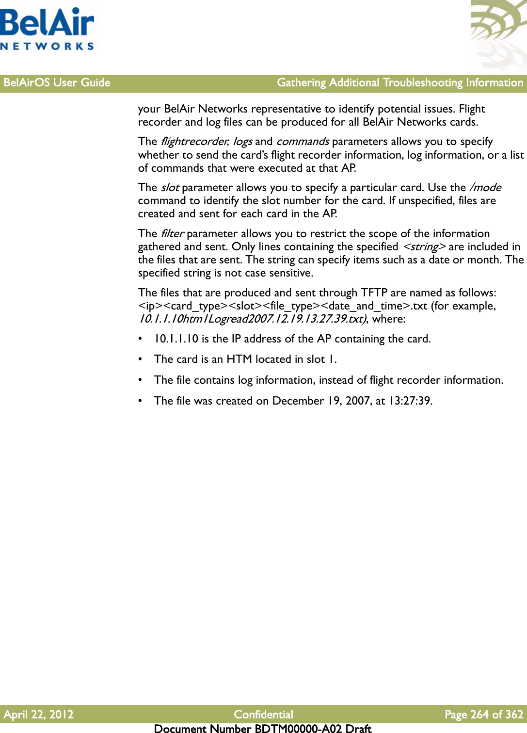
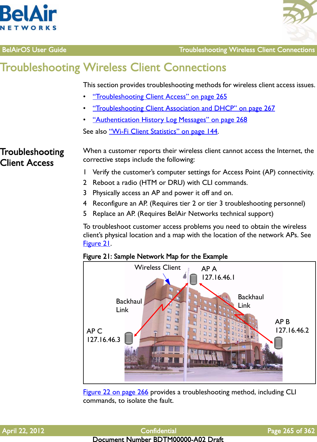
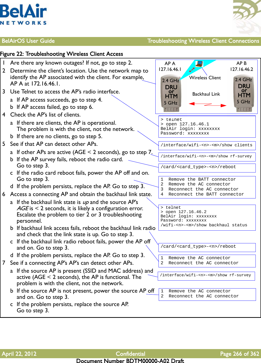
![BelAirOS User Guide Troubleshooting Wireless Client ConnectionsApril 22, 2012 Confidential Page 267 of 362Document Number BDTM00000-A02 DraftTroubleshooting Client Association and DHCPThe AP offers authentication history commands to help you troubleshoot client association or DHCP issues./interface/wifi-<n>-<m>/show authentication history [mac <mac_addr>] [ssid <ssid_index>]/interface/wifi-<n>-<m>/set authentication history filter mac {<client_mac_addr>|all}/interface/wifi-<n>-<m>/del authentication history/interface/wifi-<n>-<m>/set authentication history probes {enable|disable}These commands allow you to display authentication and DHCP log information.The displayed information includes:• a log index number• the client’s MAC address• the date and time the event occurred• log messages as described in “Authentication History Log Messages” on page 268.You can use the following to control or focus the information being displayed:• Specifying a filter in the set command restricts the recording of log messages to a specific MAC address. The default filter is FF:FF:FF:FF:FF:FF, meaning that filtering is disabled.• Enabling probes allows probe information to the displayed. By default, probe information is not shown.• Specifying a particular MAC address or SSID index in the show command restricts the display to the log events for the client with that MAC address or SSID index.Use the del parameter to clear the recorded log information from the AP.Example/interface/wifi-1-1# show authentication history mac 00:05:4E:4F:39:D8Client Authentication History - [filter: FF:FF:FF:FF:FF:FF] [probes: disabled]--------------------------------------------------------------------002 [00:05:4E:4F:39:D8] 2006-09-28 02:52:59 DHCP [192.168.219.1]->[192.168.219.1] - [request]->[ack]003 [00:05:4E:4F:39:D8] 2006-09-28 02:52:59 DHCP [192.168.219.1]->[192.168.219.1] - [offer]->[request]004 [00:05:4E:4F:39:D8] 2006-09-28 02:52:59 DHCP [0.0.0.0]->[192.168.219.1] - [discover]->[offer]005 [00:05:4E:4F:39:D8] 2006-09-28 02:52:59 DHCP [0.0.0.0]->[0.0.0.0] - [init]->[discover]006 [00:05:4E:4F:39:D8] 2006-09-28 02:52:59 <g> WPA authentication complete007 [00:05:4E:4F:39:D8] 2006-09-28 02:52:55 <r> EAP Replay counter mismatch008 [00:05:4E:4F:39:D8] 2006-09-28 02:52:53 <r> Client failing to reply to EAP packet...retrying.009 [00:05:4E:4F:39:D8] 2006-09-28 02:52:50 WPA assoc Complete](https://usermanual.wiki/Ericsson-Wi-Fi/40005011.User-Manual/User-Guide-1698497-Page-267.png)
![BelAirOS User Guide Troubleshooting Wireless Client ConnectionsApril 22, 2012 Confidential Page 268 of 362Document Number BDTM00000-A02 Draft-------------------------------end----------------------------------Authentication History Log MessagesThe following success or failure codes precede the displayed log messages:•<r>, (red), indicating a failure•<g>, (green), indicating a successful or complete association or authentication•<b>, (blue), indicating a significant non-failure event, such as the beginning of authenticationInformation events do not display a preceding success or failure code. The following sections describe the different types of events that the log messages describe:•“Normal Network Events” on page 268•“Normal Client Events” on page 269•“Network Failure Events” on page 270•“Client Failure Events” on page 270•“Client EAP Failure Events” on page 271Each section lists the actual displayed log message followed by a brief explanation.Normal Network Events RADIUS server accepted clientThis log message is generated when the RADIUS server sends the access-accept packet.DHCP [previous state]->[new state] – [previous IP]->[new IP]The DHCP exchange between the client and the DHCP server generate several log messages with this format. Refer to Table 19 for a description of the various states. Previous IP and new IP are extracted from the captured packets.Table 19: DHCP State Descriptions DHCP State DescriptionInit Initialized stateDiscover The client sent a DHCP discover packet.](https://usermanual.wiki/Ericsson-Wi-Fi/40005011.User-Manual/User-Guide-1698497-Page-268.png)
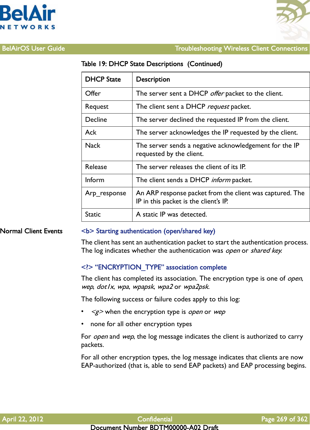
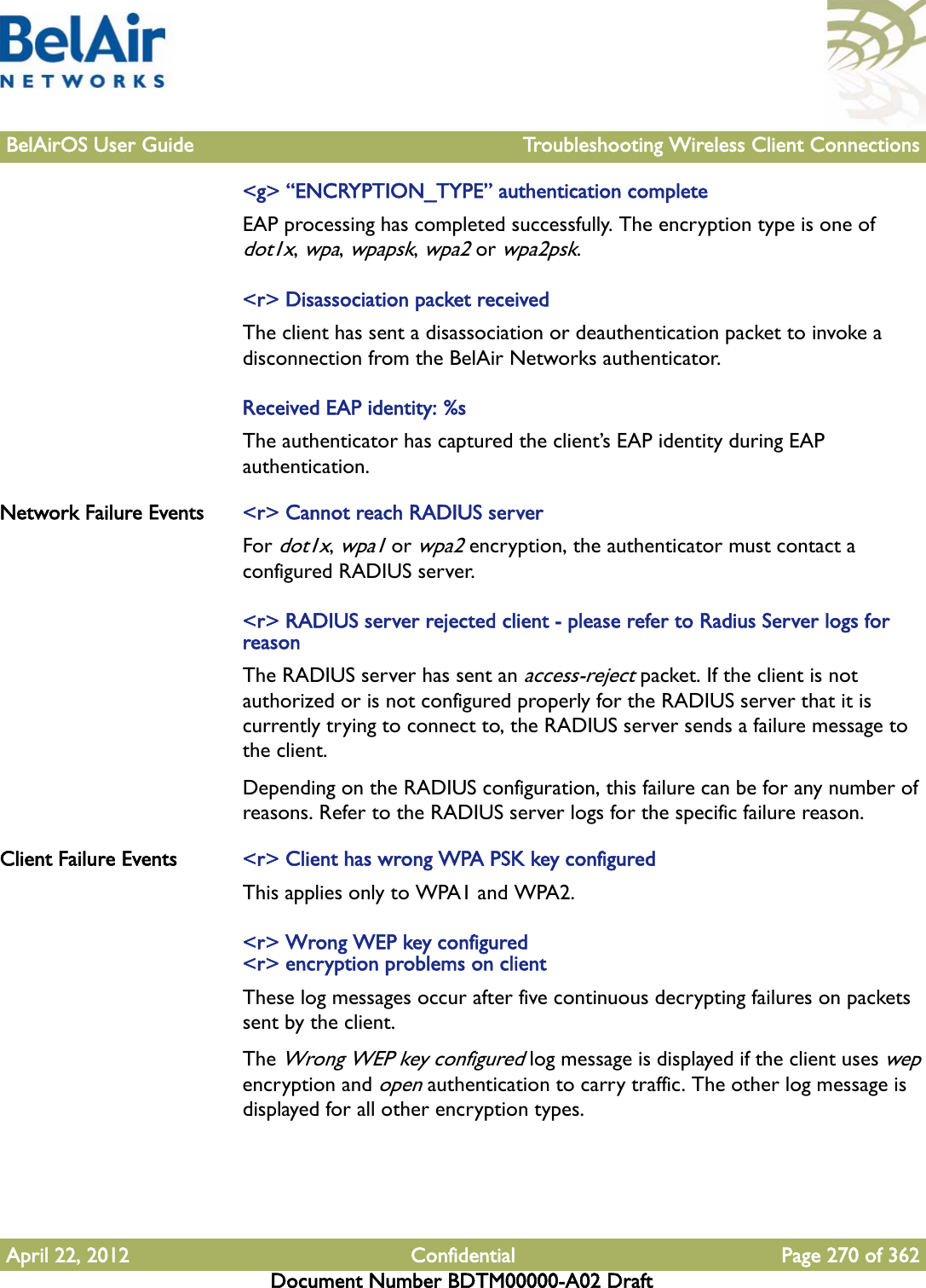
![BelAirOS User Guide Troubleshooting Wireless Client ConnectionsApril 22, 2012 Confidential Page 271 of 362Document Number BDTM00000-A02 Draft<r> denied by ACLThe client MAC address is not in the ACL.<r> does not have proper WPA or RSN IE's in assoc req<r> WPA IE does not match the advertised WPA IE<r> RSN IE does not match the advertised RSN IEThe information element in the association packet does not match the configured AP information element. For example, this can happen when the AP is configured for WPA2 and the client has selected WPA or when the client has WPA with AES selected when the SSID is configured for WPA with TKIP.Note: Not all clients reproduce this error. Some clients do not try to associate to an AP if their configured information element is different than the APs.Client EAP Failure Events <r> Client timed out while trying to connect with the RADIUS serverThe client has failed to respond to the RADIUS server packets within a 30 second interval.<r> EAP packet from client, but not EAP-enabled SSID[%d]The SSID is not configured for EAP but the client is sending EAP packets.<r> Client failing to reply to EAP packet...retryingThe EAP packet, used for dot1x, wpa1, wpa1psk, wpa2 and wpa2psk, did not reach the client or the client did not properly decrypt the packet. The authenticator retries the EAP exchange three times, then times out and restarts the entire authentication process.<r> timed out WPA1 EAP exchange<r> timed out WPA2 EAP exchangeThe client has failed to respond to the EAP packet after three retries and the EAP process restarts.<r> EAP replay counter mismatchThe EAP replay counter does not match the number of key packets sent. The EAP key contains a replay counter that increments with each EAP key packet to protect against issues with key exchange. If the counter does not match the number of key packets sent, the client restarts the EAP authentication.](https://usermanual.wiki/Ericsson-Wi-Fi/40005011.User-Manual/User-Guide-1698497-Page-271.png)
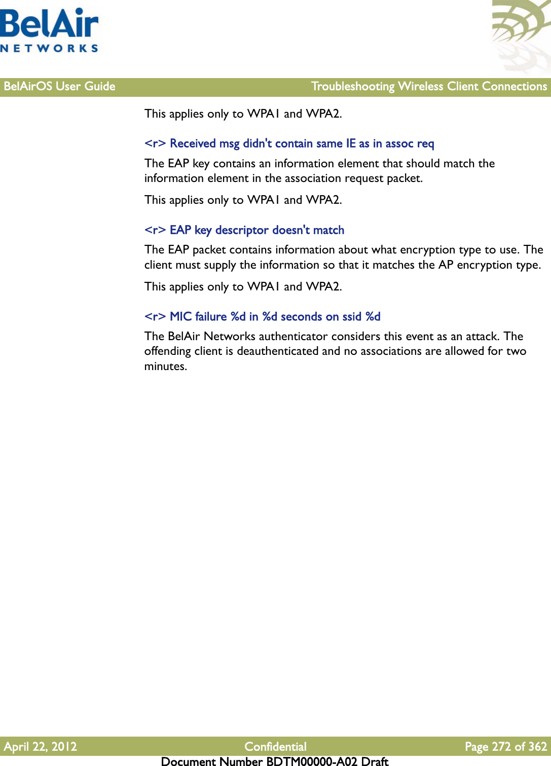
![BelAirOS User Guide Running Link DiagnosticsApril 22, 2012 Confidential Page 273 of 362Document Number BDTM00000-A02 DraftRunning Link DiagnosticsThis chapter describes tools to help you determine the relative health of your links.This chapter contains the following sections:•“Path Trace Tool” on page 273•“Traffic Tool” on page 273Path Trace Tool /diagnostics/trace path <ip_address>This command displays the number of hops between you and the supplied IP address. The trace path command only operates on BelAir Networks APs. If there is a non-BelAir Networks AP in between source AP and the destination AP, the trace result displays unreachable.Example /diagnostics# trace path 10.9.9.110PING 10.9.9.110 (10.9.9.110): 56 data bytes64 bytes from 10.9.9.110: icmp_seq=0 ttl=64 time=37.7 ms64 bytes from 10.9.9.110: icmp_seq=1 ttl=64 time=17.1 ms64 bytes from 10.9.9.110: icmp_seq=2 ttl=64 time=11.3 ms--- 10.9.9.110 ping statistics ---3 packets transmitted, 3 packets received, 0% packet loss round-trip min/avg/max = 11.3/22.0/37.7 mshop 1: IP 10.9.9.201hop 2: IP 10.9.9.200hop 3: IP 10.9.9.51hop 4: IP 10.9.9.110Tra ffic To ol /diagnostics/test link IP <ip_addr> rate-kbps <num_str> { hop-by-hop | end-to-end } [update_interval <num_str>] [duration <num_str>] [dir {rx|tx|both}] [ip_scope <ip_addr>]/diagnostics/stop {all | session <session_id> ip_scope <ip_addr>}/diagnostics/show statusThis command first runs a path trace and then runs traffic between you and a supplied IP address.](https://usermanual.wiki/Ericsson-Wi-Fi/40005011.User-Manual/User-Guide-1698497-Page-273.png)
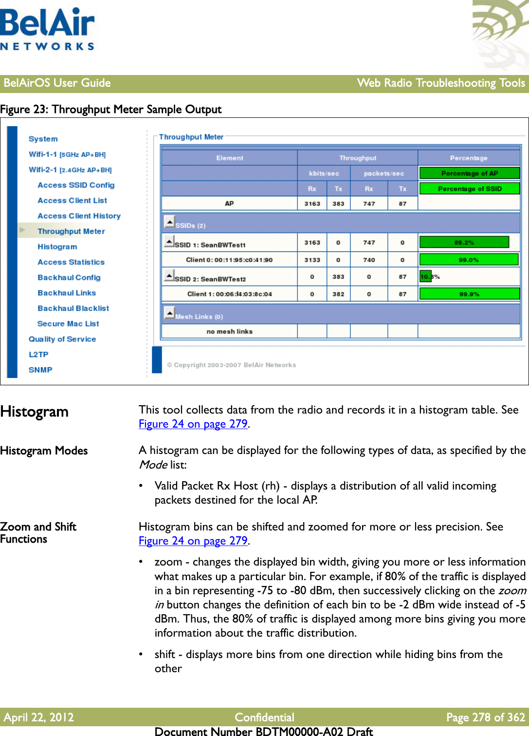
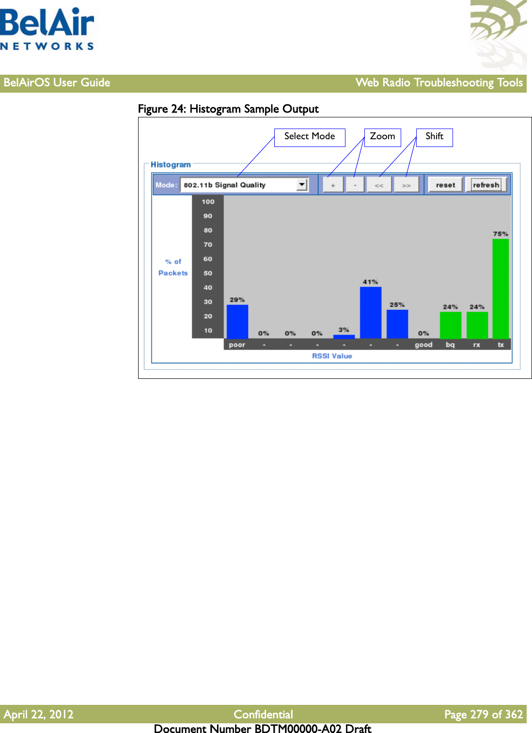
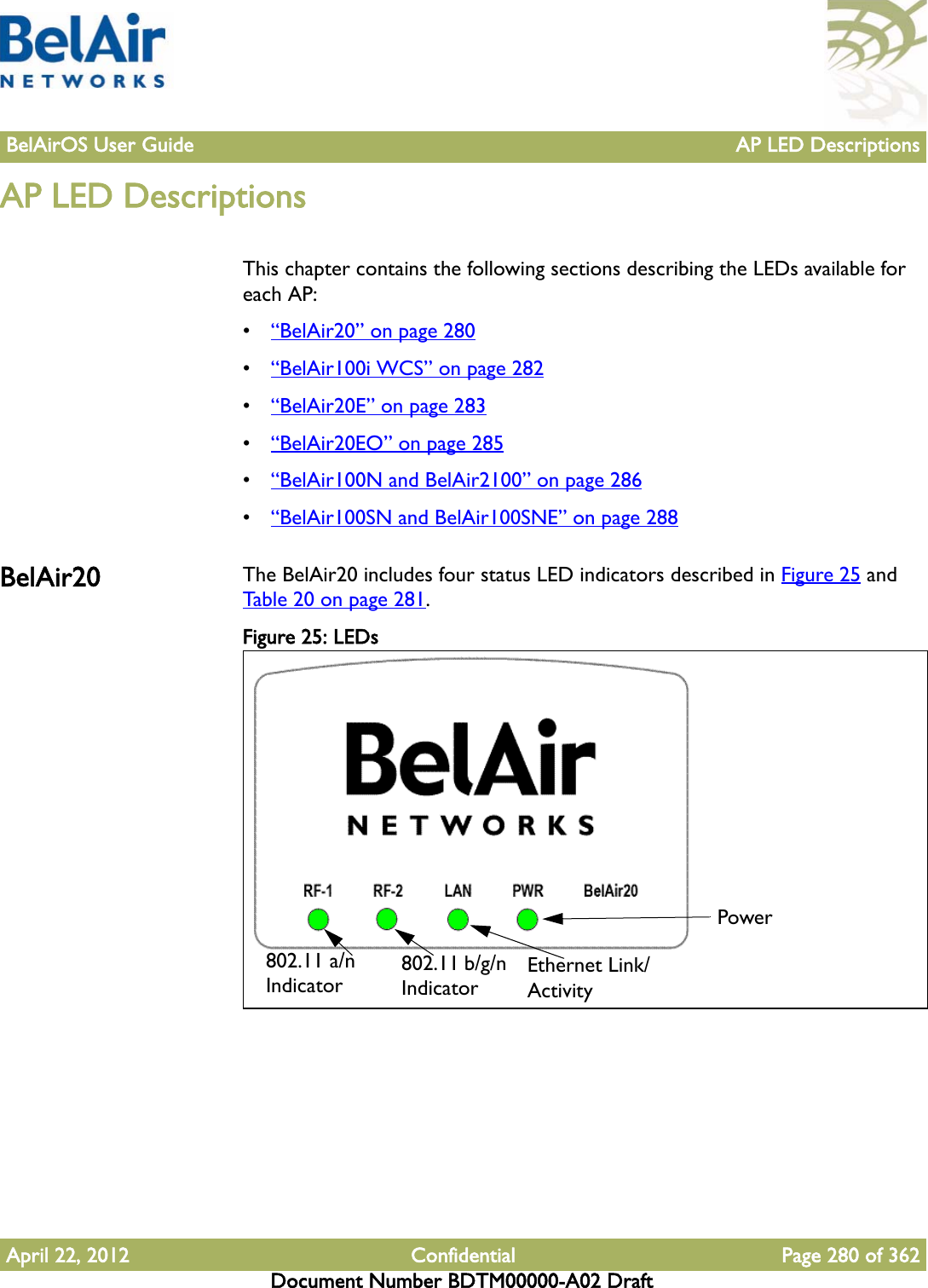
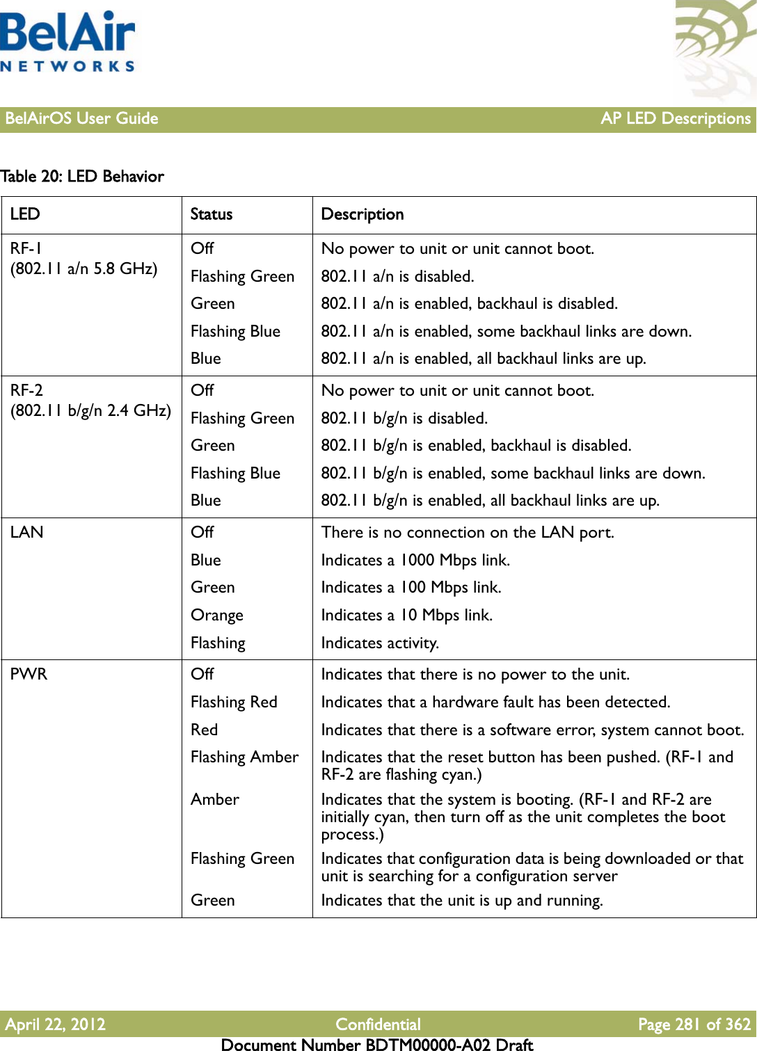
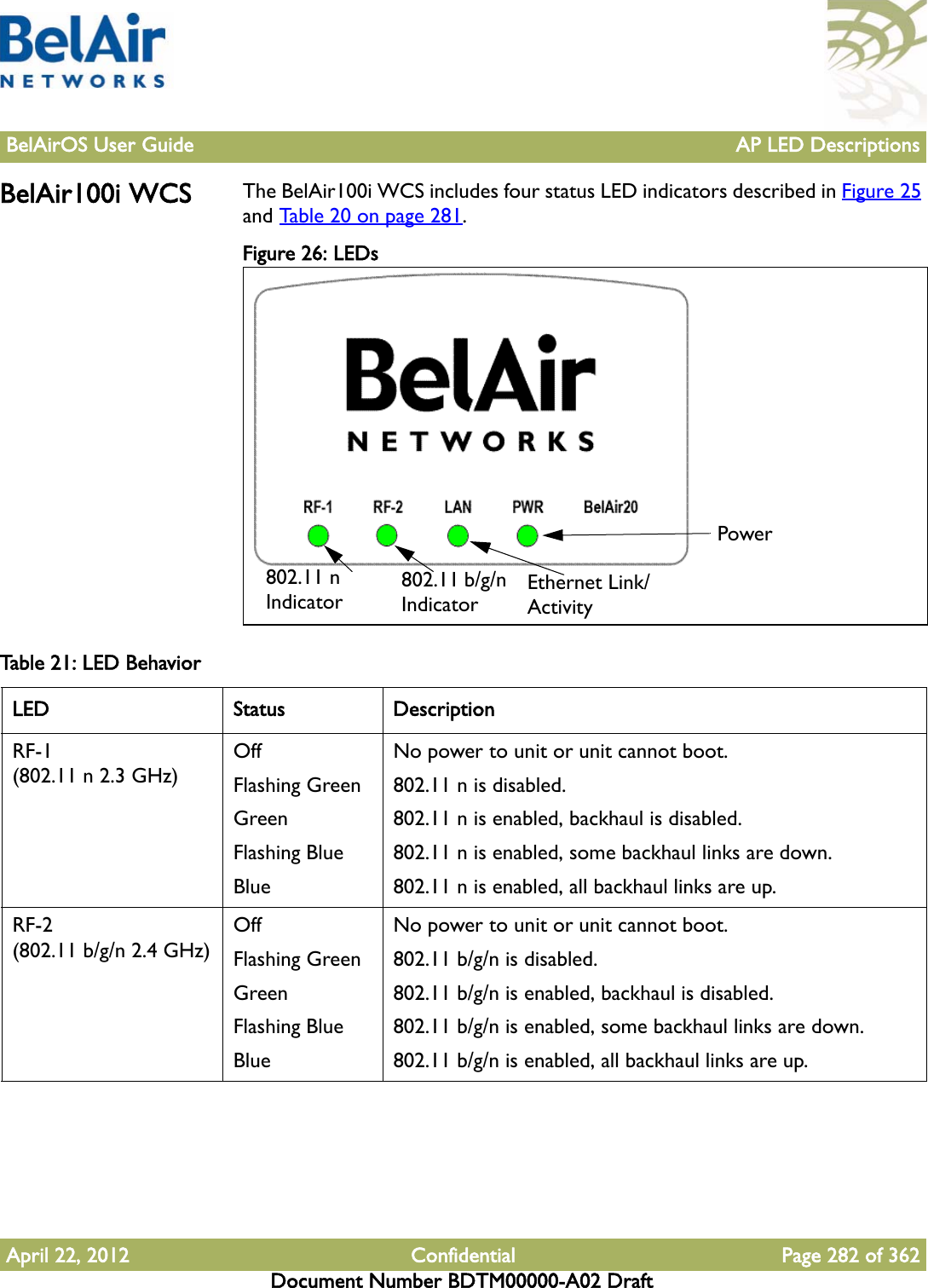
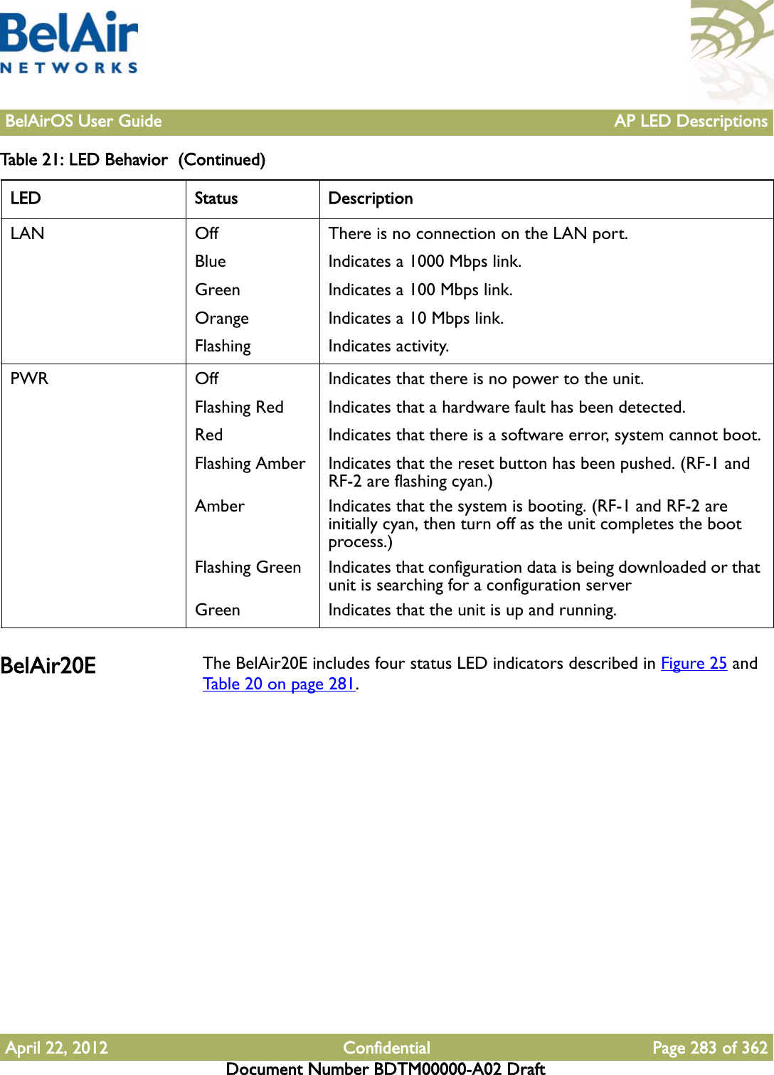
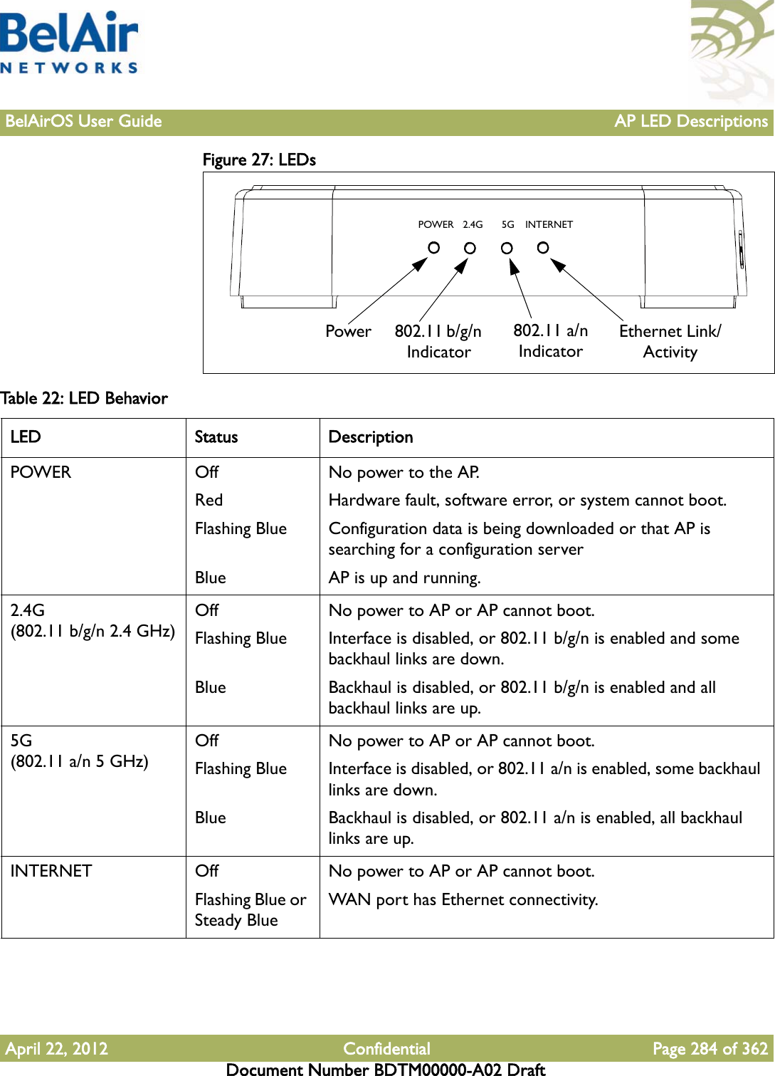
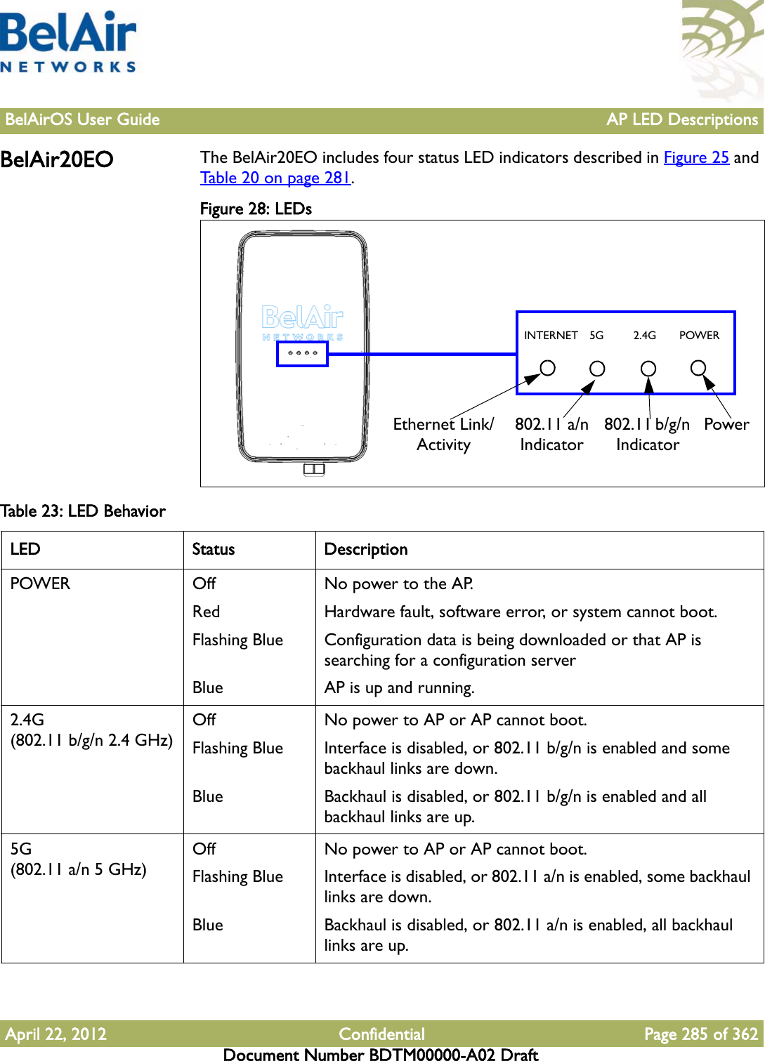
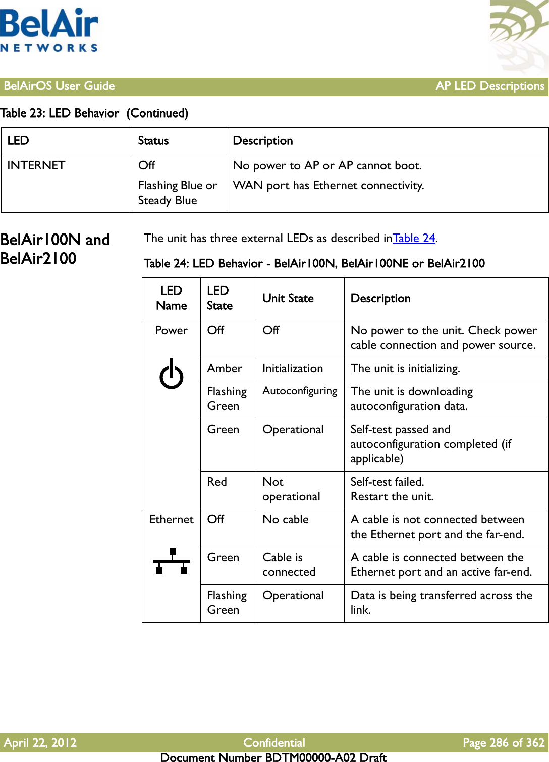
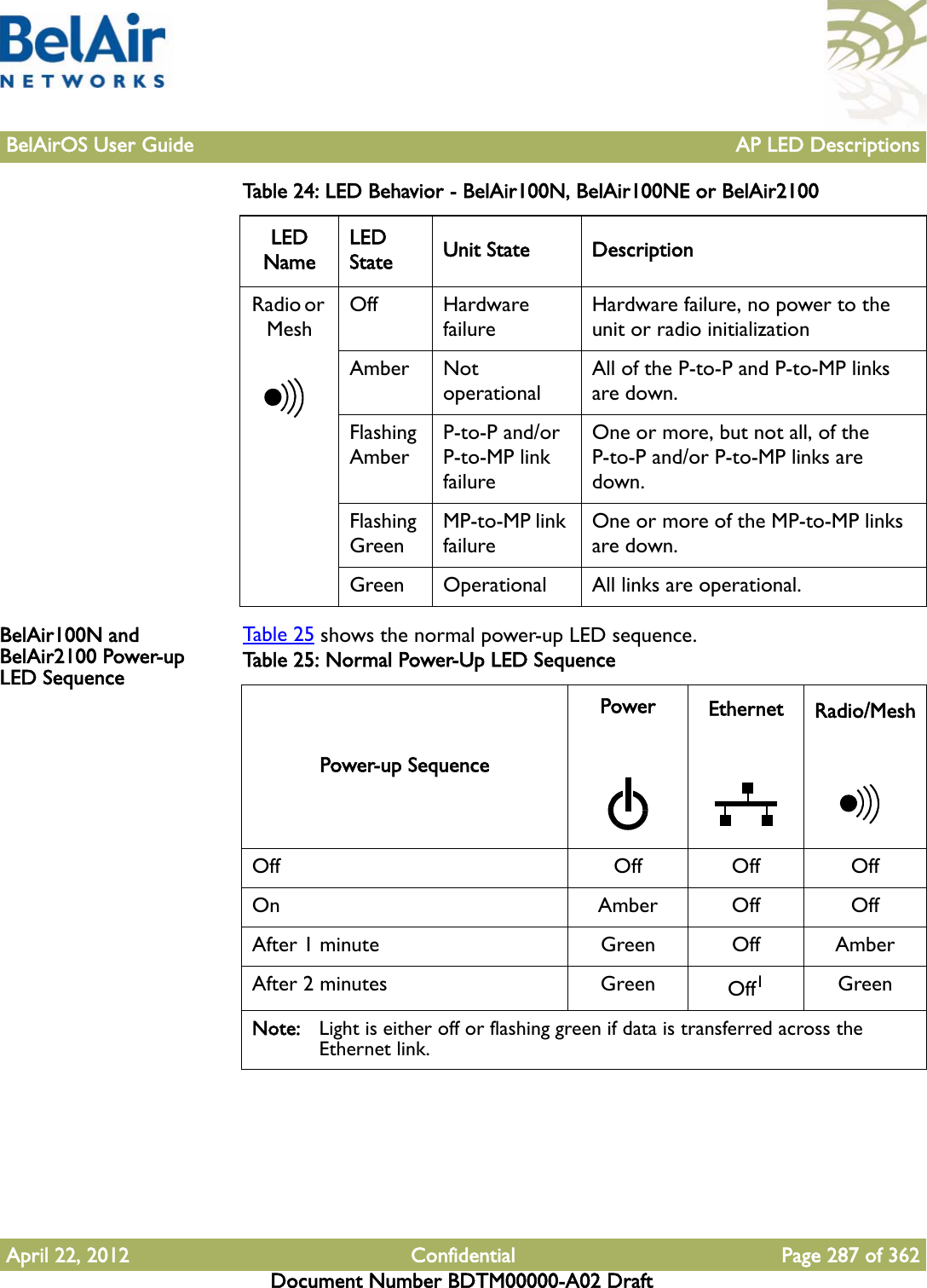
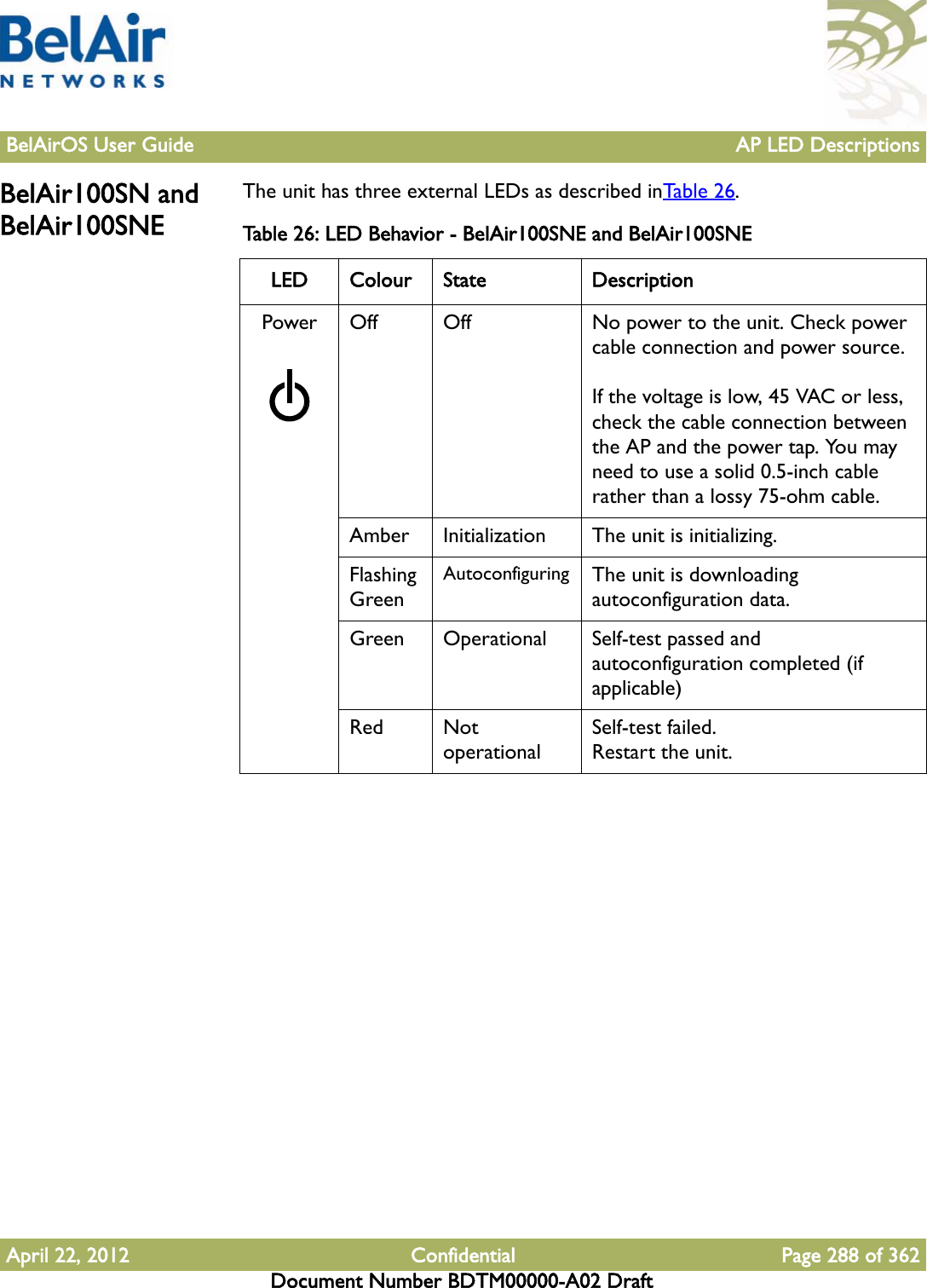
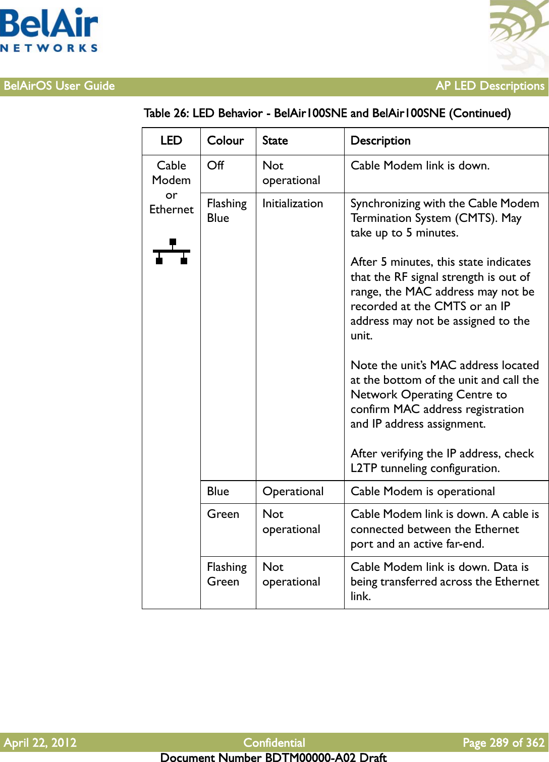
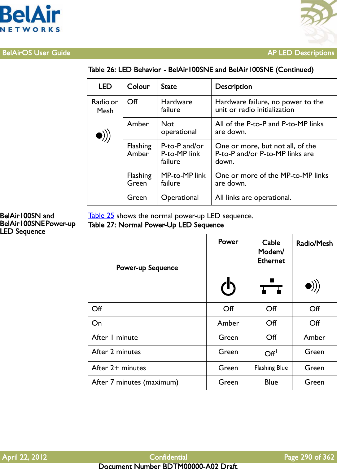
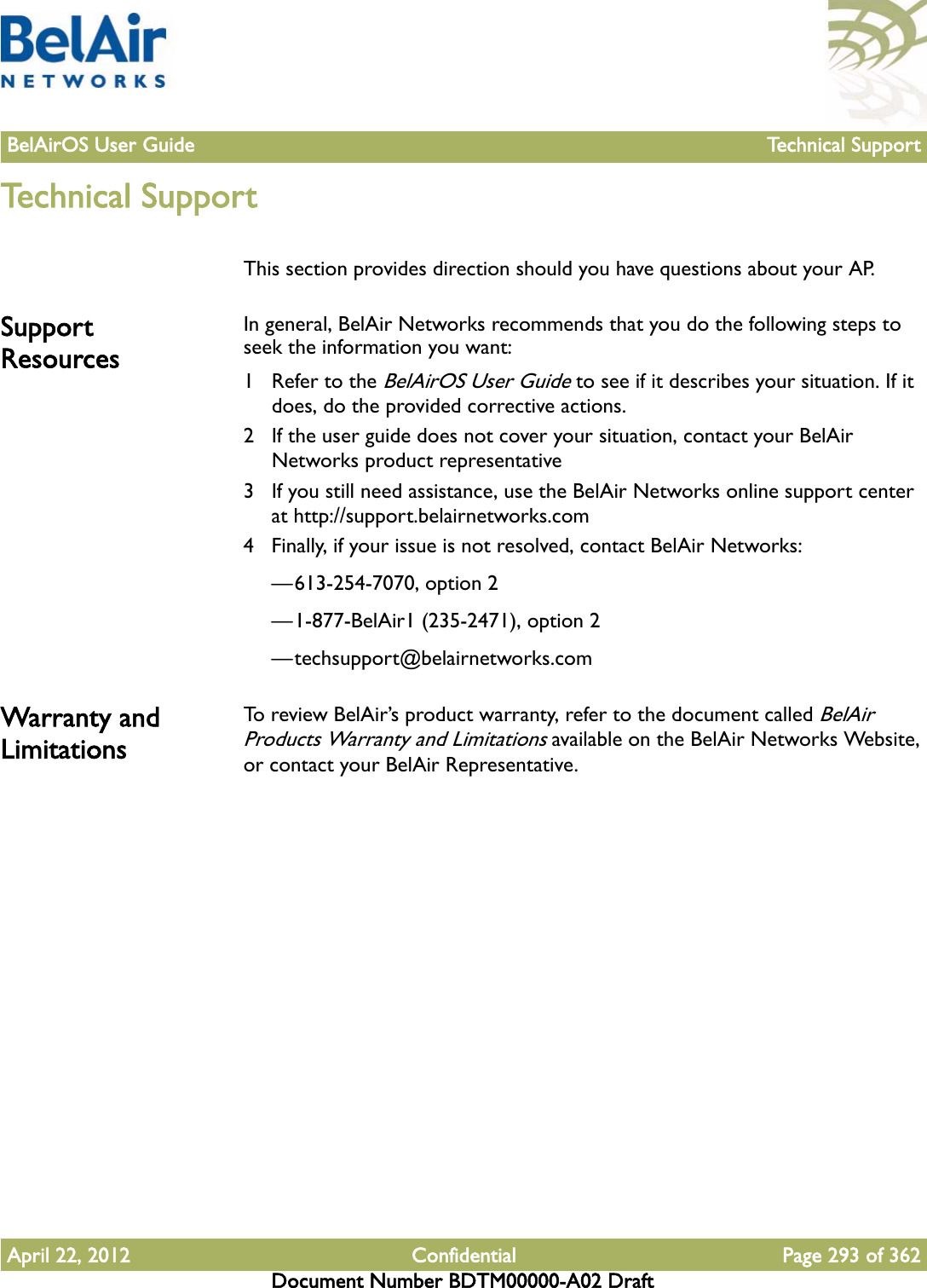
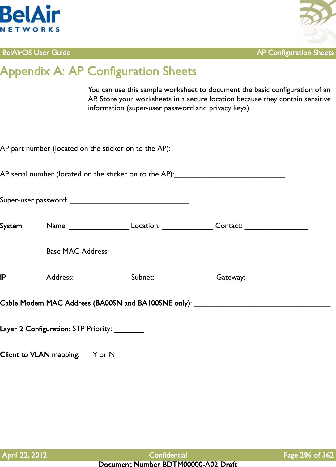
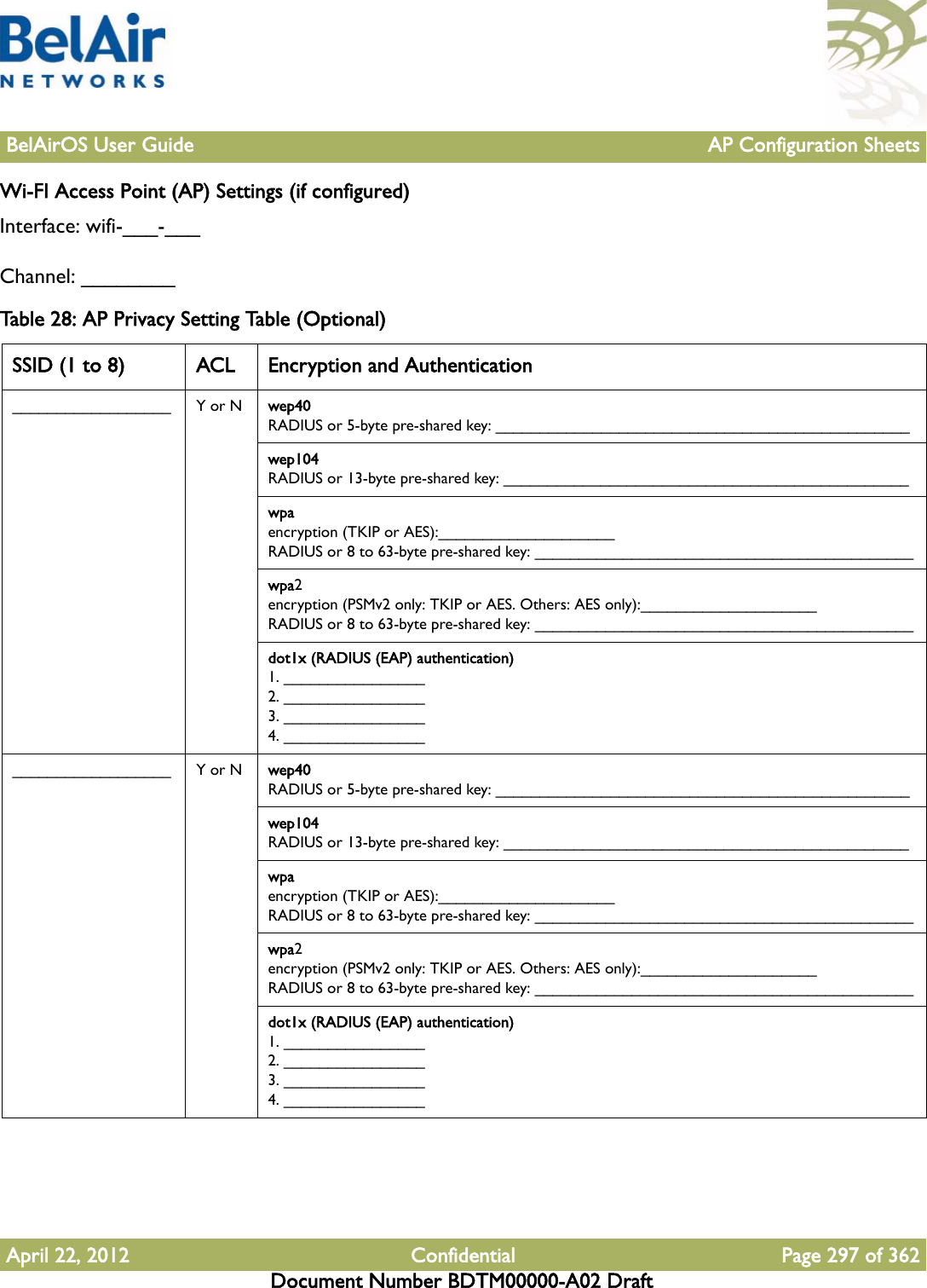
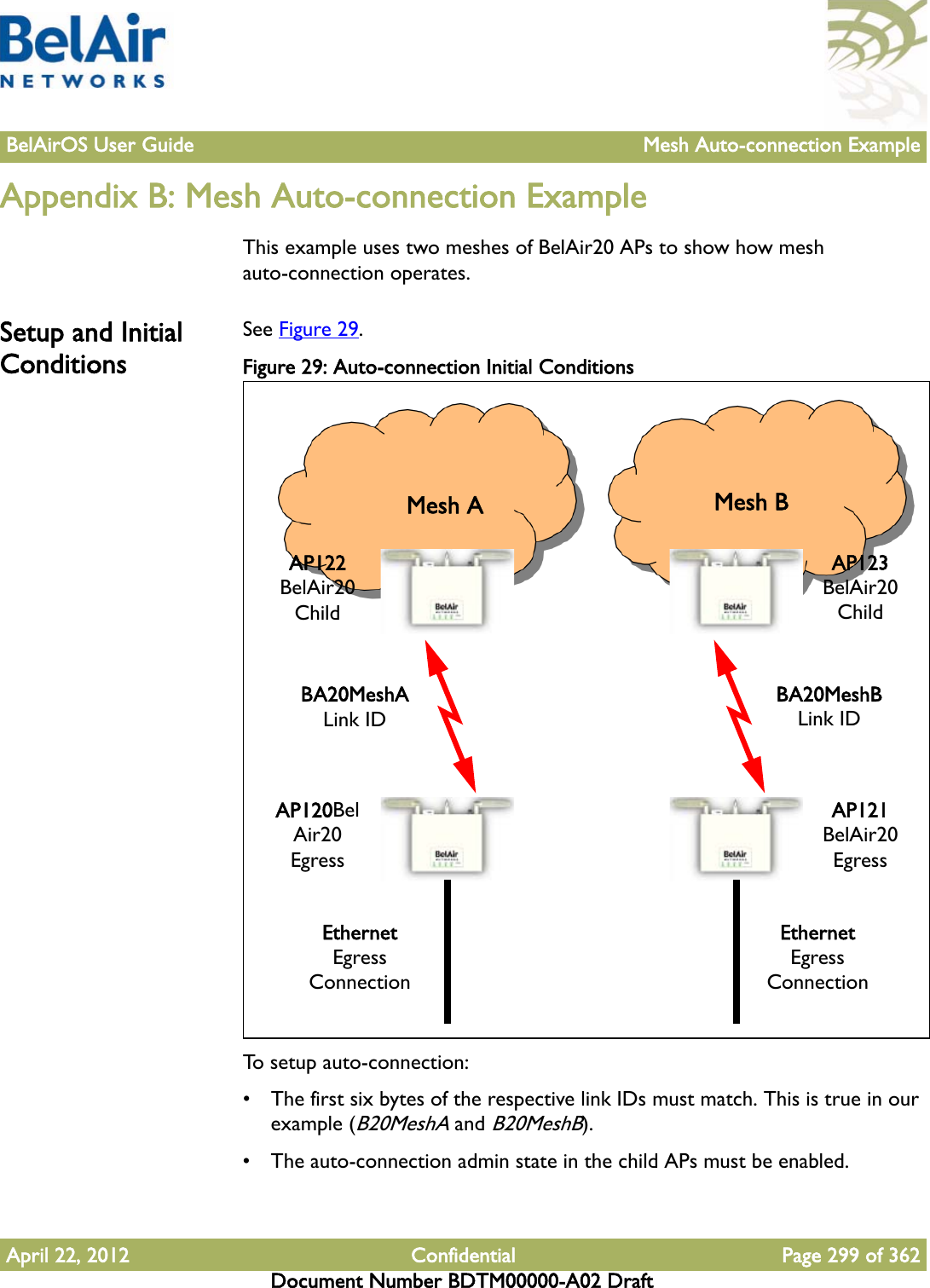
![BelAirOS User Guide Mesh Auto-connection ExampleApril 22, 2012 Confidential Page 300 of 362Document Number BDTM00000-A02 Draft• The egress AP of each mesh must have its system egress point set to either yes direct or yes indirect. See “Setting the Network Egress Point” on page 72 for details.The following series of CLI commands show this for both meshes.AP122 (Child AP of Mesh A)Display the backhaul configuration./interface/wifi-1-1# show config backhaulSlot: 1, Card Type: htm, revision: 1, Port: 1, Radio: HTMv1 5GHz 802.11nadmin state: ................. Enabledchannel: ..................... 161 mode: ...................... ht20 mimo: ...................... 3x3 tx power: .................. 18.0 (dBm per-chain), 23.0 (dBm total)antenna gain: ................ 5.0 (dBi)link distance: ............... 1 (km)tx aggregation:............... Enabledbase radio MAC : ............. 00:0d:67:10:e8:92Backhaul: Common: privacy: ................. Disabled mesh-min-rssi............. -100 (dbm) Stationary Backhaul: link admin state: ........ Enabled link id: ................. B20MeshA topology: ................ mesh Mobile Backhaul: mobile admin state: ...... Disabled mobile link id: .......... mobile link role: ........ ss Protection Backhaul: protection admin state: .. DisabledBlacklist: No blacklist entriesLink Failure Detection: ...... DisabledBackhaul T1 Bandwidth limit:.. DisabledDisplay the mesh topology./interface/wifi-1-1# show backhaul statusWiFi backhaul states:: stationary=[Enabled] mobile=[Disabled] protection=[Disabled]Backhaul Links: Link Radio Mac State(L,R) RSSI Radio Node IP Node Name ----- ----------------- ---------- ---- ----- -------- ---------- [S] 1 00:0d:67:0c:22:4b fwd fwd -46 wifi-1-1 180.7.4.120](https://usermanual.wiki/Ericsson-Wi-Fi/40005011.User-Manual/User-Guide-1698497-Page-300.png)
![BelAirOS User Guide Mesh Auto-connection ExampleApril 22, 2012 Confidential Page 301 of 362Document Number BDTM00000-A02 DraftEnable auto-connection and verify it./services/auto-conn# set admin enabled/services/auto-conn# show configadmin state: ................. Enabled/services/auto-conn# show statusOper State Ether Link State Egress Reachable Use Alternate Mesh----------- ---------- ---------------- ----------------up down no noAP120 (Egress AP of Mesh A)Display the mesh topology./interface/wifi-1-1# show backhaul statusWiFi backhaul states:: stationary=[Enabled] mobile=[Disabled] protection=[Disabled]Backhaul Links: Link Radio Mac State(L,R) RSSI Radio Node IP Node Name ----- ----------------- ---------- ---- ----- -------- ---------- [S] 1 00:0d:67:10:e8:92 fwd fwd -44 wifi-1-1 180.7.4.122Identify AP120 as an egress AP./system# set system-egress-point yes direct/system# show system-egress-pointegress point:................. directEnable auto-connection and verify it./services/auto-conn# set admin enable/services/auto-conn# show configadmin state: ................. Enabled/services/auto-conn# show statusOper State Ether Link State Egress Reachable Use Alternate Mesh----------- ---------- ---------------- ----------------up up yes noAP123 (Child AP of Mesh B)Display the backhaul configuration./interface/wifi-1-1# show config backhaulSlot: 1, Card Type: htm, revision: 1, Port: 1, Radio: HTMv1 5GHz 802.11nadmin state: ................. Enabledchannel: ..................... 153 mimo: ...................... 1x1 tx power: .................. 18.0 (dBm per-chain), 18.0 (dBm total)antenna gain: ................ 5.0 (dBi)link distance: ............... 1 (km)tx aggregation:............... Enabledbase radio MAC : ............. 00:0d:67:10:f8:d7Backhaul:](https://usermanual.wiki/Ericsson-Wi-Fi/40005011.User-Manual/User-Guide-1698497-Page-301.png)
![BelAirOS User Guide Mesh Auto-connection ExampleApril 22, 2012 Confidential Page 302 of 362Document Number BDTM00000-A02 Draft Common: privacy: ................. Disabled mesh-min-rssi............. -100 (dbm) Stationary Backhaul: link admin state: ........ Enabled link id: ................. B20MeshB topology: ................ mesh Mobile Backhaul: mobile admin state: ...... Disabled mobile link id: .......... mobile link role: ........ ss Protection Backhaul: protection admin state: .. DisabledBlacklist: No blacklist entriesLink Failure Detection: ...... DisabledBackhaul T1 Bandwidth limit:.. DisabledDisplay the mesh topology./interface/wifi-1-1# show backhaul statusWiFi backhaul states:: stationary=[Enabled] mobile=[Disabled] protection=[Disabled]Backhaul Links: Link Radio Mac State(L,R) RSSI Radio Node IP Node Name ----- ----------------- ---------- ---- ----- -------- ---------- [S] 1 00:0d:67:0c:22:29 fwd fwd -49 wifi-1-1 180.7.4.121Enable auto-connection and verify it./services/auto-conn# set admin enabled/services/auto-conn# show configadmin state: ................. Enabled/services/auto-conn# show statusOper State Ether Link State Egress Reachable Use Alternate Mesh----------- ---------- ---------------- ----------------up down no noAP121 (Egress AP of Mesh B)Display the mesh topology./interface/wifi-1-1# show backhaul statusWiFi backhaul states:: stationary=[Enabled] mobile=[Disabled] protection=[Disabled]Backhaul Links: Link Radio Mac State(L,R) RSSI Radio Node IP Node Name ----- ----------------- ---------- ---- ----- -------- ---------- [S] 1 00:0d:67:10:f8:d7 fwd fwd -41 wifi-1-1 180.7.4.123](https://usermanual.wiki/Ericsson-Wi-Fi/40005011.User-Manual/User-Guide-1698497-Page-302.png)
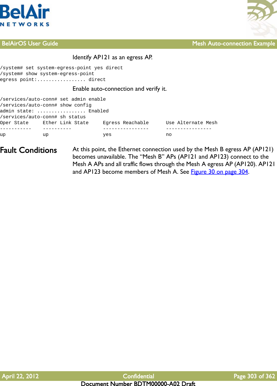
![BelAirOS User Guide Mesh Auto-connection ExampleApril 22, 2012 Confidential Page 304 of 362Document Number BDTM00000-A02 DraftFigure 30: Auto-connection and Fault ConditionsAP120 (Egress AP of Mesh A)Display the mesh topology./interface/wifi-1-1# show backhaul statusWiFi backhaul states:: stationary=[Enabled] mobile=[Disabled] protection=[Disabled]Backhaul Links: Link Radio Mac State(L,R) RSSI Radio Node IP Node Name ----- ----------------- ---------- ---- ----- -------- ---------- [S] 1 00:0d:67:10:e8:92 fwd up -46 wifi-1-1 180.7.4.122 [S] 2 00:0d:67:0c:22:29 fwd fwd -36 wifi-1-1 180.7.4.121 [S] 3 00:0d:67:10:f8:d7 fwd up -64 wifi-1-1 180.7.4.123AP123 BelAir20ChildAP121 BelAir20EgressBA20MeshBLink IDEthernetEgress ConnectionAP122 BelAir20ChildAP120BelAir20EgressBA20MeshALink IDEthernetEgress ConnectionMesh A Mesh B](https://usermanual.wiki/Ericsson-Wi-Fi/40005011.User-Manual/User-Guide-1698497-Page-304.png)
![BelAirOS User Guide Mesh Auto-connection ExampleApril 22, 2012 Confidential Page 305 of 362Document Number BDTM00000-A02 DraftDisplay the auto-connect topology. It shows that the Mesh A egress AP still operates normally./services/auto-conn# show statusOper State Ether Link State Egress Reachable Use Alternate Mesh----------- ---------- ---------------- ----------------up up yes noAP122 (Child AP of Mesh A)Display the mesh topology./interface/wifi-1-1# show backhaul statusWiFi backhaul states:: stationary=[Enabled] mobile=[Disabled] protection=[Disabled]Backhaul Links: Link Radio Mac State(L,R) RSSI Radio Node IP Node Name ----- ----------------- ---------- ---- ----- -------- ---------- [S] 1 00:0d:67:0c:22:4b up fwd -51 wifi-1-1 180.7.4.120 [S] 2 00:0d:67:0c:22:29 fwd fwd -41 wifi-1-1 180.7.4.121 [S] 3 00:0d:67:10:f8:d7 fwd up -58 wifi-1-1 180.7.4.123Display the auto-connect topology. /services/auto-conn# show statusOper State Ether Link State Egress Reachable Use Alternate Mesh----------- ---------- ---------------- ----------------up down yes noAP123 (Child AP of Mesh B)Display the backhaul configuration./interface/wifi-1-1# show config backhaulSlot: 1, Card Type: htm, revision: 1, Port: 1, Radio: HTMv1 5GHz 802.11nadmin state: ................. Enabledchannel: ..................... 153 mimo: ...................... 1x1 tx power: .................. 18.0 (dBm per-chain), 18.0 (dBm total)antenna gain: ................ 5.0 (dBi)link distance: ............... 1 (km)tx aggregation:............... Enabledbase radio MAC : ............. 00:0d:67:10:f8:d7Backhaul: Common: privacy: ................. Disabled mesh-min-rssi............. -100 (dbm) Stationary Backhaul: link admin state: ........ Enabled link id: ................. B20MeshB topology: ................ mesh Mobile Backhaul:](https://usermanual.wiki/Ericsson-Wi-Fi/40005011.User-Manual/User-Guide-1698497-Page-305.png)
![BelAirOS User Guide Mesh Auto-connection ExampleApril 22, 2012 Confidential Page 306 of 362Document Number BDTM00000-A02 Draft mobile admin state: ...... Disabled mobile link id: .......... mobile link role: ........ ss Protection Backhaul: protection admin state: .. DisabledBlacklist: No blacklist entriesLink Failure Detection: ...... DisabledBackhaul T1 Bandwidth limit:.. DisabledDisplay the mesh topology./interface/wifi-1-1# show backhaul statusWiFi backhaul states:: stationary=[Enabled] mobile=[Disabled] protection=[Disabled]Backhaul Links: Link Radio Mac State(L,R) RSSI Radio Node IP Node Name ----- ----------------- ---------- ---- ----- -------- ---------- [S] 1 00:0d:67:10:e8:92 up fwd -58 wifi-1-1 180.7.4.122 [S] 2 00:0d:67:0c:22:29 fwd fwd -47 wifi-1-1 180.7.4.121 [S] 3 00:0d:67:0c:22:4b up fwd -67 wifi-1-1 180.7.4.120Display the auto-connect topology. /services/auto-conn# show statusOper State Ether Link State Egress Reachable Use Alternate Mesh----------- ---------- ---------------- ----------------up down yes yesAP121 (Egress AP of Mesh B)Display the auto-connect topology. It shows that it is using the alternate mesh as an egress point./services/auto-conn# show statusOper State Ether Link State Egress Reachable Use Alternate Mesh----------- ---------- ---------------- ----------------up down yes yesRecovery ConditionsAt this point, the Ethernet connection used by the Mesh B egress AP (AP121) is re-established. Because it is an egress AP, AP121 automatically reverts back to its own mesh and begins to use the Ethernet connection to egress its traffic. However, its child APs (for example, AP123) continue to use the Mesh A egress AP until an explicit revert command is issued on each child you want to return to using AP121 as an egress.](https://usermanual.wiki/Ericsson-Wi-Fi/40005011.User-Manual/User-Guide-1698497-Page-306.png)
![BelAirOS User Guide Mesh Auto-connection ExampleApril 22, 2012 Confidential Page 307 of 362Document Number BDTM00000-A02 DraftAP121 (Egress AP of Mesh B)Display the auto-connect topology after the Ethernet connection is re-established. /services/auto-conn# show statusOper State Ether Link State Egress Reachable Use Alternate Mesh----------- ---------- ---------------- ----------------up up yes noDisplay the AP’s links to neighboring mesh, even after the Ethernet connection is re-established. /services/auto-conn# show alternate-meshAlternate Mesh: Radio Interface --- wifi-1-1 Mesh ID --- B20MeshA Channel --- 161 Status --- UpAP122 (Child AP of Mesh A)Display the mesh topology after the Ethernet connection is re-established on AP121 but before the auto-connection revert command is given./interface/wifi-1-1# show backhaul statusWiFi backhaul states:: stationary=[Enabled] mobile=[Disabled] protection=[Disabled]Backhaul Links: Link Radio Mac State(L,R) RSSI Radio Node IP Node Name ----- ----------------- ---------- ---- ----- -------- ---------- [S] 1 00:0d:67:0c:22:4b fwd fwd -49 wifi-1-1 180.7.4.120 [S] 3 00:0d:67:10:f8:d7 fwd fwd -58 wifi-1-1 180.7.4.123See Figure 31 on page 308.](https://usermanual.wiki/Ericsson-Wi-Fi/40005011.User-Manual/User-Guide-1698497-Page-307.png)
![BelAirOS User Guide Mesh Auto-connection ExampleApril 22, 2012 Confidential Page 308 of 362Document Number BDTM00000-A02 DraftFigure 31: Auto-connection after Recovery before RevertDisplay the mesh topology after the Ethernet connection is re-established on AP121 and after the auto-connection revert command is given./interface/wifi-1-1# show backhaul statusWiFi backhaul states:: stationary=[Enabled] mobile=[Disabled] protection=[Disabled]Backhaul Links: Link Radio Mac State(L,R) RSSI Radio Node IP Node Name ----- ----------------- ---------- ---- ----- -------- ---------- [S] 1 00:0d:67:0c:22:4b fwd fwd -49 wifi-1-1 180.7.4.120After the revert command is given, the mesh topology returns to that shown in Figure 29 on page 299.AP123 BelAir20ChildAP121 BelAir20EgressBA20MeshBLink IDEthernetEgress ConnectionAP122 BelAir20ChildAP120BelAir20EgressBA20MeshALink IDEthernetEgress ConnectionMesh A Mesh B](https://usermanual.wiki/Ericsson-Wi-Fi/40005011.User-Manual/User-Guide-1698497-Page-308.png)
![BelAirOS User Guide Scripting GuidelinesApril 22, 2012 Confidential Page 310 of 362Document Number BDTM00000-A02 Draftthen your script must include special declarations. For details, see “Including a Reboot Command in a Script” on page 316.Caution! Using the reboot command in an auto-configuration script without the correct declarations may cause the AP to enter a continuous reboot loop.• Test the final script to ensure all commands are valid, syntactically correct and appropriate for the installed hardware. To help debugging, redirect the output of the script to a file. Use the optional <output_file> parameter of the run script command. When you are satisfied with your script:1 Put the final version of it on a TFTP, FTP or FTPS server to transfer the script file to the AP.2 Use the commands described in “Manually Transferring Files to and from an AP” on page 310 to transfer the script to the APs you want to control.3 Use the commands described in “Managing and Manually Running Script Files” on page 311 as required.The process of downloading and running a script file on startup can be automated. For details, see the “AP Auto-configuration” on page 78. Manually Transferring Files to and from an AP Use the following CLI commands to manually transfer files, such as script files, to and from an AP:/system/tftpget remoteip <ip_addr> remotefile <filename> [localfile <filename>]/system/tftpput remoteip <ip_addr> localfile <filename> [remotefile <name>]/system/getfile remoteip <ip_addr> remotefile <filename> [localfile <filename>] [{tftp| ftp [user <username> password <password>]| ftps [user <username> password <password>]}]For the tftpget and getfile commands, if you do not specify a local file name, then the transferred file maintains the same name as on the remote file system.For the tftpput command, if you do not specify a remote file name, then the transferred file maintains the same name as on the local file system.For the getfile command:• The default protocol is TFTP.• For FTP, the default user name is anonymous and the default password is root@ followed by the AP IP address. For example, if the AP has 148.16.4.123 as an IP address, then the default password is root@148.16.4.123.](https://usermanual.wiki/Ericsson-Wi-Fi/40005011.User-Manual/User-Guide-1698497-Page-310.png)
![BelAirOS User Guide Scripting GuidelinesApril 22, 2012 Confidential Page 311 of 362Document Number BDTM00000-A02 Draft• For FTPS, the default user name is the AP’s MAC address stripped of colons. The default password is AP’s MAC address stripped of colons, followed by @, followed by the AP IP address. For example, if the AP has 11:22:33:44:55:66 as a MAC address and 148.16.4.123 as an IP address, then the default user name is 112233445566 and the default password is 112233445566@148.16.4.123.CAUTION! Do not use these commands to perform a software upgrade on an AP. Use the upgrade load command instead. Refer to “Performing a Software Upgrade” on page 246 for full details on performing software upgrades.Managing and Manually Running Script Files Use the following commands as required:/system/copy script <script file> <copied file name>/system/delete script <script file>/system/rename script <script file> <new name>/system/show script <script file>list scriptsrun script <scriptname> [<output_file>]The copy, delete, rename and show script commands are available in system mode and allow you to manage and customize script files as you require.The list and run script commands are available from any mode. The list scripts command displays the scripts that are available to you. The run script command allows you to execute a previously created script file.TipIf you have a simple script that does not specify physical interfaces and does not contain a reboot command, you can also run it by copying it and pasting it into a CLI session window. If you use this method:1 Paste only 20 to 25 commands at a time. Otherwise, you may overfill the command buffer used for the CLI session. If you overfill the command buffer, you need to determine exactly which commands were executed and which were not before proceeding.2 After pasting a block of commands, verify that your script behaved as expected; that is, that the pasted commands produced the expected configuration.3 After verifying the script behavior, manually enter the config-save and reboot commands as required.](https://usermanual.wiki/Ericsson-Wi-Fi/40005011.User-Manual/User-Guide-1698497-Page-311.png)
![BelAirOS User Guide Scripting GuidelinesApril 22, 2012 Confidential Page 312 of 362Document Number BDTM00000-A02 DraftSpecifying Physical InterfacesIf you want your script file to specify and control physical interfaces, such as wifi-1-1, then your script must contain the declarations described in the following sections:•“Physical Interface Declaration Summary” on page 312•“Physical Interface Declaration Specifications” on page 312As well, this chapter contains examples of the setup, contents and results of a typical script.Physical Interface Declaration Summary Table 29 summarizes the declarations required in your script file to specify a physical interface.Physical Interface Declaration SpecificationsScript files can use the following method to ensure commands are applied to the correct physical interface:1 Begin the command sequence by specifying the physical interface with the following declaration:int[-<asbly>]-<iftype>[-<desc>]-<instance>Table 29: BelAir Networks Script Declaration Summary Script Declaration Descriptionint[-<asbly>]-<iftype>[-<desc>]-<instance> Used to define a physical interface to which the following CLI commands apply to.For a definition of <asbly>, <iftype>, <desc>, and <instance>, see “Physical Interface Declaration Specifications” on page 312./Precedes a CLI command that is not directed to the specified physical interface. The CLI command must start with a slash (/) followed by the mode(s) containing that command. For details, see “Physical Interface Declaration Specifications” on page 312.int-stop Terminates a command sequence associated with a previous declaration](https://usermanual.wiki/Ericsson-Wi-Fi/40005011.User-Manual/User-Guide-1698497-Page-312.png)
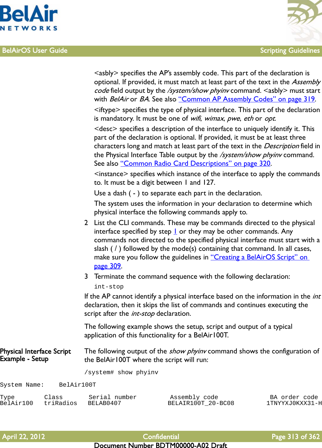
![BelAirOS User Guide Scripting GuidelinesApril 22, 2012 Confidential Page 314 of 362Document Number BDTM00000-A02 DraftPhysical Inventory TableSlot Card type Version Serial number Assembly code 1 LPM 2.2.8 K002092633 B2CH082AA-B B08 2 BRM 3.2.1 K001362023 B2CC033AA-B B01 3 BRM 3.2.1 A000003408 B2CC033AA-B B01 Physical Interface TableName Type Slot Card type Descriptionwifi-1-1 Wifi 802.11 1 LPM LPMv2 4.9GHz 802.11aeth-1-1 Ethernet 1 LPM 1x100baseTx [Electrical: Single]wifi-2-1 Wifi 802.11 2 BRM BRMv3 5GHz 802.11awifi-3-1 Wifi 802.11 3 BRM BRMv3 5GHz 802.11aPhysical Interface Script Example - Script The following is a listing of the script contents:int-wifi-2.4GHz-1set channel 11set admin-state enabledshow configint-stopint-wifi-4.9GHz-1set channel 10set admin-state disabledshow configint-stopint-wifi-5GHz-1set channel 155set backhaul admin-state disabledshow configint-stopint-wifi-5GHz-2set channel 148set backhaul admin-state disabledshow configint-stopint-BELAIR100T_20-wifi-5GHz-1show configint-stopint-BELAIR20-11-wifi-5GHz-1show configint-stopint-BELAIR100-wifi-1show configint-stopPhysical Interface Script Example - Output The following shows the output generated by the script:Unknown interface ---> int-wifi-2.4GHz-1, skipping](https://usermanual.wiki/Ericsson-Wi-Fi/40005011.User-Manual/User-Guide-1698497-Page-314.png)
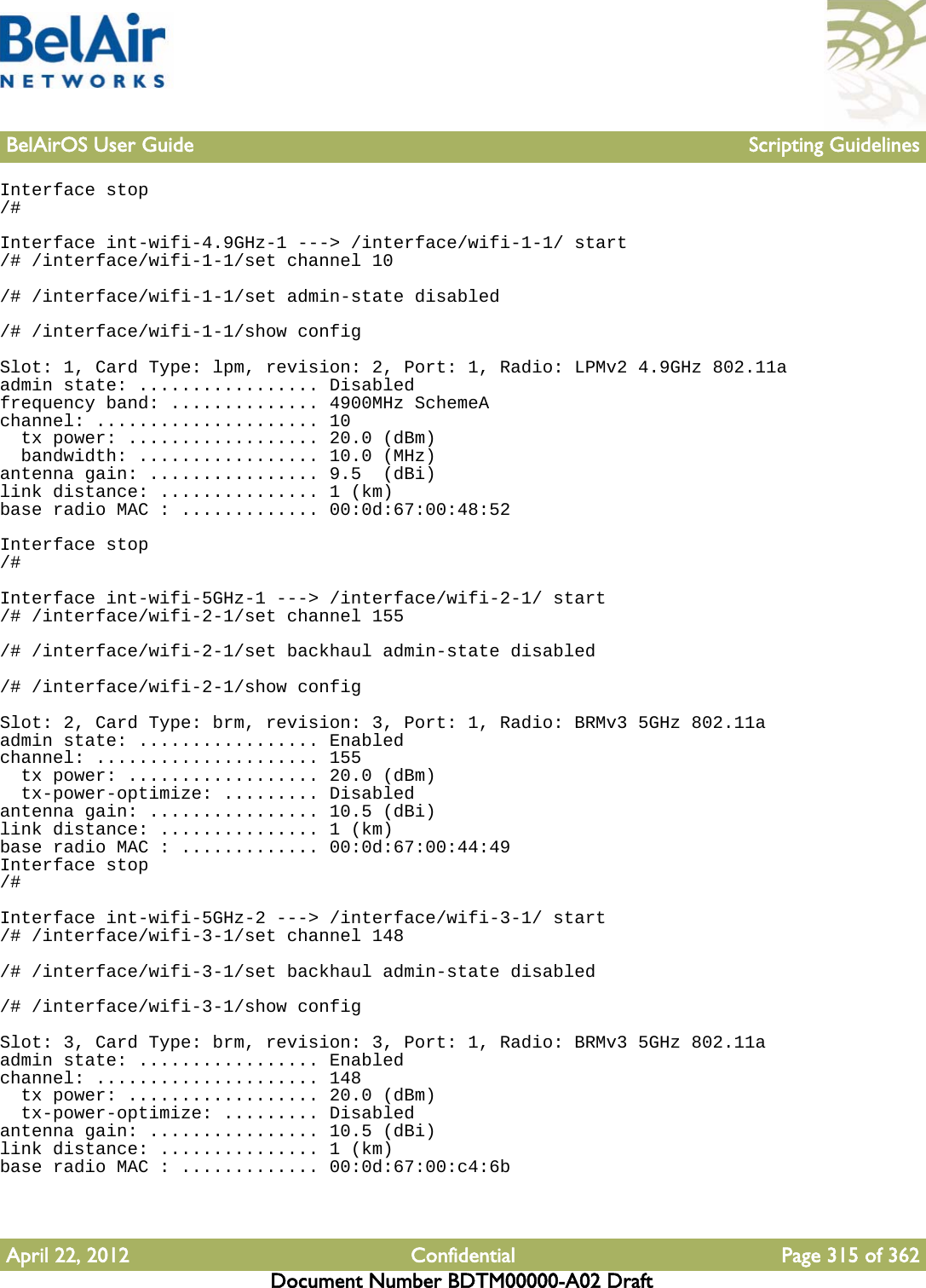
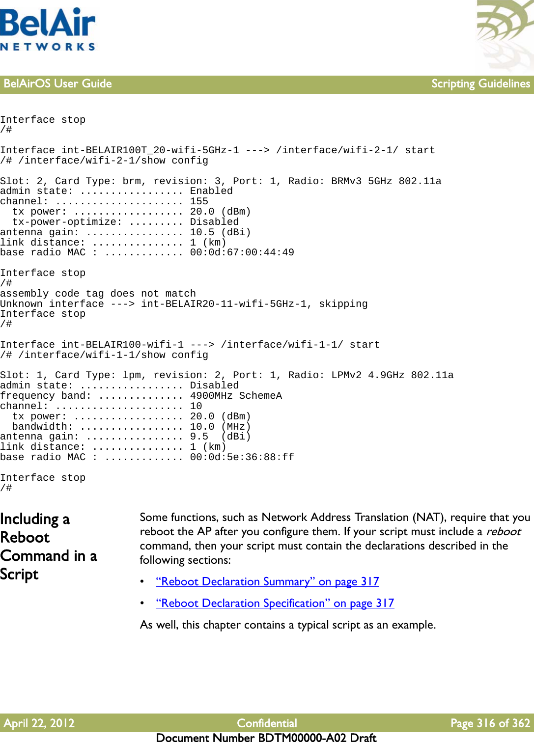
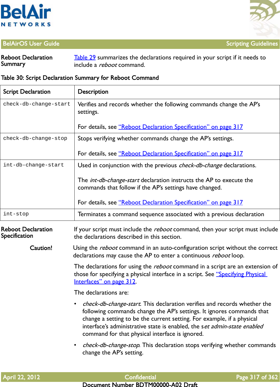
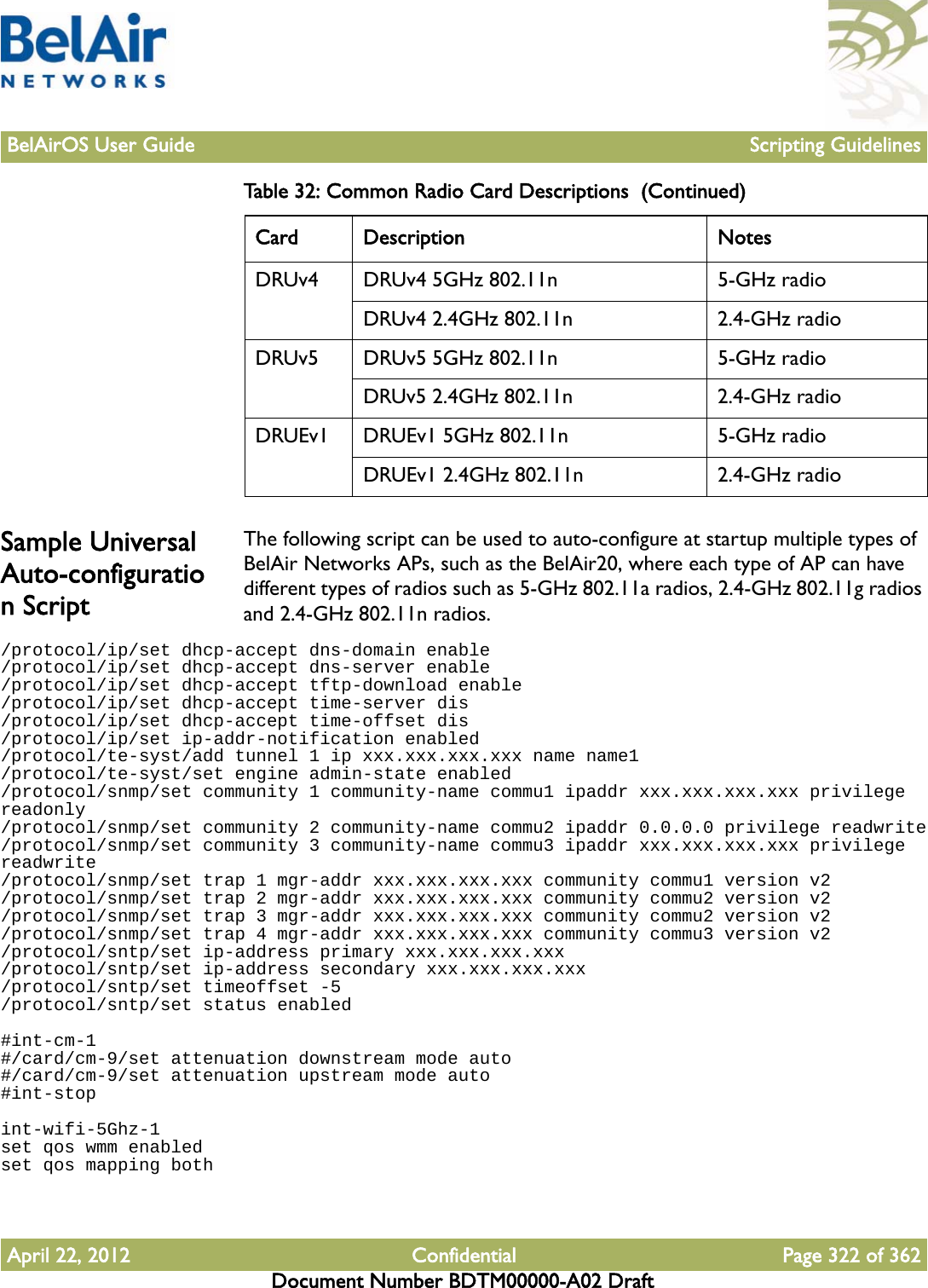
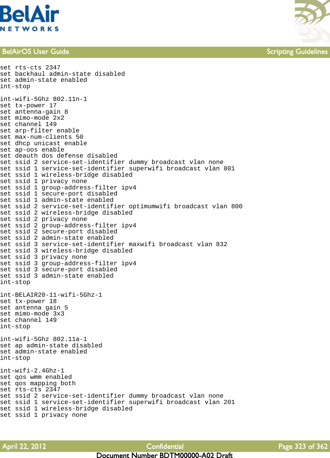
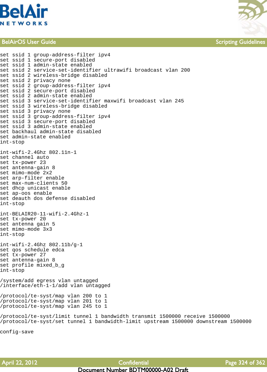
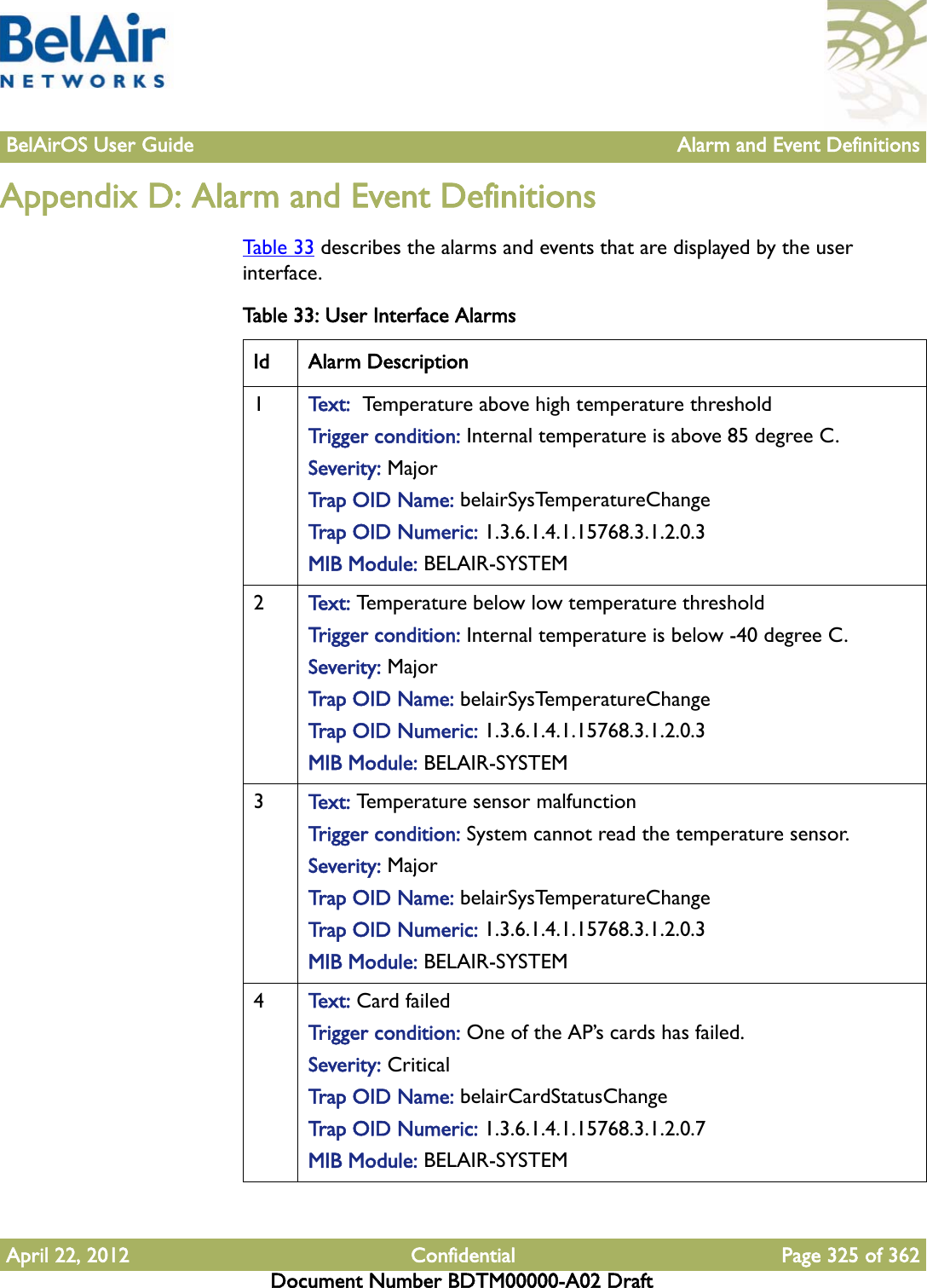
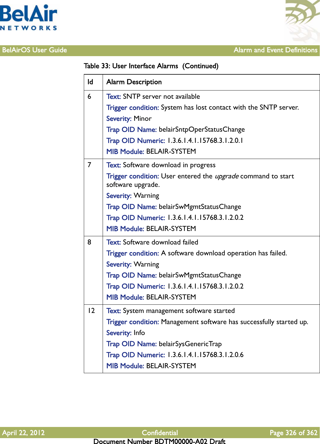
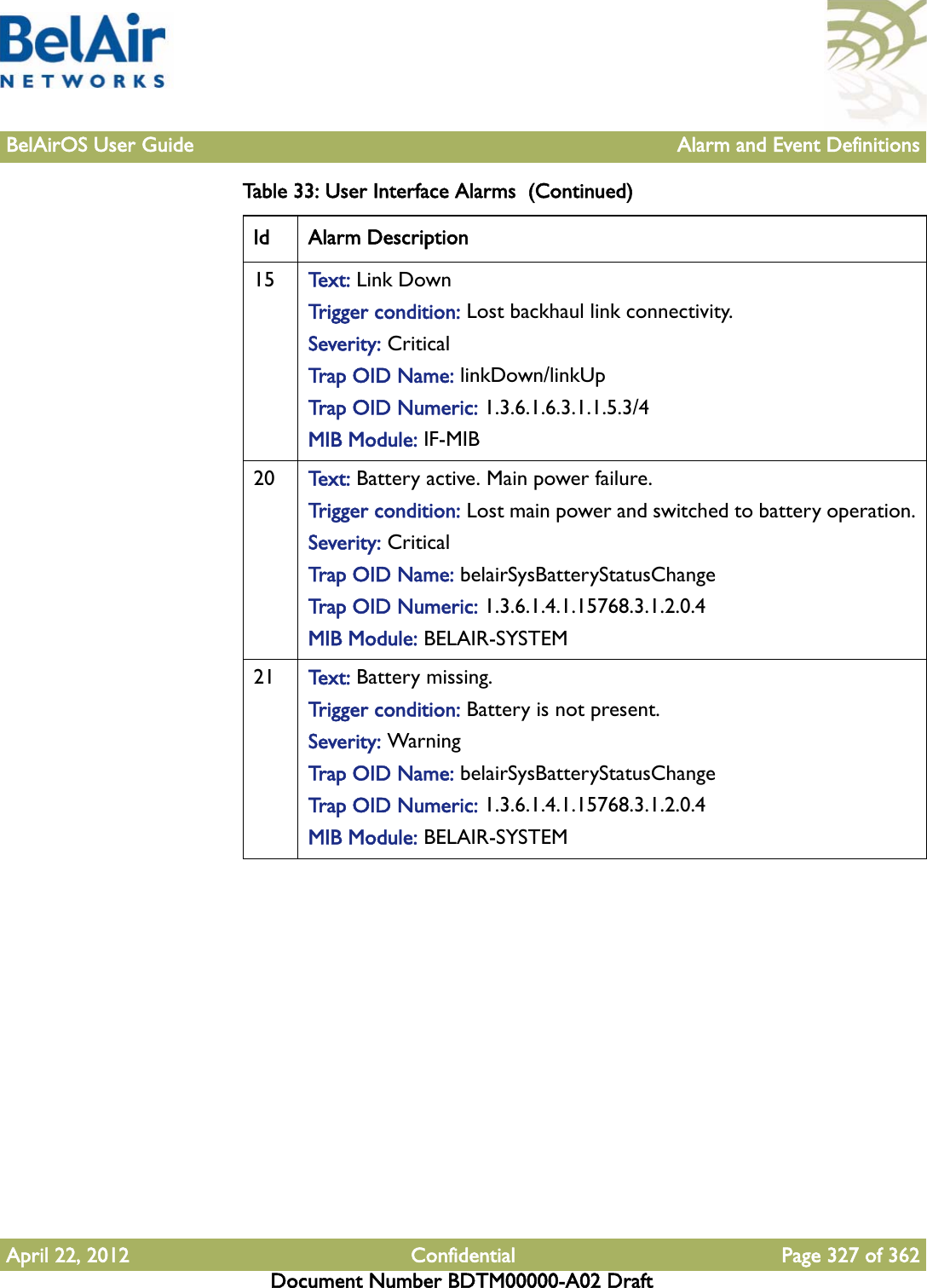
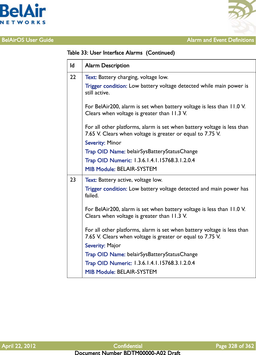
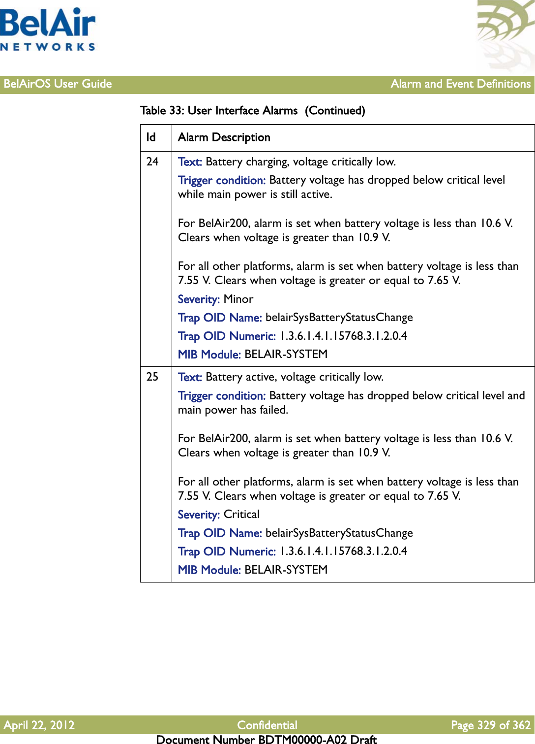
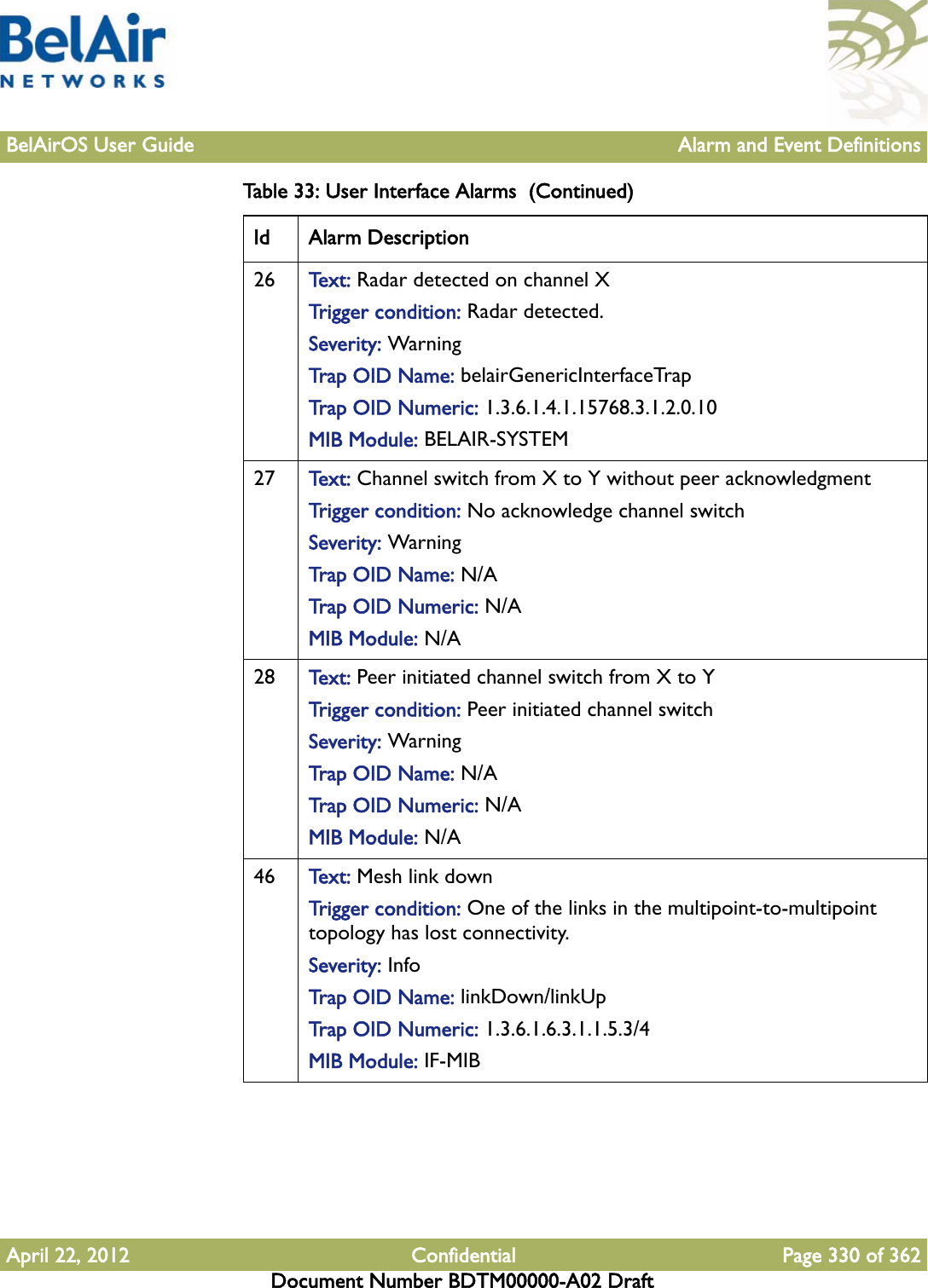

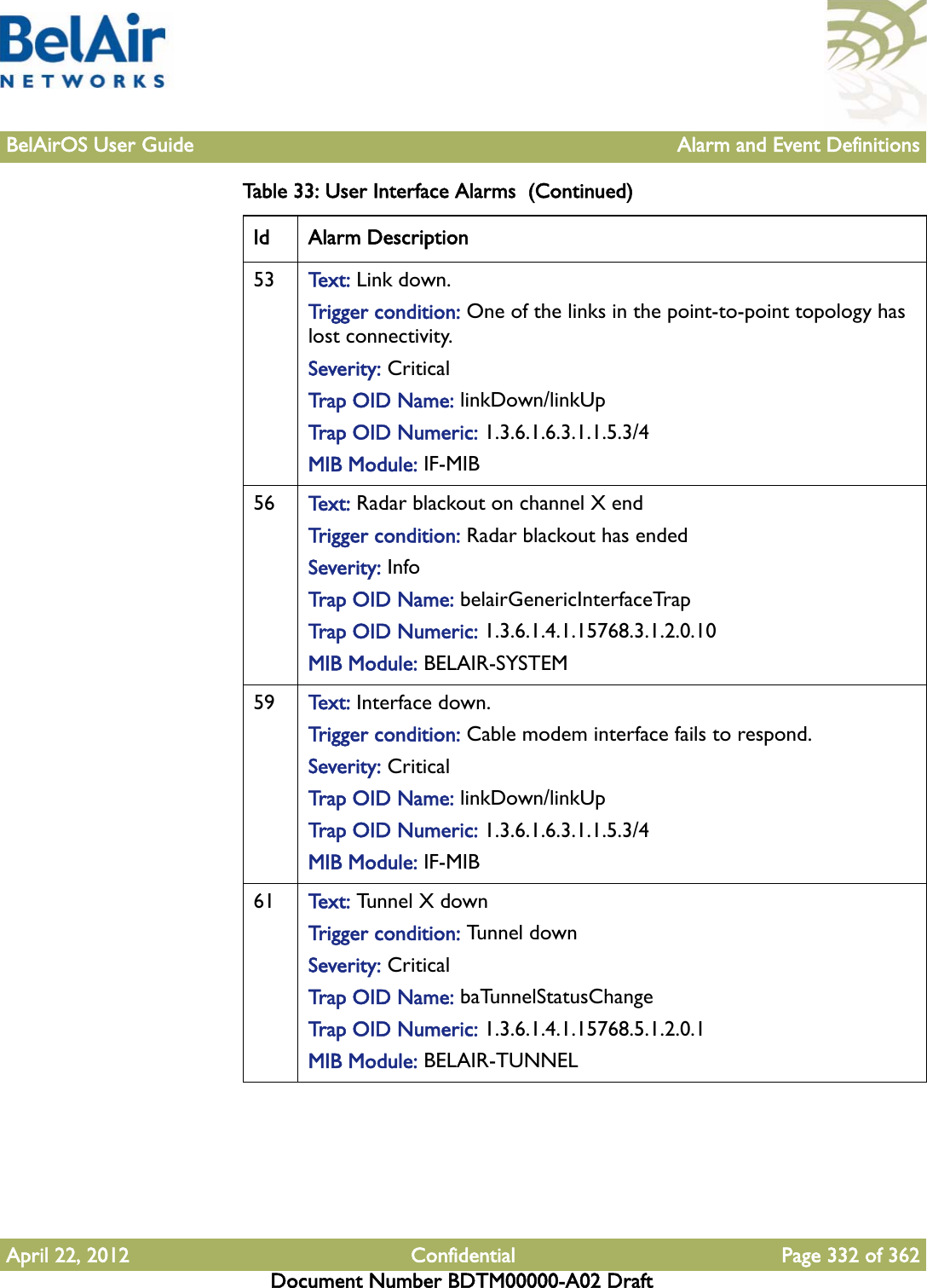
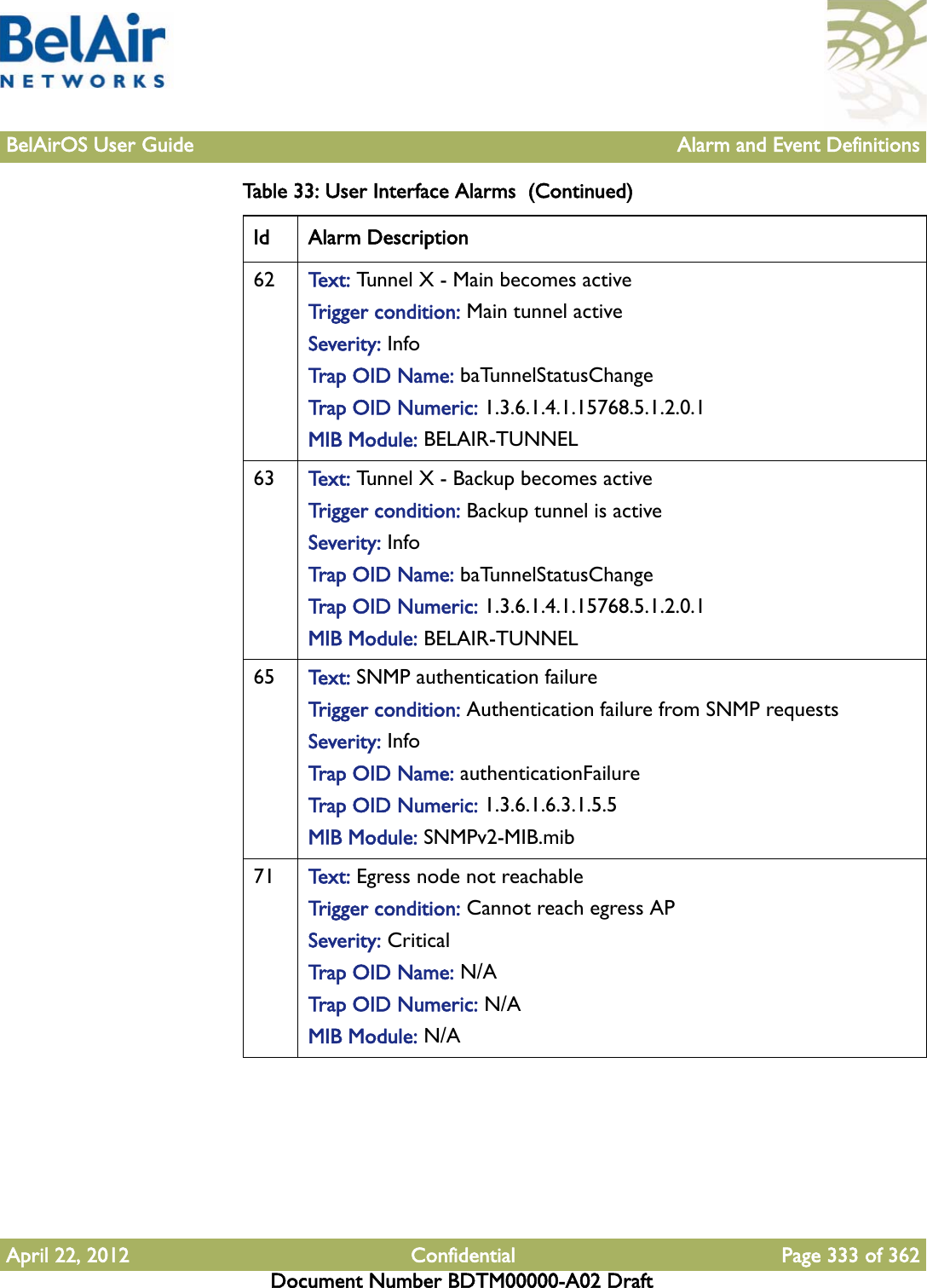
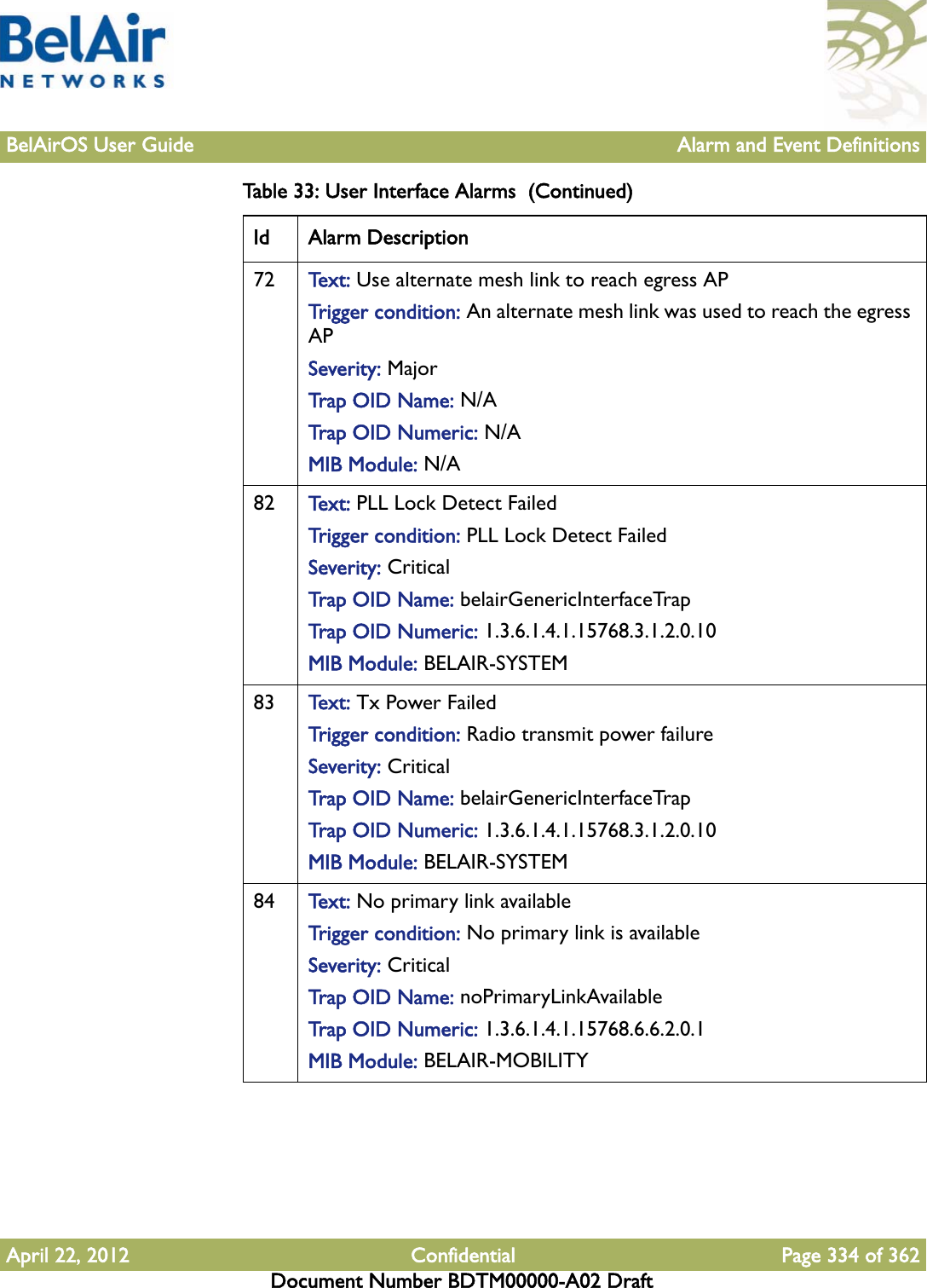
![BelAirOS User Guide Alarm and Event DefinitionsApril 22, 2012 Confidential Page 335 of 362Document Number BDTM00000-A02 Draft85 Te x t : No secondary link availableTrigger condition: No secondary link is availableSeverity: MajorTrap OID Name: noSecondaryLinkAvailableTrap OID Numeric: 1.3.6.1.4.1.15768.6.6.2.0.2MIB Module: BELAIR-MOBILITY86 Te x t : Switchover to [radio-link-name-Y] from [radio-link-name-Y] (for example, wifi2-1-1)Trigger condition: Switchover from primary to secondary linkSeverity: InfoTrap OID Name: primarySecondarySwitchoverTrap OID Numeric: 1.3.6.1.4.1.15768.6.6.2.0.3MIB Module: BELAIR-MOBILITY88 Te x t : IP address changedTrigger condition: IP address changeSeverity: InfoTrap OID Name: belairIpAddressChangeTrap OID Numeric: 1.3.6.1.4.1.15768.3.2.2.0.1MIB Module: BELAIR-IP89 Te x t : System configuration changedTrigger condition: Configuration changeSeverity: InfoTrap OID Name: belairConfigChangeTrap OID Numeric: 1.3.6.1.4.1.15768.3.1.2.0.8MIB Module: BELAIR-SYSTEMTable 33: User Interface Alarms (Continued)Id Alarm Description](https://usermanual.wiki/Ericsson-Wi-Fi/40005011.User-Manual/User-Guide-1698497-Page-335.png)
![BelAirOS User Guide Alarm and Event DefinitionsApril 22, 2012 Confidential Page 336 of 362Document Number BDTM00000-A02 Draft90 Te x t : Cable modem IP address changedTrigger condition: Cable modem configuration changeSeverity: InfoTrap OID Name: belairCmIpAddressChangeTrap OID Numeric: 1.3.6.1.4.1.15768.6.4.2.0.1MIB Module: BE BELAIR-CABLE-MODEM91 Te x t : Secure MAC [AA:BB:CC:DD:EE:FF] spoofTrigger condition: The AP has detected a secure MAC address spoof attack.Severity: WarningTrap OID Name: belairDot11SecureMacSpoofedTrap OID Numeric: : 1.3.6.1.4.1.15768.4.2.0.1MIB Module: BELAIR-IEEE802DOT1192 Te x t : DHCP attackTrigger condition: The AP has detected a secure DHCP starvation attack.Severity: WarningTrap OID Name: belairDot11DhcpAttackTrap OID Numeric: 1.3.6.1.4.1.15768.4.2.0.2MIB Module: BELAIR-IEEE802DOT1193 Te x t : 1-2, 00:01:23:45:67:89 AuthenticatedTrigger condition: Radio has authenticated a clientSeverity: InfoTrap OID Name: belairDot11ClientAuthenticatedTrap OID Numeric: 1.3.6.1.4.1.15768.4.7.2.0.1MIB Module: BELAIR-IEEE802DOT11-CLIENTNote: Due to the frequency of client authentication traps, this trap does not appear in the alarm history.Table 33: User Interface Alarms (Continued)Id Alarm Description](https://usermanual.wiki/Ericsson-Wi-Fi/40005011.User-Manual/User-Guide-1698497-Page-336.png)
![BelAirOS User Guide Alarm and Event DefinitionsApril 22, 2012 Confidential Page 337 of 362Document Number BDTM00000-A02 Draft98 Te x t : Authentication fail: IP_ADDRESS [detail]Trigger condition: Authentication failure when user logs in through CLI or Web interface.Severity: InfoTrap OID Name: belairAuthenticationFailureTrap OID Numeric: 1.3.6.1.4.1.15768.3.1.2.0.9MIB Module: BELAIR-SYSTEM99 Te x t : Authentication fail: <%s> [%s]Trigger condition: STP Topology changeSeverity: InfoTrap OID Name: baRstpTopologyChangedTrap OID Numeric: 1.3.6.1.4.1.15768.5.2.2.0.1MIB Module: BELAIR-RSTP100 Te x t : Configuration change unsavedTrigger condition: Unsaved configuration changeSeverity: WarningTrap OID Name: belairSysConfigUnsavedTrap OID Numeric: 1.3.6.1.4.1.15768.3.1.1.2.16MIB Module: BELAIR-SYSTEM103 Te x t : Protection link down, link x peer 00:0d:67:12:34:56Trigger condition: When link status for a backhaul protection link changesSeverity: InfoTrap OID Name: linkDown/linkUpTrap OID Numeric: 1.3.6.1.6.3.1.1.5.3/1.3.6.1.6.3.1.1.5.4MIB Module: IF-MIBTable 33: User Interface Alarms (Continued)Id Alarm Description](https://usermanual.wiki/Ericsson-Wi-Fi/40005011.User-Manual/User-Guide-1698497-Page-337.png)