Ericsson Wi Fi 40005011 802.11n dual-band WIFI router User Manual BelAirOS User Guide
Ericsson Wi-Fi 802.11n dual-band WIFI router BelAirOS User Guide
Contents
User Manual

BelAirOS
Page 1 of 362
Release: 12.2
Document Date: April 22, 2012
Document Number: BDTM00000-A02
Document Status: Draft
Security Status: Confidential
Customer Support: 613-254-7070
1-877-BelAir1 (235-2471)
techsupport@belairnetworks.com
© Copyright 2012 by BelAir Networks.
The information contained in this document is confidential and proprietary to BelAir Networks. Errors and Omissions Excepted.
Specification may be subject to change. All trademarks are the property of their respective owners.
Protected by U.S. Patents: 7,171,223 / 7,164,667 / 7,154,356 / 7,030,712 / D501,195 / 7,545,782 / 7,433,343 / 7,162,234 and 7,433,361.
Patents pending in the U.S. and other countries.
BelAir Networks, the BelAir Logo, BelAir200, BelAir200D, BelAir100, BelAir100S, BelAir100C, BelAir100T, BelAir20, BelAir20M, BelAir20E, BelAir20EO, BelAir100M,
BelAir100i, BelAir100SN, BelAir100SNE, BelAir100N, BelAir100NE, BelAir100P, BelAir1000, BelAir1100, BelAir2100, BelAir3200, BelAirCC8000, BelView, BelView
NMS and BelAir Business Intelligence are trademarks of BelAir Networks Inc.
BelAirOS
User Guide

April 22, 2012 Confidential Page 2 of 362
Document Number BDTM00000-A02 Draft
BelAirOS User Guide Contents
Contents
About This Document . . . . . . . . . . . . . . . . . . . . . . . . . . . . . . . . . . . 4
System Overview of BelAir Networks APs . . . . . . . . . . . . . . . . . . . 5
AP Configuration Interfaces . . . . . . . . . . . . . . . . . . . . . . . . . . . . . . 21
Command Line Interface Basics . . . . . . . . . . . . . . . . . . . . . . . . . . . 27
AP Access Methods . . . . . . . . . . . . . . . . . . . . . . . . . . . . . . . . . . . . 42
User and Session Administration . . . . . . . . . . . . . . . . . . . . . . . . . . 52
IP Settings . . . . . . . . . . . . . . . . . . . . . . . . . . . . . . . . . . . . . . . . . . . . 61
System Settings . . . . . . . . . . . . . . . . . . . . . . . . . . . . . . . . . . . . . . . . 66
AP Auto-configuration . . . . . . . . . . . . . . . . . . . . . . . . . . . . . . . . . . 78
Card Settings. . . . . . . . . . . . . . . . . . . . . . . . . . . . . . . . . . . . . . . . . . 84
Ethernet or LAN Interface Settings . . . . . . . . . . . . . . . . . . . . . . . . 91
Cable Modem Configuration . . . . . . . . . . . . . . . . . . . . . . . . . . . . . 96
Wi-Fi Radio Configuration Overview . . . . . . . . . . . . . . . . . . . . . 101
Configuring Wi-Fi Radio Parameters . . . . . . . . . . . . . . . . . . . . . . 103
Configuring Wi-Fi Access Point Parameters . . . . . . . . . . . . . . . . 123
Wi-Fi AP Security . . . . . . . . . . . . . . . . . . . . . . . . . . . . . . . . . . . . . 146
Wi-Fi Backhaul Link Configuration . . . . . . . . . . . . . . . . . . . . . . . 161
Mobile Backhaul Mesh . . . . . . . . . . . . . . . . . . . . . . . . . . . . . . . . . 169
Mobile Backhaul Point-to-point Links . . . . . . . . . . . . . . . . . . . . . 173
Operating in High Capacity and Interference Environments. . . . 184
DHCP Relay Settings . . . . . . . . . . . . . . . . . . . . . . . . . . . . . . . . . . 191
Network Address Translation . . . . . . . . . . . . . . . . . . . . . . . . . . . 196

April 22, 2012 Confidential Page 3 of 362
Document Number BDTM00000-A02 Draft
BelAirOS User Guide Contents
Universal Access Method . . . . . . . . . . . . . . . . . . . . . . . . . . . . . . . 201
Using Layer 2 Tunnels . . . . . . . . . . . . . . . . . . . . . . . . . . . . . . . . . 210
Quality of Service Settings . . . . . . . . . . . . . . . . . . . . . . . . . . . . . . 225
Layer 2 Network Configuration. . . . . . . . . . . . . . . . . . . . . . . . . . 231
Performing a Software Upgrade. . . . . . . . . . . . . . . . . . . . . . . . . . 246
Alarm and Event Reporting . . . . . . . . . . . . . . . . . . . . . . . . . . . . . 254
Using Syslog . . . . . . . . . . . . . . . . . . . . . . . . . . . . . . . . . . . . . . . . . 258
Gathering Additional Troubleshooting Information . . . . . . . . . . 262
Troubleshooting Wireless Client Connections. . . . . . . . . . . . . . 265
Running Link Diagnostics . . . . . . . . . . . . . . . . . . . . . . . . . . . . . . . 273
Web Radio Troubleshooting Tools . . . . . . . . . . . . . . . . . . . . . . . 277
AP LED Descriptions . . . . . . . . . . . . . . . . . . . . . . . . . . . . . . . . . . 280
For More Information. . . . . . . . . . . . . . . . . . . . . . . . . . . . . . . . . . 291
Technical Support. . . . . . . . . . . . . . . . . . . . . . . . . . . . . . . . . . . . . 293
Definitions and Acronyms . . . . . . . . . . . . . . . . . . . . . . . . . . . . . . 294
Appendix A: AP Configuration Sheets . . . . . . . . . . . . . . . . . . . . 296
Appendix B: Mesh Auto-connection Example . . . . . . . . . . . . . . 299
Appendix C: Scripting Guidelines . . . . . . . . . . . . . . . . . . . . . . . . 309
Appendix D: Alarm and Event Definitions . . . . . . . . . . . . . . . . . 325
Appendix E: Resetting to Factory Defaults . . . . . . . . . . . . . . . . . 339
Detailed Table of Contents . . . . . . . . . . . . . . . . . . . . . . . . . . . . . 345

BelAirOS User Guide About This Document
April 22, 2012 Confidential Page 4 of 362
Document Number BDTM00000-A02 Draft
About This Document
This document provides the information you need to install and configure
BelAir Networks Wi-FI Access Points (APs) using the BelAirOS Operating
System, and the procedures for using the AP Command Line Interface (CLI).
This document may contain alternate references to APs. Ta b l e 1 shows possible
synonyms to the product name.
Typ o graph ic al
Conventions
This document uses the following typographical conventions:
• Text in < > indicates a parameter required as input for a CLI command;
for example, < IP address >
• Text in [ ] indicates optional parameters for a CLI command.
• Text in { } refers to a list of possible entries with | as the separator.
• Parameters in ( ) indicate that at least one of the parameters must entered.
Related
Documentation
The following titles are BelAir Networks reference documents:
•
BelAir20 Quick Install Guide
•
BelAir100i WCS Quick Install Guide
•
BelAir20E Quick Install Guide
•
BelAir20EO Quick Install Guide
• WCSv1 Deployment and Installation Technical Bulletin
•
BelAir100SN Installation Guide
•
BelAir100SNE Installation Guide
•
BelAir100N Installation Guide
•
BelAir2100 Metrocell Installation Guide
•
BelAir2100 Metrocell Cellular Reference Guide
Table 1: Product Name Synonyms
Product Name Synonym
BelAir100N™ BA100N
BelAir2100™ BA100P
BelAir100SN™, BelAir100SNE™ BA100S
BelAir20™, BelAir100i WCS, BelAir20E™, BelAir20EO™ BA20

BelAirOS User Guide System Overview of BelAir Networks APs
April 22, 2012 Confidential Page 5 of 362
Document Number BDTM00000-A02 Draft
System Overview of BelAir Networks APs
This chapter provides a brief systems description of each available BelAir
Networks AP, including an overview of its hardware modules. This chapter
defines terms of reference used through the rest of the document. The APS are
described in the following sections:
•“BelAir20” on page 5
•“BelAir100i WCS” on page 7
•“BelAir20E” on page 9
•“BelAir20EO” on page 11
•“BelAir100N” on page 12
•“BelAir100SN” on page 14
•“BelAir100SNE” on page 16
•“BelAir2100” on page 18
BelAir20 The BelAir20 is a Wi-Fi access point that meets IEEE 802.11n standards. It is
fully interoperable with existing 802.11a/b/g standards, providing a transparent,
wireless high speed data communication between the wired LAN and fixed or
mobile devices. The unit includes three detachable dual-band
2.4/5.8 GHz antennas with the option to attach higher specification external
antennas that boost network coverage. A power adapter and all required
mounting hardware is also included.
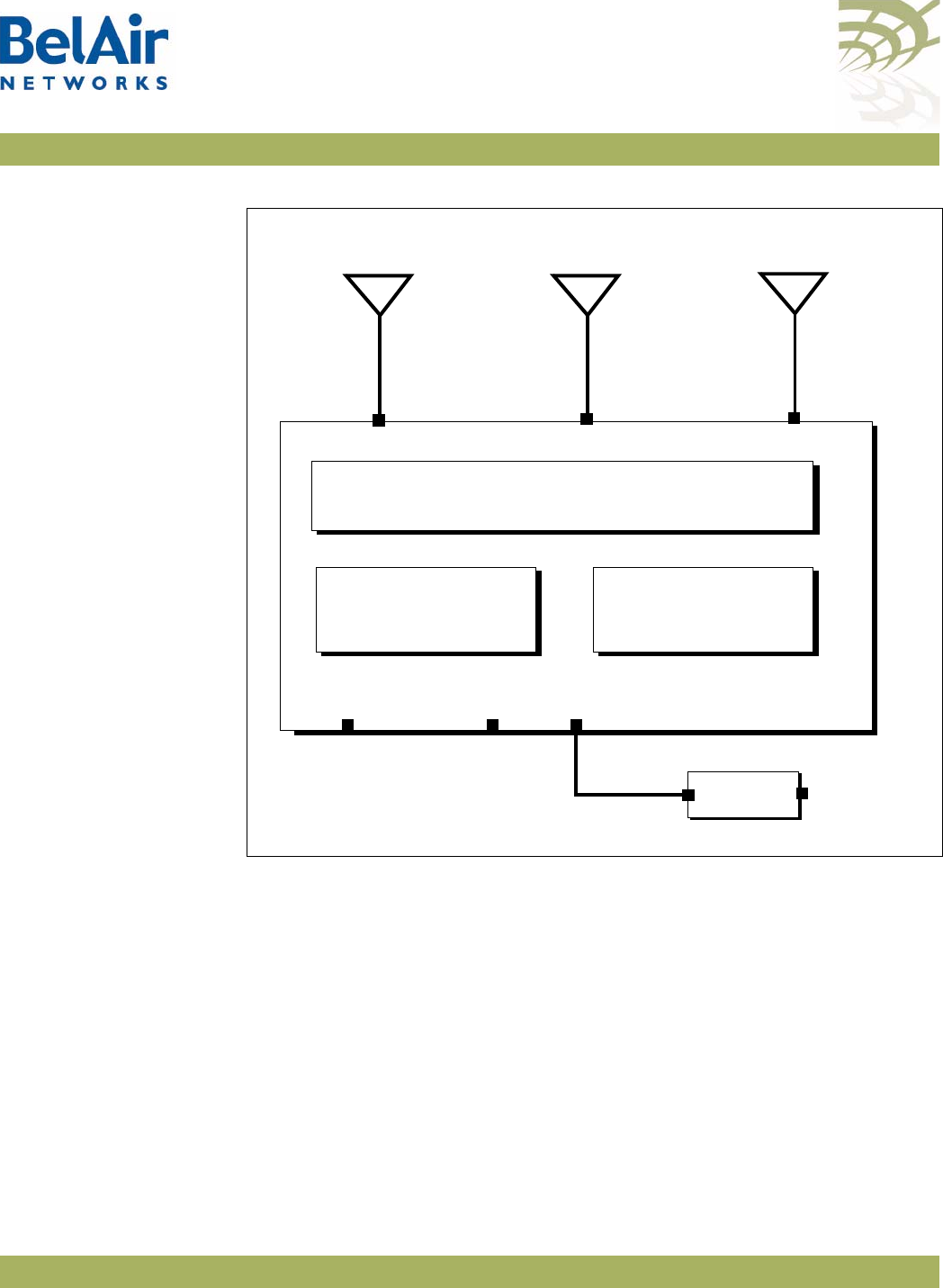
BelAir20 Hardware
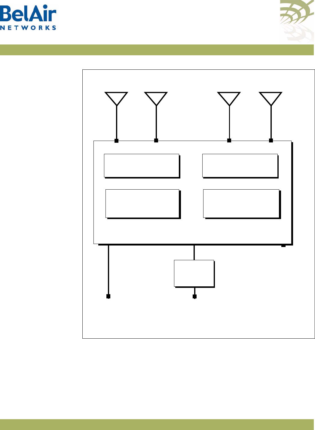
Description Figure 1 shows the relationship between the main BelAir20 hardware modules.
BelAirOS User Guide System Overview of BelAir Networks APs
April 22, 2012 Confidential Page 6 of 362
Document Number BDTM00000-A02 Draft
Figure 1: BelAir20 Hardware Module Block Diagram
The BelAir20 consists of the following modules:
• one High Throughput Module (HTM) providing:
—a wireline 10/100/1000 Base-TX Ethernet interface to the Internet
—a 2.4 GHz Wi-Fi radio and a 5.8 GHz Wi-Fi radio using enhanced
performance links. Each radio can act as an Access Point (AP) or provide
backhaul links. An AP provides user traffic wireless access to the
BelAir20. Backhaul links connect to other BelAir Networks radios to
create a radio mesh.
• three detachable dual-band antennas
• an external connector field
HTM
5.8 GHz
Radio
AC Power
Adapter
Antenna 0
Ethernet
10Base-TX
100Base-TX
1000Base-TX
48 V DC
Antenna 1 Antenna 2
2.4 GHz
Radio
100-240 V AC
Reset
Diplexer

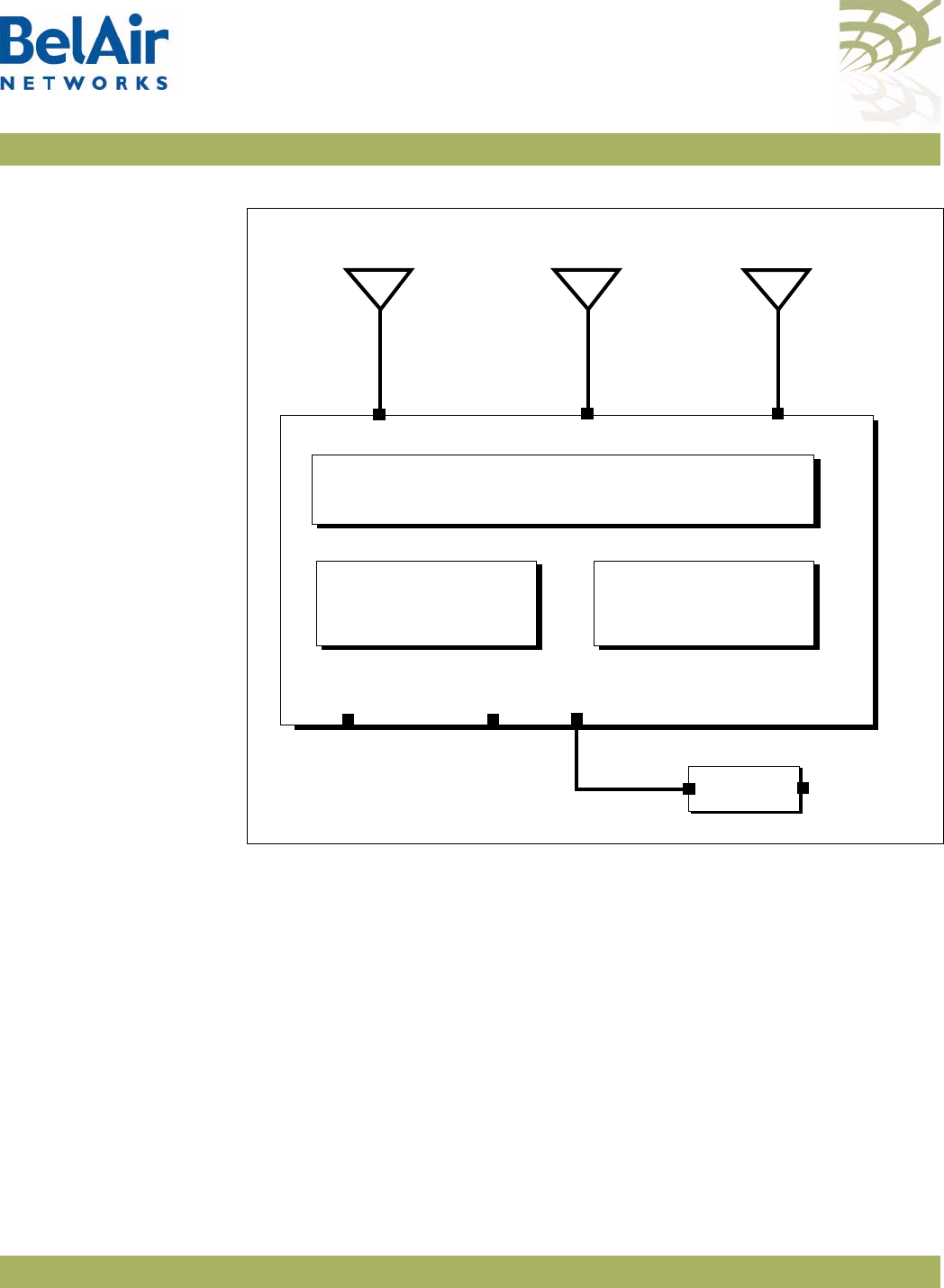
BelAirOS User Guide System Overview of BelAir Networks APs
April 22, 2012 Confidential Page 7 of 362
Document Number BDTM00000-A02 Draft
BelAir20 Antenna
Connectivity Tabl e 2 shows which antennas to connect for 802.11a/b/g/n operation.
BelAir100i WCS The BelAir100i WCS is a Wi-Fi access point that meets IEEE 802.11n standards.
It is fully interoperable with existing 802.11b/g standards, providing a
transparent, wireless high speed data communication between the wired LAN
and fixed or mobile devices. The unit includes three detachable dual-band
2.4 GHz antennas with the option to attach higher specification external
antennas that boost network coverage. A power adapter and all required
mounting hardware is also included.
BelAir100i WCS
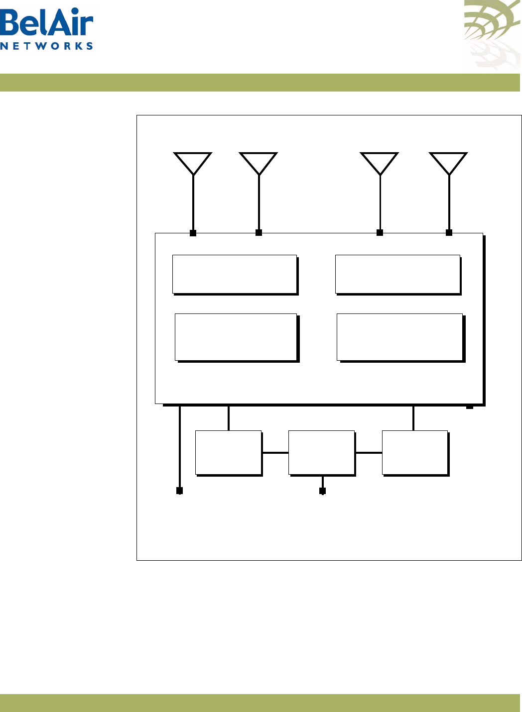
Hardware Description Figure 2 shows the relationship between the main BelAir100i WCS hardware
modules.
Table 2: BelAir20 Antenna Connectivity
Radio Operation
BelAir20 Ports to Connect to Antennas
2.4 GHz Radio 5.0 GHz Radio
802.11a n/a all1
802.11b/g all1n/a
802.11n, 1x1 MIMO 0 1
802.11n, 2x2 MIMO 0, 2 1, 2
802.11n, 3x3 MIMO all1all1
Note 1: For 802.11a/b/g operation, all antennas carry the same data. For
802.11n operation, different antennas carry different data.
BelAirOS User Guide System Overview of BelAir Networks APs
April 22, 2012 Confidential Page 8 of 362
Document Number BDTM00000-A02 Draft
Figure 2: BelAir100i WCS Hardware Module Block Diagram
The BelAir100i WCS consists of the following modules:
• one High Throughput Module (HTM) providing:
—a wireline 10/100/1000 Base-TX Ethernet interface to the Internet
—a 2.4 GHz Wi-Fi radio and a 2.3 GHz WCS Wi-Fi radio using enhanced
performance links. The 2.4 GHz radio can act as an Access Point (AP) or
provide backhaul links. The 2.3 GHz WCS radio can provide backhaul
links. An AP provides user traffic wireless access to the BelAir100i WCS.
Backhaul links connect to other BelAir Networks radios to create a radio
mesh.
• three detachable dual-band antennas
• an external connector field
HTM
2.3 GHz WCS
Radio
AC Power
Adapter
Antenna 0
Ethernet
10Base-TX
100Base-TX
1000Base-TX
48 V DC
Antenna 1
2.4 GHz
Radio
100-240 V AC
Reset
Diplexer
Antenna 2

BelAirOS User Guide System Overview of BelAir Networks APs
April 22, 2012 Confidential Page 9 of 362
Document Number BDTM00000-A02 Draft
BelAir100i WCS
Antenna Connectivity Refer to the
WCSv1 Deployment and Installation Technical Bulletin
.
BelAir20E The BelAir20E Access Point (AP) is an evolution of BelAir Networks indoor
solution and part of BelAir Networks industry leading product portfolio. The
BelAir20E adds standards-based beamforming, five Gigabit Ethernet ports
(one WAN port with PoE and four LAN ports), integrated antennas, and full
802.11n compliance (802.11n-2009) to BelAir Networks leading low cost, high
capacity indoor access.
The next generation BelAir20E continues to lead with the industry’s highest
performance and most flexible indoor Wi-Fi AP. Offering all the same features
and management as the other BelAir Networks products, the BelAir20E has
been optimized for managed hot spot applications, with Edge Policy
Enforcement using centralized control and a true Plug-and-Play architecture.
And, with the latest fully compliant 802.11n, it is ideal for even the most
demanding applications, including voice and video. The BelAir20E also provides
connectivity between indoor and outdoor networks, enabling true
standards-based seamless mobility as users move from outside to inside.
The operating temperature of the BelAir20E is -20 ºC to +45 ºC.
The BelAir20E is available in following models:
• The BelAir20E-11 contains both a 2.4 GHz radio and a 5.8 GHz radio.
• The BelAir20E-10 contains only a 2.4 GHz radio.
This document may describe 5.8 GHz radio functionality. In such case, the
descriptions apply to the BelAir20E-11 model only. They do not apply to the
BelAir20E-10 model.
The BelAir20E is available in following variants:
• The BelAir20E-11 and the BelAir20E-10 are available for the USA only.
Operators of the BelAir20E-11 and the BelAir20E-10 can set the country of
operation only to
US
. Similarly, the operating channels, antenna gain, and the
transmit power levels can be set only to values that are valid for the USA.
• The BelAir20E-11R and the BelAir20E-10R are available for countries other
than the USA. Operators of the BelAir20E-11R and the BelAir20E-10R can
set the country of operation to any BelAir Networks approved country.
Similarly, the operating channels, antenna gain, and the transmit power levels
can be set to values that are valid for the specified country of operation.
BelAirOS User Guide System Overview of BelAir Networks APs
April 22, 2012 Confidential Page 10 of 362
Document Number BDTM00000-A02 Draft
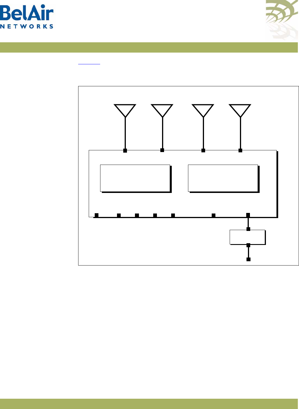
BelAir20E Hardware
Description Figure 3 shows the relationship between the main BelAir20E hardware
modules.
Figure 3: BelAir20E Hardware Module Block Diagram
The BelAir20E consists of the following modules:
• one High Throughput Module Evolved (HTME) providing:
—a wireline 10/100/1000 Base-TX WAN Ethernet interface to the Internet
—four wireline 10/100/1000 Base-TX LAN Ethernet interfaces
—a 2.4 GHz Wi-Fi radio and a 5.8 GHz Wi-Fi radio (-11 model only) using
fully compliant 802.11n links. E Each radio can act as an Access Point (AP)
or provide backhaul links. An AP provides user traffic wireless access to
the BelAir20E. Backhaul links connect to other BelAir Networks radios
to create a radio mesh.
• four integrated dual-band antennas (-11 model only)
• an external connector field
HTME
5.8 GHz
Radio
AC Power
Adapter
Antenna 0
LAN 48 V DC
Antenna 1 Antenna 2
2.4 GHz
Radio
100-240 V AC
Reset
Antenna 3
WAN
PoE
LAN LAN LAN
-11 model only
-11 model only -11 model only

BelAirOS User Guide System Overview of BelAir Networks APs
April 22, 2012 Confidential Page 11 of 362
Document Number BDTM00000-A02 Draft
BelAir20EO The BelAir20EO Outdoor Access Point (AP) is an extension of BelAir
Networks outdoor solutions and part of BelAir Networks industry leading
product portfolio. The BelAir20EO addresses new deployment models and
regional requirements and is part of BelAir Networks portfolio of outdoor
hardened products. The BelAir20EO also adds standards-based beamforming,
Gigabit Ethernet ports (one WAN port with PoE in and one LAN port),
integrated or external antennas, and full 802.11n compliance (802.11n-2009) in
a compact, streamlined package.
The next generation BelAir20EO continues to lead with the industry’s highest
performance and most flexible outdoor Wi-Fi AP. Offering all the same features
and management as the other BelAir Networks products, the BelAir20EO has
been optimized for managed Hot Zone and 3G Offload applications, with Edge
Policy Enforcement using centralized control and a true Plug-and- Play
architecture. And, with the latest fully compliant 802.11n, it is ideal for even the
most demanding applications, including voice and video. The BelAir20EO also
provides connectivity between indoor and outdoor networks, enabling true
standards-based seamless mobility as users move from outside to inside.
The operating temperature of the BelAir20EO is -20 ºC to +45 ºC.
The BelAir20EO is available in following variants:
• The BelAir20EO-11 is available for the USA only. Operators of the
BelAir20EO-11 can set the country of operation only to
US
. Similarly, the
operating channels, antenna gain, and the transmit power levels can be set
only to values that are valid for the USA.
• The BelAir20EO-11R is available for countries other than the USA.
Operators of the BelAir20EO-11R can set the country of operation to any
BelAir Networks approved country. Similarly, the operating channels,
antenna gain, and the transmit power levels can be set to values that are
valid for the specified country of operation.
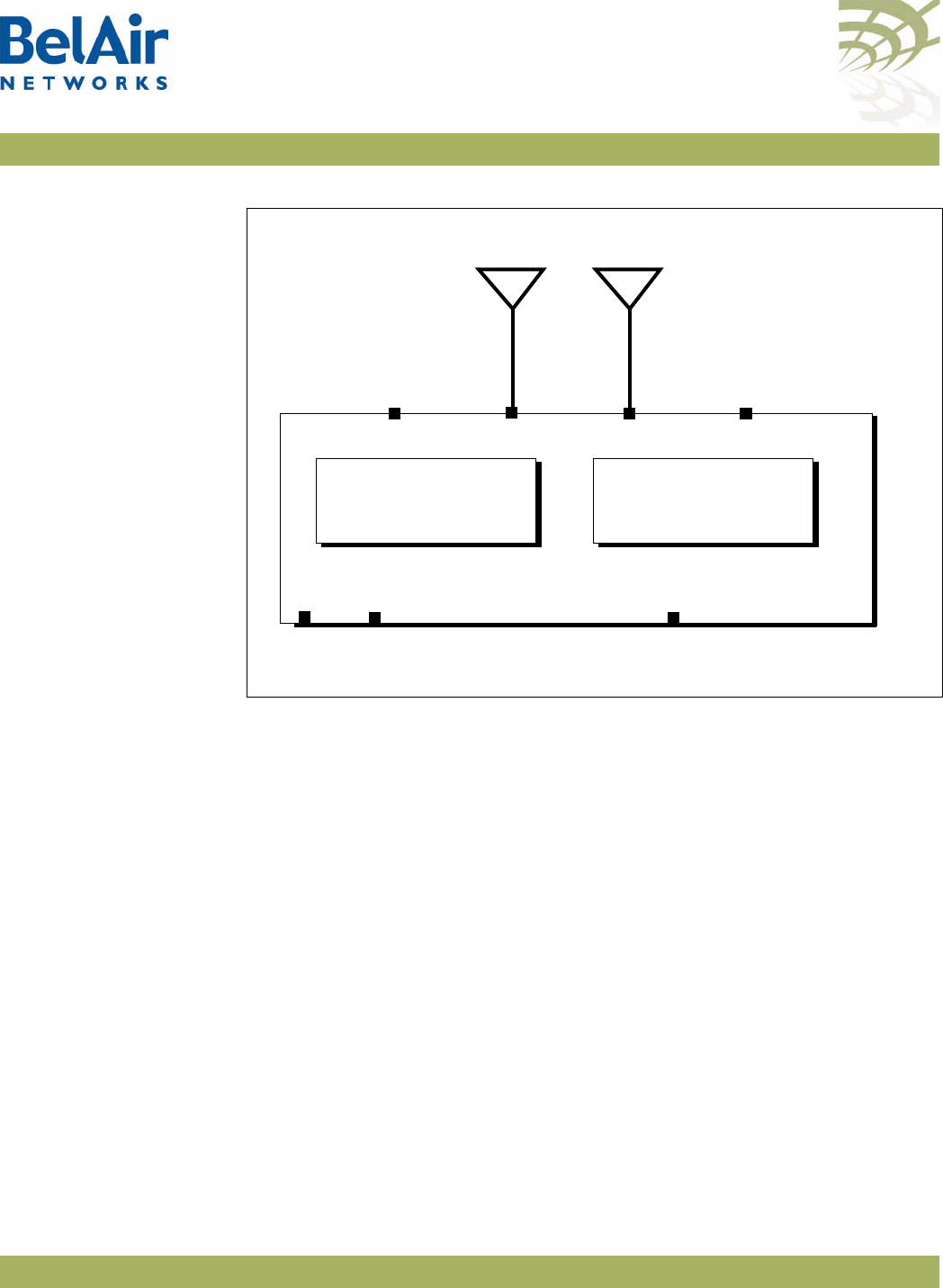
BelAir20EO Hardware
Description Figure 4 on page 12 shows the relationship between the main BelAir20EO
hardware modules.
BelAirOS User Guide System Overview of BelAir Networks APs
April 22, 2012 Confidential Page 12 of 362
Document Number BDTM00000-A02 Draft
Figure 4: BelAir20EO Hardware Module Block Diagram
The BelAir20EO consists of the following modules:
• one High Throughput Module Evolved (HTME) providing:
—a wireline 10/100/1000 Base-TX WAN Ethernet interface to the Internet
—a wireline 10/100/1000 Base-TX LAN Ethernet interface
—a 2.4 GHz Wi-Fi radio and a 5.8 GHz Wi-Fi radio using fully compliant
802.11n links. Each radio can act as an Access Point (AP) or provide
backhaul links. An AP provides user traffic wireless access to the
BelAir20EO. Backhaul links connect to other BelAir Networks radios to
create a radio mesh.
• two integrated dual-band antennas
• an external connector field
BelAir100N The BelAir100N is a Wi-Fi access point that meets IEEE 802.11n standards. It is
fully interoperable with existing 802.11a/b/g standards, providing a transparent,
wireless high speed data communication between the wired LAN and fixed or
mobile devices.
HTME
5.8 GHz
Radio
External
Antenna
LAN
Antenna 1 Antenna 2
2.4 GHz
Radio
Reset
External
Antenna
WAN
PoE

BelAirOS User Guide System Overview of BelAir Networks APs
April 22, 2012 Confidential Page 13 of 362
Document Number BDTM00000-A02 Draft
The BelAir100N can operate as a standalone device, or participate in a BelAir
Networks mesh as an edge node or to terminate the mesh.
The 802.11n Wi-Fi radios provide user traffic wireless access to the
BelAir100N and can form point-to-point, point-to-multipoint, or
multipoint-to-multipoint mesh backhaul links.
All the members of a multipoint-to-multipoint mesh use a proprietary
algorithm based on RSTP to automatically control the creation of loops within
the mesh. This loop management function is fully transparent to customers and
under normal operating conditions, you do not need to modify any settings.
BelAir100N Hardware
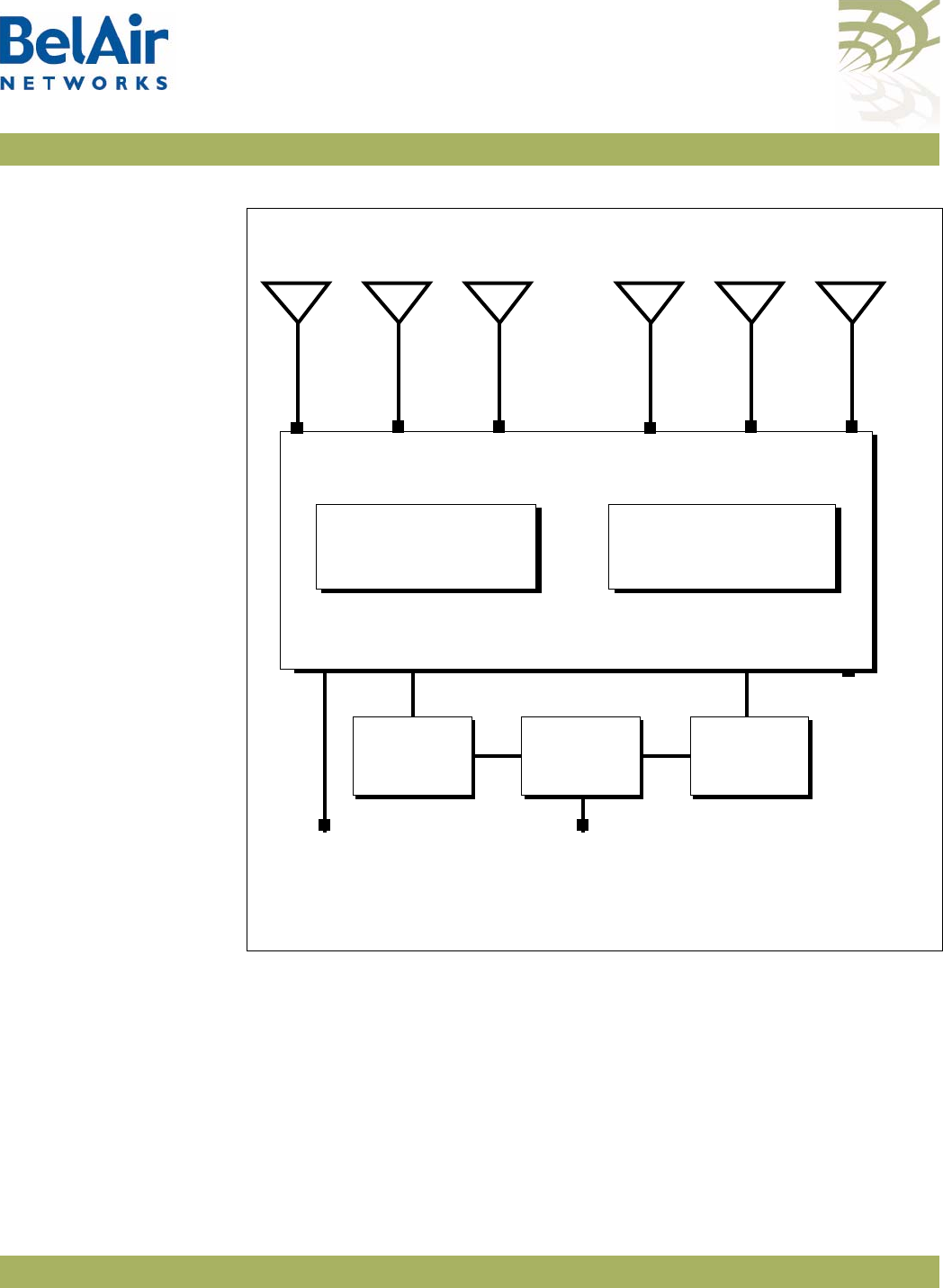
Description Figure 5 on page 14 shows the relationship between the main BelAir100N
hardware modules. The BelAir100N consists of the following modules:
• one Dual Radio Unit (DRU) providing:
—a wireline 10/100/1000 Base-TX Ethernet interface to the Internet
—a 2.4 GHz Wi-Fi radio and a 5 GHz Wi-Fi radio using enhanced
performance links. Each radio can act as an Access Point (AP) or provide
backhaul links. An AP provides user traffic wireless access to the
BelAir100N. Backhaul links connect to other BelAir Networks radios to
create a radio mesh.
• a Power Supply Unit (PSU)
• external antennas
• one environmental enclosure
• an external connector field
BelAirOS User Guide System Overview of BelAir Networks APs
April 22, 2012 Confidential Page 14 of 362
Document Number BDTM00000-A02 Draft
Figure 5: BelAir100N Hardware Module Block Diagram
BelAir100SN The BelAir100SN is a Wi-Fi access point that meets IEEE 802.11n standards. It
is fully interoperable with existing 802.11a/b/g standards, providing a
transparent, wireless high speed data communication between the wired LAN
and fixed or mobile devices.
Ethernet
10Base-TX
100Base-TX
1000Base-TX
100 to 240 V AC
40 to 154 V DC
DRU
5 GHz
Radio
Antenna 1 Antenna 3 Antenna 2
2.4 GHz
Radio
Diplexer
Reset
Antenna 4
Diplexer
Power
Supply
Unit

BelAirOS User Guide System Overview of BelAir Networks APs
April 22, 2012 Confidential Page 15 of 362
Document Number BDTM00000-A02 Draft
The BelAir100SN can operate as a standalone device, or participate in a BelAir
Networks mesh as an edge node or to terminate the mesh.
The 802.11n Wi-Fi radios provide user traffic wireless access to the
BelAir100SN and can form point-to-point, point-to-multipoint, or
multipoint-to-multipoint mesh backhaul links.
All the members of a multipoint-to-multipoint mesh use a proprietary
algorithm based on RSTP to automatically control the creation of loops within
the mesh. This loop management function is fully transparent to customers and
under normal operating conditions, you do not need to modify any settings.
BelAir100SN Hardware
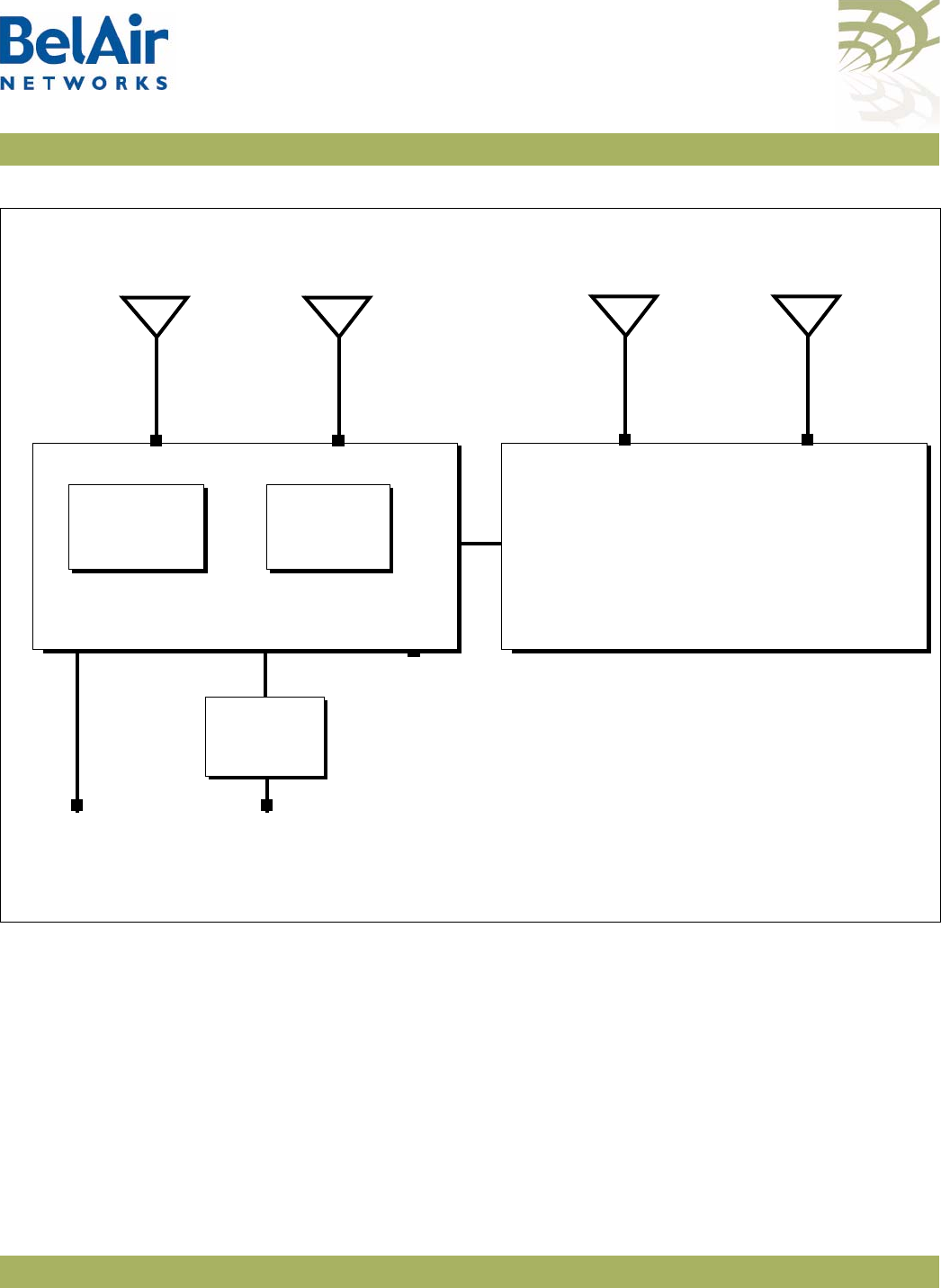
Description Figure 6 on page 16 shows the relationship between the main BelAir100SN
hardware modules. The BelAir100SN consists of the following modules:
• one Dual Radio Unit (DRU) providing:
—a wireline 10/100/1000 Base-TX Ethernet interface to the Internet
—a 2.4 GHz Wi-Fi radio and a 5 GHz Wi-Fi radio using enhanced
performance links. Each radio can act as an Access Point (AP) or provide
backhaul links. An AP provides user traffic wireless access to the
BelAir100SN. Backhaul links connect to other BelAir Networks radios to
create a radio mesh.
• a Power Protection Module (PPM) providing a wireline DOCSIS interface
and a plant interface for power
• a Cable Modem (CM)
• a Power Supply Unit (PSU)
• external antennas
• one environmental enclosure
• an external connector field
BelAirOS User Guide System Overview of BelAir Networks APs
April 22, 2012 Confidential Page 16 of 362
Document Number BDTM00000-A02 Draft
Figure 6: BelAir100SN Hardware Module Block Diagram
BelAir100SNE The BelAir100SNE is an evolution of BelAir Networks’ solution for cable
operators who want a proven and scalable strand-mount Wi-Fi AP that
integrates seamlessly with their current network and back office systems and
can be up and running live in less than 15 minutes.
Ethernet
10Base-TX
100Base-TX
1000Base-TX
DOCSIS
40 to 87 V
DRU
5 GHz
Radio
Antenna 1 Antenna 3 Antenna 2
2.4 GHz
Radio
Diplexer
Cable
Modem Power
Supply
Unit
Power
Protection
Module
Reset
Antenna 4
Diplexer

BelAirOS User Guide System Overview of BelAir Networks APs
April 22, 2012 Confidential Page 17 of 362
Document Number BDTM00000-A02 Draft
The BelAir100SNE incorporates dual 802.11n-2009 Wi-Fi 3x3 MIMO radios
and a DOCSIS® 3.0 or Euro-DOCSIS 3.0 modem on this innovative and
commercially proven AP.
The BelAir100SNE leverages the BelAirOS Operating System to support
network-wide mobility and quality of service (QoS), along with edge-based
security and policy enforcement. With BelView network management, cable
operators can manage up to 50,000 BelAir100SNE APs (or any combination of
BelAir Networks APs) in a single network. Web-based monitoring, dashboard
tools and smartphone apps provide real time network and user statistics. The
BelAir100SNE also supports TR-069 to enable integration with the operator’s
existing network management system.
BelAir100SNE
Hardware Description Figure 7 on page 18 shows the relationship between the main BelAir100SNE
hardware modules. The BelAir100SNE consists of the following modules:
• one Dual Radio Unit Evolved (DRUE) providing:
—a wireline 10/100/1000 Base-TX Ethernet interface to the Internet
—a 2.4 GHz Wi-Fi radio and a 5.8 GHz Wi-Fi radio using fully compliant
802.11n links. Each radio can act as an Access Point (AP) or provide
backhaul links. An AP provides user traffic wireless access to the
BelAir100SNE. Backhaul links connect to other BelAir Networks radios
to create a radio mesh.
• a Power Protection Module (PPM) providing a wireline DOCSIS interface
and a plant interface for power
• a Cable Modem (CM)
• a Power Supply Unit (PSU)
• external antennas
• one environmental enclosure
• an external connector field
BelAirOS User Guide System Overview of BelAir Networks APs
April 22, 2012 Confidential Page 18 of 362
Document Number BDTM00000-A02 Draft
Figure 7: BelAir100SNE Hardware Module Block Diagram
BelAir2100 The BelAir2100 Metrocell is a compact multi-radio base station with integrated
wireless backhaul options for easy outdoor deployment. The BelAir2100
supports multiple licensed bands, Carrier Wi-Fi access and a range of
integrated wireless and wireline backhaul options in a small, robust and easy to
install base station that reduces small cell CapEx and OpEx in dense
metropolitan areas.
BelAir2100 multiple licensed band radios allow mobile carriers with multiple
macro RAN domain suppliers to achieve efficiencies by standardizing on one
Ethernet
10Base-TX
100Base-TX
1000Base-TX
DOCSIS
40 to 87 V
DRUE
5 GHz
Radio
Antenna 1 Antenna 2
2.4 GHz
Radio
Cable
Modem Power
Supply
Unit
Power
Protection
Module
Reset
Antenna 3 Antenna 4 Antenna 5 Antenna 6

BelAirOS User Guide System Overview of BelAir Networks APs
April 22, 2012 Confidential Page 19 of 362
Document Number BDTM00000-A02 Draft
reference metrocell solution while ensuring smooth integration, fast installation
and commissioning.
BelAir2100 is designed to mitigate interference and enable full RF
interoperability between the licensed band and Wi-Fi access radios, as well as
between the metrocell and the macro network. This includes features such as
duplexers, filters and a network listen radio.
The BelAir2100 includes integrated dual IEEE 802.11n-2009 Carrier Wi-Fi
radios that support Hotspot 2.0 (including 802.11u) standards for seamless
secure roaming. The dual-band radios support the latest beam forming (TxBF),
Maximum Ratio Combining (MRC), offer unmatched radio sensitivity, and with
MIMO support up to 600 Mbps concurrent throughput. The Belair2100
antenna options include Diversity (3G), MIMO (LTE) and dual-band Wi-Fi pair
with beam forming.
Integrated wireless and wireline backhaul options, including high performance
switched mesh, allow location mounting flexibility and ease of network planning
while maximizing performance and reducing egress requirements. The
BelAir2100 can be wall, pole or roof mounted, and AC or DC powered.
BelAir2100 Hardware
Description Figure 8 on page 20 shows the relationship between the main BelAir2100
hardware modules. The BelAir2100 consists of the following modules:
• one Dual Radio Unit Evolved (DRUE) providing:
—a wireline 10/100/1000 Base-TX Ethernet interface to the Internet
—a 2.4 GHz Wi-Fi radio and a 5 GHz Wi-Fi radio using enhanced
performance links. Each radio can act as an Access Point (AP) or provide
backhaul links. An AP provides user traffic wireless access to the
BelAir2100. Backhaul links connect to other BelAir Networks radios to
create a radio mesh.
• one pico-cellular base station. Traffic from the pico-cellular base station is
packetized and sent to DRUE to be routed according to VLAN settings.
• a Power Supply Unit (PSU)
• external antennas
• one environmental enclosure
• an external connector field
BelAirOS User Guide System Overview of BelAir Networks APs
April 22, 2012 Confidential Page 20 of 362
Document Number BDTM00000-A02 Draft
Figure 8: BelAir2100 Hardware Module Block Diagram
Ethernet
10Base-TX
100Base-TX
1000Base-TX
100 to 240 V AC
40 to 154 V DC
DRUE
5 GHz
Radio
Antenna 3
Dual-band
Wi-Fi
2.4 GHz
Radio
Reset
Power
Supply
Unit
Antenna 4
Dual-band
Wi-Fi
Antenna 1
Cellular
Antenna 2
Cellular
Pico Cellular
Base Station

BelAirOS User Guide AP Configuration Interfaces
April 22, 2012 Confidential Page 21 of 362
Document Number BDTM00000-A02 Draft
AP Configuration Interfaces
The following sections describe the configuration interfaces you can use to
access and configure BelAir Networks APs:
•“Command Line Interface” on page 21
•“SNMP Interface” on page 21
•“Web Interface” on page 24
All three interfaces (CLI, SNMP and Web) have the same public IP address. All
three also access the same AP database. That means that changes made with
one interface are seen immediately through the other interfaces.
Command Line
Interface
The CLI allows you to configure and display all the parameters of an AP,
including:
• system parameters
• system configuration and status
• radio module configuration and status
• user accounts
• traffic statistics
• layer 2 functionality, such as those related to bridging and VLANs
• Quality of Service parameters
• alarm system configuration and alarms history
Each AP can have up to nine simultaneous CLI sessions (Telnet or SSH). For a
description of basic CLI commands and tasks see “Command Line Interface
Basics” on page 27.
SNMP Interface The Simple Network Management Protocol (SNMP) provides a means of
communication between SNMP managers and SNMP agents. The SNMP
manager is typically a part of a network management system (NMS) such as HP
OpenView, while the AP provides the services of an SNMP agent. Configuring
the AP SNMP agent means configuring the SNMP parameters to establish a
relationship between the manager and the agent.

BelAirOS User Guide AP Configuration Interfaces
April 22, 2012 Confidential Page 22 of 362
Document Number BDTM00000-A02 Draft
The AP SNMP agent contains Management Information Base (MIB) variables. A
manager can query an agent for the value of MIB variables, or request the agent
to change the value of a MIB variable.
Refer to the following sections:
•“SNMP Configuration Guidelines” on page 42
•“SNMP Command Reference” on page 43
Integrating the AP with
a Pre-deployed NMS In addition to providing support for the SNMP MIBs described in Table 3, BelAir
Networks provides a number of enterprise MIB definitions that you can
integrate with your Network Management System (NMS). Table 4 on page 23
describes the SNMP MIBs. A copy of the SNMP MIBs is available from the
BelAir Networks online support center at:
www.belairnetworks.com/support/index.cfm.
Table 3: Standard SNMP MIBs
File Name Description
BRIDGE-MIB.mib implements RFC1493
IANAifType-MIB.mib defines standard interface types assigned by the Internet
Assigned Numbers Authority (IANA)
IEEE802dot11-MIB.mib IEEE MIB to manage 802.11 devices
IF-MIB.mib implements RFC2863
IP-MIB.mib defines IP and ICMO data types
PerfHist-TC-MIB.mib defines data types to support 15-minute performance history
counts
RADIUS-ACC-CLIENT-MIB.mib implements RFC2620
RADIUS-AUTH-CLIENT-MIB.mib implements RFC2618
RSTP-MIB.mib implements 802.1w RSTP
SNMP-COMMUNITY-MIB.mib defines data types to support co-existence between SNMP
versions
SNMP-FRAMEWORK-MIB.mib implements RFC3411
SNMP-MPD-MIB.mib implements RFC3412

BelAirOS User Guide AP Configuration Interfaces
April 22, 2012 Confidential Page 23 of 362
Document Number BDTM00000-A02 Draft
SNMP-NOTIFICATION-MIB.mib implements RFC3413
SNMP-TARGET-MIB.mib implements RFC3413
SNMP-USER-BASED-SM-MIB.mib implements RFC3414
SNMPv2-CONF.mib implements RFC1450
SNMPv2-MIB.mib implements RFC1907
SNMPv2-SMI.mib implements RFC1450
SNMPv2-TC.mib implements RFC1450
SNMP-VIEW-BASED-ACM-MIB.mib implements RFC3415
Table 4: BelAir Networks Enterprise MIBs
File Name Description
BELAIR-CABLE-MODEM.mib
BELAIR-CM-OEM.mib
defines DOCSIS cable modem data types
BELAIR-CABLE-MODEM.mib
BELAIR-CM-OEM.mib
defines DOCSIS cable modem data types
BELAIR-IEEE802DOT11-CLIENT.mib
BELAIR-IEEE802DOT11.mib
defines features that are not supported by the standard
IEEE802.11 MIB
BELAIR-IP.mib defines BelAir Networks IP data types
BELAIR-MESH.mib defines BelAir Networks multipoint-to-multipoint data types
BELAIR-MOBILITY.mib defines data types to support mobile backhaul mesh and
point-to-point links
BELAIR-PHYIF-MAPPING.mib defines data types to support universal slots
BELAIR-PRODUCTS.mib defines product object IDs
BELAIR-RSTP.mib defines RSTP data types
BELAIR-SMI.mib defines BelAir Networks top level OID tree
Table 3: Standard SNMP MIBs (Continued)
File Name Description

BelAirOS User Guide AP Configuration Interfaces
April 22, 2012 Confidential Page 24 of 362
Document Number BDTM00000-A02 Draft
The procedure for importing the SNMP MIB definition files depends on the
deployed NMS version. Refer to your NMS documentation for details.
Web Interface BelAir Networks has verified that the AP Web interface operates correctly
with the following web browsers:
• Microsoft Internet Explorer version 6.0, service pack 2
• Mozilla Firefox version 1.5, or later
Accessing the Web
Interface You can access the Web interface using either secure HTTP (HTTPS) or HTTP.
Both HTTP and HTTPS are enabled when each AP is shipped. Each AP can have
up to five simultaneous CLI sessions (HTTP or HTTPS).
By default, the AP Web interface has an associated time-out value. If the
interface is inactive for 9 minutes, then you are disconnected from the
interface. To reconnect to the interface, you need to log in again.
Accessing the System
Page with Secure HTTP
or with HTTP
To log in to the AP Web interface and access the main page using HTTPS or
HTTP, do the following steps:
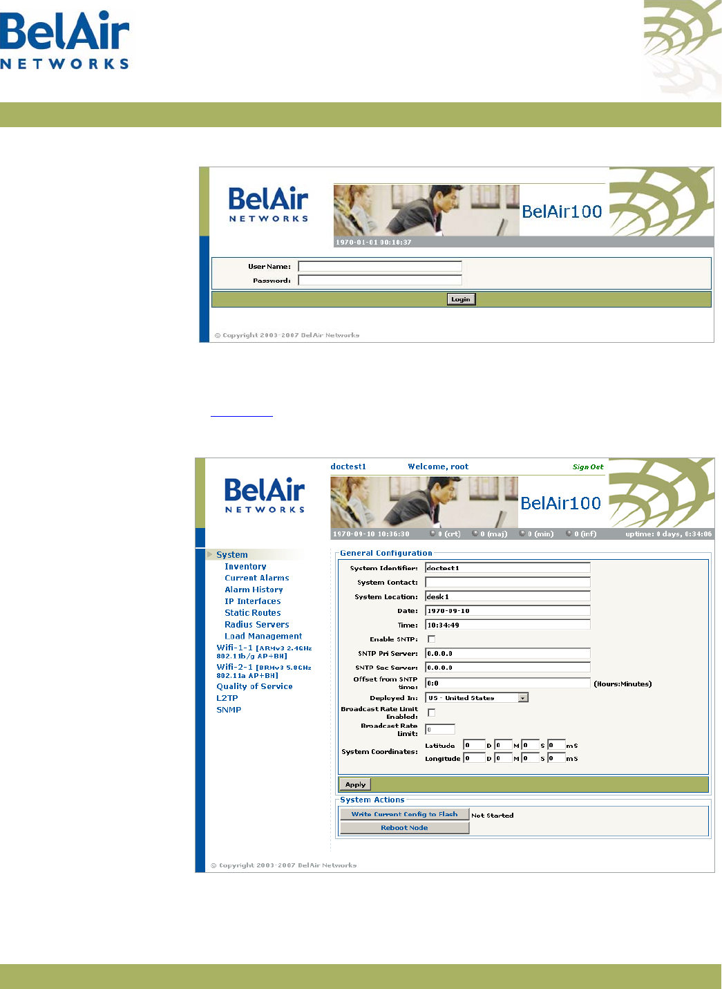
1 Open your Web browser and specify the IP address of the AP you want to
access.
The default IP address of each AP is: 10.1.1.10.
Figure 9 on page 25 shows the resulting Login page.
BELAIR-SYSTEM.mib defines basic OAM features such as software download,
temperature and BelAir Networks alarms
BELAIR-TC.mib defines BelAir Networks data types
BELAIR-TUNNEL.mib defines L2TP data types
BELAIR-WRM.mib defines BelAir Networks WiMAX data types
Table 4: BelAir Networks Enterprise MIBs (Continued)
File Name Description
BelAirOS User Guide AP Configuration Interfaces
April 22, 2012 Confidential Page 25 of 362
Document Number BDTM00000-A02 Draft
Figure 9: Typical Login Page
2 Enter a valid user name, such as root, and a valid password.
Note:The specified password is case sensitive.
Figure 10 shows a typical resulting main page for the Web interface.
Figure 10: Typical Web Interface Main Page

BelAirOS User Guide AP Configuration Interfaces
April 22, 2012 Confidential Page 26 of 362
Document Number BDTM00000-A02 Draft
Stopping a Session To stop a Web interface session, click on the Logout button located in the top
right corner each page. See Figure 10 on page 25.
Additional
Troubleshooting Tools The Web interface provides the following tools to display radio performance
metrics:
• a throughput meter
• histogram display of various performance metrics
These tools are only available with the Web interface. For full details, see “Web
Radio Troubleshooting Tools” on page 277.

BelAirOS User Guide Command Line Interface Basics
April 22, 2012 Confidential Page 27 of 362
Document Number BDTM00000-A02 Draft
Command Line Interface Basics
Use this chapter to familiarize yourself with basic CLI tasks, including:
•“Connecting to the AP” on page 27
•“Starting a CLI Session” on page 28
•“Command Modes” on page 29
•“Abbreviating Commands ” on page 33
•“Command History” on page 33
•“Special CLI Keys ” on page 34
•“Help Command” on page 34
•“Common CLI Commands” on page 38
Connecting to the
AP
You can connect to the AP default address using one of the following methods:
• through the AP radio interface
• by connecting directly to the Ethernet port on the AP
• by connecting through the cable modem, if it is equipped with one
CAUTION! Do not connect the AP to an operational data network before you configure its
desired IP network parameters. This may cause traffic disruptions due to
potentially duplicated IP addresses.
The AP must connect to an isolated LAN, or to a desktop or laptop PC
configured to communicate on the same IP sub-network as the AP.
Using the Radio Interface
Use a desktop or laptop PC equipped with a wireless 802.11a, 802.11b, 802.11g
or 802.11n compliant interface as required, configured with a static IP address
on the same subnet as the default OAM IP address (for example, 10.1.1.1/24).
For the required configuration procedure, refer to your PC and wireless
interface configuration manuals or contact your network administrator. The PC
will connect to the AP through the radio interface.
Connecting to the Ethernet Port
Use a cross-connect RJ45 cable to connect the Ethernet port of the AP.
Using the Cable Modem
The MAC address for the AP’s cable modem should have been supplied to your
System Administrator when the AP was installed so that an IP address could be

BelAirOS User Guide Command Line Interface Basics
April 22, 2012 Confidential Page 28 of 362
Document Number BDTM00000-A02 Draft
assigned to it. Contact your system administrator to determine the IP address
to use.
For a detailed procedure, refer to the AP Installation Guide.
Starting a CLI
Session
Start a Telnet or secure shell (SSH) client and connect to the AP‘s IP address. If
you are configuring the AP for the first time, you must use the default IP
address (10.1.1.10). The AP prompts you for your user name and password.
The default super-user account is “root”. The default password is “admin123”.
If the login is successful, the AP CLI prompt is displayed. The default prompt is
“#”, if you login as root. Otherwise, the default prompt string is “>”.
Note 1: The terminal session locks after four unsuccessful login attempts. To
unlock the terminal session, you must enter the super-user password.
Note 2: CLI commands are not case sensitive (uppercase and lowercase
characters are equivalent). However, some command parameters are
case sensitive. For example, passwords and any Service Set Identifier
(SSID) supplied with the
radio
commands are case sensitive. Also, all
parameters of the
syscmd
commands are case sensitive.
Note 3: Later, you will see that you can configure the AP to have more than
one interface with an IP address. For example, you can configure
Virtual LANs and management interfaces each with their own IP
address. If you do this, make sure your Telnet or secure shell (SSH)
connections are to a management interface. This ensures maximum
responsiveness for your session by keeping higher priority management
IP traffic separate from other IP traffic.

BelAirOS User Guide Command Line Interface Basics
April 22, 2012 Confidential Page 29 of 362
Document Number BDTM00000-A02 Draft
SSH Session Example of Initial Login
With secure shell, the system prompts you twice for your password.
ssh -l root 10.1.1.10
root@10.1.1.10's password:
BelAir Backhaul and Access Wireless Router
BelAir User: root
Password:
/#
Telnet Session Example of Initial Login
With Telnet, the system prompts you only once for your password.
telnet 10.1.1.10
BelAir Backhaul and Access Wireless Router
BelAir User: root
Password:
/#
Command Modes The CLI has different configuration “modes”. Different commands are available
to you, depending on the selected mode.
Each card in the AP has at least one associated physical interface. Some
examples of physical interfaces are a Wi-Fi radio or an Ethernet interface.
Use the
mode
command to display the modes that are available. Because each
physical interface and each card in the AP has its own mode, displaying the
modes also displays a profile summary of the AP. See Figure 11.

BelAirOS User Guide Command Line Interface Basics
April 22, 2012 Confidential Page 30 of 362
Document Number BDTM00000-A02 Draft
Figure 11: Sample Output of mode Command
Root Mode (/)
This is the top or root level of the CLI commands.
/# mode
/card
/htme-1
/interface
/wifi-1-1 (HTMEv1 5GHz 802.11n)
/wifi-1-2 (HTMEv1 2.4GHz 802.11n)
/eth-1-1 (1000BASE-T)
/lan-1 (1000BASE-T)
/lan-2 (1000BASE-T)
/lan-3 (1000BASE-T)
/lan-4 (1000BASE-T)
/mgmt
/protocol
/ip
/nat
/radius
/rstp
/snmp
/sntp
/te-syst (tunnel)
/qos
/services
/auto-conn
/mobility
/ssh
/ssl
/syslog
/system
/diagnostics
• The AP has one card. The HTME
card is in slot 1.
• The AP has the following physical
interfaces:
—Interface
wifi-1-1
is associated
with the HTME 5.8 GHz radio.
—Interface
wifi-1-2
is associated
with the HTME 2.4 GHz radio.
—Interface
eth-1-1
is associated with
the HTME card’s Ethernet
interface.
—Interfaces
lan-1
to
lan-4
are
associated with the HTME card’s
LAN interfaces.
• The
mgmt
mode allows you to
control user accounts, which
authentication to use, and whether
you can access the AP with Telnet.
• You can control the IP, RADIUS,
RSTP, SNMP, SNTP, L2TP and NAT
protocols through the
protocol
mode and its submodes.
• You can control auto-connect and
backhaul mobility through the
services
mode and its submodes.
• These modes allow you to control
SSH, SSL, Syslog and system settings.
You can also run diagnostics.

BelAirOS User Guide Command Line Interface Basics
April 22, 2012 Confidential Page 31 of 362
Document Number BDTM00000-A02 Draft
Card Management Mode (/card/<card_type>-<n>)
Use this mode for all hardware card management functions.
<card_type> can be one of:
•
htm
- The High Throughput Module (HTM) card is available for the BelAir20
and the BelAir100i WCS.
•
htme
- The High Throughput Module Evolved (HTME) card is available for
the BelAir20E and the BelAir20EO.
•
dru
- The Dual Radio Unit (DRU) card is available for the BelAir100N and
the BelAir100SN.
•
drue
- The Dual Radio Unit Evolved (DRUE) card is available for the
BelAir100SNE and the BelAir2100.
•
cm
- The Cable Modem (CM) card is available for the BelAir100SN and the
BelAir100SNE.
<n> is the slot number.
Physical Interfaces Mode (/interface/<iface>-<n>-<m>)
Use this mode to configure the AP‘s physical interfaces.
<iface> can be one of:
• wifi - 802.11a/b/g/n HTM, HTME, DRU or DRUE radios
• eth - 1000Base-TX, HTM, HTME, DRU or DRUE Ethernet
• lan - 1000Base-TX, HTME LAN
• bts - pico-cellular base station
<n> is the slot number where the interface is located in the AP. <n> applies
only when <iface> is
wifi
or
eth
.
<m> is port number. <m> is 1 for most interfaces. The HTM HTME, DRU and
DRUE cards can have multiple ports representing multiple Wi-Fi radios
operating different frequencies. Some configurations may have multiple
Ethernet or LAN ports.
Management Mode (/mgmt)
Use this mode to configure user accounts, user authentication and Telnet
access.

BelAirOS User Guide Command Line Interface Basics
April 22, 2012 Confidential Page 32 of 362
Document Number BDTM00000-A02 Draft
Protocol Mode (/protocol/<protocol>)
Use this mode to configure different protocols.
<protocol> can be one of:
•
ip
- IP parameters for AP and VLANs
•
nat
- Network Address Translation (NAT)
•
radius
- Remote Authentication Dial In User Service (RADIUS) user
sessions
•
rstp
- Rapid Spanning Tree Protocol (RSTP)
•
snmp
- Simple Network Management Protocol (SNMP)
•
sntp
- Simple Network Time Protocol (SNTP)
•
tr069
- TR-069 describes the CPE WAN Management Protocol (CWMP)
•
te-<eng>
- L2TP tunnel engine (te). BelAir APs can have one tunnel engine
per system (syst).
Services Mode (/services/<service>)
Use this mode to configure different services.
<service> can be one of:
•
auto-conn
- Auto-configuration
•
mobility
- Backhaul mobility
Administration Modes (/<admin>)
Use these modes for various administration tasks.
<admin> can be one of:
•
qos
- Quality of Service (QoS) parameters
•
ssh
- Secure Shell (SSH) parameters
•
ssl
- Secure Socket Layer (SSL) parameters
•
syslog
- SYSLOG messages
•
system
- System and AP configuration and administration
•
diagnostics
- Link diagnostics

BelAirOS User Guide Command Line Interface Basics
April 22, 2012 Confidential Page 33 of 362
Document Number BDTM00000-A02 Draft
Using Modes
You can move between modes with the
cd
command. For instance, you can
move from
root
mode to
system
mode using the command:
/# cd /system
/system#
Note 1: The prompt changes to match the current mode. You can further
customize the prompt to show the switch name or a 20-character
string that you define.
Note 2: Access to a mode is only allowed if the user has sufficient privileges to
execute commands in that mode.
When you access a given mode, only the commands pertaining to that mode
are available. For example, accessing
snmp
mode provides access to SNMP
commands. For a physical interface, this means that only the commands that
apply to that specific type and version of interface are available when you access
a particular physical interface. For example, if you access an HTMEv1 interface,
only the commands that apply to an HTMEv1 Wi-Fi radio are available.
Entering
?
displays the commands that apply to the currently accessed mode.
Entering
??
or
help
displays the commands that apply to the currently accessed
mode plus common commands that are available in all modes.
Users may execute commands from other modes than the current one, by
prefixing the desired command with the slash character ‘/’ followed by the
mode’s name. For instance, entering:
/system# /protocol/snmp/show community
executes a command from
snmp
mode while in
system
mode.
Abbreviating
Commands
You must enter only enough characters for the CLI to recognize the command
as unique.
The following example shows how to enter the
mgmt
mode command
show
telnet status
:
/mgmt# sh t s
Command
History
You can use the
history
command to display a list of the last commands that
you have typed.
Example
/# history

BelAirOS User Guide Command Line Interface Basics
April 22, 2012 Confidential Page 34 of 362
Document Number BDTM00000-A02 Draft
8 h
9 hi
10 ?
11 show user
12 cd /system
13 show loads
14 show sessions
15 cd /
16 cd interface/wifi-1-1/
17 ?
18 show
19 show ssid table
20 show statistics
21 history
Special CLI Keys Command Completion
You can ask the CLI to complete a partially typed command or mode name by
pressing the
tab
key. If the command or mode name cannot be completed
unambiguously, the CLI presents you with a list of possible completions. For
instance, entering:
/system# show co{tab}
produces the following output:
Available commands :
show communications
show config-download status
show coordinates
show country [detail]
Execution of the Last Typed Command
You may repeat the last command, by entering the
!
key twice, followed by
carriage return.
Executing the Previous Commands
You may browse through the command history by using the up and down arrow
keys of a VT100 or compatible terminal. You can also execute a certain
command from the command history by entering the
!
key, followed by the
command number (as displayed in the
history
command output) and carriage
return.
Help Command ?
?? [<command>]
help [<command>]

BelAirOS User Guide Command Line Interface Basics
April 22, 2012 Confidential Page 35 of 362
Document Number BDTM00000-A02 Draft
These commands display:
• a list of commands available in the current mode
• help on a particular command available in the current mode
• help on commands starting with the given keyword in the current mode
Entering "??" is equivalent to entering "help".
Available Commands
Entering
?
displays the commands that apply to the currently accessed mode.
For example:
/mgmt# ?
Available commands :
adduser <user-name> -p <passwd> [ -d <default-mode>] [-g <grp-name>]
deluser <user-name>
moduser <user-name> [ -p <passwd>] [ -d <default-mode>] [-g <grp-name>]
set authentication-login {local | radius <list>}
set telnet {enabled|disabled}
show authentication-login
show telnet status
show user
Entering
??
or
help
displays the commands that apply to the currently accessed
mode plus common commands that are available in all modes. For example:
/mgmt# ??
Available commands :
adduser <user-name> -p <passwd> [ -d <default-mode>] [-g <grp-name>]
deluser <user-name>
moduser <user-name> [ -p <passwd>] [ -d <default-mode>] [-g <grp-name>]
set authentication-login {local | radius <list>}
set telnet {enabled|disabled}
show authentication-login
show telnet status
show user
alias [<replacement string> <token to be replaced>]
cd <path>
clear-screen
console lock
exit
help [ command ]
history
mode [<mode_name>]
passwd
ping <ip addr> [-l <size>]
run script <script file> [<output file>]
version
whoami
config-save [{active|backup} remoteip <server> remotefile <filename>
[{tftp | ftp [user <username> password <password>]}]]
config-restore remoteip <ipaddress> remotefile <filename> [{tftp | ftp
[user <username> password <password>]}] [force]
show date

BelAirOS User Guide Command Line Interface Basics
April 22, 2012 Confidential Page 36 of 362
Document Number BDTM00000-A02 Draft
su <username>
Keyword Help
Entering
??
or
help
followed by a keyword displays all possible commands
starting with that keyword. For example:
/mgmt# ?? show
Available commands :
show authentication-login
Description : show authentication login status and RADIUS servers
configuration
show telnet status
Description : shows the status of the telnet.
show user
Description : List all valid users, along with their permissible mode.
show date
Description : show current system date and time
Help for a Specific Command
When help is needed for a specific command, enter
??
or
help
followed by the
command within quotes. For example:
/mgmt# help "adduser"
Available commands :
adduser <user-name> -p <passwd> [ -d <default-mode>] [-g <grp-name>]
Description : Create a user.
Help with Abbreviations
When an abbreviation is used in the help string, all matching commands are
listed with the description. For example:
/mgmt# ?? s
Available commands :
set authentication-login {local | radius <list>}
Description : defines how login session will be authenticated.
set telnet {enabled|disabled}
Description : enable or disable CLI access via the telnet protocol.
show authentication-login
Description : show authentication login status and RADIUS servers
configuration
show telnet status
Description : shows the status of the telnet.
show user
Description : List all valid users, along with their permissible mode.
show date
Description : show current system date and time
su <username>
Description : Substitute present user with the given user.

BelAirOS User Guide Command Line Interface Basics
April 22, 2012 Confidential Page 37 of 362
Document Number BDTM00000-A02 Draft
Saving your
Changes
If you change any settings from the system defaults, you must save those
changes to the configuration database to make sure they are applied the next
time the AP reboots. Similarly, you can restore the entire configuration
database from a previously saved backup copy.
Saving the Configuration
Database
config-save [{active|backup} remoteip <ipaddress>
remotefile <filename>
[{tftp|ftp [user <usrname> password <pword>]}]]
This command allows you to save the current configuration of the entire AP.
This includes all system, layer 2 and radio settings.
When used without its optional parameters, the
config-save
command saves
the configuration database for the active software load to persistent storage.
The stored configuration is automatically applied at the next reboot.
When used with its optional parameters, the
config-save
command also
transfers the configuration database to a remote server.
If
active
is specified, the
config-save
command saves the configuration database
for the active software load to persistent storage and then transfers it to a
remote server. If
backup
is specified, the configuration database for the active
software load is not saved. Instead, the configuration database for the active
software load that was saved previously to persistent storage, is transferred to
a remote server.
You can use either TFTP or FTP to communicate with the remote server. By
default, the
config-save
command uses TFTP. If you specify FTP, you can also
specify the username and password. The default FTP username is
anonymous
and the default FTP password is
root@<nodeip>
, where <nodeip> is the IP
address of AP making the request. If you do not use the default FTP username,
the FTP server must be configured to accept your username and password.
Restoring the
Configuration Database
config-restore remoteip <ipaddress> remotefile <filename>
[{tftp|ftp [user <usrname> password <pword>]}]]
[force]
This command transfers the configuration database from a remote server to
the active software load in persistent storage. This allows you to restore the
entire configuration database from a previously saved backup copy.
Use the
reboot
command for the new configuration to take effect.
You can use either TFTP or FTP to communicate with the remote server. By
default, the
config-restore
command uses TFTP. If you specify FTP, you can also
specify the user name and password. The default FTP user name is
anonymous
and the default FTP password is
root@<nodeip>
, where <nodeip> is the IP

BelAirOS User Guide Command Line Interface Basics
April 22, 2012 Confidential Page 38 of 362
Document Number BDTM00000-A02 Draft
address of AP making the request. If you do not use the default FTP username,
the FTP server must be configured to accept your username and password.
The optional
force
parameter suppresses version checking on the configuration
file that is being downloaded. You can use a backup copy that was created with
a different version of software than the current software installed on the AP. If
you do, BelAir Networks strongly recommends that you fully and thoroughly
verify the configuration and operation of the AP after you reboot the system
and before you save the restored configuration.
Example
/# cd system
/system# config-restore remoteip 122.45.6.123 remotefile unitA.conf
Common CLI
Commands
In addition to any previously described commands, the following commands are
always available, regardless of your current mode.
Terminating your CLI
Session exit
Use this command to terminate your own CLI session at any time.
Changing Your
Password
passwd
This command lets you change your current password. First, you are asked to
enter your old password. Then you must enter your new password twice, to
verify that you have typed it correctly.
Note: The specified password is case sensitive, must consist of alphanumeric
characters, must be at least six characters long, and cannot exceed 20
characters.
CAUTION! If you forget the super-user account password, you may be unable to use all the
AP’s management functions and you may need to reset the AP’s configuration to
factory defaults.
Example
passwd
Old Password:
Enter New Password:
Reenter the Password:
Password updated Successfully
Clearing the Console
Display
clear-screen
This command clears your console display window.

BelAirOS User Guide Command Line Interface Basics
April 22, 2012 Confidential Page 39 of 362
Document Number BDTM00000-A02 Draft
Locking the Console
Display
console lock
This command lock your console display window. You must enter your
password to unlock it.
Displaying the Current
Software Version
version
This command displays the version of the currently running software load.
Displaying the Current
Date and Time
show date
This command displays the current date and time.
Example 1
The following example displays the current date and time when it is set
manually.
/# show date
Current date: 2007-05-10 06:52:20
Example 2
The following example displays the current date and time when using a Simple
Network Time Protocol (SNTP) server and a time offset of -4 hours and 30
minutes. See “Configuring the System Date and Time” on page 68 for details.
/# show date
Current date: 2006-07-21 13:15:16 (UTC)
Current date: 2006-07-21 08:45:16
Displaying Current User whoami
This command displays current user.
Example
/# whoami
/# Current User is root
Switching User
Accounts
su <username>
This command changes the user account you are currently using. To return to
the original user account, use the
exit
command.
Example
/# whoami
Current User is root
/# su guest
/> whoami
Current User is guest
/> exit

BelAirOS User Guide Command Line Interface Basics
April 22, 2012 Confidential Page 40 of 362
Document Number BDTM00000-A02 Draft
/# whoami
Current User is root
Replacing a Token by a
String
alias [<replacement string> <token to be replaced>]
This command replaces the specified token by the given string. It is provided for
customers writing scripts. See “Scripting Guidelines” on page 309.
Example
/# alias gu guest
Pinging a Host or Switch ping <host> [-1 <size>]
This command pings a host machine or switch using the host name or IP
address.
The following options are supported:
-l size
specifies the size of the ping request packets to be sent.
Examples
The following example shows typical ping output:
/# ping 10.1.1.100 -l 128
PING 10.1.1.100 (10.1.1.100): 128 data bytes
136 bytes from 10.1.1.100: icmp_seq=0 ttl=128 time=2.0 ms
136 bytes from 10.1.1.100: icmp_seq=1 ttl=128 time=1.2 ms
136 bytes from 10.1.1.100: icmp_seq=2 ttl=128 time=1.0 ms
--- 10.1.1.100 ping statistics ---
3 packets transmitted, 3 packets received, 0% packet loss
round-trip min/avg/max = 1.0/1.4/2.0 ms
Starting a Telnet Session telnet <ip address> [<port_number>]
This command lets you start a Telnet session to another machine, such as
another AP, by specifying the IP address. By default t, Telnet uses port 23. You
can also specify an alternate port number.
Radio Configuration
Summary
show interface summary
This command displays a summary of the configuration of all radio interfaces.
Example
The following example shows a typical output for a BelAir20.
/# show interface summary
wifi-1-1
Radio description:............ HTMv1 5GHz 802.11n
Admin state: ................. Enabled
Channel: ..................... 149
Access:

BelAirOS User Guide Command Line Interface Basics
April 22, 2012 Confidential Page 41 of 362
Document Number BDTM00000-A02 Draft
AP admin state: ............ Enabled
Backhaul:
link admin state: .......... Enabled
link id: ................... BelAirNetworks
topology: .................. mesh
wifi-1-2
Radio description:............ HTMv1 2.4GHz 802.11n
Admin state: ................. Enabled
Channel: ..................... 6
Access:
AP admin state: ............ Enabled
Backhaul:
link admin state: .......... Disabled
link id: ................... BelAirNetworks
topology: .................. mesh

BelAirOS User Guide AP Access Methods
April 22, 2012 Confidential Page 42 of 362
Document Number BDTM00000-A02 Draft
AP Access Methods
When an AP is shipped from the factory, all access methods (CLI, SNMP, Telnet,
HTTP, HTTPS, SSH and TR-069) are enabled. You can use these interfaces to
configure the system’s IP networking parameters.
This chapter describes the CLI commands you can use to configure these
access methods.
Note: Some access methods, such as HTTP and HTTPS, are configured while
in SSL mode.
This chapter contains the following sections:
•“SNMP Configuration Guidelines” on page 42
•“SNMP Command Reference” on page 43
•“Telnet” on page 48
•“HTTP” on page 48
•“Secure HTTP” on page 48
•“SSH” on page 48
•“SSL” on page 48
•“TR-069” on page 50
SNMP
Configuration
Guidelines
This section describes how to configure the AP to communicate to either an
SNMPv1/v2 server or an SNMPv3 server.
SNMPv1/v2 Servers To configure an SNMP community, use the
set community
command described
in “Communities” on page 44.
For sending traps, use the
set trap
command described in “Traps” on page 45
to configure the AP with the parameters of the destination SNMP manager.
Refer to “SNMP Command Reference” on page 43 for detailed descriptions of
all SNMP commands.
SNMPv3 Servers To configure an SNMP user, use the
set user
command described in “Users” on
page 45.

BelAirOS User Guide AP Access Methods
April 22, 2012 Confidential Page 43 of 362
Document Number BDTM00000-A02 Draft
For sending notifications, use the
set notify
command described in
“Notifications” on page 46 to configure the AP with the parameters of the
destination SNMP manager.
Refer to “SNMP Command Reference” on page 43 for detailed descriptions of
all SNMP commands, including entities that need to be predefined.
SNMP Naming
Restrictions SNMP community names, user names, and notification names must not contain
the following characters:
—bar (|)
—semicolon (;)
—percent (%)
—double quotation mark (“)
SNMP Command
Reference
The following sections show you how to configure SNMP functions.
SNMP Agent /protocol/snmp/set snmp-agent {enabled | disabled}
/protocol/snmp/show snmp-agent
The
set snmp-agent
command enables or disables SNMP access.
SNMP Configuration /protocol/snmp/show config [{v2 | v3 | all}]
Use the
show config
command to display the current SNMP configuration.
Passwords are only displayed to users with
root
privileges. See “User Privilege
Levels” on page 52 for details.
Example 1
/protocol/snmp# show config v2
EngineId: 80003d9805000d67091448
Community configuration:
------------------------
Index Name IP Address Privilege
----- ------------------ --------------- -----------
1 public 0.0.0.0 ReadOnly
2 private 10.1.1.70 ReadWrite
Trap configuration:
-------------------
Index IP address Community Version

BelAirOS User Guide AP Access Methods
April 22, 2012 Confidential Page 44 of 362
Document Number BDTM00000-A02 Draft
----- --------------- --------------- -------
1 10.1.1.70 public v1v2
Example 2
/protocol/snmp# show config v3
EngineId: 80003d9805000d67006902
User configuration:
-------------------
User Name IP address Auth Password Privacy Password Privilege
------------------------- --------------- ---- --------------- -------- --------------- ---------
Test 0.0.0.0 MD5 md5md5md5 DES_CBC TEST ReadWrite
Notification configuration:
-------------------
Name Type IP address Timeout Retry Auth Password Privacy Password
--------------- ------ --------------- ------- ----- ---- --------------- ------- ---------
TRAP trap 10.1.1.70 1250 2 MD5 md5md5md5 DES_CBC TRAP
Communities /protocol/snmp/set community <CommunityIndex>
community-name <name> ipaddr <ip_addr>
privilege {readonly|readwrite}
/protocol/snmp/delete community <CommunityIndex>
/protocol/snmp/show community
The
set community
command configures the SNMP community security. You
can configure up to 10 communities. The community is assigned with privileges.
The
delete community
command deletes the specific community information.
The
show
command displays the SNMP community configuration.
Assigning an IP address of 0.0.0.0 to an SNMP community of an AP allows AP
access by all managers configured for that community. See “Example 1” on
page 44. To limit access to a single manager, enter the manager’s IP address. See
“Example 2” on page 44.
Example 1
/protocol/snmp# set community 1 community-name belair ipaddr 0.0.0.0 privilege readonly
In this example, all managers configured with the SNMP community of
belair
can access the AP for read only functions.
Example 2
/protocol/snmp# set community 1 community-name belair200 ipaddr 10.10.10.11 privilege readonly
/protocol/snmp# set community 2 community-name belair100 ipaddr 20.20.20.20 privilege readwrite
/protocol/snmp# set community 3 community-name belcom ipaddr 30.30.30.30 privilege readonly
In the previous example, the manager at IP address 20.20.20.20 configured with
the SNMP community of
belair100
has read-write access to the AP.

BelAirOS User Guide AP Access Methods
April 22, 2012 Confidential Page 45 of 362
Document Number BDTM00000-A02 Draft
Example 3
/protocol/snmp# show community
Index Name IP Address Privilege
----- ------------------ --------------- -----------
1 public 0.0.0.0 ReadOnly
2 private 10.1.1.70 ReadWrite
Trap s /protocol/snmp/set trap <index> mgr-addr <ip_addr>
community <name> version {v1|v2|both}
/protocol/snmp/delete trap <index>
/protocol/snmp/show trap
The
set trap
command configures the parameters of the SNMPv2 trap manager.
You can configure up to 10 traps.
The
delete trap
command deletes the specified trap manager information.
The
show trap
command displays the SNMPv2 trap manager configuration
information.
Example 1
/protocol/snmp# set trap 1 mgr-addr 40.40.40.40 community bel1 version v1
/protocol/snmp# set trap 2 mgr-addr 41.41.41.41 community bel2 version v2
Example 2
/protocol/snmp# show trap
Index IP address Community Version
----- --------------- --------------- -------
1 10.1.1.70 public v1v2
Users /protocol/snmp/set user <UserName> ipaddr <IP_addr>
access {readonly | readwrite}
[auth {md5 | sha} <password> [priv-DES <passwd>]]
/protocol/snmp/delete user <UserName>
/protocol/snmp/show user
The
set user
command defines an SNMPv3 user. You can define up to 10 users,
each with different authentication and privacy settings.
The
ipaddr
parameter specifies the IP address associated with this user. The
access
parameter specifies the level of access granted to this user.
The
<password>
parameter is the password required by the user to access
SNMP data. A user must supply this password if using a MIB browser.
The AP uses DES encryption to encrypt SNMP packets. The
priv-DES
parameter specifies the encryption key required to encrypt or decrypt the
packet.

BelAirOS User Guide AP Access Methods
April 22, 2012 Confidential Page 46 of 362
Document Number BDTM00000-A02 Draft
The
delete user
command deletes the definition of the specified SNMP user.
The
show
command displays the configured users. Passwords are only displayed
to users with
root
privileges. See “User Privilege Levels” on page 52 for details.
Example 1
/protocol/snmp# set user v3md5 ipaddr 0.0.0.0 access readwrite auth md5 md5md5md5
Example 2
/protocol/snmp# show user
User Name IP address Auth Password Privacy Password Privilege
-------------- --------------- ---- --------------- -------- ---------
v3md5 0.0.0.0 MD5 md5md5md5 None none ReadWrite
Notifications /protocol/snmp/set notify <NotifyName> type {Trap | Inform}
ipaddr <IP_addr> [timeout <1-1500>]
[retries <1-3>] [auth {md5 | sha}
<password> [priv-DES <passwd>]]
/protocol/snmp/delete notify <NotifyName>
/protocol/snmp/show notify
The
set notify
command enables notifications to be sent to an SNMPv3
manager for the specified notification name. You can configure up to
10 notification names.
The
ipaddr
parameter specifies the IP address associated with this notification.
The
timeout
parameter specifies how many seconds to wait for an
acknowledgement before resending the SNMP packet. The
retries
parameter
specifies the number of times to resend the SNMP before declaring a failure.
The
<password>
parameter is the password associated with this notification.
The AP uses DES encryption to encrypt SNMP packets. The
priv-DES
parameter specifies the encryption key required to encrypt or decrypt the
packet.
The
delete notify
command disables notifications from being sent for the
specified notification name.
The
show notify
command displays the current SNMP notify configuration.
Passwords are only displayed to users with
root
privileges. See “User Privilege
Levels” on page 52 for details.
Example 1
/protocol/snmp# set notify trap1 type trap ipaddr 10.1.1.70

BelAirOS User Guide AP Access Methods
April 22, 2012 Confidential Page 47 of 362
Document Number BDTM00000-A02 Draft
Example 2
/protocol/snmp# show notify
Name Type IP address Timeout Retry Auth Password Privacy Password
--------------- ------ -------------- ------- ----- ---- --------------- ------- -------------
trap1 trap 10.1.1.70 1500 3 None none None none
trap2 trap 10.1.1.70 1250 3 None none None none
trap3 trap 10.1.1.70 1250 2 None none None none
trap4 trap 10.1.1.69 1500 3 SHA shasha None none
trap5 trap 10.1.1.69 1500 3 MD5 md5md5 None none
trap6 trap 10.1.1.11 1500 3 None none None none
trap7 trap 10.1.1.12 1250 3 None none None none
trap8 trap 10.1.1.12 1250 3 MD5 md5md5 DES_CBC JEKTEST
trap9 trap 10.1.1.9 1250 3 MD5 md5md5 DES_CBC bob
trap10 trap 10.1.1.8 50 1 MD5 md5md5 DES_CBC bob
Authentication Traps /protocol/snmp/set authentication-trap {enable|disable}
/protocol/snmp/show authentication-trap status
These commands enable or disable the ability to send authentication traps.
Engine Identifier /protocol/snmp/show engineid
This command displays the current engine identifier.
SNMP Statistics /protocol/snmp/show statistics
This command displays SNMP statistics.
Example 1
/protocol/snmp# show statistics
Packets In: 0
Bad SNMP Version errors: 0
Unknown community name: 0
Set on read-only: 0
Get request PDUs: 0
Get Next PDUs: 0
Set request PDUs: 0
Packets Out: 0
Too big errors: 0
No such name errors: 0
Bad value errors: 0
General errors: 0
Trap PDUs: 7
Drops: 0
Informs:
Requests generated: 0
Responses received: 0
Messages Dropped: 0
Requests awaiting Ack: 0

BelAirOS User Guide AP Access Methods
April 22, 2012 Confidential Page 48 of 362
Document Number BDTM00000-A02 Draft
USM:
Decryption errors: 0
Unknown user name: 0
Unknown engine ID: 0
Invalid security level: 0
Te l n e t /mgmt/telnet {enable|disable}
/mgmt/show telnet status
The
telnet
command enables or disables Telnet access to the AP.
The
show
command displays the status of the Telnet interface.
Example 1
/#cd /mgmt/
/mgmt# telnet enable
Example 2
cd /mgmt/
/mgmt# show telnet status
Telnet: Enabled
HTTP /ssl/set http {enable|disable}
/ssl/show http status
These commands enable or display the HTTP interface. The
show
command
displays the current status.
Secure HTTP /ssl/set secure-http {enable|disable}
/ssl/show secure-http status
These commands enable or display the secure HTTP interface. The
show
command displays the current status.
SSH The following sections show you how to configure the Secure Shell (SSH)
functions.
SSH Access /ssh/show ssh status
This command displays the status of the SSH interface.
SSL The following sections show you how to configure the Secure Socket Layer
(SSL) functions.
Displaying Server
Certificate
/show ssl server-cert
This command displays the server-certificate for SSL.

BelAirOS User Guide AP Access Methods
April 22, 2012 Confidential Page 49 of 362
Document Number BDTM00000-A02 Draft
Configuring the Server
Certificate To configure the server certificate:
1 Create the RSA key pair. See “Creating RSA Key Pair” on page 49.
2 Create a certificate request. See “Creating Certificate Request” on page 49.
The certificate request is displayed on the screen.
3 Copy the certificate request to a file and send it to the Certificate Authority
(CA) that will generate the certificate.
4 When the CA responds with the certificate, configure the AP SSL
configuration to use it. See “Configuring the Server Certificate” on page 49.
5 Save the SSL configuration. See “Saving an SSL Configuration” on page 49.
Creating RSA Key Pair /ssl/ssl gen key {rsa} <no. of bits>
This command creates a new RSA key pair. The input value of
no of bits
can be
512 or 1024.
Example
/#cd ssl
/ssl# ssl gen key rsa 1024
Creating Certificate
Request
/ssl/ssl gen cert-req algo rsa sn <SubjectName>
This command creates a certificate request using the RSA key pair and
SubjectName
. The subject name is the identification of the switch or the
switch’s IP address.
Example
/#cd ssl
/ssl# ssl gen cert-req algo rsa sn 10.1.1.10
Configuring the Server
Certificate
/ssl/ssl server-cert
This command imports a server certificate provided by a CA.
When you use this command, you are prompted to enter the certificate. To do
so, open the certificate and copy its contents to the CLI.
Note: The application that you use to open the certificate may insert
additional line breaks and spaces at the end of each line of the
certificate. Make sure to remove these extra line breaks and spaces
when you copy the certificate to the CLI.
Saving an SSL
Configuration
/ssl/ssl save
This command saves the SSL configuration.

BelAirOS User Guide AP Access Methods
April 22, 2012 Confidential Page 50 of 362
Document Number BDTM00000-A02 Draft
Example
/#cd ssl
/ssl# ssl save
TR-069 TR-069 describes the CPE WAN Management Protocol (CWMP) required for
communications between a CPE device, such as a BelAir Networks AP, and an
Auto-configuration Server (ACS).
This section describes how to configure the AP to communicate with an ACS.
Only the following BelAir Networks APs support TR-069: BelAir20, BelAir100i
WCS, BelAir100N, BelAir100SN, BelAir100SNE and BelAir2100.
Configuring ACS
Communications
/protocol/tr069/set acs-configuration url <hostname>
user <username> password <password>
/protocol/tr069/set inform {enabled ([interval <seconds>])
|disabled}
/protocol/tr069/set cpe-configuration url <hostname>
user <username>
password <password>
[port <1024-65535>]
/protocol/tr069/set dos-attack {requests <1-1000>
interval <1-900>}
/protocol/tr069/set state {enabled | disabled}
/protocol/tr069/show config
The
set acs-configuration
command specifies the ACS to communicate with:
• The
url
parameter specifies the host for the ACS. The default value is
http://211.110.60.3:8080/TMS/acs
.
• The
user
parameter specifies the user name to login to the ACS. The default
value is
tmsadmin
.
• The
password
parameter specifies the password to login to the ACS. The
default value is
tmsadmin123
.
The
set inform
command specifies how often the AP sends
inform
messages to
the ACS. The
interval
parameter ranges from 60 to 900 seconds. By default,
inform
messages are sent every 300 seconds.
The
set cpe-configuration
command specifies the parameters by which the ACS
can log into the CPE device, such as the BelAir Networks AP:
• The
url
parameter specifies the DNS or IP address to reach the CPE device.
• The
user
parameter specifies the user name to login to the CPE device. The
default value is
admin
.
• The
password
parameter specifies the password to login to the CPE device.
The default value is
password
.

BelAirOS User Guide AP Access Methods
April 22, 2012 Confidential Page 51 of 362
Document Number BDTM00000-A02 Draft
• The optional
port
parameter allows you to use a particular port to
communicate with the CPE device. The default value is 7788.
The
set state
command enables or disables ACS communications. By default,
ACS communications are disabled.
The
show config
command displays the current TR-069 configuration.
Example
/protocol/tr069# show config
ACS Configuration
=================
URL : http://172.16.1.166:8082
User : tms
Password : tms
Inform : Enabled
Interval : 300 secs
CPE Configuration
=================
URL : http://10.1.1.10:7788
User : admin
Password : password
DoS : 10 requests in 10 secs

BelAirOS User Guide User and Session Administration
April 22, 2012 Confidential Page 52 of 362
Document Number BDTM00000-A02 Draft
User and Session Administration
This chapter describes user administration functions with the following topics:
•“User Privilege Levels” on page 52
•“User Accounts” on page 55
•“Configuring Authentication for User Accounts” on page 56
•“CLI and Web Sessions” on page 58
User Privilege
Levels
User accounts on an AP can be assigned the following three privilege levels:
•An
observer
user can execute only the following commands:
—most
show
commands
—the
help
and
?
commands
—the
passwd
command
—the
clear-screen
and
exit
commands
—the
cd
and
mode
commands
—the
history
command
—the
whoami
command
—the
ping
command
•A
normal
user can execute any CLI command, except those reserved for
the super-user.
• The
super-user
can execute any CLI command. Table 5 on page 52 lists the
CLI commands that are reserved for the super-user.
Each AP can have any number of observer users and normal users, but only one
super-user account, called
root
.
Table 5: Super-user commands
Common Commands
config-restore remoteip <ipaddress> remotefile <filename>
[{tftp|ftp [user <usrname> password <pword>]}]]
[force]

BelAirOS User Guide User and Session Administration
April 22, 2012 Confidential Page 53 of 362
Document Number BDTM00000-A02 Draft
Mgmt Commands
adduser <user-name> -p <passwd> [-d <mode>] [-g <group>]
deluser <user-name>
moduser <user-name> [ -p <passwd>] [ -d <mode>] [-g <group>]
show user
set telnet {enabled|disabled}
set authentication-login {local | radius <list>}
show authentication-login
System Commands
set country <country_name>
set global-session-timeout <period>
terminate session <session_index>
upgrade load remoteip <serverIPaddress>
remotepath <serverSubDir>
[{tftp|ftp [user <usrname> password <pword>]}]]
cancel upgrade
reboot [{force}]
commit load
set next-load {A|B|current|inactive}
syscmd restoreDefaultConfig
/Card/<card_type>-n Commands
reboot [{force}]
/Protocol/IP Commands
set interface {system | vlan <vlan_id>}
static <ip addr> <mask>
[delay-activation]
set interface {system | vlan <vlan_id>} dynamic
fallback-ip <address> <mask>
accept-dhcp-params {enabled|disabled}
[delay-activation]
Table 5: Super-user commands (Continued)

BelAirOS User Guide User and Session Administration
April 22, 2012 Confidential Page 54 of 362
Document Number BDTM00000-A02 Draft
renew ip {system | vlan <vlan_id>}
SSL Mode Commands
set http {enable|disable}
set secure-http {enable|disable}
show http status
show secure-http status
show server-cert
ssl gen cert-req algo rsa sn <SubjectName>
ssl gen key {rsa} <no. of bits>
ssl save
ssl server-cert
Syslog Mode Commands
logserver {enable [<ip address>] | disable}
monitor logging {enable | disable}
loglevel {debug|info|notice|warn|error|critical|alert|emerg}
/Protocol/SNMP Mode Commands
set snmp-agent {enabled | disabled}
set community <CommunityIndex>
community-name <name> ipaddr <ip_addr>
privilege {readonly|readwrite}
delete community <CommunityIndex>
set trap <index> mgr-addr <ip_addr>
community <name> version {v1|v2|both}
delete trap <index>
set user <UserName> ipaddr <IP_addr>
access {readonly | readwrite}
[auth {md5 | sha} <password> [priv-DES <passwd>]]
delete user <UserName>
Table 5: Super-user commands (Continued)

BelAirOS User Guide User and Session Administration
April 22, 2012 Confidential Page 55 of 362
Document Number BDTM00000-A02 Draft
User Accounts /mgmt/adduser <user-name> -p <passwd> [-d <mode>] [-g <group>]
/mgmt/deluser <user-name>
/mgmt/moduser <user-name> [-p <passwd>] [-d <mode>] [-g <group>]
/mgmt/show user
The
adduser
command creates a new user account.
The
deluser
command deletes a user account. The default login, “root”, cannot
be deleted.
The
moduser
command modifies the parameters of a user account. For this
command, the
group
parameter does not apply to changes to the
root
account.
The
show user
command lists all valid user accounts, the mode in which they
start their session and their maximum privilege level. For example, under
Groups,
normal users display
NORMAL OBSERVER
while the
root
account
displays
root NORMAL OBSERVER
.
The
mode
parameter sets the command mode that a user accesses when they
log in. If unspecified, it defaults to a slash (/) so the user begins their session in
root mode. Users with observer privileges must start their sessions in root
mode.
The
group
parameter specifies the user account’s privilege level. It can be
OBSERVER
or
NORMAL
. If unspecified, the user account has observer
privileges.
To use this command, you must be in
mgmt
mode.
Note 1: The specified password is case sensitive, must consist of alphanumeric
characters, must be at least six characters long, and cannot exceed 20
characters. Changes the super-user account require that you provide
the super-user password.
Note 2: The specified group is case sensitive.
If you use a RADIUS server to authenticate users as they login, you must
specify the user’s privilege level in the RADIUS
Reply-Message
field. Specifically,
set notify <NotifyName> type {Trap | Inform}
ipaddr <IP_addr> [timeout <1-1500>]
[retries <1-3>] [auth {md5 | sha}
<password> [priv-DES <passwd>]]
delete notify <NotifyName>
set authentication-trap {enable | disable}
Table 5: Super-user commands (Continued)

BelAirOS User Guide User and Session Administration
April 22, 2012 Confidential Page 56 of 362
Document Number BDTM00000-A02 Draft
the
Reply-Message
field must contain in plain text one of the following:
root
,
NORMAL
or
OBSERVER
. These entries in RADIUS are case sensitive, so make
sure the user privilege levels are entered exactly as specified. If the privilege
levels are unspecified in RADIUS, then the AP provides the user with
observer
privileges.
Example 1
/mgmt# adduser testuser -p userpwd - d system
Example 2
/mgmt# deluser xyz
Example 3
In the following example, the user
guest
begins their session in
interface
mode
and their password is changed to “guest123”.
/mgmt# moduser guest –p guest123 –d interface
Example 4
/mgmt# show user
USER MODE GROUPS
root / root NORMAL OBSERVER
user1 / OBSERVER
user2 / OBSERVER
user3 interface NORMAL OBSERVER
Configuring
Authentication
for User
Accounts
You can use a RADIUS server to authenticate users as they login to their
accounts. This applies to all user accounts including
root
.
Authentication Mode /mgmt/set authentication-login {local|radius <list>}
/mgmt/show authentication-login
These commands determine how the AP authenticates users.
The
local
setting means that the AP uses the locally stored password and user
account information to authenticate the user. This is the default setting.
The
radius
setting means that the AP uses a RADIUS server to authenticate the
user. The
list
parameter specifies the index used in the RADIUS server list.
Refer to “RADIUS Servers” on page 57.

BelAirOS User Guide User and Session Administration
April 22, 2012 Confidential Page 57 of 362
Document Number BDTM00000-A02 Draft
Example 1
/mgmt# set authentication-login radius 1,2
Example 2
mgmt# show authentication-login
Authentication Login is radius
Radius Authentication server table
-------------------------------------
Index : 1
Radius Server Address : 10.1.3.254
UDP port number : 1812
Radius Client Address : 10.1.3.48
Timeout : 3
--------------------------------------------
Index : 2
Radius Server Address : 10.1.3.253
UDP port number : 1812
Radius Client Address : 10.1.3.48
Timeout : 3
--------------------------------------------
RADIUS Servers /protocol/radius/set server <server-idx> <IP_addr>
<shared-secret>
[authport <server-port>]
[acctport <acct-port>]
[interface {system | vlan <vlan_id>}]
[timeout <seconds>]
[reauthtime <seconds>]
/protocol/radius/set server-state <server-idx> {enabled|disabled}
/protocol/radius/del server <server-idx>
/protocol/radius/show servers
These commands allow you to specify a list of RADIUS servers that you can use
to authenticate users. The list can contain up to 10 servers.
The
IP_addr
parameter specifies the IP address of the RADIUS server.
The
shared-secret
parameter specifies the password for access to the RADIUS
server.
The
authport
parameter ranges from 0 to 65535. It specifies the UDP port
number of the RADIUS server (typically 1812).
The
acctport
parameter ranges from 0 to 65535. It specifies the UDP port
number for RADIUS accounting data (typically 1813).
The
interface
parameter specifies the interface to associate the AP RADIUS
client to. This can be the AP’s system interface or any VLAN interface. The
vlan_id
parameter ranges from 1 to 3015 and from 3018 to 4045. The default
value is
system
.

BelAirOS User Guide User and Session Administration
April 22, 2012 Confidential Page 58 of 362
Document Number BDTM00000-A02 Draft
The
timeout
parameter ranges from 2 to 300. It specifies the interval (in
seconds) after which the RADIUS client considers that the remote server has
timed out if a reply is not received. The default value is 10 seconds.
The
reauthtime
parameter ranges from 0 to 50000000. It specifies the RADIUS
re-authentication time (in seconds). This forces the AP to check all connected
clients with the RADIUS server (that is, make sure they are still allowed to
access the network) at the specified interval. You only need to configure this
parameter if it is not specified on the RADIUS server. Setting the interval to
zero disables this feature. The maximum interval time is 2147483647. If you
enter a higher number, the value is set to its maximum.
Note: Make sure the user’s privilege level are correctly specified in the
RADIUS
Reply-Message
field. Refer to “User Accounts” on page 55.
Example 1
/protocol/radius# set server 3 172.16.1.20 my-secret12345 authport 1812 acctport 1813 interface
system timeout 15 reauthtime 1
Example 2
/protocol/radius# set server-state 3 enabled
CLI and Web
Sessions
The AP allows you to manage CLI and Web session, such as listing and
terminating sessions as well as configuring the idle timeout period.
Session Management /system/show sessions
/system/terminate session <session_index>
The
show sessions
command lists all active CLI and Web interface sessions.
The current session is flagged with an asterisk besides its session index number.
The
terminate session
command allows you to terminate any CLI or Web
session.
Example
/system# show sessions
index user type IP address since last-cmd timeout tssh logging
----- -------- ------- --------------- --------- --------- --------- --------- ---------
1 root telnet 10.9.9.14 0:27:57 0:01:43 0:30:00 inactive active
9 root telnet 10.9.9.14 0:22:09 0:00:00 0:30:00 inactive active
11[*] root web 10.9.9.14 0:13:51 0:13:51 1:00:00
In this example, the current session is session 11 with an idle period set at
1hour.

BelAirOS User Guide User and Session Administration
April 22, 2012 Confidential Page 59 of 362
Document Number BDTM00000-A02 Draft
Configuring the Session
Timeout Interval
/system/set global-session-timeout <period>
/system/set session-timeout <period>
/system/show global-session-timeout
By default, a CLI session is automatically disconnected if it is idle for longer than
30 minutes. These commands allows you to change the idle period, preventing
unwanted disconnections. The idle period is specified in minutes. Setting a
period of 0 prevents any automatic disconnection.
The
set global-session-timeout
command changes the idle period of all CLI
sessions. Its <period> parameter ranges from 1 to 1440; that is up to 24 hours.
You cannot specify 0 as the global session idle period. You must be logged in as
root
to use this command.
The
set session-timeout
command changes the idle period of only the current
CLI sessions. Its <period> parameter ranges from 0 to 1440; that is up to
24 hours. The session timeout period overrides the global timeout period.
The new idle period takes effect immediately and to all current and future
sessions; until changed with these commands again.
The
show
command displays the settings for the global timeout period. To see
the setting for the session, use the
/system/show sessions
command.
Example
/system# set idle-timeout 60
CLI Prompt
Customization
/system/set prompt selection [default|string|switch-name}
/system/set prompt string <20-char_string>
/system/show prompt
The
set prompt selection
command customizes the prompt for CLI sessions.
The choices are as follows:
•
default
, where the CLI prompt includes the current command mode only
•
switch-name
, where the CLI prompt includes the current command mode
and the first eight characters of the switch name described in “System
Identification Parameters” on page 67
•
string
, where the CLI prompt includes the current command mode and the
20-character string as defined by the
set prompt string
command. The string
can consist of any 20 ASCII characters, except for the semicolon (;).
The
show prompt
command displays the current prompt settings.

BelAirOS User Guide User and Session Administration
April 22, 2012 Confidential Page 60 of 362
Document Number BDTM00000-A02 Draft
Examples
/system#set prompt string BelAir-128-50-46-189
/system#set prompt selection string
[BelAir-128-50-46-189]/system#system switch BA20E-A
[BelAir-128-50-46-189]/system#set prompt selection switch-name
[BA20E-A]/system#set prompt selection switch-name
[BA20E-A]/system#set prompt selection default
/system# show prompt
User-defined string: BelAir-128-50-46-189
prompt selection: default

BelAirOS User Guide IP Settings
April 22, 2012 Confidential Page 61 of 362
Document Number BDTM00000-A02 Draft
IP Settings
This chapter contains procedures for managing AP IP parameters as follows:
•“Displaying IP Parameters” on page 61
•“Configuring IP Parameters” on page 62
—“Configuring Dynamic IP Addressing” on page 62
—“Renewing the IP Address” on page 63
—“Auto-IP” on page 63
—“Setting a Static IP Address and Subnet Mask” on page 64
—“Static IP Routes” on page 64
•“Configuring the Domain Name System Lookup Service” on page 65
•“Configuring IP Address Notification” on page 65
CAUTION! The AP uses internal IP addresses in the range of 192.168.1.x, 192.168.2.x and
192.168.3.x. As a result, do not configure the AP to use any IP addresses within
these ranges.
Displaying IP
Parameters
/protocol/ip/show config
The
/protocol/ip/show config
command displays a detailed view of the system’s
IP configuration.
Example
/protocol/ip# show config
Interfaces:
Address Configured/ Configured/ Accept
Current Current Alloc Fallback Fallback DHCP
Interface Address Netmask Type D Address Netmask Parameters
------------------------------------------------------------------------------------------------
System 10.9.9.20 255.255.255.0 Static 10.9.9.20 255.255.255.0 Disabled
AutoIP: Enabled
Routes:
Destination Netmask Gateway Interface Active
--------------- --------------- --------------- ------------------ ------
No static routes currently configured
DNS:
Domain name lookup: disabled
Configured domain name:

BelAirOS User Guide IP Settings
April 22, 2012 Confidential Page 62 of 362
Document Number BDTM00000-A02 Draft
Configured primary DNS server: 0.0.0.0
Configured secondary DNS server: 0.0.0.0
Configuring IP
Parameters
You can configure:
• dynamic IP addressing
• a static IP address and subnet mask, as well as static IP routes.
Configuring Dynamic IP
Addressing
/protocol/ip/set interface {system | vlan <vlan_id>} dynamic
fallback-ip <address> <mask>
accept-dhcp-params {enabled|disabled}
[delay-activation]
/protocol/ip/del ip vlan <vlan_id>
The
set interface
command specifies that a Dynamic Host Configuration
Protocol (DHCP) server provides IP addresses for the AP. This includes IP
addresses for the AP’s management interface as well as any VLANs it may have.
If you specify a new VLAN, then that VLAN is created. The
del ip vlan
command deletes VLAN IP parameters previously created with the
set
interface
command.
The
vlan_id
parameter ranges from 1 to 3015 and from 3018 to 4045.
If the IP address is dynamically set, BelAir Networks recommends that you also
configure the
switch name
,
location
and
contact
parameters. These parameters
then allow you to identify the AP if you later need to do a remote CLI session.
Refer to “System Identification Parameters” on page 67.
In addition to providing the IP address, the DHCP server can be used to supply
additional parameters including:
• a TFTP server and a script file name
• DNS server IP address and a domain name
• a SNTP server list and time offset
The
accept-dhcp-params
parameter controls whether the AP accepts additional
parameters from the DHCP server or not. Refer to “DHCP Options” on
page 78 for details.
The
delay-activation
parameter specifies that the new IP parameters do not
take effect until after you execute a
config-save
command. BelAir Networks
recommends that you always specify
delay-activation
if you change the system
IP parameters. Otherwise you will need to start a new CLI session using the
new IP address to execute the
config-save
command to save your changes.

BelAirOS User Guide IP Settings
April 22, 2012 Confidential Page 63 of 362
Document Number BDTM00000-A02 Draft
Note 1: DHCP servers usually have the ability to assign a default route to
DHCP clients. Make sure that the DHCP server assigns only one
default route, even you are using many different IP interfaces on the
same AP (for example, a management IP interface and a VLAN IP
interface).
Note 2: You must configure the DHCP server lease time to be one minute or
longer.
Note 3: If the network contains APs with static IP addressing and APs with
dynamic IP addressing, make sure the DHCP server does not issue
addresses that been previously issued statically.
Example
/protocol/ip# set interface system dynamic fallback-ip 92.121.68.34
255.255.255.255 accept-dhcp-params disabled delay-activation
The previous command changes the system interface to:
• accept a dynamic IP address, and no other parameters, from a DHCP server
• if the DHCP server cannot be reached, use an IP address of 92.121.68.34
and an IP mask of 255.255.255.255
The changes do not take effect until you use the
config-save
command to save
your changes.
Renewing the IP
Address
/protocol/ip/renew ip {system | vlan <vlan_id>}
This command is used when the AP is configured to dynamically receive IP
addresses. See “Configuring Dynamic IP Addressing” on page 62.
Issuing this command causes the DHCP server to renew the IP address of the
AP’s management interface or of the VLAN. The
vlan_id
parameter ranges
from 1 to 3015 and from 3018 to 4045.
CAUTION! Using this command may cause the DHCP server to change the IP address of
the AP’s management interface. If this happens you may need to reconnect to
the AP using the new IP address.
Auto-IP /protocol/ip/set auto-IP {enabled | disabled}
This command lets you configure the auto-IP feature which complements the
fallback IP when you configure dynamic IP addressing. Auto-IP is useful when
multiple APs have been configured with the same fallback IP.

BelAirOS User Guide IP Settings
April 22, 2012 Confidential Page 64 of 362
Document Number BDTM00000-A02 Draft
The auto-IP feature automatically configures the AP to have a specific default IP
address based on the AP’s MAC address if it cannot get an IP address from the
DHCP server or when it is in factory default mode.
When auto-IP is enabled, the default IP address is
169.254.1.x
with a mask of
255.255.0.0
; where
x
is the last byte of the AP’s MAC address. When you can
connect a laptop directly to the AP, the laptop also auto-configures itself with
an IP address 169.254.x.x and a mask of 255.255.0.0 if it is in DHCP mode. You
can then use the laptop to start a CLI session into the AP with its 169.254.1.x
address.
The default setting is
enabled
.
Setting a Static IP
Address and Subnet
Mask
/protocol/ip/set interface {system | vlan <vlan_id>}
static <ip addr> <mask>
[delay-activation]
/protocol/ip/del ip vlan <vlan_id>
The
set interface
command specifies that the AP uses static IP addressing for
the AP’s management interface as well as any VLANs it may have. If you specify
a new VLAN, then that VLAN is created. The
vlan_id
parameter ranges from 1
to 3015 and from 3018 to 4045. The
del ip vlan
command deletes VLAN IP
parameters previously created with the
set interface
command.
The
delay-activation
parameter specifies that the new IP parameters do not
take effect until after you execute do a
config-save
command. BelAir Networks
recommends that you always specify
delay-activation
if you change the system
IP parameters. Otherwise you will need to start a new CLI session using the
new IP address to execute the
config-save
command to save your changes.
Example
/protocol/ip# set interface system static 92.121.68.34 255.255.255.255
delay-activation
The previous command changes the system interface to have a static IP address
of 92.121.68.34 and an IP mask of 255.255.255.255. The changes do not take
effect until you use the
config-save
command to save your changes.
Static IP Routes /protocol/ip/add route <dest ip addr> <dest mask> gw <gateway>
/protocol/ip/del route <dest ip addr> <dest mask> gw <gateway>
The
ip route add
command adds extra static IP routes. If your APs needs to
communicate with an IP interface from another sub-network, you must add the
appropriate routes to the remote IP interface. Contact your administrator to
obtain the IP address and mask of the remote IP interface.

BelAirOS User Guide IP Settings
April 22, 2012 Confidential Page 65 of 362
Document Number BDTM00000-A02 Draft
The
ip route del
command deletes a static route.
Use the
gateway
parameter to specify the IP address of the network gateway.
Configuring the
Domain Name
System Lookup
Service
/protocol/ip/set dns server {primary | secondary} <ip_address>
/protocol/ip/del dns server {primary | secondary}
/protocol/ip/set dns domain name <customer.com>
/protocol/ip/del dns domain name
The AP provides a Domain Name System (DNS) lookup service by providing a
DNS client that resolves computer names to IP addresses. If the local DNS
server fails, a query to the public network is made.
The
set dns server
command specifies the IP address of a primary and
secondary DNS server. The
del dns server
command erases the current IP
address.
The
set dns domain name
command specifies the default domain name required
to perform Fully Qualified Domain Name requests. The
del dns domain name
command erases the current domain name.
The IP addresses of the DNS servers and the default domain name can also be
specified automatically through DHCP. See “DHCP Options” on page 78.
Configuring IP
Address
Notification
/protocol/ip/set ip-addr-notification {enabled | disabled}
When this setting is
enabled
, the AP sends out its IP addresses as traps to the
configured trap destinations every 60 minutes. The notification interval is not
currently configurable. By default, this setting is
disabled
.

BelAirOS User Guide System Settings
April 22, 2012 Confidential Page 66 of 362
Document Number BDTM00000-A02 Draft
System Settings
This chapter contains procedures for managing AP parameters as follows:
•“Country of Operation” on page 66
•“System Identification Parameters” on page 67
•“Custom Fields” on page 67
•“Configuring the System Date and Time” on page 68
•“GPS Coordinates” on page 70
•“LED Control” on page 72
•“Setting the Network Egress Point” on page 72
•“Enabling Wi-Fi Band Steering” on page 73
•“Limiting Broadcast Packets” on page 73
•“Limiting DHCP Packets from Clients” on page 74
•“Displaying AP Inventory Information” on page 74
•“Defining a Maintenance Window” on page 75
•“Temperature Display” on page 75
•“Displaying System Up Time” on page 76
•“Displaying the Running Configuration” on page 76
•“Restarting the AP” on page 76
•“Creating and Using Script Files” on page 76
•“Enabling or Disabling Session Logging” on page 77
•“Local and Remote Configuration” on page 77
Country of
Operation
/system/show country [detail]
/system/set country <country_code>
Note: These commands apply only to BelAir Networks APs purchased
outside of the United States of America and its territories. For APs
purchased in the United States of America and its territories, the AP’s
country code is
US
and cannot be changed.

BelAirOS User Guide System Settings
April 22, 2012 Confidential Page 67 of 362
Document Number BDTM00000-A02 Draft
These commands allow you to adjust the radios in your AP to conform to the
regulatory requirements for your country. This includes valid radio channel
ranges as well as transmit power levels and the use of Dynamic Frequency
Selection (DFS), a regulatory requirement in some jurisdictions.
The
show country
command displays the current country of operation.
Specifying the
detail
parameter also displays both the name and the ISO 3066
identity code for all supported countries.
The
set country
sets the country of operation for your AP. The
<country_code> parameter is the ISO 3066 identifier for the country as listed
by the
show country detail
. The default value is
US
.
CAUTION! Improper setting of an AP’s country setting may exceed regulatory
requirements and void the operator’s right to operate the radio equipment.
Contact BelAir Networks for details regarding country specific approvals.
Additional country settings are also available by contacting BelAir Networks.
System
Identification
Parameters
/system/set system-id ([switch <name>] [contact <firm>]
[location <place>])
/system/show system-id
These commands let you manage system identification parameters such as
switch name, switch contact information and physical switch location. The
<name> parameter is limited to 32 characters.
Example
The following example sets the switch name to
BA20E
the contact information
to
BelAirNetworks
and its location to
PoleNumber1
.
/system# system-id switch BA20E contact BelAirNetworks location
PoleNumber1
Custom Fields /system/set custom ([field1 <random_str>][field2 <random_str>]
[field3 <random_str>][field4 <random_str>]
[field5 <random_str>])
/system/show custom fields
These commands let you manage the contents of up to five data fields that you
can use to store any information of your choosing. Each field can store up to
50 characters except for custom field 1 which is limited to 32 characters.
Custom field data is saved with the AP’s configuration data.
Example
/system# show custom fields
Custom Field 1: Mesh main node

BelAirOS User Guide System Settings
April 22, 2012 Confidential Page 68 of 362
Document Number BDTM00000-A02 Draft
Custom Field 2: Used for experiments
Custom Field 3: Zone 3 master
Custom Field 4: Services customer xyz
Custom Field 5: First in service
Configuring the
System Date and
Time
The system date and time can be configured:
• manually
•using a Simple Network Time Protocol (SNTP) server
In both cases, you can use an offset to convert the displayed Coordinated
Universal Time (UTC) to local time.
The IP addresses of the SNTP servers and the time offset can also be specified
automatically through DHCP. See “DHCP Options” on page 78.
Manual Date and Time
Configuration
/system/set date <YYYY-MM-DD> [time <hh:mm:ss>]
/system/set time <hh:mm:ss>
/system/set time offset <hour_offset:minute_offset>
/system/show date
/system/show timeoffset
The
set date
and
set time
commands set the current date and time. The value
must be formatted as follows:
• YYYY is the year
• MM is the month
• DD is the date
• hh specifies the hour
• mm specifies the minutes
• ss specifies the seconds
You must enter the exact date and time format as specified; that is, four digits
for the year and two digits for the month, day, hour, minutes and seconds.
The
set time offset
command configures an offset that is used to convert the
displayed UTC time to local time. The
hour_offset
portion of the parameter
ranges from -12 to +13. The
minute_offset
portion of the parameter ranges
from 0 to 59.

BelAirOS User Guide System Settings
April 22, 2012 Confidential Page 69 of 362
Document Number BDTM00000-A02 Draft
Example 1
/system# set date 2004-02-10 time 06:50:00
Example 2
/system# set time 08:45:00
Example 3
/system# set time offset -4 30
Example 4
/system# show date
Current date: 2011-08-11 23:04:46 (UTC)
Current date: 2011-08-11 17:04:46
Managing an SNTP
Server
/protocol/sntp/set ip-address {primary|secondary}
{<host> | disabled}
/protocol/sntp/set timeoffset <hour_offset:minute_offset>
/protocol/sntp/set status {enabled | disabled}
/protocol/sntp/show {config | status}
The AP supports the Simple Network Time Protocol (SNTP) by providing an
SNTP client that can synchronize the AP date and time with any SNTP
compatible external time server.
The
set ip-address
command lets you identify a primary and secondary SNTP
server by specifying its host name or IP address, or disable this functionality. If
the SNTP client cannot synchronize the AP date and time with the primary
SNTP server, it attempts to synchronize with the secondary AP.
The
set timeoffset
command configures an offset that is used to convert the
displayed UTC time to local time. The
hour_offset
portion of the parameter
ranges from -12 to +13. The
minute_offset
portion of the parameter ranges
from 0 to 59.
The
set status {enable|disable}
command enables or disables the SNTP client.
To use this service, you must configure the IP address of at least one SNTP
server either manually or through DHCP. When the SNTP client is enabled, the
AP’s clock is reset to use UTC.
The
show status
and the
show config
commands display whether the SNTP
process is running or not and the effective (actual) information used by the
SNTP client as well as the information stored by the AP. Differences may be
caused by the setting of the
accept-dhcp-params
parameter. See “DHCP
Options” on page 78.

BelAirOS User Guide System Settings
April 22, 2012 Confidential Page 70 of 362
Document Number BDTM00000-A02 Draft
Example 1
/protocol/sntp# set ip-address primary 10.1.1.2
Example 2
/protocol/sntp# set timeoffset -4 30
Example 3
/protocol/sntp# show status
SNTP process is running
Effective SNTP Timeoffset:
===========================
SNTP Timeoffset origin: SNTP schema
SNTP Time Offset: 6:00
Effective SNTP server:
======================
SNTP Servers origin: SNTP schema
Active Server: Primary - 0.pool.ntp.org
SNTP server Primary : 0.pool.ntp.org
SNTP server Secondary : 1.pool.ntp.org
DHCP timeserver Primary : 0.0.0.0
DHCP timeserver Secondary: 0.0.0.0
GPS Coordinates For the BelAir20, BelAir100i, BelAir20E, BelAir20EO, BelAir100N, BelAirSN
and the BelAir2100:
/system/set coordinates [latitude <-90,+90> ] [longitude <-180,+180>]
/system/show coordinates
For the BelAir100SNE:
/system/set coordinates {auto|{manual {copygps|[[latitude <-90,+90>]
[longitude <-180,+180>]]}}}
/system/set gps admin-state [enable|disable]
/system/show gps status
/system/show coordinates
These commands allow you to specify the exact geographic location of an AP.
You can then use the Global Positioning System (GPS) coordinates to locate an
AP in the field.
The BelAir100SNE has additional GPS commands as follows:
• The
set coordinates auto
command lets you use the AP’s built-in antenna
and GPS satellites to automatically determine the AP’s location. To use this
functionality, you must first enable the GPS admin state.
• The
set gps admin-state
command allows you to control the use of the
automatic GPS coordinate detection system. To disable the admin state, the

BelAirOS User Guide System Settings
April 22, 2012 Confidential Page 71 of 362
Document Number BDTM00000-A02 Draft
coordinate detection system must be in
manual
mode. By default, the admin
state is enabled.
• The
set coordinates manual
command lets you manually enter the AP’s
latitude and longitude coordinates. Once entered, these values are stored
locally. Alternatively, you can use the
set coordinates manual copygps
command to locally store the coordinates determined by the AP’s automatic
GPS system.
• The
show gps status
command displays the admin state, the coordinate
mode, the GPS running status and the number of detected satellites. The
GPS running status can be one of the following:
—
idle
, the AP’s GPS admin state is disabled
—
init
, the AP’s GPS admin state is enabled and its automatic coordinate
detection system is initializing
—
syncing
, the AP is searching for GPS satellites
—
synced
, the AP has found GPS satellites and can determine GPS
coordinates
The
show coordinates
command displays the AP’s coordinates. For the
BelAir100SNE, the show coordinates command also shows the coordinate
mode. When in
auto
mode, these are determined automatically by GPS
satellites. When in
manual
mode, these are the values stored locally on the AP.
Example - BelAir20E
/system# set coordinates latitude 76 longitude -120
/system# show coordinates
latitude: ............... 76.000000
longitude: .............. -120.000000
Example - BelAir100SNE
/system# show coordinates
coordinate mode: ........ manual
latitude: ............... 76.000000
longitude: .............. -120.000000
/system# set coordinates auto
/system# show coordinates
coordinate mode: ........ auto
latitude: ............... 37.819412
longitude: .............. -122.478439
/system# show gps status
GPS status:

BelAirOS User Guide System Settings
April 22, 2012 Confidential Page 72 of 362
Document Number BDTM00000-A02 Draft
admin state: ................ Enabled
coordinate mode: ............ auto
running status: ............. synced
available satellites: ....... 8
LED Control You can use the following commands to control the LED behavior of the AP:
•“Find Me Function” on page 72
•“LED Enable or Disable” on page 72
Find Me Function /system/find-me {start|stop}
This command helps you determine the physical location of an AP.
When you start the
find me
function, the AP’s power LED starts a green and
red flashing cycle.
LED Enable or Disable /system/show visual-indicators-status
/system/set visual-indicators {off | enable}
This command applies to the BelAir20, BelAir100i WCS, BelAir20E and the
BelAir20EO only. It lets you turn enable or disable the LEDs of an AP.
Setting the
Network Egress
Point
/system/show system-egress-point
/system/set system-egress-point {yes {direct|indirect gateway-ip <ip_addr>}|no}
In a BelAir Networks network, an AP can act as an egress point to an outside
network, usually the Internet, for the backhaul traffic of many other APs. The
other APs may be connected to the egress AP through point-to-point,
point-to-multipoint or multipoint-to-multipoint links.
This command lets you specify whether or not the current AP has such an
egress point, and the type of connection.
•Use
direct
when the AP is connected directly to the outside network
through its Ethernet port or a DSL modem.
•Use
indirect
when the AP is connected to the outside network through a
Wi-Fi link, WiMAX link, or third-party device. In such cases, you must
supply the IP address of the device that is connected to the outside
network.
The default setting is
yes direct
.

BelAirOS User Guide System Settings
April 22, 2012 Confidential Page 73 of 362
Document Number BDTM00000-A02 Draft
Enabling Wi-Fi
Band Steering
/system/show wifi-band-steering
/system/set wifi-band-steering {enabled | disabled}
Wi-Fi band steering applies to dual-band (2.4 GHz and 5 GHz) wireless clients.
If enabled, the AP attempts to direct any dual-band Wi-Fi clients it detects to
use the 5 GHz radio.
Note: Band steering may not always be successful depending on operational
conditions. In such cases, the dual-band client decides whether to use
the 5 GHz radio or the 2.4 GHz radio.
To configure the AP for dual-band wireless clients, you must configure two
identical SSIDs: one for the 2.4 GHz and one for the 5 GHz radio. All settings
must be the same. Refer to “Configuring SSIDs” on page 134.
The default setting is
enabled
.
Limiting
Broadcast Packets
/system/show broadcast-filter config
/system/set broadcast-filter rate <brcst_filter_rate>
/system/set broadcast-filter status {enable|disable}
In a BelAir Networks network, each AP limits the rate at which broadcast
packets are sent. The
show broadcast-filter
command displays the current
broadcast rate.
Note: If you reset the AP to its factory defaults, the
show broadcast-filter
command may display a status of
Enabled
and a rate of 0. In such cases,
the feature is actually disabled.
The
set broadcast-filter rate
command lets you set the maximum rate at which
broadcast packets are sent in packets/second. The <brcst_filter_rate>
parameter ranges from 100 to 1000. The default setting is 200.
Use the
set broadcast-filter status
command to disable broadcast packet
filtering.
See also:
•“Filtering Broadcast and Multicast Packets” on page 141
•“Broadcast to Unicast Packet Conversion” on page 142
Example
/system# show broadcast-filter config
Broadcast Filter Configuration
---------------------------------------------

BelAirOS User Guide System Settings
April 22, 2012 Confidential Page 74 of 362
Document Number BDTM00000-A02 Draft
Broadcast Filter Status :Enabled
Broadcast Filter Rate :200
Limiting DHCP
Packets from
Clients
/system/show dhcp-filter config
/system/set dhcp-filter rate <dhcp_filter_rate>
If you detect clients that send abnormally high rates of DHCP packets, then use
this command to limit the number that are sent to the DHCP server.
The
set dhcp-filter rate
command lets you set the maximum rate (in packets/
second) at which DHCP packets are sent to the server. The
<dhcp_filter_rate> parameter ranges from 0 to 100. A value of 0 means that all
DHCP packets are sent to the server. For any other value, the AP limits DHCP
packets for any given client to that rate. The default setting is 0.
Displaying AP
Inventory
Information
/system/show phyinv
This command displays the manufacturing parameters (name, serial number and
part version numbers) of the equipment parts contained in an AP.
Example - BelAir20E
/system# show phyinv
System Name: BA20E-11
Type Class Serial number Assembly code BA order code
BelAir20 indoor K000000001 BA20E
Physical Inventory Table
Slot Card type Version Serial number Assembly code
1 HTME 1.1.1 K000000001 B2XH131AA-A A01
Physical Interface Table
Name Type Slot Card type Description
wifi-1-1 Wifi 802.11 1 HTME HTMEv1 5GHz 802.11n
wifi-1-2 Wifi 802.11 1 HTME HTMEv1 2.4GHz 802.11n
eth-1-1 Ethernet 1 HTME 1000BASE-T
lan-1 Ethernet 1 HTME 1000BASE-T
lan-2 Ethernet 1 HTME 1000BASE-T
lan-3 Ethernet 1 HTME 1000BASE-T
lan-4 Ethernet 1 HTME 1000BASE-T
Example - BelAir100SNE
/system# show phyinv
System Name: BelAir100SNE
Type Class Serial number Assembly code BA order code
BelAir100 strand K002188591 BelAir100SNE 1SNLD8AB11
Physical Inventory Table

BelAirOS User Guide System Settings
April 22, 2012 Confidential Page 75 of 362
Document Number BDTM00000-A02 Draft
Slot Card type Version Serial number Assembly code
1 DRUE 1.1.1 K002188591 B2XH105AA-A A01
9 CM 3.0.0 BRG35503Bel
Physical Interface Table
Name Type Slot Card type Description
wifi-1-1 Wifi 802.11 1 DRUE DRUEv1 2.4GHz 802.11n
wifi-1-2 Wifi 802.11 1 DRUE DRUEv1 5GHz 802.11n
eth-1-1 Ethernet 1 DRUE 1x1000baseTx [Electrical: Single]
cm-9-1 DOCSIS cable-modem 9 CM Cable Modem
Defining a
Maintenance
Window
/system/set maintenance-window {{enabled {hh:mm hh:mm} | disabled }}
/system/show maintenance-window
Use these commands to define and enable a maintenance window where
generated alarms do not count against the alarm threshold. For details, see
“Setting the Tunnel Down Alarm Threshold” on page 223. For the BelAir100SN
and the BelAir100SNE, see also “Setting the Cable Modem Interface Down
Alarm Threshold” on page 98.
By default, the maintenance window is enabled and runs from midnight (00:00)
to 7 am (07:00).
Specified window start and end times are rounded down to the nearest
15-minute increment.
Example
/system# set maintenance-window enabled 00:14 03:20
The previous command sets the maintenance window to run from midnight
(00:00) to 3:15 am.
Temperature
Display
/system/show environment
The
show environment
command applies to the BelAir100N, BelAir100SN,
BelAir100SNE, and the BelAir2100. It displays the AP’s the internal temperature
(in degrees Celsius).
Example
/system# show environment
Temperature
Ambient: 36.5 Celsius
Power supply
Source: Unable to determine main power status
Battery
State: BelAir100SN does not support battery monitor.

BelAirOS User Guide System Settings
April 22, 2012 Confidential Page 76 of 362
Document Number BDTM00000-A02 Draft
Displaying System
Up Time
/system/show sysuptime
This command displays the time the system has been operating.
Example
/system# show sysuptime
System Up Time: 234 days, 16:45:32.34
Displaying the
Running
Configuration
/system/show running-configuration
This command displays the configuration that the AP is currently operating
with. It executes a series of
show
commands with results displayed on the CLI
screen. Use the scroll bar of the Telnet or SSH window to see any particular
section of the output.
Restarting the AP /system/reboot [{force}]
/system/show restart-reason
The
reboot
command restarts the entire AP. You must confirm your intent
before the AP is rebooted.
Under some circumstances, a reboot may be prevented because of processing
from other user sessions. Use the
force
parameter to override these
restrictions and restart the AP regardless.
The
show restart-reason
command displays the reason for the last restart.
See also “Restarting a Card” on page 88.
Example
/system# show restart-reason
Previous reboot was a cold restart initiated by user.
Creating and
Using Script Files
You can use script files to:
• make repetitive tasks quicker and easier to do
• automate the configuration of an AP when it starts up. See “AP
Auto-configuration” on page 78.
To help create your scripts, follow the guidelines in “Scripting Guidelines” on
page 309.

BelAirOS User Guide System Settings
April 22, 2012 Confidential Page 77 of 362
Document Number BDTM00000-A02 Draft
Enabling or
Disabling Session
Logging
/system/set session-logging {enable | disable}
When session logging is enabled, all commands entered during a CLI session
are recorded in a command log file. However, if you run repetitive scripts, you
may want to disable logging to avoid filling the file with the same sets of
commands.
This command allows you to enable or disable session logging. The default
setting is
enable
. Use the
/system/show sessions
command to see the current
setting.
Use the
/syslog/export logs
command to access the command log file. For a
detailed description, refer to “Using Syslog” on page 258.
Local and Remote
Configuration
/system/show local-configuration-overwrite
/system/set local-configuration-overwrite {active | inactive}
The AP can be configured remotely with BelView NMS or with a BelAir8000
Controller.
This command allows you to control whether configuration commands issued
locally with the CLI or Web interface can overwrite configuration settings
issued remotely:
• When
active
, local configurations from the CLI or Web can overwrite
settings issued remotely.
• When
inactive
, local configurations from the CLI or Web cannot overwrite
settings issued remotely.
The default setting is
inactive
.

BelAirOS User Guide AP Auto-configuration
April 22, 2012 Confidential Page 78 of 362
Document Number BDTM00000-A02 Draft
AP Auto-configuration
With auto-configuration, the AP can automatically obtain a script file after it
powers up. The AP then configures itself based on the content of the file.
Auto-configuration minimizes the amount of manual intervention required to
pre-configure the AP before you install it. To create a valid script file, refer to
the guidelines listed in “Creating and Using Script Files” on page 76.
The following sections describe the different ways you can automatically supply
a script file to the AP:
•“DHCP Options” on page 78
•“DNS” on page 81
•“Configuration Download Profile” on page 82
All methods are independent, but can be used in conjunction with each other.
For example, you can use DHCP options to download a script file that
configures the configuration download profile. You then use the configuration
download profile to download a second script file for the rest of the AP.
DHCP Options With this method, the AP uses the exchange of DHCP packets with a DHCP
server as a means of exchanging information during startup. The AP uses
DHCP Options 12, 60, 55 and 43 to retrieve extra information during startup
and to supply the DHCP server with information about itself.
The AP provides the system identifier host name through DHCP Option 12
and the vendor class identifier
BelAir Networks
through DHCP Option 60.
Through DHCP Option 55, the DHCP server provides the AP with the
following parameters in addition to basic IP parameters (address, subnet mask
and default route) described in “Configuring Dynamic IP Addressing” on
page 62:
• TFTP server IP address and script file name. These parameters cause a TFTP
session to be created and the script file to be downloaded and executed
during startup.
• DNS domain name. Only one domain name is valid at any one time per AP
and not per interface. See “Configuring the Domain Name System Lookup
Service” on page 65.

BelAirOS User Guide AP Auto-configuration
April 22, 2012 Confidential Page 79 of 362
Document Number BDTM00000-A02 Draft
• DNS server IP addresses. Up to two DNS servers are supported. See
“Configuring the Domain Name System Lookup Service” on page 65.
• IP address for a time server. Two time servers are supported for use by the
SNTP service. See “Managing an SNTP Server” on page 69.
• time offset value used by the SNTP service. See “Managing an SNTP Server”
on page 69.
Through DHCP Option 43, the AP provides the DHCP server with the
following parameters about the itself:
• assembly code, as shown with the
/system/show phyinv
command
• serial number, as shown with the
/system/show phyinv
command
•MAC address
• version of the active software load, as shown with the
/system/show loads
command
• GPS coordinates, as shown with the
/system/show coordinates
command
• switch name, as shown with the
/system/show system-id
command
• custom field 1, as shown with the
/system/show custom fields
command
You can use the information from DHCP Option 55 to configure the AP
management interface or one of its VLAN interfaces.
After the AP receives these parameters, it configures the interface in question.
At startup, it downloads the script file from the TFTP server and executes it.
DHCP options can only be enabled for one interface. For example, if you
enable DHCP options for the management interface, you are prevented from
enabling them for a VLAN interface until you first disable them for the
management interface.
By default, the AP accepts all parameters provided by the DHCP server.
However, you can configure the AP to accept or reject any individual parameter.
By accepting only specific parameters, you can control how much of the AP is
auto-configured. For example, if you do not want to use a script file from the
TFTP server, you can set the
accept-tftp-download
parameter to
disabled
. See
“Accepting Specific DHCP Parameters” on page 80.
Data provided by the DHCP server overrides any data configured locally.
During operation, if the DHCP server provides updated data, the AP continues
operation with the updated data.

BelAirOS User Guide AP Auto-configuration
April 22, 2012 Confidential Page 80 of 362
Document Number BDTM00000-A02 Draft
Pre-requisites To use DHCP options, your DCHP server must be configured to supply the
information requested by the AP. In particular, make sure of the following:
• Your DHCP server supplies a list of SNTP servers instead of NTP servers
and that they are listed in order of preference.
• Your DHCP server assigns only one default route, even you are using many
different IP interfaces on the same AP (for example, a management IP
interface and a VLAN IP interface).
Configuring and Using
DHCP Options To use DHCP options, you must:
1 Set the default IP address assignment of an interface to
dynamic
and set the
accept-dhcp-params
parameter to
enabled
. See “Configuring Dynamic IP
Addressing” on page 62.
2 Specify which specific parameters to accept from DHCP server. See
“Accepting Specific DHCP Parameters” on page 80.
The AP then contacts the DHCP server to request the parameters.
Accepting Specific
DHCP Parameters
/protocol/ip/set dhcp-accept ([dns-domain {enabled|disabled}]
[dns-server {enabled|disabled}]
[tftp-download {enabled|disabled}]
[time-server {enabled|disabled}]
[time-offset {enabled|disabled}])
These commands control whether the individual parameters supplied by the
DHCP server are accepted or not by the AP. To use this command you must
first set the default IP address assignment for the interface to
dynamic
and set
the
accept-dhcp-params
parameter to
enabled
. See “Configuring Dynamic IP
Addressing” on page 62.
By default, the AP accepts all parameters from the DHCP server; that is, each
of these parameters is set to
enabled
.
The
dns-domain
parameter controls the domain name option used to perform
DNS requests. Only one domain name is valid at any one time per AP. See
“Configuring the Domain Name System Lookup Service” on page 65.
The
dns-server
parameter controls DNS server IP addresses. Up to two DNS
servers are supported. See “Configuring the Domain Name System Lookup
Service” on page 65.
The
tftp-download
parameter controls two DHCP options: TFTP server IP
address and script file. Enabling this option causes a TFTP session to be created
and the script file to be downloaded and executed during startup.

BelAirOS User Guide AP Auto-configuration
April 22, 2012 Confidential Page 81 of 362
Document Number BDTM00000-A02 Draft
The
time-server
parameter controls the IP address for a time server. Two time
servers are supported. This information is used by the SNTP service. See
“Managing an SNTP Server” on page 69.
The
time-offset
parameter controls the time offset value that is used by the
SNTP service. See “Managing an SNTP Server” on page 69.
The TFTP server IP address and the script file are downloaded and executed
only during a startup. If the script on the server changes, it is not sent to the AP
until the next time the AP reboots or starts up.
If DNS and SNTP data on the DHCP server changes, then it is sent to the AP
whenever the AP renews DHCP information. The new DNS and SNTP data
then takes effect immediately.
In all cases, DNS and SNTP data provided by the DHCP server overrides any
data configured locally.
DNS With this method, the AP uses DNS to connect to an FTP server containing a
script file to be executed during startup.
When the AP starts up with factory default settings, it looks for a DHCP server
to assign its IP address.
If the DHCP server provides a TFTP server IP address and script file name,
then the AP performs auto-configuration based on these values. See “DHCP
Options” on page 78.
If DHCP server does not provide a TFTP server IP address and script file name,
then the AP obtains the script file based on DNS information from the DHCP
server as follows:
1 The AP uses DHCP to obtain the DNS server IP address and domain name
from the DHCP server.
2 The AP attempts to open a session to an FTP host called
bnconfigserv
using
local DNS settings. The host name
bnconfigserv
is hard-coded in the AP and
cannot be changed. If unsuccessful, it opens an FTP session to
bnconfigserv.<domain_name>
(for example,
bnconfigserv.belairnetworks.com
). In either case:
—The FTP username used by the AP is
bn_%02x_%02x_%02x_%02x_%02x_%02x
. For example, if the MAC
address of the AP is
00:0d:67:0c:21:76
, then the username on the FTP

BelAirOS User Guide AP Auto-configuration
April 22, 2012 Confidential Page 82 of 362
Document Number BDTM00000-A02 Draft
server is
bn_00_0d_67_0c_21_76
. The username must be in lower case
and must exist in the FTP server.
—The FTP password used is the md5sum of the username. To obtain this,
do
echo <username> | md5sum
. Omit the spaces and dash at the end of
the md5sum output.
3 In the FTP home directory for the user, the AP looks for a script file named
bn_config.cfg
.
Configuration
Download Profile
With the configuration download profile you specify:
• the filename of the script file
• the server from which to get the script file
• a user-name and password
You can specify the server by either its IP address or its name. If both are
specified, the IP address has precedence. The default name is
belairconfig.com
.
The script file is downloaded and executed only during a startup. If the script on
the server changes, it is not sent to the AP until the next time the AP reboots
or starts up.
Pre-requisites To use a configuration download profile, your server must be configured with
the appropriate user accounts and passwords. The account must contain a valid
script file.
Also, if you identify the server with a name, you need a DNS server to resolve
names to IP addresses.
Using a Configuration
Download Profile
/system/set config-download [server <name_or_ip_addr>]
[auto-conf-protocol {ftps|ftp|tftp]
[filename <filename>]
[user <user_name>]
[password <pword>]
{enabled|disabled}
/system/show config-download status
These commands provision the configuration download profile.
The server may be identified by supplying either its IP address or providing its
name. The default server name is
belairconfig.com
. The default protocol is
FTPS. The default user name and password is
anonymous
. The default filename
is
auto-config.txt
. By default, the configuration download file is disabled.

BelAirOS User Guide AP Auto-configuration
April 22, 2012 Confidential Page 83 of 362
Document Number BDTM00000-A02 Draft
Example
/system#show config-download status
config-download adminStatus: enabled
config-download server: 0.0.0.0
config-download servername: belairconfig.com
config-download user-name: auto-config.txt
config-download password: anonymous
config-download filename: auto-config.txt
config-download protocol: ftp

BelAirOS User Guide Card Settings
April 22, 2012 Confidential Page 84 of 362
Document Number BDTM00000-A02 Draft
Card Settings
This chapter contains the following topics that describe card operations:
•“Determining which Cards are in an AP” on page 85
•“Displaying Card Information” on page 86
•“Card Administrative State” on page 88
•“Restarting a Card” on page 88
•“Card CPU and Memory Performance Monitoring Statistics” on page 88
•“BTS Card Commands” on page 89
This chapter applies to all cards except the cable modem. For cable modem
operations, see “Cable Modem Configuration” on page 96.
Tabl e 6 lists the location of documentation for physical interface parameters.
Table 6: Physical Interface Parameter Settings
Physical Interface
Type Refer to...
Wi-Fi • “Wi-Fi Radio Configuration Overview” on
page 101
•“Configuring Wi-Fi Radio Parameters” on page 103
•“Configuring Wi-Fi Access Point Parameters” on
page 123
•“Wi-Fi AP Security” on page 146
•“Wi-Fi Backhaul Link Configuration” on page 161
•“Mobile Backhaul Mesh” on page 169
•“Mobile Backhaul Point-to-point Links” on
page 173
Ethernet
(1000Base-TX)
•“Ethernet or LAN Interface Settings” on page 91

BelAirOS User Guide Card Settings
April 22, 2012 Confidential Page 85 of 362
Document Number BDTM00000-A02 Draft
Determining
which Cards are
in an AP
/mode
/card/mode
Use the
mode
command to determine <card_type> and <n>.
Example 1 - BelAir20E
/# mode
/card
/htme-1
/interface
/wifi-1-1 (HTMEv1 5GHz 802.11n)
/wifi-1-2 (HTMEv1 2.4GHz 802.11n)
/eth-1-1 (1000BASE-T)
/lan-1 (1000BASE-T)
/lan-2 (1000BASE-T)
/lan-3 (1000BASE-T)
/lan-4 (1000BASE-T)
/mgmt
/protocol
/ip
/radius
/rstp
/snmp
/sntp
/te-syst (tunnel)
/qos
/services
/auto-conn
/mobility
/ssh
/ssl
/syslog
/system
/diagnostics
Example 2 - BelAir100SNE
/# mode
/card
/drue-1
/cm-9
/interface
/wifi-1-1 (DRUEv1 2.4GHz 802.11n)
Pico-cellular base
station
•“BTS Card Commands” on page 89
• BelAir2100 Cellular Reference Guide
Table 6: Physical Interface Parameter Settings
Physical Interface
Type Refer to...

BelAirOS User Guide Card Settings
April 22, 2012 Confidential Page 86 of 362
Document Number BDTM00000-A02 Draft
/wifi-2-1 (DRUEv1 5GHz 802.11n)
/eth-1-1 (1x1000baseTx [Electrical: Single])
/mgmt
/protocol
/ip
/radius
/rstp
/snmp
/sntp
/te-syst (tunnel)
/qos
/services
/auto-conn
/mobility
/ssh
/ssl
/syslog
/system
/diagnostics
Example 3 - BelAir20E
/card# mode
/htme-1
Example 4 - BelAir100SNE
/card# mode
/drue-1
Displaying Card
Information
The following sections describe commands that display card parameters.
Displaying the Card
Physical Data
/card/<card_type>-<n>/show info
This command applies to all cards types except
bts
. This command displays
various physical aspects of the card.
Example 1 - BelAir20E
/card/htme-1# show info
Slot Type Version Serial Number Assembly Code
==== ==== ======= =============== ===============
1 htme 1 844000010 B2CH103AA-A A01
Example 2 - BelAir100SNE
/card/drue-1# show info
Slot Type Version Serial Number Assembly Code
==== ==== ======= =============== ===============
1 drue 1 K002188591 B2XH105AA-A A01

BelAirOS User Guide Card Settings
April 22, 2012 Confidential Page 87 of 362
Document Number BDTM00000-A02 Draft
Displaying the Card
Physical Interfaces
/card/<card_type>-<n>/show interfaces
This command applies to all cards types except
bts
. This command displays the
physical interfaces that the card provides.
Example 1 - BelAir20E
/card/htme-1# show interfaces
htme: has the following interfaces:
wifi-1-1
wifi-1-2
eth-1-1
lan-1
lan-2
lan-3
lan-4
Example 2 - BelAir100SNE
/card/drue-1# show interfaces
dru: has the following interfaces:
wifi-1-1
wifi-1-2
eth-1-1
Displaying the Card
CPU and Memory
Usage
/card/<card_type>-<n>/show cpuocc
/card/<card_type>-<n>/show meminfo
These commands apply to all cards types except
bts
. The
show cpuocc
command displays the card’s CPU idle rate. The sh
ow meminfo
displays card
memory usage data.
Examples - BelAir20E
/card/htme-1# show cpuocc
CPU-idle: 97.0
In the previous example, the card CPU is 97% idle and 3% occupied
/card/htme-1# show meminfo
MemTotal: 125068 kB
MemFree: 54996 kB
Buffers: 0 kB
Cached: 31424 kB
SwapCached: 0 kB
Active: 19808 kB
Inactive: 20784 kB
Active(anon): 11856 kB
Inactive(anon): 0 kB
Active(file): 7952 kB
Inactive(file): 20784 kB
Unevictable: 0 kB
Mlocked: 0 kB
HighTotal: 0 kB
HighFree: 0 kB

BelAirOS User Guide Card Settings
April 22, 2012 Confidential Page 88 of 362
Document Number BDTM00000-A02 Draft
LowTotal: 125068 kB
LowFree: 54996 kB
SwapTotal: 0 kB
SwapFree: 0 kB
Dirty: 0 kB
Writeback: 0 kB
AnonPages: 9196 kB
Mapped: 9876 kB
Shmem: 2688 kB
Note: The type and amount of card memory usage data may vary depending
on the card‘s software version.
Card
Administrative
State
For the BelAir20 and BelAir100i WCS:
/card/<card_type>-<n>/show state
For the BelAir20E, BelAir20EO, BelAir100N, BelAir100SN, BelAir100SNE and
BelAir2100:
/card/<card_type>-<n>/show state
/card/<card_type>-<n>/set state {enabled | disabled}
These commands apply to all cards types except
bts
. These commands manage
the card’s administrative state.
Example - BelAir20E
/card/htme-1# show state
Admin:Up Status:running
Restarting a Card /card/<card_type>-<n>/reboot [{force}]
This command applies to the BelAir20E, BelAir20EO, BelAir100N,
BelAir100SN, and BelAir100SNE. It restarts a specific card. You must confirm
your intent before the card is rebooted.
Under some circumstances, a reboot may be prevented because of processing
from other user sessions. Use the
force
parameter to override these
restrictions and restart the card regardless.
Card CPU and
Memory
Performance
Monitoring
Statistics
/card/<card_type>-<n>/show pm
{fifteen-min|day}[{{<0-96>|<0-7>}|all]
This command displays a card’s CPU and memory performance measurements
either for a specific time interval or for a series of time intervals. The valid
parameter options are:
•
fifteen-min
,
fifteen-min 0
to
fifteen-min 96
•
day
,
day 0
to
day 7

BelAirOS User Guide Card Settings
April 22, 2012 Confidential Page 89 of 362
Document Number BDTM00000-A02 Draft
Specifying
fifteen-min
is equivalent to specifying
fifteen-min 0
and means the
current 15-minute interval. Specifying
day
is equivalent to specifying
day 0
and
means the current day, excluding data from the current 15-minute period.
Specifying
all
displays the statistics for all periods.
Example 1 - BelAir20E
/card/htme-1#show pm fifteen-min
Int Peak CPU Avg CPU Peak Mem Avg Mem
Util (%) Util (%) Util (kb) Util (kb)
0 7.0 7.0 69904 69744
1 7.0 7.0 69804 69744
2 7.0 7.0 69776 69744
3 7.0 7.0 69872 69744
4 7.0 7.0 69776 69776
5 7.0 7.0 69804 69744
6 7.0 7.0 69808 69744
7 7.0 7.0 69776 69744
8 7.0 7.0 69776 69682
9 7.0 7.0 69704 69672
10 7.0 7.0 69704 69672
11 7.0 7.0 69672 69672
12 7.0 7.0 69704 69672
13 7.0 7.0 69704 69672
Example 2 - BelAir20E
/card/htme-1#show pm fifteen-min 7
Host Resource PMs:
Interval type: historical 15 min
Interval number: 7
Peak CPU Occ. (%) 7.0
Avg CPU Occ. (%) 7.0
Peak Memory Utilization 69776
Average Memory Utilization 69744
Example 3 - BelAir20E
/card/htme-1#show pm day
Int Peak CPU Avg CPU Peak Mem Avg Mem
Util (%) Util (%) Util (kb) Util (kb)
0 7.0 7.0 71100 69188
1 39.0 7.4 69028 68908
BTS Card
Commands
/card/bts-1/show status
/card/bts-1/reset bts power
/card/bts-1/set admin-state {enabled-nat | enabled-bridge | disabled}
These commands apply only to the BelAir2100.
The
show status
command displays the support configuration and the current
card status.

BelAirOS User Guide Card Settings
April 22, 2012 Confidential Page 90 of 362
Document Number BDTM00000-A02 Draft
The
reset bts power
command removes BTS power for 5 seconds.
The
set admin-state
enables or disables BTS operation. If enabled, the BTS can
operate as a NAT gateway or as a bridge.
See also the
BelAir2100 Cellular Reference Guide.

BelAirOS User Guide Ethernet or LAN Interface Settings
April 22, 2012 Confidential Page 91 of 362
Document Number BDTM00000-A02 Draft
Ethernet or LAN Interface Settings
The HTM, HTME, DRU or DRUE card inside the AP has an Ethernet port that
can be used as an egress point for the AP. The HTME card also provides LAN
ports.
This chapter describes how to configure the Ethernet or LAN ports provided
by your AP’s card. The following topics are covered:
•“Managing the Ethernet or LAN Interface Settings” on page 91
•“Managing Egress AP Traffic” on page 92
•“Changing Ethernet or LAN Interface Admin State” on page 93
•“Ethernet or LAN Port Statistics” on page 94
•“Ethernet or LAN Port Performance Monitoring Statistics” on page 94
Managing the
Ethernet or LAN
Interface Settings
For the BelAir20 and BelAir100i WCS:
/interface/eth-<n>-<m>/set ethernet {auto|{speed {10|100}
{mode {full-duplex|half-duplex}}}}
/interface/eth-<n>-<m>/show status
For the BelAir100N, BelAir100SN, BelAir100SNE and BelAir2100:
/interface/eth-<n>-<m>/show status
For the BelAir20E and BelAir20EO:
/interface/eth-<n>-<m>/show status
/interface/lan-<n>/show status
The
set ethernet
command controls the operational settings of the Ethernet
interface. The
auto
setting causes the interface to automatically discover the
correct settings to communicate with the other Ethernet device. If you do not
use the
auto
setting, you can manually set the interface speed to either 10 or
100 Mbps and the mode to either full or half-duplex.
The
show status
command displays the current operational Ethernet interface
settings. The current operational settings are a result of the negotiation that
occurs with another Ethernet device and may be different than that configured
locally.

BelAirOS User Guide Ethernet or LAN Interface Settings
April 22, 2012 Confidential Page 92 of 362
Document Number BDTM00000-A02 Draft
Example
/interface/eth-1-1# show status
Type : 1x1000baseTx [Electrical: Single]
Admin Status : Enabled
Link State : Up
Speed : 100 Mbps
Mode : Full Duplex
Auto-Negotiation : Enabled
Mac Address : 00:0D:67:0C:23:38
Managing Egress
AP Traffic
In a BelAir Networks network, the Ethernet or LAN port of an AP can act as
an egress point for the backhaul traffic of many other APs. The other APs may
be connected to the egress AP through point-to-point, point-to-multipoint or
multipoint-to-multipoint links.
VLAN Conversion For the BelAir20, BelAir100i WCS, BelAir100N, BelAir100SN, BelAir100SNE
and BelAir2100:
/interface/eth-<n>-<m>/show pvid
/interface/eth-<n>-<m>/set pvid {<vlan_id>|untagged}
/interface/eth-<n>-<m>/set reverse-pvid {<vlan_id>|untagged}
For the BelAir20E and BelAir20EO:
/interface/eth-<n>-<m>/show pvid
/interface/eth-<n>-<m>/set pvid {<vlan_id>|untagged}
/interface/eth-<n>-<m>/set reverse-pvid {<vlan_id>|untagged}
/interface/lan-<n>/show pvid
/interface/lan-<n>/set pvid {<vlan_id>|untagged}
/interface/lan-<n>/set reverse-pvid {<vlan_id>|untagged}
These commands let you convert the VLAN tagging of traffic entering or leaving
the Ethernet or LAN port of an egress AP:
• The
set pvid
command applies when traffic between APs uses VLAN IDs and
these VLAN IDs must be removed before the traffic leaves the AP through
the Ethernet or LAN port to the external network. If you use the
set pvid
command and specify a VLAN ID, untagged VLAN packets coming from
external network through the Ethernet or LAN port are converted to
tagged packets with the specified VLAN ID before they are sent to the APs.
Similarly, packets that are tagged with the specified VLAN ID are sent to the
external network through Ethernet or LAN port as untagged VLAN
packets.
• The
set reverse-pvid
command applies when traffic between APs is untagged
and must be tagged with a VLAN ID before it leaves the AP through the
Ethernet or LAN port to the external network. If you use the
set
reverse-pvid
command and specify a VLAN ID, untagged VLAN packets
coming from APs are converted to tagged packets with the specified VLAN

BelAirOS User Guide Ethernet or LAN Interface Settings
April 22, 2012 Confidential Page 93 of 362
Document Number BDTM00000-A02 Draft
ID before they are sent through the Ethernet or LAN port to the external
network. Similarly, packets that are tagged with the specified VLAN ID
arriving from the external network through the Ethernet or LAN port are
converted to untagged packets before being sent to the APs.
If you specify the keyword
untagged
instead of VLAN ID, then packets are not
converted as they enter or leave the Ethernet or LAN port of the egress AP.
The default setting is
untagged
.
VLAN Filtering For the BelAir20, BelAir100i WCS, BelAir100N, BelAir100SN, BelAir100SNE
and BelAir2100:
/interface/eth-<n>-<m>/show vlans
/interface/eth-<n>-<m>/add vlan {<vlan_id>|untagged}
/interface/eth-<n>-<m>/delete vlan {<vlan_id>|untagged}
/interface/eth-<n>-<m>/show vlans
For the BelAir20E and BelAir20EO:
/interface/eth-<n>-<m>/add vlan {<vlan_id>|untagged}
/interface/eth-<n>-<m>/delete vlan {<vlan_id>|untagged}
/interface/lan-<n>/show vlans
/interface/lan-<n>/add vlan {<vlan_id>|untagged}
/interface/lan-<n>/delete vlan {<vlan_id>|untagged}
You can create a list containing up to four VLAN IDs to control which traffic
enters or leaves the Ethernet or LAN port of an egress AP. Only packets that
are tagged with a VLAN ID in the list are allowed to enter or leave the Ethernet
or LAN port of the egress AP.
These commands let you manage list of VLAN IDs. By default, the list is empty
meaning that all traffic is allowed to enter or leave the Ethernet or LAN port of
the egress AP. If you add a VLAN ID to the list, then only traffic belonging to
that VLAN can enter or leave the Ethernet or LAN port of the egress AP. If you
add the keyword
untagged
to the list, then only untagged traffic can enter or
leave the Ethernet or LAN port of the egress AP.
Changing
Ethernet or LAN
Interface Admin
State
/interface/eth-<n>-<m>/set admin-state {enable|disable}
/interface/lan-<n>/set admin-state {enable|disable}
This command applies to the BelAir20E or BelAir200EO. It controls the state of
the Ethernet or LAN interface:
• When set to
enable
, the Ethernet or LAN interface is in the operational
state and the associated port LED is green.
• When set to
disable
, the Ethernet or LAN interface and its associated
functions are disabled and the associated LED is off.

BelAirOS User Guide Ethernet or LAN Interface Settings
April 22, 2012 Confidential Page 94 of 362
Document Number BDTM00000-A02 Draft
The default is
enabled
.
Use the corresponding
show status
command to view the current admin state
of the Ethernet or LAN interface.
Ethernet or LAN
Port Statistics
For the BelAir20, BelA100i WCS, BelAir100N, BelAir100SN, BelAir100SNE
and BelAir2100:
/interface/eth-<n>-<m>/show statistics
For the BelAir20E and BelAir20EO:
/interface/eth-<n>-<m>/show statistics
/interface/lan-<n>/show statistics
This command displays various statistics about the traffic on the AP‘s Ethernet
or LAN port.
Example
/interface/eth-1-1# show statistics
Statistics:
Rx
Packets : 13196
Bytes : 866242
Dropped : 0
Errors : 0
Tx
Packets : 1298
Bytes : 97713
Dropped : 0
Errors : 0
Ethernet or LAN
Port Performance
Monitoring
Statistics
For the BelAir20, BelA100i WCS, BelAir100N, BelAir100SN, BelAir100SNE
and BelAir2100:
/interface/eth-<n>-<m>/show pm {fifteen-min|day}[{<0-96>|<0-7>}|all]
For the BelAir20E and BelAir20EO:
/interface/eth-<n>-<m>/show pm {fifteen-min|day}[{<0-96>|<0-7>}|all]
/interface/lan-<n>/show pm {fifteen-min|day}[{<0-96>|<0-7>}|all]
This command displays an Ethernet or LAN port’s performance measurements
either for a specific time interval or for a series of time intervals. The valid
parameter options are:
•
fifteen-min
,
fifteen-min 0
to
fifteen-min 96

BelAirOS User Guide Ethernet or LAN Interface Settings
April 22, 2012 Confidential Page 95 of 362
Document Number BDTM00000-A02 Draft
•
day
,
day 0
to
day 7
•
all
, all performance measurements.
Specifying
fifteen-min
is equivalent to specifying
fifteen-min 0
and means the
current 15-minute interval. Specifying
day
is equivalent to specifying
day 0
and
means the current day, excluding data from the current 15-minute period.
Example
/interface/eth-7-1# show pm fifteen-min 1
Ethernet PMs: Interval type: historical 15 min Interval number: 1
Received Transmitted
Octets: 530 Octets: 151848
Packets: 2 Packets: 2577
Unicast Packets: 0 Unicast Packets: 0
Multicast Packets: 0 Multicast Packets: 0
Broadcast Packets: 0 Broadcast Packets: 0

BelAirOS User Guide Cable Modem Configuration
April 22, 2012 Confidential Page 96 of 362
Document Number BDTM00000-A02 Draft
Cable Modem Configuration
This chapter applies to the BelAir100SN or BelAir100SNE. It describes how to
do the following cable modem operations:
•“Displaying the Cable Modem Information” on page 96
•“Displaying the Cable Modem Configuration” on page 96
•“Displaying the Cable Modem Status” on page 97
•“Configuring Attenuation” on page 97
•“Setting the Cable Modem Interface Down Alarm Threshold” on page 98
•“Rebooting the Cable Modem” on page 99
•“Cable Modem Statistics” on page 99
•“Cable Modem Performance Monitoring Statistics” on page 100
Displaying the
Cable Modem
Information
/card/cm-<n>/show info
This command displays the addresses and firmware version of the cable
modem.
Example
/card/cm-9# show info
MAC address : 00:05:CA:76:41:FC
IP address : 10.12.12.101
Software version : 1.4.0.20BelAir
PPM version : 3
Status : Operational
Displaying the
Cable Modem
Configuration
/card/cm-<n>/show config
This command displays the configuration settings of the cable modem.
To adjust the downstream and upstream attenuation values, see “Configuring
Attenuation” on page 97.
Example
/card/cm-9# show config
Downstream
Attenuation : 0 dB (Auto)
State : Out-Of-Lock (Valid CM State)
Target : 0 dBmV +/-7 dB
Upstream

BelAirOS User Guide Cable Modem Configuration
April 22, 2012 Confidential Page 97 of 362
Document Number BDTM00000-A02 Draft
Attenuation : 2 dB (Manual)
State : Manual
Target : 25 dBmV +/-1 dB
Displaying the
Cable Modem
Status
/card/cm-<n>/show status
This command displays the operational parameters of the cable modem. For
proper operation, the status must be as follows:
• the
QAM lock
,
FEC sync
, and
MPEG sync
fields must be
yes
.
• the
weak signal
field must be
no
.
• the
downstream power
and the
upstream power
must be in the range
specified in the DOCSIS 3.0 specification.
• the signal-to-noise ratio (SNR) must be 23.5 or higher when the QAM
mode is 64 and must be 30.0 or higher when the QAM mode is 256.
To adjust the downstream and upstream power values, see “Configuring
Attenuation” on page 97.
Example
/card/cm-9# show status
Modem status : Operational
Channel 1 2 3 4
Downstream freq (MHz) : 699 645 657 663
Timing offset (PPM) : 0 0 0 0
Carrier offset (Hz) : -16548 -13034 -15819 -14321
QAM mode : 256 256 256 256
QAM lock : yes yes yes yes
FEC Sync : yes yes yes yes
MPEG Sync : yes yes yes yes
Weak signal : no no no no
Upstream power (dBmV) : 57.0 -1.0 -1.0 -1.0
Downstream power (dBmV) : -17.7 -19.0 -19.1 -19.2
Downstream SNR (dB) : 29.1 28.4 28.5 28.7
Configuring
Attenuation
/card/cm-<n>/set attenuation {upstream|downstream}
{ mode {auto|manual [<att_val>]}
| parameters target <target_val> delta <delta_val> }
This command lets you set the upstream or downstream attenuation applied to
the cable modem’s RF signal path. You can use manual or automatic attenuation
settings. For manual settings, specify the
<att_val>
parameter, which ranges
from 0 to 20 in 1 dB steps. The default value setting is 0 dB.

BelAirOS User Guide Cable Modem Configuration
April 22, 2012 Confidential Page 98 of 362
Document Number BDTM00000-A02 Draft
Set the
auto
parameter to use automatic attenuation. With automatic
attenuation, the cable modem monitors the upstream or downstream power
level and automatically adjusts attenuation to attempt to bring the signal level to
in-lock
range. Refer to the DOCSIS 3.0 specification for specific definitions of
in-lock
ranges for upstream and downstream signals.
As with manual attenuation, automatic attenuation can vary the attenuation
level from 0 to 20 dB, in 1 dB steps.
If you want to use automatic attenuation, but with different target and in-lock
values than those in the DOCSIS 3.0 specification, use the
parameters
parameter to specify the new values. The
target
parameter specifies the new
target attenuation value. The
delta
parameter specifies the margin of
attenuation on each side of the target to be considered in-lock. The default
values are:
• For upstream, the default target is 45 dB with a delta of 5 dB, meaning that
the in-lock range is from 40 dB to 50 dB.
• For downstream, the default target is 0 dB with a delta of 7 dB, meaning that
the in-lock range is from -7 dB to + 7dB.
The acceptable input values for
<target_val>
and
<delta_val>
for upstream
are:
•
<target_val>
+
<delta_val>
cannot exceed 50 dB
•
<target_val>
-
<delta_val>
cannot be less than 20 dB
The acceptable input values for
<target_val>
and
<delta_val>
for downstream
are:
•
<target_val>
+
<delta_val>
cannot exceed +15 dB
•
<target_val>
-
<delta_val>
cannot be less than -15 dB
After configuring attenuation, use the
/card/cm-<n>/show status attenuation
command to verify that the power levels are within their proper operating
ranges.
Setting the Cable
Modem Interface
Down Alarm
Threshold
/card/cm-<n>/show alarm-threshold
/card/cm-<n>/set alarm-threshold
{disabled | enabled <num_of_alarms>}
Typically, an
Interface Down
alarm is generated when a cable modem interface
fails to respond. However, if there are intermittent issues with the cable

BelAirOS User Guide Cable Modem Configuration
April 22, 2012 Confidential Page 99 of 362
Document Number BDTM00000-A02 Draft
modem interface, it may take time to identify and correct the root cause.
During this period, multiple
Interface Down
alarms would be generated.
Enabling the alarm threshold reduces the number of
Interface Down
alarms
generated per calendar day. If the threshold is reached, the system generates
instead a single
Excess Cable Modem Interface Down Events
alarm and stops
generating additional
Interface Down
alarms. The
Interface Down
events are
still tracked through the tunnel’s performance monitoring statistics, allowing
you to analyze the behavior.
The
<num_of_alarms>
parameter ranges from 2 to 50. By default, the alarm
threshold is enabled with a setting of
5
, meaning that the
Excess Cable Modem
Interface Down Events
alarm is generated once 5
Interface Down
events occur
in a day.
Alarms generated during a maintenance window do not count against the alarm
threshold. For details see, “Defining a Maintenance Window” on page 75.
Rebooting the
Cable Modem
/card/cm-<n>/reboot [set-default]
Use this command to reboot the cable modem. Use the
set-default
parameter
to return the cable modem settings to factory defaults.
Cable Modem
Statistics
/card/cm-<n>/show statistics
{all|up_channel|signal_quality|uptime|status}
This command applies to the BelAir100SN and the BelAir100SNE. It displays
additional data that can be retrieved from the cable modem:
•
all
, all data
•
up_channel
, display up channel data
•
signal_quality
, display signal quality data
•
uptime
, display cable modem up time
•
status
, display cable modem status data
Example
/card/cm-9#show statistics all
Signal quality
Unerroreds : 2140459029 2140178006 2140177890 2140176599
Correcteds : 356 156 195 447
Uncorrectables : 4917 2309 2393 3421
Signal Noise : 350 354 352 349
Microreflections : 41 41 42 39
Status
TxPower : 505 0 0 0

BelAirOS User Guide Cable Modem Configuration
April 22, 2012 Confidential Page 100 of 362
Document Number BDTM00000-A02 Draft
Resets : 3
LostSyncs : 1
InvalidMaps : 0
InvalidUcds : 0
InvalidRangingResps : 0
InvalidRegistrationResps: 0
T1Timeouts : 0
T2Timeouts : 0
UsT3Timeouts : 0 0 0 0
UsT4Timeouts : 0 0 0 0
RangingAborteds : 0 0 0 0
DocsisOperMode : 3
Up Channel
Frequency : 28000000 0 0 0
Width : 28000000 0 0 0
TxTimingOffset : 1243 0 0 0
Up time
9days20h:27m:37s
Cable Modem
Performance
Monitoring
Statistics
/card/cm-<n>/show pm {fifteen-min|day}[{{<0-96>|<0-7>}|
all{availability|signal_quality <channel>|resets|ranging <channel>}]
This command This command applies to the BelAir100SN and the
BelAir100SNE. It displays a cable modem’s performance measurements either
for a specific time interval or for a series of time intervals. The valid parameter
options are:
•
fifteen-min
,
fifteen-min 0
to
fifteen-min 96
•
day
,
day 0
to
day 7
Specifying
fifteen-min
is equivalent to specifying
fifteen-min 0
and means the
current 15-minute interval. Specifying
day
is equivalent to specifying
day 0
and
means the current day, excluding data from the current 15-minute period.
Specifying
all
displays the statistics for all periods. With
all
, you can select from
the following types of data:
availability
,
signal_quality <channel>
,
resets
, or
ranging <channel>
.
Example 1
/card/cm-9#show pm fifteen-min 1
Interval type : historical 15 min
Interval number : 1
Unavailable Seconds : 410
Example 2
/card/cm-9#show pm day
Interval type : current 24 hour
Interval number : 0
Unavailable Seconds : 56210

BelAirOS User Guide Wi-Fi Radio Configuration Overview
April 22, 2012 Confidential Page 101 of 362
Document Number BDTM00000-A02 Draft
Wi-Fi Radio Configuration Overview
Available Wi-Fi
Radios
Table 7 on page 101 lists the available BelAir Networks Wi-Fi radios.
Table 7: BelAir Networks Wi-Fi Radio Summary
Radio
Module
Operating
Frequency AP
Can
Operate
as Access
Point?
Supported
Backhaul
To p o l o g i e s
HTMv1 2.4/5.8 GHz BelAir20 Yes mp-to-mp
p-to-mp
p-to-p
HTMv1 2.4/2.3 GHz
WCS
BelAir100i Yes mp-to-mp
p-to-mp
p-to-p
HTMEv1 2.4/5.8 GHz BelAir20E Yes mp-to-mp
p-to-mp
p-to-p
HTMEv3 2.4 GHz BelAir20E Yes mp-to-mp
p-to-mp
p-to-p
HTMEv2 2.4/5.8 GHz BelAir20EO Yes mp-to-mp
p-to-mp
p-to-p
HTMEv4 2.4 GHz BelAir20EO Yes mp-to-mp
p-to-mp
p-to-p
DRUv1
DRUv2
DRUv4
DRUv5
2.4/5.8 GHz BelAir100N
BelAir100SN
Yes mp-to-mp
p-to-mp
p-to-p

BelAirOS User Guide Wi-Fi Radio Configuration Overview
April 22, 2012 Confidential Page 102 of 362
Document Number BDTM00000-A02 Draft
Configuration
Process
Use the following process to configure a Wi-Fi radio:
1 Configure basic radio parameters. See “Configuring Wi-Fi Radio
Parameters” on page 103.
2 Configure AP parameters, if required. See “Configuring Wi-Fi Access Point
Parameters” on page 123 and “Wi-Fi AP Security” on page 146.
3 Configure backhaul parameters. See “Wi-Fi Backhaul Link Configuration” on
page 161.
4 Configure mobile backhaul mesh parameters. See “Mobile Backhaul Mesh”
on page 169
DRUv3 2.4 GHz BelAir100N
BelAir100SN
Yes mp-to-mp
p-to-mp
p-to-p
DRUEv1
DRUEv2
2.4/5.8 GHz BelAir100SNE
BelAir2100
Yes mp-to-mp
p-to-mp
p-to-p
Table 7: BelAir Networks Wi-Fi Radio Summary (Continued)
Radio
Module
Operating
Frequency AP
Can
Operate
as Access
Point?
Supported
Backhaul
To p o l o g i e s

BelAirOS User Guide Configuring Wi-Fi Radio Parameters
April 22, 2012 Confidential Page 103 of 362
Document Number BDTM00000-A02 Draft
Configuring Wi-Fi Radio Parameters
This chapter describes how to display and configure Wi-Fi radio parameters,
including:
•“Displaying Wi-Fi Radio Configuration” on page 104
•“Displaying Configuration Options” on page 105
•“Operating Channel” on page 105
•“Antenna Gain” on page 108
•“Transmit Power Level” on page 110
•“Link Distance” on page 111
•“Dynamic Frequency Selection” on page 111
•“Collision Aware Rate Adaptation” on page 112
•“WCS Duty Cycle Control” on page 112
•“Rate Aware Fairness” on page 112
•“Enhanced Throughput” on page 112
•“802.11n Aggregation” on page 113
•“Minimum Association Thresholds” on page 113
•“Doing an RF Survey” on page 113
•“Changing Wi-Fi Interface Admin State” on page 117
•“Wi-Fi Interface Statistics” on page 117
•“Wi-Fi Performance Monitoring Statistics” on page 118
To configure parameters that are specific to Wi-Fi Access Points (APs), see
“Configuring Wi-Fi Access Point Parameters” on page 123.
To configure parameters that are specific to backhaul radios, including the
different types of backhaul links, see “Wi-Fi Backhaul Link Configuration” on
page 161.
See also:
•“Configuring Wi-Fi Access Point Parameters” on page 123

BelAirOS User Guide Configuring Wi-Fi Radio Parameters
April 22, 2012 Confidential Page 104 of 362
Document Number BDTM00000-A02 Draft
•“Wi-Fi AP Security” on page 146
•“Wi-Fi Backhaul Link Configuration” on page 161
•“Mobile Backhaul Mesh” on page 169
Displaying Wi-Fi
Radio
Configuration
/interface/wifi-<n>-<m>/show config
[{all|access|backhaul|qos|mobile}]
This command displays various aspects of the radio’s configuration.
Example - BelAir20E
/interface/wifi-1-1# show config all
Slot: 1, Card Type: htme, revision: 1, Port: 1, Radio: HTMEv1 5GHz
802.11n
admin state: ................. Enabled
channel: ..................... 149
mode: ...................... ht40plus
mimo: ...................... 3x3
tx power: .................. 18.0 (dBm per-chain), 23.0 (dBm total)
antenna location: ............ External Port
antenna index: ............... 1
antenna gain: ................ 5.0 (dBi)
link distance: ............... 1 (km)
base radio MAC : ............. 00:0d:67:0c:21:90
Access:
AP admin state: ............ Enabled
secure addresses (vlan): ... none
client blacklist: .......... none
dhcp unicast: .............. Disabled
deauth dos defense: ........ Disabled
client auth trap: .......... Disabled
Misc:
rts-cts threshold: ......... 100
broadcast filter status: ... Disabled
broadcast filter rate: ..... 200
QOS:
wmm: ....................... Enabled
uapsd: ..................... Enabled
mapping: ................... UP/DSCP
voice acm: ................. Disabled
video acm: ................. Disabled
Common Backhaul:
privacy: ................... AES
key: .......................
mesh-min-rssi............... -100 (dbm)
Stationary Backhaul:
link admin state: .......... Disabled
link id: ................... BelAirNetworks
topology: .................. mesh
Mobile Backhaul:
mobile admin state: ........ Disabled
mobile link id: ............
mobile link role: .......... ss

BelAirOS User Guide Configuring Wi-Fi Radio Parameters
April 22, 2012 Confidential Page 105 of 362
Document Number BDTM00000-A02 Draft
Blacklist:
No blacklist entries
Link Failure Detection: ...... Disabled
Backhaul T1 Bandwidth limit:.. Disabled
Displaying
Configuration
Options
/interface/wifi-<n>-<m>/show available-config-options
This command displays valid channel, antenna gains and transmit power values
for your AP. The displayed values vary depending on the country of operation.
Example - BelAir20E
/interface/wifi-1-1# show available-config-options
Channels:
--------------------------------------------------------------------
[Mode=ht20]
36 37 38 39 40 41 42 43 44 45
46 47 48
[Mode=ht40+]
36 37 38 39 40 41 42 43 44
[Mode=ht40-]
40 41 42 43 44 45 46 47 48
[Mode=ht20]
149 150 151 152 153 154 155 156 157 158
159 160 161 162 163 164 165
[Mode=ht40+]
149 150 151 152 153 154 155 156 157
[Mode=ht40-]
153 154 155 156 157 158 159 160 161
External antenna gain list:
--------------------------------------------------------------------
0.00 5.00 9.00
Tx power values for channel [149] and antenna gain [5]:
--------------------------------------------------------------------
18 17 16 15 14 13 12 11 10 9
Operating
Channel
/interface/wifi-<n>-<m>/set channel {<channel-number>
[secondary <channel-number>]
[channel-bandwidth {5000|2500]
[channel-mode ht20|ht40plus|ht40minus|20] |
auto [background-scan {enabled | disabled}]}
/interface/wifi-<n>-<m>/re-scan-channel
Note: The specific syntax and options for the
set channel
command varies
depending on the type of radio being configured. Use the
/interface/
wifi-<n>-<m>/?
command to display the options and syntax that apply
to you.
The
set channel
command lets you specify the channel settings for a Wi-Fi
radio. Use the
show available-config-options
command to display valid channel
numbers. The displayed values vary depending on the country of operation.
Refer to your RF plan and site survey to determine which value you should use.

BelAirOS User Guide Configuring Wi-Fi Radio Parameters
April 22, 2012 Confidential Page 106 of 362
Document Number BDTM00000-A02 Draft
CAUTION! Improper setting of channel, antenna gain and transmit power may exceed
regulatory requirements and void the operator’s right to operate the radio
equipment. Refer to the
Radio Transmit Power Tables
to determine valid
combinations of channel, antenna gain and transmit power for your country.
If the AP is a member of a multipoint-to-multipoint mesh cluster, the channel
must be set to match the one used by the multipoint-to-multipoint mesh
cluster.
If an AP is equipped with many radios for backhaul, their channels must be
separated by at least 35 MHz (that is, seven channel numbers) to avoid radio
interference resulting in poor data communication quality. For example, channel
numbers 53 and 61 can be used together, but not 53 and 59.
The
secondary
parameter applies to any radio supplying Dynamic Frequency
Selection (DFS), a regulatory requirement in some jurisdictions. The
secondary
parameter sets an optional secondary channel for use with DFS. The default
value is 0, instructing DFS to operate as if the secondary channel is the same as
the primary channel. If you change the channel number from the default value
and if you do not specify a secondary channel, then your secondary channel is
set to be the same as your primary channel. DFS behaves the same way
regardless of whether your secondary channel is the same as the primary
channel or whether your secondary channel is 0. Refer to your RF plan and site
survey to determine if you need to set a secondary channel other than 0 or
your primary channel.
The
channel-bandwidth
parameter applies to the WCSv1 only. It sets the
bandwidth of the channel you want to use. The specified bandwidth is in kHz.
The
channel-mode
parameter applies to all 2.4 and 5.8 GHz radios. It sets the
802.11n channel mode.
SNMP limitations prevent the display of WCSv1 channel names, such as A1L or
B2U on SNMP devices, such as BelView NMS. Instead, such devices display the
equivalent channel number. Tab l e 8 provides the mapping between the channel
name (displayed by the CLI) and the channel number (displayed by SNMP
queries).
Table 8: WCS 2.3 GHz Channel Name to Number Mapping
Channel Number (SNMP Query) Channel Name (CLI Display)
1A1L

BelAirOS User Guide Configuring Wi-Fi Radio Parameters
April 22, 2012 Confidential Page 107 of 362
Document Number BDTM00000-A02 Draft
The
auto
and
background-scan
parameters apply all 2.4 GHz and 5 GHz radios.
The
auto
parameter causes the radio to search for surrounding APs. At startup,
the system scans all channels in a given channel mode to collect several
parameters. The channel providing the best quality is selected.
The
background-scan
parameter assists the auto feature in determining the
channel settings to use. By default background scan is disabled.
If background scan is enabled, the system periodically does an off-channel scan
of a foreign channel where it collects more channel quality data.
After a sufficient number of background scans have occurred, the system
re-calculates the best channel to use based on:
• the most recent data for the home channel and all foreign channels
• the historic data of all foreign channels
2A1
3A1U
6B1L
7B1
8B1U
11 C
43 D
46 A2L
47 A2
48 A2U
51 B2L
52 B2
53 B2U
Table 8: WCS 2.3 GHz Channel Name to Number Mapping (Continued)
Channel Number (SNMP Query) Channel Name (CLI Display)

BelAirOS User Guide Configuring Wi-Fi Radio Parameters
April 22, 2012 Confidential Page 108 of 362
Document Number BDTM00000-A02 Draft
If a foreign channel is at least 20% better the home channel, then the system
switches to the new channel.
The
re-scan-channel
command causes the radio to perform another search.
See also:
•“Country of Operation” on page 66
• the
Radio Transmit Power Tables
Antenna Gain For the BelAir20, BelAir100i WCS, BelAir20E, BelAir20EO and BelAir100SNE:
/interface/wifi-<n>-<m>/set antenna-gain <gain>
For the BelAir100N and BelAir100SN:
/interface/wifi-<n>-<m>/set antenna gain <gain>
[port {dedicated|shared}]
For the BelAir2100:
/interface/wifi-<n>-<m>/set antenna gain <gain>
This command lets you specify the gain of the antenna installed with your AP.
Use the
show available-config-options
command to display valid gain values (in
dBi). The displayed values vary depending on the country of operation and the
channel in use.
You must set the
<gain>
parameter to match the gain of the antenna installed
in your AP. For all countries except Korea, the default access antenna gain is
8 dBi. For Korea, the default access antenna gain is 6 dBi.
CAUTION! This caution applies only to the BelAir20, BelAir100i WCS, BelAir20EO,
BelAir100N, BelAir100SN and BelAir100SNE. Improper setting of channel,
antenna gain and transmit power may exceed regulatory requirements and void
the operator’s right to operate the radio equipment. Refer to the
Radio
Trans m i t Powe r Ta b les
to determine valid combinations of channel, antenna gain
and transmit power for your country.
Use the
set antenna-gain <gain>
command for your AP’s 2.4 GHz DRU radio.
Use the
set antenna gain <gain> port {dedicated|shared}
command for your
AP’s 5 GHz DRU radio.
Your AP’s 5 GHz DRU radio offers two sets of ports to connect antennas. If
you use single-band (5 GHz) antennas, set the
port
parameter to
dedicated
and
connect your antennas to port 3 and 4 of your AP. If you use dual-band (2.4 and
5 GHz) antennas, set the
port
parameter to
shared
and connect your antennas
to port 1 and 2 of your AP. Refer to Figure 12 on page 109 for the
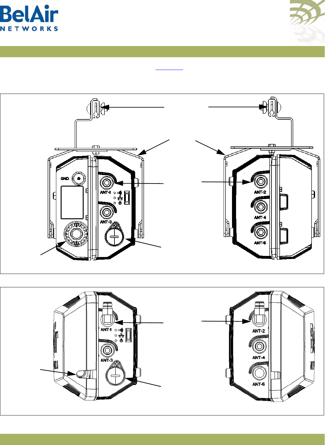
BelAirOS User Guide Configuring Wi-Fi Radio Parameters
April 22, 2012 Confidential Page 109 of 362
Document Number BDTM00000-A02 Draft
BelAir100SN. Refer to Figure 13 for the BelAir100N. The setting for the
port
parameter affects the maximum transmit power setting for your 5 Ghz radio.
Figure 12: BelAir100SN Connector Fields
Figure 13: BelAir100N Connector Fields
Ethernet
Connector
GRS
Connector
Antenna
Connectors
Strand Cable
Clamp
Strand Mount
Bracket
Right Side View Left Side View
Ethernet
Connector
Antenna
Connectors
Right Side View Left Side View
Protective
Cover Slot
for Power
Cable

BelAirOS User Guide Configuring Wi-Fi Radio Parameters
April 22, 2012 Confidential Page 110 of 362
Document Number BDTM00000-A02 Draft
See also:
•“Country of Operation” on page 66
•“Operating Channel” on page 105
• the
Radio Transmit Power Tables
Tra ns m it Power
Level
/interface/wifi-<n>-<m>/set tx-power
{<tx-power-value> [secondary <tx-power-value>]|
maximum-tx-power}
/interface/wifi-<n>-<m>/set tx-power
{{<tx-power-value> [secondary <tx-power-value>]
[tx-power-optimize
{{enable [target-rssi <rssi_level>]
[max-tx-power <max_power>]}|disable}]} |
maximum-tx-power }
This command sets the transmit power for a Wi-Fi radio. On all radios you can
specify specific power values with <tx-power-value> or select
maximum-tx-power
which tells the radio to operate at the maximum transmit
power allowed for your configuration.
The range of <tx-power-value> is limited to be valid for your country of
operation, physical channel in use, and type of antenna that is installed. Use the
show available-config-options
command to display valid transmit power values
(in dBm). The displayed values vary depending on the country of operation and
channel in use. If you enter a value for <tx-power-value> outside its valid range,
the AP issues a warning and instead uses an appropriate minimum or maximum
power setting for the radio.
The default setting is to have the radio transmit at maximum power.
The
secondary
parameter applies only to 5.8 GHz radios. It sets the transmit
power for an optional secondary channel for use with Dynamic Frequency
Selection (DFS), a regulatory requirement in some jurisdictions. The default is
to have the same transmit power level for both the primary and secondary
channel. Refer to your RF plan and site survey to determine if you need to set a
different power level for the DFS secondary channel.
For BelAir20EO APs equipped with a 2.4 GHz and a 5.8 GHz radio, you can
also use the
tx-power-optimize
parameter on the 5.8 GHz radio to enable
automatic transmit power control. This feature negotiates the minimal power
to maintain the maximum modulation rate.
If
tx-power-optimize
is enabled, <tx-power-value> is the default power level.
You must also specify the target RSSI level for the other end of the link and the
maximum power level that the link can transmit.

BelAirOS User Guide Configuring Wi-Fi Radio Parameters
April 22, 2012 Confidential Page 111 of 362
Document Number BDTM00000-A02 Draft
During operation, the RSSI level of the remote end of the link is monitored and
compared to the target RSSI level. If they are sufficiently different, the transmit
power level is adjusted. The <max_power> parameter limits the output of the
radio.
Automatic transmit power control operates only on the local end of the link.
To operate on both ends of a link, you must enable
tx-power-optimize
on both
ends of the link.
CAUTION! Improper setting of the transmit power may exceed regulatory requirements
and void the operator’s right to operate the radio equipment.
See also:
•“Country of Operation” on page 66
•“Operating Channel” on page 105
•“Antenna Gain” on page 108
Link Distance /interface/wifi-<n>-<m>/set link-distance <distance>
This command adjusts the AP’s MAC timers to compensate for the additional
time to receive acknowledgements because the other AP is farther. The
distance
parameter has a range of 0 to 40 and is specified in kilometers. The
default value is 1 km.
Dynamic
Frequency
Selection
/interface/wifi-<n>-<m>/show dfs
This command does not apply to platforms that do not have a 5.8 GHz radio,
such as the BelAir20E-10.
This command displays current Dynamic Frequency Selection (DFS) settings, a
regulatory requirement in some jurisdictions. DFS is automatically implemented
depending on the country of operation.
See also:
•“Country of Operation” on page 66
•“Operating Channel” on page 105
•“Transmit Power Level” on page 110
Example
/interface/wifi-1-1# show dfs
DFS admin state : enabled
current channel : 53
channel DFS radar holdoff-time

BelAirOS User Guide Configuring Wi-Fi Radio Parameters
April 22, 2012 Confidential Page 112 of 362
Document Number BDTM00000-A02 Draft
# required detected remaining
------------------ --------- ---------- ------------
primary: 53 no no 0 (sec)
secondary: 53 no no 0 (sec)
Collision Aware
Rate Adaptation
/interface/wifi-<n>-<m>/set advanced-collision-ctrl
{enable|disable}
Collision Aware Rate Adaptation (CARA) is an advanced algorithm that turns
RTS on and off when it detects a collision. This allows frames that failed due to
the collision to get through without compromising the transmission rate (that
is, the RTS is sent at 1mpbs and clears the channel of collisions for the high rate
data packet).
By default, CARA is enabled.
WCS Duty Cycle
Control
/interface/wifi-<n>-<m>/set duty-cycle-control {enable|disable}
This command applies to the WCSv1 only.
This command enables or disables the 38% transmit duty cycle control
mechanism required by FCC regulations.
By default, WCS duty cycle control is enabled.
Rate Aware
Fairness
/interface/wifi-<n>-<m>/set rate-aware-fairness {enable|disable}
Rate aware fairness is a transmission algorithm that chooses dynamic retreat
and progress thresholds based on the transmission rate of the station being
transmitted to, and the size of the packet.
Normally, when the AP has a client with a slower connection, all other clients
are throttled down to that same rate. Rate Aware Fairness overcomes this
issue by trying to give clients equal amounts of air-time instead of equal
numbers of packets.
By default, rate aware fairness is disabled.
Enhanced
Throughput
/interface/wifi-<n>-<m>/set enhanced-throughput {enable|disable}
This command applies to the WCSv1 only.
This command enables a performance enhancement method called
Fast Frames
which aggregates frames together before transmitting them as a single frame
carrying more data.

BelAirOS User Guide Configuring Wi-Fi Radio Parameters
April 22, 2012 Confidential Page 113 of 362
Document Number BDTM00000-A02 Draft
By default, enhanced throughput is enabled.
802.11n
Aggregation
/interface/wifi-<n>-<m>/set tx-aggr {enable|disable}
This command applies to the HTM and DRU only.
This command enables or disables transmit aggregation for the radio. Transmit
aggregation is an 802.11n feature where multiple MSDUs or MPDUs are packed
together to reduce the overhead and average them over multiple frames, thus
increasing the user level data rate.
The default setting is
enable
.
Minimum
Association
Thresholds
/interface/wifi-<n>-<m>/set rcv-rssi-filter
{disabled | enabled accept <value> discard <value>}
This command applies to the BelAir20, BelAir20E, BelAir20EO, BelAir100N,
BelAir100SN, BelAir100SNE and BelAir2100. It defines RSSI thresholds used
for client associations:
• A device can associate only if its Received Signal Strength Indicator (RSSI) is
equal or greater than the
accept
threshold.
• A device is forced to disassociate if its RSSI is continuously weaker than the
discard
threshold.
The
accept
value ranges from -40 to -100 dBm. The default value is -100 dBm.
The
discard
value ranges from -70 to -106 dBm. The default value is -106 dBm.
The
accept
threshold must be at least 6 dBm stronger than the
discard
threshold.
Doing an RF
Survey
/interface/wifi-<n>-<m>/show rf-survey [{ap [chan {others|all}]|
backhaul|
all}]
[mac {belair|others}]
[sort mac]
This command allows you to determine potential backhaul configuration
problems or rogue access points. It displays several information items for all
Wi-Fi radios it can currently detect.
The output is different, depending on whether you specify
ap
or
backhaul
. See
the following subsections for details:
•“AP RF Survey” on page 114

BelAirOS User Guide Configuring Wi-Fi Radio Parameters
April 22, 2012 Confidential Page 114 of 362
Document Number BDTM00000-A02 Draft
•“Backhaul RF Survey” on page 115
•“All RF Survey” on page 117
•“Sorting the Output” on page 117
•“Filtering the Output” on page 117
Specifying
all
displays both AP and backhaul RF surveys.
AP RF Survey Rogue access points (APs) may be installed on a corporate network by
employees using low-cost equipment they purchased themselves. The rogue
APs are often installed inside the corporate firewall with even the most basic
security settings disabled, thus creating the potential for network security
breaches. A rogue device may also be connected to a totally separate wired
network that happens to be near corporate facilities but is still accessible to
client devices within the enterprise.
For public networks, numerous Wi-Fi networks may exist “underneath” the
public network, being in or near the coverage area.
In some cases, a rogue AP may present a security concern. In all cases, rogue
APs are a source of interference and capacity degradation for the network.
Use the
show rf-survey ap
command to detect rogue access points (APs). In
this case, the
rf-survey
command displays the following information items for
every AP “visible” to a radio for the current channel in use:
• the AP’s MAC address
• the channel number it is using
• the Remote Signal Strength Indication (RSSI) of the link in dBm
• the age of the association (number of seconds since last signal was received
from the MAC address)
• the BSS configuration type, either
infra
(for infrastructure) or
adhoc
• whether privacy is enabled or not
• its SSID
Using a
show rf-survey
is equivalent to using
show rf-survey ap
.
When you use
show rf-survey ap
, you can filter the output as follows:
•
show rf-survey ap chan others
displays only the APs using channels other
than the one you are using.
•
show rf-survey ap chan all
displays all channels and all detected APs.

BelAirOS User Guide Configuring Wi-Fi Radio Parameters
April 22, 2012 Confidential Page 115 of 362
Document Number BDTM00000-A02 Draft
The
ap chan others
and
ap chan all
options display data collected with the
set
channel background-scan
command. Background scanning is not
service-affecting and clients should not be disconnected. To use these options,
the
background-scan
option must be enabled. See “Operating Channel” on
page 105.
Note: If you want to detect rogue APs that use a different channel than the
one used by your BelAir Networks radio, then you can choose to
change your radio’s channel and repeat this command to detect all
possible rogue APs. However, changing a radio’s channel is service
affecting and could disrupt client access. See “Operating Channel” on
page 105 for the command to changing a radio’s channel. BelAir
Networks recommends that you use instead the
show rf-survey ap
chan all
which provides equivalent information but is not service
affecting. See “Filtering the Output” on page 117 for details.
Example
/interface/wifi-1-1# show rf-survey ap
mac addr ch rssi age bss privacy ssid
----------------- --- ---- --- --- ------- ----------------
00:07:85:B3:73:94 149 -90 11 ifr no tsunami
00:0D:67:10:F0:BF 149 -68 8 ifr yes BelAir-Visitor
00:0D:67:10:F0:BD 149 -67 8 ifr yes BelAir-HotSpot
noise floor (chain 1-2): ............. -89 (dbm), -92 (dbm)
In the previous example, two of the devices visible to the BelAir Networks
radio have SSIDs that start with
BelAir
indicating the network being deployed
with BelAir Networks equipment. A third device has an SSID
tsunami
,
indicating a potential rogue AP. By examining the MAC address, you can
interpret that the rogue is a Cisco AP. The rogue is transmitting on channel 149
with no encryption and has a fairly low RSSI. This rogue is located within the
field of view of the AP that is performing the rogue query. The rogue likely
interferes most with the BelAir Networks APs.
Backhaul RF Survey Use the
show rf-survey backhaul
command to troubleshoot potential backhaul
configuration problems. In this case, the
rf-survey
command displays a list of all
visible backhaul links sharing the same channel that the radio is using. The
output can include APs that are configured with:
• different mesh or link identifiers
• different privacy settings
• different topologies

BelAirOS User Guide Configuring Wi-Fi Radio Parameters
April 22, 2012 Confidential Page 116 of 362
Document Number BDTM00000-A02 Draft
The output may show
undef
as the type of privacy, meaning that the AP cannot
determine the type of privacy used by that link.
Example 1 - Point-to-point Topology
/interface/wifi-4-1# show rf-survey backhaul
mac ch rssi age priv topo role linkIdx identifier state role identifier
(dbm) (s) [S] [S] 12345678 [S] [M] [M] [M]
----------------- -- ---- --- ---- ---- ---- -------- ---------------------- ----- ---- ------------
00:0D:67:08:63:31 157 -42 0 none p2p -- -------- BelAirNetworks dis
noise floor (chain 1-2): ............. -86 (dbm), -91 (dbm)
Example 2 - Multipoint-to-multipoint Topology
/interface/wifi-3-1# show rf-survey backhaul
mac ch rssi age priv topo role linkIdx identifier state role identifier
(dbm) (s) [S] [S] 12345678 [S] [M] [M] [M]
----------------- -- ---- --- ---- ---- ---- -------- ---------------------- ----- ---- ------------
00:0D:67:00:B3:55 167 -76 0 aes mesh -- -------- BelAirNetworks dis
00:0D:67:00:C9:A8 167 -58 0 aes mesh -- -------- BelAirNetworks dis
00:0D:67:00:E3:A3 167 -52 0 aes mesh -- -------- BelAirNetworks dis
noise floor (chain 1-2): ............. -86 (dbm), -91 (dbm)
Example 3 - Point-to-multipoint Topology, Base Station
This example shows a backhaul RF survey from an AP that is a stationary base
station connected to two stationary subscriber stations. The AP also sees
another AP but does not make a connection to it due to different topology
(p2p).
/interface/wifi-2-1# show rf-survey backhaul
mac ch rssi age priv topo role linkIdx identifier state role identifier
(dbm) (s) [S] [S] 12345678 [S] [M] [M] [M]
----------------- -- ---- --- ---- ---- ---- -------- ---------------------- ----- ---- ------------
00:0D:67:00:49:EA 167 -52 0 aes star ss 1------- BelAirNetworks dis
00:0D:67:00:B3:55 167 -90 0 aes p2p -- -------- BelAirNetworks dis
00:0D:67:00:C9:A8 167 -75 0 aes star ss --1----- BelAirNetworks dis
noise floor (chain 1-2): ............. -86 (dbm), -91 (dbm)
Example 4 - Point-to-multipoint Topology, Subscriber Station
This example shows a backhaul RF survey from one of the stationary subscriber
stations of Example 3.
/interface/wifi-2-1# show rf-survey backhaul
mac ch rssi age priv topo role linkIdx identifier state role identifier
(dbm) (s) [S] [S] 12345678 [S] [M] [M] [M]
----------------- -- ---- --- ---- ---- ---- -------- ---------------------- ----- ---- ------------
00:0D:67:00:B3:55 167 -73 0 aes star bs 111----- BelAirNetworks dis
00:0D:67:00:C9:A8 167 -58 0 aes p2p -- -------- BelAirNetworks dis
00:0D:67:00:E3:A3 167 -53 0 aes star bs --1----- BelAirNetworks dis
noise floor (chain 1-2): ............. -86 (dbm), -91 (dbm)

BelAirOS User Guide Configuring Wi-Fi Radio Parameters
April 22, 2012 Confidential Page 117 of 362
Document Number BDTM00000-A02 Draft
Example 5 - Mobile Backhaul Mesh Links
This example shows a backhaul RF survey for an AP providing mobile backhaul
mesh links.
/interface/wifi-2-1# show rf-survey backhaul
mac ch rssi age priv topo role linkIdx identifier state role identifier
(dbm) (s) [S] [S] 12345678 [S] [M] [M] [M]
----------------- -- ---- --- ---- ---- ---- -------- ---------------------- ----- ---- ------------
00:0D:67:00:C9:A8 167 -79 0 aes -- -- -------- BelAirNetworks ena ss mtest1
00:0D:67:00:49:EA 167 -66 0 aes mesh -- -------- BelAirNetworks ena bs mtest1
00:0D:67:00:E3:A3 167 -80 0 aes mesh -- -------- BelAirNetworks ena bs mtest1
noise floor (chain 1-2): ............. -86 (dbm), -91 (dbm)
All RF Survey Use the
show rf-survey all
command to display a list of all visible backhaul links
and all visible APs, except those sharing the same channel that the radio is
using.
Filtering the Output The
mac
option allows you to filter the output:
•
mac belair
displays only BelAir Networks APs; that is, only devices with
BelAir Networks MAC addresses
•
mac others
displays only APs that do not have BelAir Networks MAC
addresses.
Sorting the Output Use the
sort mac
option to sort the output in descending order by MAC
address.
Changing Wi-Fi
Interface Admin
State
/interface/wifi-<n>-<m>/set admin-state {enable|disable}
This command controls the state of the Wi-Fi interface including all links.
When set to
enable
, the Wi-Fi interface is in the operational state. When set to
disable
, the Wi-Fi interface and all associated functions are disabled. The default
is
disabled
.
Use the
/interface/wifi-<n>-<m>/show config
command to view the current
admin state of the Wi-Fi interface.
Wi-Fi Interface
Statistics
/interface/wifi-<n>-<m>/show statistics
This command displays the statistics for a Wi-Fi interface.
Example
/interface/wifi-1-1# show statistics
MSDU Statistics:
RX: .................. 0
TX: .................. 133805

BelAirOS User Guide Configuring Wi-Fi Radio Parameters
April 22, 2012 Confidential Page 118 of 362
Document Number BDTM00000-A02 Draft
RX Mcast: ............ 0
TX Mcast: ............ 133805
Access Rx Fail Rate (frames/min): 0
Access Rx Dup Rate (frames/min): 0
Access Rx OOR Rate (frames/min): 0
Access Tx Fail Rate (frames/min): 0
MPDU Statistics:
RX: .................. 17694466
TX: ................. 1104110
FCS Errors: .......... 0
WEP Undecryptable: ... 0
RTS Success: ......... 235053
RTS Failures: ........ 0
ACK Failures: ........ 0
Failed: .............. 0
Retries: ............. 0
Multiple Retries: .... 0
Frame Dups: .......... 0
Privacy Rejected Statistics:
Transmit: ............ 0
Plain: ............... 0
Encrypted: ........... 0
No Key: .............. 0
DoS Statistics:
deauth attacks: ...... 0
Backhaul Link Statistics:
Link Rx_Pkts Tx_Pkts Rx_Bytes Tx_Bytes Rx_Errs Tx_Errs
---- ------- ------- -------- -------- ------- -------
1 131828 405913 15326450 35360815 0 0
Wi-Fi
Performance
Monitoring
Statistics
/interface/wifi-<n>-<m>/show pm {fifteen-min|day}
[{<0-96>|<0-7>|all{msdu|mpdu|error-rate|
rx-modulation|tx-modulation|aggr|duty-cycle}}]
This command displays a radio’s performance measurements either for a
specific time interval or for a series of time intervals. The valid parameter
options are:
•
fifteen-min
,
fifteen-min 0
to
fifteen-min 96
,
fifteen all msdu
,
fifteen all mpdu
,
fifteen all error-rate
,
fifteen all rx-modulation
,
fifteen all tx-modulation
or
fifteen all aggr
•
day
,
day 0
to
day 7
,
day all msdu
,
day all mpdu
,
day all error-rate
,
day all
rx-modulation
,
day all tx-modulation
or
day all aggr
Note: Depending on the type and vintage of radio, not all statistics may be
available.
Specifying
fifteen-min
is equivalent to specifying
fifteen-min 0
and means the
current 15-minute interval. Specifying
day
is equivalent to specifying
day 0
and
means the current day, excluding data from the current 15-minute period.

BelAirOS User Guide Configuring Wi-Fi Radio Parameters
April 22, 2012 Confidential Page 119 of 362
Document Number BDTM00000-A02 Draft
When specifying a specific time interval
The output displays various statistics for that interval, including:
• MAC Service Data Unit (MSDU) statistics, including the delivery error rate
and the transmit on air error rate for transmitted packets
• MAC Protocol Data Unit (MPDU) statistics, including the delivery error rate
and the transmit on air error rate for data packets and management packets
• the number of packets received and transmitted at various modulation rates
• the number of packets transmitted in each of the QoS traffic priority queues
• a series of 802.11n aggregate statistics
MSDUs are received at the MAC layer and then either fragmented or
concatenated with other recently received MSDUs to form an MPDU.
When specifying
all
intervals
The output displays a radio’s performance measurements in table format for a
series of day or 15-minute time intervals. Each interval is displayed as a row.
Individual statistics are displayed as columns.
The data in the table varies, depending on your selection, as follows:
• Selecting
msdu
displays the MSDU statistics:
—
TxSOk
is the number of packets successfully transmitted.
—
TxMulticast
is the number of multicast packets transmitted.
—
TxDropped
is the number of dropped transmit packets.
—
TxFailed
is the number of failed transmit packets.
—
RxSOk
is the number of packets successfully received.
—
RxMulticast
is the number of multicast packets received.
—
RxDropped
is the number of dropped received packets.
—
RxFailed
is the number of failed received packets.
• Selecting
mpdu
displays the MPDU statistics:
—
TxOk
is the number of packets successfully transmitted.
—
TxFailed
is the number of failed transmit packets.
—
AckFailed
is the number of failed acknowledge packets.

BelAirOS User Guide Configuring Wi-Fi Radio Parameters
April 22, 2012 Confidential Page 120 of 362
Document Number BDTM00000-A02 Draft
—
MgtTxOk
is the number of management packets successfully transmitted.
—
MgtTxFailed
is the number of failed management transmit packets.
—
MgtAckFailed
is the number of failed management acknowledge packets.
• Selecting
error-rate
displays the error rates for MSDU and MPDU statistics:
—
Tx Error Rate (delivery)
is the percent of dropped and failed packets over
the total number of packets transmitted.
—
Tx Error Rate (on air)
is the percent of failed packets over the total
number of packets transmitted.
—
Data Tx Error Rate (delivery)
is the percent of dropped and failed
packets over the total number of transmitted data packets.
—
Data Tx Error Rate (on air)
is the percent of failed packets over the total
number of transmitted data packets.
—
Mgmt Tx Error Rate (delivery)
is the percent of dropped and failed
packets over the total number of transmitted management packets.
—
Mgmt Tx Error Rate (on air)
is the percent of failed packets over the total
number of transmitted management packets.
• Selecting
rx-modulation
displays the number of packets received at each
modulation rate.
• Selecting
tx-modulation
displays the number of packets transmitted at each
modulation rate.
• Selecting
aggr
displays the 802.11n aggregate statistics.
• Selecting
duty-cycle
displays:
—for the WCS radio, the number of times the transmitter was throttled to
prevent the duty-cycle target from being exceeded
—for all other radios. the percentage of time the radio is transmitting,
receiving or has a busy channel
Example 1
/interface/wifi-2-1# show pm fifteen-min
For non-WCS radios, the output is as follows:
Radio Performance - Interval type: current 15 minute Interval number: 0
MSDU stats:

BelAirOS User Guide Configuring Wi-Fi Radio Parameters
April 22, 2012 Confidential Page 121 of 362
Document Number BDTM00000-A02 Draft
TxOk: 15714 RxOk: 140462
TxMulticast: 0 RxMulticast: 0
TxDropped: 0 RxDropped: 0
TxFailed: 1525 RxFailed: 10190
Tx Error Rate: (delivery) 9 (on air) 9
MPDU stats:
TxOk: 15714 MgtTxOk: 1843 RxOk: 140462
TxFailed: 1525 MgtTxFailed: 1525 RxFramesErr: 10184
AckFailed: 3104 MgtAckFailed: 0 RxFrameAbort: 6
RxNotForUs: 3533 RxPhyAbort: 105593
TxRetries(1,2,3,4,>4): 54 1525 0 0 0
Data Tx Error Rate: (delivery) 9 (on air) 17
Mgmt Tx Error Rate: (delivery) 46 (on air) 0
No. Rx & Tx Frames at modulation rate (mbps aaa):
Rx 54.0: 89 Tx 54.0: 0
Rx 48.0: 60 Tx 48.0: 0
Rx 36.0: 15 Tx 36.0: 0
Rx 24.0: 3580 Tx 24.0: 0
Rx 18.0: 39 Tx 18.0: 0
Rx 12.0: 1753 Tx 12.0: 0
Rx 9.0: 241 Tx 9.0: 0
Rx 6.0: 8055 Tx 6.0: 0
Rx 11.0: 3279 Tx 11.0: 0
Rx 5.5: 24 Tx 5.5: 0
Rx 2.0: 9 Tx 2.0: 0
Rx 1.0: 123318 Tx 1.0: 17239
No. RX Frame Counts
Rate (Mbps) Rx-ok Duplicate w/ Retry w/o Retry Failed SNR Out of Range
No. Tx Frames on data queue (priority highest=3 ... lowest=0):
Queue 3: 0 Queue 1: 0
Queue 2: 1684 Queue 0: 0
Aggregation stats:
TxSingleMsdu: 0 TxAggrMsdu: 0 TxAggrAmpdu: 0
TxAggrMsduOk: 0 TxAggrAmpduOk: 0
TxAggrRetry: 0 TxAggrMaxRetry: 0 TxDropped: 0
RxMsdu: 0 RxMsduOk: 0
TxBars: 0 RxBars: 0 RxBarExchange 0
Tx Busy Indicator:
Average: 4 Max: 5 Min: 4
Rx Busy Indicator:
Average: 45 Max: 46 Min: 45
Channel Busy Indicator:
Average: 52 Max: 53 Min: 51
For WCSv1 radios, the final section of the output is as follows:
Tx Duty Cycle Control stats:
Average: 0 Max: 1 Min: 0 Limit Events: 0

BelAirOS User Guide Configuring Wi-Fi Radio Parameters
April 22, 2012 Confidential Page 122 of 362
Document Number BDTM00000-A02 Draft
Rx Busy Indicator:
Average: 0 Max: 0 Min: 0
Channel Busy Indicator:
Average: 0 Max: 1 Min: 0
Example 2 - Non-WCS radios
/interface/wifi-2-1# show pm fifteen-min all duty-cycle
int TxAverage TxMax TxMin RxAverage RxMax RxMin ChAverage ChMax ChMin
0 4 5 4 45 46 45 52 53 51
1 4 5 4 44 46 41 50 52 48
2 4 5 4 43 45 42 49 51 48
3 4 5 4 44 46 44 51 52 50
4 4 5 4 44 45 42 50 52 49
5 4 5 4 42 44 42 48 50 48
6 4 5 4 44 46 43 50 52 49
7 4 5 4 43 45 41 49 52 48
8 4 5 4 44 45 43 50 52 49
9 4 5 4 44 46 43 50 52 50
10 4 5 4 45 46 44 51 52 51
11 4 5 4 44 46 43 51 53 50
12 4 5 0 38 46 6 44 53 7
13 0 0 0 3 6 0 3 7 0
Example 3 - WCS radios
/interface/wifi-2-1# show pm fifteen-min all duty-cycle
int TxAverage TxMax TxMin Limit Events RxAverage RxMax RxMin ChAverage ChMax ChMin
0 0 1 0 0 0 0 0 0 1 0
1 0 0 0 0 0 0 0 0 0 0

BelAirOS User Guide Configuring Wi-Fi Access Point Parameters
April 22, 2012 Confidential Page 123 of 362
Document Number BDTM00000-A02 Draft
Configuring Wi-Fi Access Point Parameters
This chapter describes how to display and configure Wi-Fi Access Point (AP)
parameters, including:
•“Displaying AP Configuration” on page 124
•“AP Custom Rates” on page 124
•“Displaying Associated Wireless Clients” on page 126
•“Displaying Wireless Client Details” on page 128
•“Disconnecting a Wireless Client” on page 128
•“Wireless Client Load Balancing” on page 129
•“Configuring RTS-CTS Handshaking” on page 129
•“Specifying the Beacon Period” on page 129
•“Displaying Client Association Records” on page 130
•“Changing AP Admin State” on page 131
•“AP Service Set Identifiers” on page 131
—“Displaying the SSID Table” on page 132
—“Displaying SSID Details” on page 133
—“Default Management SSID” on page 133
—“Configuring SSIDs” on page 134
—“Upstream User Priority Marking” on page 136
—“Setting Traffic Limits” on page 136
—“Limiting the Number of Clients per SSID” on page 136
—“Providing Vendor Specific Information” on page 137
—“Changing SSID Admin State” on page 139
—“Wi-Fi SSID Performance Monitoring Statistics” on page 139
•“Out-of-service Advertising” on page 140
•“Filtering Broadcast and Multicast Packets” on page 141
•“Broadcast to Unicast Packet Conversion” on page 142

BelAirOS User Guide Configuring Wi-Fi Access Point Parameters
April 22, 2012 Confidential Page 124 of 362
Document Number BDTM00000-A02 Draft
•“ARP Filtering” on page 143
•“ARP to Unicast Conversion” on page 143
•“802.11b Protection” on page 144
•“Wi-Fi Client Statistics” on page 144
See also:
•“Configuring Wi-Fi Radio Parameters” on page 103
•“Wi-Fi AP Security” on page 146
•“Wi-Fi Backhaul Link Configuration” on page 161
•“Mobile Backhaul Mesh” on page 169
Displaying AP
Configuration
Use the
show config access
command to display the current AP configuration.
See “Displaying Wi-Fi Radio Configuration” on page 104 for details.
Example - BelAir20E
/interface/wifi-1-1# show config access
Slot: 1, Card Type: htme, revision: 1, Port: 1, Radio: HTMv1 5GHz
802.11n
admin state: ................. Enabled
channel: ..................... 149
mode: ...................... ht40plus
mimo: ...................... 3x3
tx power: .................. 18.0 (dBm per-chain), 23.0 (dBm total)
antenna location: ............ External Port
antenna index: ............... 1
antenna gain: ................ 5.0 (dBi)
link distance: ............... 1 (km)
base radio MAC : ............. 00:0d:67:0c:21:90
Access:
AP admin state: ............ Enabled
secure addresses (vlan): ... none
client blacklist: .......... none
dhcp unicast: .............. Disabled
deauth dos defense: ........ Disabled
client auth trap: .......... Disabled
Misc:
rts-cts threshold: ......... 100
broadcast filter status: ... Disabled
broadcast filter rate: ..... 200
AP Custom Rates /interface/wifi-<n>-<m>/show custom-rates
/interface/wifi-<n>-<m>/set custom-rates {disabled |
enabled [{add|del} [b <rate_string>]
[g <rate_string>]
[ht <rate_string>]}

BelAirOS User Guide Configuring Wi-Fi Access Point Parameters
April 22, 2012 Confidential Page 125 of 362
Document Number BDTM00000-A02 Draft
These commands let you customize the modulation rates used by your 802.11n
radio by building a list of rates to include. Putting a rate on the list allows the
radio to use that rate.
The
show
command displays modulation rates that are currently on the list;
that is, the rates that the radio uses. Rates that have short preamble are
indicated with
sp
.
Use the
set
command to enable or disable the custom rates feature. By default,
the custom rates feature is disabled.
Once you enabled custom rates, use the
add
and
del
parameters to create the
specific list of rates that you need. The
<rate_string>
parameter is one of rates
output by the
show custom-rates
command.
If you use the
set
command without specifying a custom rate, a list of valid
custom rates is displayed.
Note: Adding a rate does not mean that the radio automatically begins to use
that rate. The modulation rate selected by a radio depends on several
factors. The custom rates list is just one of those factors.
Example 1 - Using Custom Rates
/interface/wifi-1-2# set custom-rates enabled
Valid custom b rates are:
11,5.5,2,1,11(sp),5.5(sp),2(sp)
Valid custom g rates are:
48,24,12,6,54,36,18,9
Valid custom n rates are:
mcs0,mcs1,mcs2,mcs3,mcs4,mcs5,mcs6,mcs7
/interface/wifi-1-2# show custom-rates
Custom-rate is enabled and the list includes:
A/G : 48 24 12 6 54 36 18 9
B : 11 5.5 2 1 11(sp) 5.5(sp) 2(sp)
HTSS : mcs0 mcs1 mcs2 mcs3 mcs4 mcs5 mcs6 mcs7
HTDS : mcs8 mcs9 mcs10 mcs11 mcs12 mcs13 mcs14 mcs15
Example 2 - Using Custom Rates
/interface/wifi-1-2# show custom-rates
Custom-rate is enabled and the list includes:
A/G : 48 24 12 6 54 36 18 9
/interface/wifi-1-2# set custom-rates enabled del g 18
/interface/wifi-1-2# show custom-rates
Custom-rate is enabled and the list includes:
A/G : 48 24 12 6 54 36 9

BelAirOS User Guide Configuring Wi-Fi Access Point Parameters
April 22, 2012 Confidential Page 126 of 362
Document Number BDTM00000-A02 Draft
Displaying
Associated
Wireless Clients
/interface/wifi-<n>-<m>/show clients [ssid <ssid_index>]
This command displays the list of associated wireless clients for a given SSID. If
no SSID is specified, the displayed list shows all associated clients and their
SSID.
The
ssid_index
parameter must be a valid SSID index.
In the resulting output:
• The
time
field displays how long the client has been associated to the BelAir
Networks radio.
• The
IP
field lists the client's IP address. (s) indicates static IP addressing.
• The
identity
field lists the 802.1X client identity. It is present for dot1x or
WPA SSIDs.
• The
auth
field lists the authentication state of the client. See Tab l e 9 .
• The
dhcp
field lists the client DHCP state (applicable only if client uses
dynamic IP addressing). See Table 10 on page 126.
Table 9: Auth Field Value Descriptions
Value Description
unauth default or initial state
auth client is authorized for Open or WEP privacy
eapAuth client is authorized for dot1x, WPA1 or WPA2 privacy
pskErr Possible wrong WPAPSK key configured on client
radto For dot1x, WPA1 or WPA2. Problems connecting to radius
server, possibly because of a network problem.
cltto For dot1x, WPA1 or WPA2. Problems sending EAP packets to
client.
Table 10: DHCP Field Value Descriptions
Value Description
init Client has just connected and has not yet started a DHCP
sequence

BelAirOS User Guide Configuring Wi-Fi Access Point Parameters
April 22, 2012 Confidential Page 127 of 362
Document Number BDTM00000-A02 Draft
Depending on the server configuration, if a client moves to a different subnet, it
may need to timeout the current IP address (approx. 30 seconds) and then
restart the DHCP sequence. During this process the client may use the
standard default IP address for Microsoft Windows (169.254.X.X).
disc Client has sent a DHCP Discover message and is waiting for a
DHCP Offer message to get its IP address.
(Applicable only if client does not already have a valid IP address.
Otherwise client sends DHCP Request message.)
offer Server has responded to the DHCP Discover message with a
DHCP Offer message. This packet tells the client its IP address.
The client should then send a DHCP Request message to verify the
IP address.
req Client has sent the DHCP Request message to the server and is
waiting for a DHCP Ack message to confirm the assigned IP
address.
decl Server has declined the client’s DHCP request. Verify the server
settings.
ack Client has sent a DHCP Request message and the server has
confirmed the assigned IP address.
(a * appended to the value indicates a completed DHCP process.)
nack Server has responded to the client’s DHCP request with a DHCP
Nack message. Verify the server settings.
relse Client has sent a DHCP Release message.
inform Client has sent a DHCP Inform message. Depending on the server,
the server may respond with a DHCP Ack message.
(a * appended to the value indicates a completed DHCP process.)
arpRes Client has gone through one of the DHCP state transitions and
replied to an ARP request for its IP address.
(a * appended to the value indicates a completed DHCP process.)
Table 10: DHCP Field Value Descriptions (Continued)
Value Description

BelAirOS User Guide Configuring Wi-Fi Access Point Parameters
April 22, 2012 Confidential Page 128 of 362
Document Number BDTM00000-A02 Draft
Example
/interface/wifi-2-1# show clients
SS-ID vlan mac addr time IP identity rssi auth dhcp
----- ---- ----------------- ---- ------------------ ---------- ---- ------- ------
2-4 0 00:11:24:26:24:AA 4m 10.9.9.20(s) -82 eapAuth static
Displaying
Wireless Client
Details
/interface/wifi-<n>-<m>/show client <1|2|...|2007>
[throughput] [stats]
This command displays the details of a wireless client that is associated or was
recently associated with the AP. You determine the client number
<1|2|...|2007>
with the
show clients
command. See “Displaying Associated
Wireless Clients” on page 126.
The
throughput
parameter displays additional information on traffic throughput.
The
stats
parameter allows displays additional information on packet statistics.
In the resulting output, the
age
parameter shows the time since the radio last
received a data frame from the client and the
state
parameter shows
authenticated (2)
if the client is no longer associated.
Example
/interface/wifi-1-1# show client 35
Ssid: ........... 1
Vlan: ........... 0
Mac Address: .... 00:18:DE:98:28:E8
Connected Time: . 0 yrs 0 days 00:00:42
Aging Time: ..... 0 seconds
Ip Address: ..... 10.1.1.60
Identity: .......
Rssi: ........... -48 (dBm)
Auth State: ..... Authenticated(open/wep)
Dhcp State: ..... Client sent ARP response (complete)
Disconnecting a
Wireless Client
/interface/wifi-<n>-<m>/disconnect client <mac_address>
This command lets you disconnect the specified client from the AP.
You determine the client MAC address with the
show clients
command. See
“Displaying Associated Wireless Clients” on page 126.

BelAirOS User Guide Configuring Wi-Fi Access Point Parameters
April 22, 2012 Confidential Page 129 of 362
Document Number BDTM00000-A02 Draft
Wireless Client
Load Balancing
/interface/wifi-<n>-<m>/set max-num-clients <max_num> [strict]
This command lets you set the maximum number of clients that can associate
with the AP. Once the maximum is reached, new client associations are not
immediately accepted.
While using this command, keep in mind the following:
• If you do not use the
strict
parameter, and a new client continues to try to
associate after the client maximum is reached, the AP does accept it after
three retries. (All association retries in a one minute interval is considered a
single retry.)
• If you use the
strict
parameter, the AP does not accept a new client when
the client maximum is reached, even if the new client to tries to associate
repeatedly.
• Changing the client maximum does not take effect until two minutes later.
• Changing the client maximum does not disconnect any existing client.
The <max_num> parameter ranges from 0 to 256. The default is 256.
Configuring
RTS-CTS
Handshaking
/interface/wifi-<n>-<m>/set rts-cts {disabled|enabled <threshold>}
This command lets you enable or disable Request-to-Send (RTS) and
Clear-to-Send (CTS) handshaking.
When enabled, handshaking occurs for packets larger than the threshold. The
<threshold> parameter can range from 1 to 65536. The default value is 100.
By default, dynamic rate handshaking is
disabled
.
Specifying the
Beacon Period
/interface/wifi-<n>-<m>/set beacon-period
{auto | <bp_value> [dtim <dt_value>]}
This command lets you specify the behavior of your beacon period for
broadcast Service Set Identifiers (SSIDs). See also “AP Service Set Identifiers”
on page 131.
If specified, the
<bp_value>
parameter specifies a fixed beacon period in
milliseconds. It ranges from 100 to 400.
The optional
<dt_value>
parameter specifies the DTIM value. It ranges from 1
to 3.

BelAirOS User Guide Configuring Wi-Fi Access Point Parameters
April 22, 2012 Confidential Page 130 of 362
Document Number BDTM00000-A02 Draft
If you select
auto
, the AP automatically adjusts the beacon period and DTIM
value dynamically according to the number of MBSSIDs.
The default setting is to have a fixed beacon period of 100 ms with a DTIM
value of 3.
Displaying Client
Association
Records
/interface/show client-record <num_entries> [radio <radioIf_name>]
[vlan {<vlan_id>| none}] [mac-addr <mac_address>]
[aggregation | start <start_idx>]
/interface/show client-record detail <num_entries>
Every 15 minutes, the AP generates wireless client association records. A client
record includes the following information:
• The IP address, MAC address, VLAN, RSSI, DHCP state, and authentication
state of the client.
• The radio interface and SSID index for the radio the Wi-Fi client is
associated to.
• The start and end connection time, as well as the times a client has a
throughput greater than 2 kBps or transmits more than 2 kB of traffic.
If a client connection crosses more than one 15-minute interval, another client
record is generated for that client. A
continue
flag indicates that the client has
another record in the next 15-minute interval.
The
num_entries
parameter specifies the number of entries to display.
You can filter the output based on the following optional parameters:
•Use
radio <radioIf_name>
to filter for records of clients connected to a
particular Wi-FI interface, such as
wifi-2-1
.
•Use
vlan <vlan_id>
to filter for records of clients using a particular VLAN,
or no VLAN.
•Use
mac-addr <mac_address>
to filter for records with a client’s MAC
address.
•Use
aggregation
to show combined client records when a client connection
crosses multiple 15-min boundary. Use
start <start_idx>
to show client
records starting from a particular record index number. The starting index
number is always unique.
Use the
show client-record detail
command to display details of a particular
client record.
BelAirOS User Guide Configuring Wi-Fi Access Point Parameters
April 22, 2012 Confidential Page 131 of 362
Document Number BDTM00000-A02 Draft
Example - Non Aggregated Records
/interface# show client-record 4
SSID Start Time Connect IP MAC RSSI Vlan RX TX Continue
ID Radio INX dd hh:mm:ss mm:ss address address max avg min Id KB KB flag
11 wifi-2-1 1 11 06:42:57 15:02 10:1:1:7 00:18:de:c2:30:46 -25 -44 -64 0 90 109 Yes
10 wifi-2-1 1 11 06:27:55 15:02 10:1:1:7 00:18:de:c2:30:46 -25 -44 -64 0 60 72 Yes
9 wifi-2-1 1 11 06:12:53 15:02 10:1:1:7 00:18:de:c2:30:46 -25 -44 -64 0 268 323 Yes
8 wifi-2-1 1 11 05:57:51 15:02 10:1:1:7 00:18:de:c2:30:46 -25 -44 -64 0 219 250 Yes
Example - Aggregated Records
/interface# show client-record 20 aggregation
SSID Start Time End Time IP MAC RSSI Vlan RX TX Cross Byte Cross Rate
ID Radio INX dd hh:mm:ss dd hh:mm:ss address address avg Id KB KB dd hh:mm:ss dd hh:mm:ss
1 wifi-2-1 1 11 04:57:41 11 04:59:40 10:1:1:7 00:18:de:c2:30:46 -42 0 5 4 11 04:58:42 not exceed
3 wifi-2-1 1 11 05:00:11 11 05:01:25 10:1:1:7 00:18:de:c2:30:46 -45 0 11 8 11 05:00:52 not exceed
4 wifi-2-1 1 11 05:08:02 11 06:57:59 10:1:1:7 00:18:de:c2:30:46 -44 0 1074 1255 11 05:08:21 not exceed
Example - Client Record Detail
Figure 14: Client Record Detail Example
Changing AP
Admin State
/interface/wifi-<n>-<m>/set ap admin-state {enable|disable}
This command controls the state of the AP. When set to
enable
, the AP is in
the operational state. When set to
disable
, the AP and all associated functions
are disabled. The default is
enabled
.
AP Service Set
Identifiers
Use the commands in this section to:
• configure AP Service Set Identifiers (SSIDs)
• map an SSID to a VLAN
/interface# show client-record detail 4
Client Record INX[4]:
Radio Interface: wifi-2-1
SSID Idx: 1
Start Time (mon-dd hh:mm:ss): 07-11 05:08:02
End Time (mon-dd hh:mm:ss): 07-11 05:12:45
Vlan ID: 0
IP Address: 10:1:1:7
MAC Address: 00:18:de:c2:30:46
RSSI(dbm): max -25, min -64, avg -43
Exceed Throughput(2KB) Time: 07-11 05:08:21
Throughput: Rx 35KB, Tx 33KB
Authenticate State: Authenticated(open/wep)
DHCP State: Client sent ARP response
Is Continued: Yes
When the client logged in
When the record ends
Client RSSI information
Time when client crossed the 2 kbyte
threshold.
Same as
show client detail
command.
If
Yes
, record continues into next
15-minute window.

BelAirOS User Guide Configuring Wi-Fi Access Point Parameters
April 22, 2012 Confidential Page 132 of 362
Document Number BDTM00000-A02 Draft
• provide vendor specific information
Each AP supports up to 8 SSIDs. If associated clients use different SSIDs, then
the AP can use the SSID to direct traffic to different VLANs.
Displaying the SSID
Table
/interface/wifi-<n>-<m>/show ssid table
This command summarizes in table format the parameters of all configured
SSIDs. In the resulting output:
• The
broadcast
setting is the default for SSID 1. A
broadcast
setting means
that the access radio responds to a broadcast probe request and that SSID
information element is present in the beacon dataframe. A
broadcast
SSID
has a Basic Service Set (BSS), a unique identifier having the same format as a
MAC address.
•A
suppressed
setting means that the access radio responds only to a unicast
probe request and that SSID information element is present in the beacon
dataframe, but has a length of 0 and a null value. A
suppressed
SSID has a
Basic Service Set (BSS), a unique identifier having the same format as a MAC
address.
Example - Typical Output
/interface/wifi-1-1# show ssid table
SSID Information
-------------------------------------------------------------------------------------
id enabled vlan type privacy wb sp acl bss ssid
-------------------------------------------------------------------------------------
1 yes -- Broadcast none -- -- -- 00:0D:67:0C:21:98 RickBA20E-15-2
2 no -- Suppressed none -- -- -- 00:0D:67:0C:21:99 DefaultSsid2-2
3 no -- Suppressed none -- -- -- 00:0D:67:0C:21:9A DefaultSsid2-3
4 no -- Suppressed none -- -- -- 00:0D:67:0C:21:9B DefaultSsid2-4
5 no -- Suppressed none -- -- -- 00:0D:67:0C:21:9C DefaultSsid2-5
6 no -- Suppressed none -- -- -- 00:0D:67:0C:21:9D DefaultSsid2-6
7 no -- Suppressed none -- -- -- 00:0D:67:0C:21:9E DefaultSsid2-7
8 no -- Suppressed none -- -- -- 00:0D:67:0C:21:9F DefaultSsid2-8
====================================================================================
In the previous example:
•
wb
is for wireless bridge; see “Disabling or Enabling AP Wireless Bridging”
on page 157
•
sp
is for secure port; see “AP Secure Port Mode” on page 159
•
acl
is for access control list; see “Wireless Client Access Control List” on
page 155

BelAirOS User Guide Configuring Wi-Fi Access Point Parameters
April 22, 2012 Confidential Page 133 of 362
Document Number BDTM00000-A02 Draft
•
bss
is for basic service set; see “Configuring SSIDs” on page 134
• a star ( * ) means that the feature is enabled for that particular SSID
• a double dash ( -- ) means that the feature is not enabled for that particular
SSID
Displaying SSID Details /interface/wifi-<n>-<m>/show ssid <ssid_index> config
This command displays details of a particular SSID. Use the
show ssid table
command to determine
<ssid_index>
.
Example
/interface/wifi-1-1# show ssid 3 config
Configuration for ssid 3
admin state: ..................... Enabled
SSID: ............................ DefaultSsid2-1
AP oos identifier: ............... outOfService..
mbssid state: .................... Enabled
type: ............................ Broadcast
privacy mode: .................... none
rekey: ........................... Disabled
key strict: ...................... no
traffic mapped to vlan: .......... none
passthrough vlan(s): ............. disabled
wireless bridge state: ........... Disabled
group address filter: ............ none
upstream UP marking: ............. Disabled (0)
acl state: ....................... Disabled
secure port state: ............... Disabled
arp unicast conversion state: .... Disabled
radius NAS identifier: ........... belair
radius accounting: ............... Disabled
radius station id unformatting: .. Disabled
radius account session id: ....... Disabled
secure addresses (vlan):
No secure addresses configured
client blacklist:
No blacklist entries
auto secure gateway: ............. enabled
Address Vlan
00:0a:5e:49:1c:33 (500)
00:0a:5e:49:1c:8b (600)
radius servers:
No radius servers configured for this ssid
DHCP relay servers:
Server[1] Addr: 10.1.100.88
sub-option: 150/151 inserted
sub-option151: vpn-selector
Option82 Insert Enabled.
Default Management
SSID By default, SSID 8 of each radio is a suppressed SSID preconfigured for a
management session.

BelAirOS User Guide Configuring Wi-Fi Access Point Parameters
April 22, 2012 Confidential Page 134 of 362
Document Number BDTM00000-A02 Draft
The default management SSID is
BelAir-<MAC_info>
, where <MAC_info> is
the last six digits of the AP’s MAC address.
For example, if an AP has a MAC address of
00:0D:67:08:48:98
, the default
management SSID is
BelAir-084896
.
By default, SSID 8:
• uses WPA encryption with the following pre-shared key:
DefaultKey123
.
Users may wish to change the security settings to suit their needs.
• is not mapped to a VLAN. Users may wish to map SSID 8 to a separate
VLAN reserved for management sessions.
Refer to the following topics for details on changing the default settings for
SSID 8:
• To change the SSID and map it to a VLAN, see “Configuring SSIDs” on
page 134.
• To change the security settings, see “Wi-Fi AP Security” on page 146.
Configuring SSIDs /interface/wifi-<n>-<m>/set ssid <ssid_index>
service-set-identifier <ssid_string>
{broadcast | suppressed}
vlan {<vlanID-list>|none}
[passthrough-vlan {<passvlanID-list>|none}]
This command allows you to configure AP SSIDs.
The
ssid_string
parameter is the SSID setting. SSIDs are case sensitive and can
contain up to 32 alphanumeric characters. To specify a blank string, input two
double quotes (““).
The
ssid_index
parameter is an integer from 1 to 8. Use the
show ssid table
command to determine
<ssid_index>
.
For a description of the
broadcast
and
suppressed
parameters, see “Displaying
the SSID Table” on page 132.
The
vlanID-list
parameter, if present, specifies a comma separated list of VLAN
IDs. Each VLAN ID must be an integer from 1 to 3015 and from 3018 to 4045.
The list can contain up to eight VLAN IDs.
The
vlanID-list
parameter activates functionality to balance traffic among up to
eight VLANs, based on the last three bits of the MAC address of the wireless
client generating the traffic. The last three bits of the MAC address can range in
value from 0 to 7. For example:

BelAirOS User Guide Configuring Wi-Fi Access Point Parameters
April 22, 2012 Confidential Page 135 of 362
Document Number BDTM00000-A02 Draft
• Traffic from clients where the last three bits have a value of 0 is directed to
the first VLAN on the list.
• Traffic from clients where the last three bits have a value of 1 is directed to
the second VLAN on the list.
• Traffic from clients where the last three bits have a value of 6 is directed to
the seventh VLAN on the list.
If the last three bits of the MAC address does not reference a VLAN on the list,
then the client's traffic is directed to the first VLAN on the list.
If the
vlan
parameter is
none
and the wireless client is sending untagged traffic,
then the traffic corresponding to the specified SSID is passed through the
access radio without change. If the wireless client is sending tagged traffic, then
you can use the
passvlanID-list
parameter.
The
passvlanID-list
parameter, if present, also specifies a comma separated list
of VLAN IDs. As with the
vlanID-list
parameter, each VLAN ID must be an
integer from 1 to 3015 and from 3018 to 4045, and the list can contain up to
eight VLAN IDs.
The
passvlanID-list
parameter applies to pre-tagged traffic; for example,
generated from Linux wireless clients. If the traffic’s VLAN tag matches a VLAN
on the list, then that traffic is allowed to go through unchanged. Otherwise, the
tagged traffic from the client is dropped.
If
passvlanID-list
is populated, then
vlanID-list
can specify only one VLAN ID. In
such cases, untagged traffic from the client is tagged with the VLAN from
vlanID-list
. If the VLAN ID list is set to
none
, then untagged traffic from the
client remains untagged.
If the passthrough VLAN list is
none
, tagged packets from a wireless client are
dropped. Untagged packets from the client are tagged with the VLAN ID from
vlanID-list
according to the last three bits of the client’s MAC address.
CAUTION! This caution applies to the BelAir100N, BelAir100SN, BelAir100SNE and
BelAir2100. If your network contains a BelAir200, you must configure its VLAN
subsystem with the specified VLAN ID before using this command on a
BelAir100SN. Refer to the
BelAir200 User Guide
for instructions on
configuring VLAN subsystems. All traffic from the specified client is discarded by
the BelAir200 if the mapped VLAN is not previously configured.

BelAirOS User Guide Configuring Wi-Fi Access Point Parameters
April 22, 2012 Confidential Page 136 of 362
Document Number BDTM00000-A02 Draft
Upstream User Priority
Marking
/interface/wifi-<n>-<m>/set ssid <ssid_index>
upstream-up-marking {enabled|disabled}
[ up-value <val> ]
This command enables or disables the ability to set the User Priority (UP) value
of any packet received by the AP for a particular SSID. The UP values are then
used throughout the network to separate and prioritize traffic through Quality
of Service (QoS) settings. See “Quality of Service Settings” on page 225 for
details.
By default, upstream UP marking is
disabled
.
The
ssid_index
parameter must be a valid SSID index. See “AP Service Set
Identifiers” on page 131
Setting Traffic Limits /interface/wifi-<n>-<m>/set ssid <ssid_index> traffic-limit
([upstream <bits-per-second>]
[downstream <bits-per-second>])
This command allows you to control the amount of traffic the AP sends for a
particular SSID:
•Use the
upstream
parameter to specify the amount sent to the network.
•Use the
downstream
parameter to specify the amount sent to wireless
clients.
• Specify 0 to remove previously set limits.
Use the
show ssid table
command to determine
<ssid_index>
. Use the
show
ssid <ssid_index> config
command to see the currently configured values.
Limiting the Number of
Clients per SSID
/interface/wifi-<n>-<m>/set ssid <ssid_index>
client-limit-priority <priority-number>
[min <minimum-guaranteed>]
[max <maximum-allowed>]
This command allows you to control the number of clients that a particular
SSID can service. The sum of all clients for all SSIDs cannot exceed the limit set
with the
set max-num-clients <max_num>
command. (See “Wireless Client
Load Balancing” on page 129.)
The associated parameters are:
•Use
<priority-number>
to assign a priority number to the SSID. Priority
numbers range from 1 to 8, where 8 is the highest priority. The default
priority is 1.

BelAirOS User Guide Configuring Wi-Fi Access Point Parameters
April 22, 2012 Confidential Page 137 of 362
Document Number BDTM00000-A02 Draft
•Use the
min
parameter to specify the minimum number of clients this SSID
is guaranteed to serve. The default setting is 0.
•Use the
max
parameter to specify the maximum number of clients this SSID
can have. The default setting is 256.
Use the
show ssid table
command to determine
<ssid_index>
. Use the
show
ssid <ssid_index> config
command to see the currently configured values.
Providing Vendor
Specific Information
/interface/wifi-<n>-<m>/set ssid <ssid-number>
option82 insertion {enabled|disabled}
/interface/wifi-<n>-<m>/set ssid <ssid-number> option82 use
([circuit-id {enabled | disabled}]
[remote-id {enabled | disabled}]
[vendor-option {enabled | disabled}]
[scope-selector {enabled | disabled}])
/interface/wifi-<n>-<m>/set ssid <ssid-number>
option82-circuit-id
{SSID | custom-field <num_str>}
/interface/wifi-<n>-<m>/set ssid <ssid-number>
option82-remote-id
{node-mac | custom-field <num_str>}
/interface/wifi-<n>-<m>/set ssid <ssid-number>
option82-scope-selector <random_str>
For any SSID, you can add vendor specific option 82 information to DHCP
packets. Typically, this is done when DHCP relay functionality is enabled with
the
set ssid <ssid_index> dhcp-relay
command. (For details see “Assigning
SSID Traffic to Use DHCP Relay” on page 193.) However, vendor specific
information can be added even if DHCP relay is disabled. In such cases, a
warning is displayed but the vendor specific information is still added to the
packets.
Use the
set ssid option82 insertion
command to control whether DHCP
option 82 (DHCP relay agent information) is inserted into packets or not.
Relay agent information can be packaged in the following option 82 suboption
fields:
• Circuit ID; that is, suboption 1
• Remote ID; that is, suboption 2
• Vendor option; that is, suboption 9
• Scope selector; that is, suboptions 150 and 151
If option 82 insertion is enabled, use the
set ssid option82 use
command to
control which fields (circuit ID, remote ID, vendor option, or scope selector)
are used. You can use any or all of these fields.

BelAirOS User Guide Configuring Wi-Fi Access Point Parameters
April 22, 2012 Confidential Page 138 of 362
Document Number BDTM00000-A02 Draft
Note: There are DHCP packet length limitations. If you enable all fields, then
the DHCP packet may not be large enough to contain all the vendor
specific information. In such cases, some vendor specific information
may not be inserted into the packet properly and the packet may be
marked as
Malformed Packet
. However, the packet still contains the IP
address.
If you enable circuit ID (suboption 1), by default the field contains the SSID. You
can also use the
set ssid option82-circuit-id
command to configure the field to
use one of the five custom fields described in “Custom Fields” on page 67.
If you enable remote ID (suboption 2), by default the field contains the AP MAC
address. You can also use the
set ssid option82-remote-id
command to
configure the field to use one of the five custom fields described in “Custom
Fields” on page 67.
If you enable vendor option (suboption 9), the relay agent information is
packaged as follows:
• agent circuit ID
• Subsuboption 1, the MAC address of your AP
• Subsuboption 2, VLAN identifier
• Subsuboption 3, Radio MAC address
• Subsuboption 4, SSID: the SSID that is using the DHCP relay functionality
• Subsuboption 5, GPS coordinates
If you enable scope selector (suboption 150 and 151), the relay agent
information is packaged as follows:
• Suboption 150. The VLAN info is packaged as follows:
0x96, 0x04,0xn, 0xn, 0xn, 0xn
Where:
—The first field is always 0x96, identifying Suboption 150.
—The second field is always, 0x04, specifying the length of the VLAN info.
—The last four fields are 0xn, where each value of n is a digit specifying the
VLAN number.
For example, 0x96, 0x04, 0x1, 0x2, 0x0, 0x0 specifies VLAN 1200. VLAN
100 would be specified as 0x96, 0x04, 0x0, 0x1, 0x0, 0x0.

BelAirOS User Guide Configuring Wi-Fi Access Point Parameters
April 22, 2012 Confidential Page 139 of 362
Document Number BDTM00000-A02 Draft
• Suboption 151. The VPN selection ID is packaged as follows:
0x97, 0x0a, 0x00, 0xnn, 0xnn, 0xnn, 0xnn, 0xnn, 0xnn, 0xnn, 0xnn, 0xnn
Where:
—The first field is always 0x97, identifying Suboption 151.
—The second field specifies the length of the VPN selection ID.
—The remaining fields specify an ASCII string of the VPN selection ID.
If Suboption 150 and 151 are selected, use the
set ssid option82-scope-selector
command to specify the VPN selection ID. You can specify an ASCII string of up
to 32 alphanumeric characters. To specify a blank string, input two double
quotes (““).
If Suboption 150 and 151 are selected and a Suboption 151 string is undefined,
the SSID string is used instead.
Changing SSID Admin
State
/interface/wifi-<n>-<m>/set ssid <ssid_index> admin-state
{enable|disable}
This command enables or disables a particular SSID. Use the
show ssid table
command to determine
<ssid_index>
.
The default is
enabled
for SSID 1 and
disabled
for all others.
Wi-Fi SSID Performance
Monitoring Statistics
/interface/wifi-<n>-<m>/show ssid <ssid_index> pm
{fifteen-min|day} [{<num_str>|all}]
This command displays an SSID’s performance measurements either for a
specific time interval or for a series of time intervals. This command applies to
all non-WCS radios.
The
ssid_index
parameter must be a valid SSID index. For details see
“Configuring SSIDs” on page 134.
The valid time parameter options are:
•
fifteen-min
,
fifteen-min 0
to
fifteen-min 96
, and
fifteen-min all
•
day
,
day 0
to
day 7
, and
day all
Note: Depending on the type and vintage of radio, not all statistics may be
available.

BelAirOS User Guide Configuring Wi-Fi Access Point Parameters
April 22, 2012 Confidential Page 140 of 362
Document Number BDTM00000-A02 Draft
Specifying
fifteen-min
is equivalent to specifying
fifteen-min 0
and means the
current 15-minute interval. Specifying
day
is equivalent to specifying
day 0
and
means the current day, excluding data from the current 15-minute period.
When specifying a specific time interval
The output displays the following statistics for the specified SSID:
•
TxByte
and
RxBytes
are the number of bytes sent and received.
•
NumberOfMacs
is the number of unique client MAC addresses that have
associated with the AP
•
NumberOfAssociations
is the number of successful client associations
•
NumberOfAuthorized
is the number of associated clients that have received
at least 25,000 bytes of traffic from the AP.
When specifying
all
intervals
The output displays an SSID’s performance measurements in table format for a
series of day or 15-minute time intervals. Each interval is displayed as a row.
Individual statistics are displayed as columns.
Example 1
/interface/wifi-2-1# show ssid 1 pm fifteen-min
SSID 1 Performance - Interval type: current 15 minute Interval number: 0
TxByte: 1589 RxBytes: 0
NumberOfMacss: 0 NumberOfAssociation:0 NumberOfAuthorized:0
Example 2
/interface/wifi-2-1# show ssid 1 pm fifteen-min all
int TxBytes RxBytes NumberOfMacs NumberOfAssociation NumberOfAuthorized
0 342 2188 0 1 0
1 10182662 63106 1 1 1
Out-of-service
Advertising
/interface/wifi-<n>-<m>/set ssid <ssid-number> ap-oos-identifier
<oos_string>
/system/set ap-oos-broadcast-delay <oos_delay>
/interface/wifi-<n>-<m>/set ap-oos-broadcast {enabled|disabled}
[option {replace|prepend}]
/system/show ap-oos-broadcast-delay
These commands let you modify the SSIDs of a radio with an out-of-service
string when an AP loses its egress connection for longer than the period
specified by
<oos_delay>
. The out-of-service string can be prepended to the
existing SSID or it can replace the existing SSID. The out-of-service string can

BelAirOS User Guide Configuring Wi-Fi Access Point Parameters
April 22, 2012 Confidential Page 141 of 362
Document Number BDTM00000-A02 Draft
contain up to 14 characters. The default string is
outOfService..
and by default
it replaces the SSID.
The out-of-service delay (<oos_delay>) ranges from 30 to 300 seconds. The
default is 300 seconds. The out-of-service delay is set for the entire AP. Use the
/system/show ap-oos-broadcast-delay
command to display the current delay.
When an AP’s egress connection is declared out-of-service, the AP also applies
WPA AES encryption with a 16-character pre-shared key to all SSIDs except
for the default management SSID. This is to prevent a user from accidently
connecting to an open SSID which is in out-of-service. The 16-character
pre-shared key consists of the first 10 characters of the out-of-service identifier
followed by the last six digits of the AP’s MAC address. If the out-of-service
identifier is less than 10 characters, then period characters (.) are used to
complete the first 10 characters of the pre-shared key.
The status of an AP's egress connection is determined as follows:
1 If a tunnel is enabled, the egress status is the tunnel's status.
2 If a tunnel is not enabled and there is a cable modem in the system, the
egress status is the modem's status.
3 If a tunnel is not enabled and there is no cable modem in the system, the
egress status is the Ethernet link's status.
See also:
•“Default Management SSID” on page 133
•“Security Options for Wireless Clients” on page 146
Filtering
Broadcast and
Multicast Packets
/interface/wifi-<n>-<m>/set ssid <ssid_index>
group-address-filter {none | ipv4}
This command filters all broadcast and multicast packets to and from a wireless
client except for ARP and DHCP packets, allowing you to reduce the amount of
broadcast and multicast traffic in the network.
The
ssid_index
parameter must be a valid SSID index. See “AP Service Set
Identifiers” on page 131
Use the
none
setting to disable this function. Use
ipv4
to enable this function.
If wireless bridging is enabled, the default is
none
. If wireless bridging is disabled,
the default is
ipv4
.

BelAirOS User Guide Configuring Wi-Fi Access Point Parameters
April 22, 2012 Confidential Page 142 of 362
Document Number BDTM00000-A02 Draft
See also:
•“Limiting Broadcast Packets” on page 73
•“Broadcast to Unicast Packet Conversion” on page 142
Broadcast to
Unicast Packet
Conversion
/interface/wifi-<n>-<m>/set ssid <ssid_index>
dhcp-advanced {upstream-unicast | none}
This command lets you convert broadcast packets to unicast packets. Reducing
the number of broadcast packets sent over wireless connections provides the
following benefits:
• Broadcast packet are not retried in wireless transmissions, so in high
interference environments wireless clients can miss their DHCP exchange.
• It reduces the bandwidth required for exchanges of DHCP messages.
The
ssid_index
parameter be a valid SSID index. See “AP Service Set
Identifiers” on page 131.
The
set ssid <ssid_index> dhcp-advanced
command is set to
none
by default,
meaning that it is disabled. In this case:
• All BOOTP packets, including DHCP packets, coming from the client are
examined to determine if they are broadcast or unicast. This information is
stored for use when the response arrives.
• All BOOTP packets, including DHCP packets, arriving from the network are
examined. If needed, they are converted to match the format (broadcast or
unicast) sent by the wireless client.
When the
set ssid <ssid_index> dhcp-advanced
command is set to
upstream-unicast
, it unsets the Request Broadcast bit for BOOTP packets,
including DHCP packets, originating from clients before sending those packets
to the network. This means that the network should respond with unicast
packets instead of broadcast packets.
The
set ssid <ssid_index> dhcp-advanced
command does not affect BOOTP
packets arriving from the network. All BOOTP packets, including DHCP
packets, arriving from the network are examined. If needed, they are converted
to match the format (broadcast or unicast) sent by the wireless client.
See also:
•“Limiting Broadcast Packets” on page 73
•“Filtering Broadcast and Multicast Packets” on page 141

BelAirOS User Guide Configuring Wi-Fi Access Point Parameters
April 22, 2012 Confidential Page 143 of 362
Document Number BDTM00000-A02 Draft
ARP Filtering /interface/wifi-<n>-<m>/set arp-filtering {disabled|enabled}
This command enables or disables ARP filtering on radio traffic from the AP to
the wireless client. When enabled, the radio only forwards ARP request
packets to a currently connected client. Otherwise, the downstream ARP
requests are dropped.
The default setting is
disabled
.
ARP to Unicast
Conversion
/interface/wifi-<n>-<m>/show arp-unicast-table [vlan <vlan_id> ]
/interface/wifi-<n>-<m>/set ssid <ssid_index>
arp-unicast-conversion {enabled|disabled}
These commands control the conversion of upstream ARP packets to unicast
packets.
When enabled, this feature intercepts ARP requests from wireless clients and
sends them only to known gateway MAC addresses. ARP responses from the
gateway are sent to the wireless client without interception and manipulation.
When the AP starts, the ARP unicast conversion table is empty. So the first
ARP packet from the client is sent out as is; no conversion happens. When the
ARP response arrives, the AP records its information, including the unicast
MAC address, in the conversion table. For the following ARP packets, the AP
replaces the broadcast MAC address in the ARP packet with the unicast MAC
address from the conversion table.
When a conversion table entry is used, a 4-second response timer is started. If
the ARP response arrives within 4 seconds, then the entry remains valid.
Otherwise the entry is deemed invalid and removed from the table. Each entry
is removed after 4 hours of inactivity.
The table holds up to 128 entries.
The default setting is
disabled
.
Example
/interface/wifi-1-2# show arp-unicast-table
vlaid ip mac expire
----------------------------------------------------------------
5 10.1.5.53 00:10:18:27:bc:07 03:57:18
0 10.1.1.53 00:10:18:27:bc:07 03:59:32
90 10.1.90.53 00:10:18:27:bc:07 03:59:55

BelAirOS User Guide Configuring Wi-Fi Access Point Parameters
April 22, 2012 Confidential Page 144 of 362
Document Number BDTM00000-A02 Draft
802.11b
Protection
/interface/wifi-<n>-<m>/set b-protection {disabled|enabled}
This command enables or disables 802.11b protection for the radio. Normally,
an 802.11g AP uses CTS-to-self to interact with 802.11b APs. The transmitted
packet is small, but in High Capacity and Interference environments the
accumulated effect is a substantial performance penalty. This feature disables
802.11b protection for the radio, meaning that CTS-to-self are not sent and
maximizing the throughput for wireless clients that operate in the 2.4 GHz
range.
This feature improves performance if there are only a few 802.11b clients
present and they are not generating large amounts of traffic. If not, the 802.11b
clients may generate substantial numbers of collisions and actually impair traffic.
The default setting is
enabled
.
Wi-Fi Client
Statistics
/interface/wifi-<n>-<m>/show client <ssidIdx-clientIdx>
[throughput] [stats]
/interface/wifi-<n>-<m>/clear client {all|<ssidIdx-clientIdx>}
These commands display radio transmission statistics for a particular client.
Use the
show clients
command to determine the
<ssidIdx-clientIdx>
parameter. See the “Displaying Associated Wireless Clients” on page 126 for
details on the
show clients
command.
In the output of the
show client <ssidIdx-clientIdx> [throughput] [stats]
command:
• The
Attempts
column contains the number of packets for which the initial
transmission attempt was made at the specified rate.
• The
Success
column contains the number of packets for which transmission
succeeded at the specified rate.
• The
Start Rate Change
column contains the number of times the specified
rate was changed to be the initial transmission rate.
• The
Tx Retries
entry describes the number of times 0, 1 or more retries
were required.
• The
Tx Failures
entry indicates the number of packets which were placed on
the air at least once but never acknowledged.
• The
Tx Dropped
entry indicates the number of packets dropped without
ever being transmitted (due to interference).

BelAirOS User Guide Configuring Wi-Fi Access Point Parameters
April 22, 2012 Confidential Page 145 of 362
Document Number BDTM00000-A02 Draft
Example
/interface/wifi-2-1# show client 2-4 throughput stats
Ssid: ........... 2
Vlan: ........... 0
Mac Address: .... 00:11:24:26:24:AA
Connected Time: . 0 yrs 0 days 00:04:46
Aging Time: ..... 1 seconds
Ip Address: ..... 10.9.9.20 (static)
Identity: .......
Rssi: ........... -82 (dBm)
Auth State: ..... Authenticated(dot1x/wpa)
Dhcp State: ..... Static (in-progress)
Tx: Bytes 1360 Bytes/Sec 136 Avg Bytes/Sec 142 Moving Avg Bytes/Sec 571
Tx: Pkts 10 Pkts/Sec 1 Avg Pkts/Sec 1 Moving Avg Pkts/Sec 5
Rx: Bytes 980 Bytes/Sec 98 Avg Bytes/Sec 111 Moving Avg Bytes/Sec 446
Rx: Pkts 10 Pkts/Sec 1 Avg Pkts/Sec 1 Moving Avg Pkts/Sec 6
Tx Rate Attempts Success Start Rate Change
54 146 6 55
48 193 157 58
36 4 174 3
24 2 8 1
18 1 1 1
12 1 1 0
6 0 0 0
2 0 0 0
1 0 0 0
Tx Retries(0,1,2,3,4,>4): 87 198 62 0 0 0
Tx Failures: 0
Tx Dropped: 0
Tx Efficiency: 51
Rx Rate Success Duplicate
54 0 0
48 0 0
36 441 5
24 10 0
18 2 0
12 0 0
6 0 0
2 0 0
1 4 0

BelAirOS User Guide Wi-Fi AP Security
April 22, 2012 Confidential Page 146 of 362
Document Number BDTM00000-A02 Draft
Wi-Fi AP Security
This chapter describes how you can set up security to encrypt your Wi-Fi
transmissions so that your data cannot be deciphered if it is intercepted, and to
prevent access to the network by unauthorized clients. The following topics are
covered:
•“Security Options for Wireless Clients” on page 146
•“RADIUS Servers for Wireless Clients” on page 148
—“Managing RADIUS Servers” on page 150
—“Changing RADIUS Server Admin State” on page 151
—“Assigning SSIDs to RADIUS Servers” on page 151
—“RADIUS Pre-authentication” on page 151
—“RADIUS Assigned VLAN” on page 152
—“RADIUS Accounting” on page 153
•“Client Authentication and De-authentication Trap” on page 153
•“AP Privacy” on page 153
•“Wireless Client Blacklist” on page 155
•“Wireless Client Access Control List” on page 155
•“Controlling Inter-client Communication” on page 156
•“Protecting against Denial of Service Attacks” on page 159
See also:
•“Configuring Wi-Fi Radio Parameters” on page 103
•“Configuring Wi-Fi Access Point Parameters” on page 123
•“Wi-Fi Backhaul Link Configuration” on page 161
•“Mobile Backhaul Mesh” on page 169
Security Options
for Wireless
Clients
The AP has several options for wireless authentication and data encryption.
The method that you use depends on your security needs and your network
configuration.

BelAirOS User Guide Wi-Fi AP Security
April 22, 2012 Confidential Page 147 of 362
Document Number BDTM00000-A02 Draft
If multiple SSIDs are configured, each SSID can be configured with its own
security options.
The authentication options are:
• instruct the AP to connect to a Remote Authentication Dial In User Service
(RADIUS) server in your network that keeps a list of accepted clients.
RADIUS is a standard for user authentication. For this option, you need a
RADIUS server. Multiple APs can share the information from the same
RADIUS server.
• use a pre-shared key. This is a simpler authentication option, but more
difficult to maintain because pre-shared keys must be distributed to all users.
You can also create a list of accepted clients; that is, an Access Control List
(ACL). This option is best suited for small networks.
The encryption options are:
• Wired Equivalent Privacy (WEP). This is a basic encryption scheme.
• Temporal Key Integrity Protocol (TKIP). This is an more advanced
encryption scheme.
• Advance Encryption Standard (AES). This is the strongest encryption
scheme.
BelAir Networks Wi-Fi radios offer WEP, WPA, WPA2 and WPA2mixed
privacy settings. With WPA2mixed, the wireless client can use WPA or WPA2,
and the AP accepts them both. WPA, WPA2 and WPA2mixed privacy uses
TKIP or AES encryption. Because of this, WPA, WPA2 and WPA2mixed
provide much stronger security than WEP. For small networks, you can use
WEP or WPA with pre-shared keys. For large networks, you can use WPA,
WPA2 or WPA2mixed in combination with dot1x (a RADIUS server)
authentication.
CAUTION! RADIUS authentication, WPA or WPA2 can only be used with wireless clients
that support these standards (both the operating system and the network card).
For clients that only support WEP, select a combination with WEP.
Note: A network is as secure as its weakest link. If WEP is enabled, the overall
level of network security will be that of WEP.

BelAirOS User Guide Wi-Fi AP Security
April 22, 2012 Confidential Page 148 of 362
Document Number BDTM00000-A02 Draft
RADIUS Servers
for Wireless
Clients
To use RADIUS authentication, you need to configure at least one RADIUS
server.
Table 11 shows the attributes that are included in the
access-request
messages
sent to the RADIUS server when using RADIUS (EAP) authentication.
Table 11: RADIUS Attributes
Name ID Description
RA_USERNAME 1 Client identity
RA_NAS_IP_ADDRESS 4 AP IP address configured with the
/protocol/radius/set
server
command. See “Managing RADIUS Servers” on
page 150.
RA_NAS_PORT 5 For accounting packets, contains the client association ID
that ranges from 1 to 256.
For RADIUS packets, contains the SSID index values (from
0 to 15) + 100
RA_SERVICE_TYPE 6 Always
2
RA_FRAMED_MTU 12 Always
1400
RA_STATE 24 Client state from the RADIUS server
RA_CLASS 25 Always
0
RA_VENDOR_SPECIFIC 26 Not used
RA_SESSION_TIMEOUT 27 RADIUS reauth time configured with the
/protocol/radius/
set server
command. See “Managing RADIUS Servers” on
page 150.
RA_IDLE_TIMEOUT 28 Client timeout value, always 5 minutes
RA_TERMINATION_ACTION 29 Incoming only (
0
for terminate or
1
for reauth)
RA_CALLED_STATION_ID 30 AP MAC address
If station-id-unformatting is set to enable, colons are
removed.

BelAirOS User Guide Wi-Fi AP Security
April 22, 2012 Confidential Page 149 of 362
Document Number BDTM00000-A02 Draft
RA_CALLING_STATION_ID 31 Client MAC address
If station-id-unformatting is set to enable, colons are
removed.
RA_NAS_IDENTIFIER 32 Name configured with the
/interface/wifi-<n>-<m>/set
ssid <ssid_index> radius
command. See “RADIUS
Accounting” on page 153.
RA_ACCT_STATUS_TYPE 40 Always
1
,
2
or
3
RA_ACCT_INPUT_OCTET 42 Integer counter
RA_ACCT_OUTPUT_OCTET 43 Integer counter
RA_ACCT_SESSION_ID 44 Unique number generated by system.
RA_ACCT_AUTH 45
1
for RADIUS or
2
for local
RA_ACCT_SESSION_TIME 46 RADIUS reauth time configured with the
/protocol/radius/
set server
command. See “Managing RADIUS Servers” on
page 150.
RA_ACCT_INPUT_PACKET 47 Integer counter
RA_ACCT_OUTPUT_PACKET 48 Integer counter
RA_TERMINATE_CAUSE 49 One of:
•
1
for session terminated by user request
•
2
for session terminated due to lost carrier
•
4
for session terminated due to idle timeout
•
5
for session timeout
•
9
for session terminated due to NAS error
•
20
for session terminated due to reauth failure
RA_ACCT_INPUT_GIGAWORDS 52 Not used
RA_ACCT_OUTPUT_GIGAWORDS 53 Not used
RA_EVENT_TIMESTAMP 55 System time when the RADIUS packet is sent
RA_NAS_PORT_TYPE 61 Always
19
for port type of wireless
Table 11: RADIUS Attributes (Continued)
Name ID Description

BelAirOS User Guide Wi-Fi AP Security
April 22, 2012 Confidential Page 150 of 362
Document Number BDTM00000-A02 Draft
Managing RADIUS
Servers
/protocol/radius/show servers
/protocol/radius/set server <server_idx> <server_ip_address>
<shared secret> [authport <server_port>]
[acctport <radius_acc_port>]
[interface <NAS IP address>] [timeout <seconds>]
[reauthtime <seconds>]
/protocol/radius/del server <server_idx>
These commands let you manage the RADIUS server list used for
authenticating wireless clients. The list can contain up to 16 RADIUS servers.
After the list is configured, you can then assign which AP SSID uses which
server on the list. See “Assigning SSIDs to RADIUS Servers” on page 151. By
default, if a RADIUS server is unavailable, then the SSID uses the next RADIUS
server in the list. You cannot delete a server if it is being used by an SSID.
The
server_ip address
parameter specifies the IP address of the RADIUS
server.
The
shared secret
parameter specifies the password for access to the RADIUS
server.
The
server_port
parameter ranges from 0 to 65535. It specifies the UDP port
number of the RADIUS server. The default is 1812.
The
radius_acc_port
parameter ranges from 0 to 65535. It specifies the UDP
port number for RADIUS accounting data. The default value is 1813.
The
NAS IP address
parameter specifies the Network Access Server (NAS) IP
address for the AP RADIUS client. It is used when the AP is configured with
multiple IP interfaces and matches the interface used to communicate with the
RA_TUNNEL_TYPE 64 Refer to “RADIUS Assigned VLAN” on page 152.
RA_TUNNEL_MEDIUM_TYPE 65 Refer to “RADIUS Assigned VLAN” on page 152.
RA_TUNNEL_PRIVATE_GROUP_ID 81 Refer to “RADIUS Assigned VLAN” on page 152.
RA_CONNECT_INFO 77 Always
CONNECT 11Mbps 802.11b
RA_EAP_MESSAGE 79 EAP packet
RA_MESSAGE_AUTHENTICATOR 80 Authentication string from RADIUS server
RA_INTERIM_INTERVAL 85 Not used
Table 11: RADIUS Attributes (Continued)
Name ID Description

BelAirOS User Guide Wi-Fi AP Security
April 22, 2012 Confidential Page 151 of 362
Document Number BDTM00000-A02 Draft
given RADIUS server. The default value is the IP address of the AP’s
management interface, which is usually the system’s default IP address.
Note: The
NAS IP address
parameter is entered statically with this command.
If the VLAN IP addresses are determined dynamically with a DHCP
server, then an updated VLAN IP address is not automatically reflected
into the
NAS IP address
parameter.
The
timeout
parameter ranges from 2 to 300. It specifies the interval (in
seconds) after which the RADIUS client considers that the remote server has
timed out if a reply is not received. The default value is 10 seconds.
The
reauthtime
parameter ranges from 0 to 50000000. It specifies the RADIUS
re-authentication time (in seconds). This forces the AP to check all connected
clients with the RADIUS server (that is, make sure they are still allowed to
access the network) at the specified interval. You only need to configure this
parameter if it is not specified on the RADIUS server. Setting the interval to
zero disables this feature. The maximum interval time is 2147483647. If you
enter a higher number, the value is set to its maximum.
Example
/protocol/radius# set server 3 172.16.1.20 my-secret12345 authport 1812 acctport 1813
interface 172.16.1.254 timeout 15 reauthtime 1
Changing RADIUS
Server Admin State
/protocol/radius/set server-state <server_idx> {enable|disable}
This command enables or disables a particular RADIUS server on the server
list. Use the
show servers
command to determine
<server_idx>
.
Assigning SSIDs to
RADIUS Servers
/interface/wifi-<n>-<m>/add ssid <ssid_index>
radius-server <server_idx>
/interface/wifi-<n>-<m>/del ssid <ssid_index>
radius-server <server_idx>
The
add
command specifies which RADIUS server to use to authenticate the
specified SSID. The
del
command means that the specified RADIUS server
stops authenticating the specified SSID. Use the
/wifi-<n>-<m>/show ssid table
command to determine
<ssid_index>
. Use the
/radius/show servers
command
to determine
<server_idx>
.
RADIUS
Pre-authentication
/interface/wifi-<n>-<m>/set ssid <ssid_index>
radius-pre-auth {enabled|disabled}
[delimiter {none|colon|dash}]
This feature allows you to set up a centralized access control list at the
RADIUS server instead of each AP. With this feature enabled, when an AP
receives a client’s association request, it composes an
access-request
message

BelAirOS User Guide Wi-Fi AP Security
April 22, 2012 Confidential Page 152 of 362
Document Number BDTM00000-A02 Draft
and sends it to a RADIUS server. If an
access-accept
message is received from
the RADIUS server, the AP continues with the client’s association procedure
and grants access based on other criteria such as encryption type and key
matching.
To use this feature, you must configure your RADIUS server to have a list of all
allowed clients. Each entry in this list includes a user name and a password. The
user name and the password must be set to the client’s MAC address. The
delimiter
parameter specifies whether the RADIUS packets use a colon (:), a
dash (-) or nothing as a delimiter when specifying a MAC address.
To reduce the message exchanges between the AP and RADIUS server, an AP
maintains two cache tables: one for all allowed clients and another for all
disallowed clients. When the AP receives a client’s association request, it first
searches both tables. If the client’s information is in the allowed table, the AP
bypasses RADIUS pre- authentication. If the client is in the disallowed table, it is
rejected immediately. Cache entries in either table expire in two minutes.
The feature can be enabled or disabled on each SSID. Use the
/wifi-<n>-<m>/
show ssid table
command to determine
<ssid_index>
.
The default setting is
disabled
.
RADIUS Assigned
VLAN The AP can create VLANs as instructed by the RADIUS server. When this
feature is activated, the RADIUS server instructs the AP to tag the
authenticated packets to use the specified VLAN.
This feature has no CLI commands. To activate this feature, you must provision
the following attributes on your RADIUS server:
• RA_TUNNEL_TYPE, set to
13
• RA_TUNNEL_MEDIUM_TYPE, set to
6
• RA_TUNNEL_PRIVATE_GROUP_ID, configure to contain the VLAN to be
created.
Refer to Table 11 on page 148.
CAUTION! This caution applies to the BelAir100N, BelAir100SN, BelAir100SNE and
BelAir2100. If your network contains a BelAir200, you must configure its VLAN
subsystems with the VLAN ID specified by the RADIUS server before it is
created on the BelAir100SN. Refer to the
BelAir200 User Guide
for
instructions on configuring VLAN subsystems. All traffic from the specified
client is discarded by the BelAir200 if the RADIUS assigned VLAN is not
previously configured.

BelAirOS User Guide Wi-Fi AP Security
April 22, 2012 Confidential Page 153 of 362
Document Number BDTM00000-A02 Draft
RADIUS Accounting /interface/wifi-<n>-<m>/set ssid <ssid_index> radius
([accounting {enable|disable}]
[nas-id <name>]
[delimiter {none|colon|dash}]
[append {none|ssid}]
These commands let you manage RADIUS accounting for wireless clients.
By default RADIUS accounting is disabled.
The
nas-id <name>
parameters specify the RADIUS Network Access Server
(NAS) identifier. The default value for
<name>
is
belair
.
The
delimiter
parameter specifies whether the RADIUS packets use a colon (:),
a dash (-) or nothing as a delimiter when specifying a MAC address.
The
append
parameter specifies RADIUS station ID formatting. The default
setting is
ssid
, meaning that the
called-station-ID
and the
calling-station-ID
fields
are formatted to include SSID information to the provided MAC address.
Client
Authentication
and
De-authentication
Trap
/interface/wifi-<n>-<m>/set client-trap {enabled|disabled}
[trap-delay {enabled|disabled}]
This command controls whether a trap is sent for this particular radio
whenever a wireless client authenticates or de-authenticates; that is,
disconnects from the radio. The trap can be used by any Network Management
System to monitor client activities.
When the client trap is enabled and the trap delay is enabled, the trap is not
sent out until 10 seconds after either of the following events:
• the client connects and stays connected
• the client is disconnected and stays disconnected
If the trap delay is disabled, then the trap is sent out immediately after either of
the previous events.
When the client trap is disabled, the trap is not sent out.
The default is to have both the client trap and trap delay enabled.
AP Privacy /interface/wifi-<n>-<m>/set ssid <ssid_index> privacy
{none|dot1x-open|wep40|wep104|
{wpa {tkip|aes}}|wpa2 {tkip|aes}|wpa2mixed}
[{psk <key-str>}|dot1x]

BelAirOS User Guide Wi-Fi AP Security
April 22, 2012 Confidential Page 154 of 362
Document Number BDTM00000-A02 Draft
[rekey {no|kpackets <count>|seconds <seconds>}]
[strict {yes|no}]
This command configures wireless privacy for a particular SSID. Use the
show
ssid table
command to determine
<ssid_index>
. Use the
show ssid
<ssid_index> config
command to show the current privacy settings.
The
dot1x-open
parameter specifies an open privacy setting, but uses a
RADIUS server for SSID authentication. The RADIUS server authenticates a
wireless client by its username and password. After accepting the client, the
RADIUS server does not provide encryption keys. The data transmission is
open
.
WPA, WPA2 and WPA2mixed privacy uses TKIP or AES encryption. With
WPA2mixed, the wireless client can use WPA or WPA2, and the AP accepts
them both.
The
psk
parameter specifies using a pre-shared key for authentication. When
specifying the pre-shared key, note the following:
•For
wep40
, the pre-shared key must be exactly 5 bytes.
•For
wep104
with
psk
, the pre-shared key must be exactly 13 bytes.
•For
wpa
,
wpa2
and
wpa2mixed
, the pre-shared key must be between 8 and
63 bytes long. The longer the key, the more secure the connection.
• The pre-shared key can be specified as a hexadecimal number or ASCII
string. Hexadecimal numbers must be preceded by
0X
or
0x
. ASCII strings
must not contain the following characters:
—bar (|)
—semicolon (;)
—question mark (?)
—double quotation mark (“)
The
dot1x
parameter specifies using RADIUS (EAP) authentication. You must
pre-configure a list of RADIUS servers. See “RADIUS Servers for Wireless
Clients” on page 148.
The
rekey
parameter allows you to specify Group Key Rekey options to
improve security. These options allow you to specify that a new group key (the
key that is used for communication between the access radio and a group of
clients) must be generated at regular intervals.

BelAirOS User Guide Wi-Fi AP Security
April 22, 2012 Confidential Page 155 of 362
Document Number BDTM00000-A02 Draft
The default
rekey
setting is
no
meaning that the group key is not changed. If
rekey
is set to
n
seconds, the group key is changed after that time period. If
rekey
is set to
n
kpackets, the group key is changed after that many thousand
packets.
If
strict
is set to
yes
, the group key changes immediately when one client leaves
the network. The default is
no
. The
strict
setting applies to wpa and wpa2
encryption only.
Additional Considerations
Make sure to set the AP SSID to something other than the default before
enabling
wpa
,
wpa2
or
wpa2mixed
. The AP combines the password phrase with
your SSID to create the key.
Note: Some configuration commands take longer than others to be applied to
a radio module. For example, it can take up to 40 seconds per SSID for
a WPA PSK configuration to be applied to radio. The delay varies
depending on the amount of computing resources required to
implement the configuration.
Wireless Client
Blacklist
/interface/wifi-<n>-<m>/add client blacklist <mac-addr>
/interface/wifi-<n>-<m>/del client blacklist <mac-addr>
These commands let you add and remove a MAC address from a client blacklist.
If a wireless client’s MAC address matches an entry on the blacklist, the client
cannot associate with the AP. The client blacklist can contain up to 16 entries.
Each physical interface can have its own client blacklist.
Use the
show config access
command to display the current client blacklist
entries.
Wireless Client
Access Control
List
/interface/wifi-<n>-<m>/show ssid <ssid_index> acl
[page <page-number> <page-size>]
/interface/wifi-<n>-<m>/add ssid <ssid_index> acl-mac-address
<mac-address>
/interface/wifi-<n>-<m>/del ssid <ssid_index> acl-mac-address
<mac-address>
/interface/wifi-<n>-<m>/set ssid <ssid_index> acl
{enabled|disabled}
You can create a local list of clients (an ACL) that controls access to the
network. The list can contain up to 16 clients per SSID. Clients are identified by
the MAC address of their network card. If you have multiple APAP in your
network, you need to create this list for every AP.

BelAirOS User Guide Wi-Fi AP Security
April 22, 2012 Confidential Page 156 of 362
Document Number BDTM00000-A02 Draft
You should only use an ACL as an extra security measure if:
• you cannot or prefer not to set up a RADIUS server
• your network provides access to network clients which do not support
RADIUS authentication
In both cases, it is recommended that you enable pre-shared key encryption
(WEP, WPA, WPA2 or WPA2mixed).
The
enabled
setting for the
set acl
command means that only the wireless
clients on the ACL can access the network. All other clients are denied access.
The
disabled
setting means that all wireless clients can access the network. See
also “AP Secure Port Mode” on page 159.
Typically, you enable ACL mode only after you have added all the desired MAC
addresses to the control list.
CAUTION! When used with multiple SSIDs, this method affects wireless clients attempting
to associate with any of the SSIDs.
Use the
show ssid table
command to determine
<ssid_index>
.
Controlling
Inter-client
Communication
If wireless bridging is enabled for an SSID, then by default wireless clients
associated to an AP and using that SSID can communicate to one another
(assuming they are able to determine the IP addresses of their peer wireless
clients).
For security reasons in a public network environment, it may be desirable to
block inter-client communications.
CAUTION! Provisioning inter-client communication can affect the wireless clients
associated with all the SSIDs of that AP.
The goal is to prevent communications between associated wireless clients and
still allow them to connect to the Internet. To do this, use one of the following
methods.
Manual Provisioning of Gateway MAC Addresses
The following method offers the precise control of SSID communications:
1 Determine the MAC address of the Internet gateway(s) or router(s) in your
network.
2 Disable wireless bridging for each AP in your network.

BelAirOS User Guide Wi-Fi AP Security
April 22, 2012 Confidential Page 157 of 362
Document Number BDTM00000-A02 Draft
3 Disable inter-AP wireless client communications:
a Add the previously determined gateway MAC address or addresses to the
secure MAC white list. This allows wireless clients to communicate with
the Internet. The secure MAC white list typically contains the MAC
address of the gateway interfaces.
b If the DHCP server for your network is on a different machine than the
gateway, add the MAC address of the DHCP server machine to the
secure MAC white list.
c Enable
secure port
mode for each of the APs in your network.
Automatic Discovery of Gateway MAC Addresses
The following method automates MAC address provisioning:
1 Disable wireless bridging for each AP in your network.
2 Disable inter-AP wireless client communications:
a Enable the
auto-secure gateway
feature for each of the APs in your
network.
b Enable
secure port
mode for each of the APs in your network.
Determining the MAC
Address of the Internet
gateway
This step is only required if you want to manually provision the MAC addresses
of the Internet gateway(s) or router(s) in your network.
Determining the MAC address of your Internet gateway(s) depends on the type
of equipment you are using. Refer to your equipment’s User Manual for the
specific details.
You will need the MAC address of your gateways later to provision the secure
MAC white list of the APs configured in
secure port
mode.
Disabling or Enabling AP
Wireless Bridging
/interface/wifi-<n>-<m>/set ssid <ssid_index> wireless-bridge
{enabled|disabled}
Use the
show ssid table
command to determine
<ssid_index>
.
Disabling wireless bridging for an AP prevents wireless clients associated to that
particular AP from communicating with one another.
It does not prevent a wireless client associated with one AP (AP “A”) from
communicating with a wireless client associated with another AP (AP “B”). The
secure port
mode prevents this. See “AP Secure Port Mode” on page 159.
By default, wireless bridging is
enabled
.

BelAirOS User Guide Wi-Fi AP Security
April 22, 2012 Confidential Page 158 of 362
Document Number BDTM00000-A02 Draft
Disabling Inter-AP
Wireless Client
Communication
Disabling inter-AP wireless client communications involves setting up a secure
MAC white list and enabling secure port mode for each AP.
Secure MAC White List /interface/wifi-<n>-<m>/add secure-mac-address <mac-address-string>
[secure-mac-mask <mac-mask-string>]
[all | untagged | <vlan-id>]
/interface/wifi-<n>-<m>/del secure-mac-address <mac-address-string>
[all | untagged | <vlan-id>]
Use these commands only if you want to manually provision the MAC
addresses of the Internet gateway(s) or router(s) in your network.
These commands add and remove a MAC address from the secure MAC white
list. The MAC address can optionally be qualified with a mask and a traffic
descriptor as follows:
• The mask is specified with the
secure-mac-mask
option. Use
ff
to indicate
bits to accept. Use
00
to indicate bits to ignore. For example, a MAC
address of 00:0d:67:0c:21:90 with a mask of ff:ff:ff:00:00:00 specifies all MAC
addresses beginning with 00:0d:67. You can also customize the mask to
exactly suit your needs by using values other than
ff
or
00
.
• The traffic descriptor can be one of
all
,
untagged
or a VLAN ID. Use a
VLAN ID to specify the traffic of a particular VLAN. Use
untagged
to specify
only untagged traffic. Use
all
to specify all traffic.
When configured in secure port mode, the AP forwards to the associated
wireless clients only those Layer 2 (Ethernet) frames for which the source MAC
address and VLAN matches an entry its white list. The white list can contain up
to 32 entries. If a VLAN is not specified, it is assumed to have a value of zero.
In effect, while in this mode the AP acts as a firewall for all Layer 2 frames
arriving from inside the network for the wireless clients. The secure MAC
white list should only contain the MAC addresses of the gateway interfaces.
Thus, wireless clients associated to other APs in the network are prevented
from communicating with locally associated clients.
Note 1: The secure MAC white list is different from the list described in
“Wireless Client Access Control List” on page 155. In a client ACL,
only the listed MAC addresses are allowed to associate with an AP. The
secure MAC white list controls data forwarding to the wireless clients
from remote entities in the network.
Note 2: If the gateway and DHCP servers on your networks are on different
machines, you must put the MAC addresses of both machines on the
secure MAC white list.

BelAirOS User Guide Wi-Fi AP Security
April 22, 2012 Confidential Page 159 of 362
Document Number BDTM00000-A02 Draft
The content of the secure MAC white list takes effect only when the AP secure
port mode is enabled.
AP Secure Port Mode /interface/wifi-<n>-<m>/set ssid <ssid_index> secure-port
{enabled|disabled}
Use the
show ssid table
command to determine
<ssid_index>
.
To prevent wireless clients associated with different APs from communicating
with each other, you must enable the secure port mode on each of the APs in
your network.
By default, the secure port mode is
disabled
.
Note: Typically, you provision the secure MAC white list before enabling the
secure port mode. This ensures that wireless clients that are already
associated do not lose their connection to the Internet.
Auto-secure Gateway /interface/wifi-<n>-<m>/set ssid <ssid_index>
auto-secure-gateway {enabled|disabled}
Use this command only if you want to automatically discover the MAC
addresses of the Internet gateway(s) or router(s) in your network. To use this
command, you must set the ROUTER_IP option (DHCP option 3) on the
DHCP server in your network.
Use the
show ssid table
command to determine
<ssid_index>
.
This command starts the process of detecting the MAC addresses of the
gateway for each VLAN in the system. Once it determines the MAC address, it
adds it to the secure MAC white list. This feature also continuously monitors
for changes in the gateway's MAC address updates the secure MAC white list
accordingly.
By default, the auto-secure gateway functionality mode is
disabled
.
Note: If you are automatically discovering the MAC addresses of your
network gateways, then you typically enable auto-secure gateway before
enabling the secure port mode. This ensures that wireless clients that
are already associated do not lose their connection to the Internet.
Protecting against
Denial of Service
Attacks
The AP provides protection against the following types of Denial of Service
(DoS) attacks:
• deauthentication DoS, where deauthentication packets are maliciously sent
to the AP causing it to terminate wireless sessions

BelAirOS User Guide Wi-Fi AP Security
April 22, 2012 Confidential Page 160 of 362
Document Number BDTM00000-A02 Draft
The AP also automatically generates alarms when it detects the following
conditions:
• If the AP detects more than 600 DHCP requests within 30 seconds, it raises
a
DHCP_STARVATION
alarm.
• If the AP detects a client with a MAC address that matches any of the
addresses in the secure MAC white list, it raises a
SECURE_MAC_SPOOF
alarm.
You can clear these alarms with the following command:
/interface/wifi-<n>-<m>/clear alarm {secure-mac-spoof |
dhcp-starvation |
deauth-dos}
Deauthentication DoS /interface/wifi-<n>-<m>/set deauth dos defense {enabled|disabled}
When a deauthentication packet arrives and this feature is enabled, the AP
waits 5 to 10 seconds before it terminates the wireless session. If the wireless
client sends another data packet during that interval, then the previous
deauthentication packet is deemed false and ignored. If the AP does not receive
any data packets during the interval, then the session is terminated.
Use the
/interface/wifi-<n>-<m>/show statistics
command to display the
number of potential attacks it has detected since you enabled the feature.

BelAirOS User Guide Wi-Fi Backhaul Link Configuration
April 22, 2012 Confidential Page 161 of 362
Document Number BDTM00000-A02 Draft
Wi-Fi Backhaul Link Configuration
This chapter describes how to display and configure Wi-Fi backhaul parameters,
including:
•“Displaying Backhaul Link Configuration” on page 161
•“Configuring Backhaul Link Identifier, Topology and Privacy” on page 162
•“Managing MP-to-MP Meshes” on page 164
—“Displaying the Mesh Topology” on page 164
—“Setting a Link RSSI Threshold” on page 165
—“Managing the Mesh Blacklist” on page 166
—“Mesh Auto-connections” on page 166
—“Managing Mesh Auto-connections” on page 167
•“Egress Protection” on page 168
•“Changing Backhaul Link Admin State” on page 168
See also:
•“Configuring Wi-Fi Radio Parameters” on page 103
•“Configuring Wi-Fi Access Point Parameters” on page 123
•“Wi-Fi AP Security” on page 146
•“Mobile Backhaul Mesh” on page 169
Displaying
Backhaul Link
Configuration
Use the
show config backhaul
command to display the current backhaul
configuration. See “Displaying Wi-Fi Radio Configuration” on page 104 for
details.
Example - BelAir20E
/interface/wifi-1-1# show config backhaul
Slot: 1, Card Type: htme, revision: 1, Port: 1, Radio: HTMv1 5GHz
802.11n
admin state: ................. Enabled
channel: ..................... 149
mode: ...................... ht40plus
mimo: ...................... 3x3
tx power: .................. 18.0 (dBm per-chain), 23.0 (dBm total)
antenna location: ............ External Port
antenna index: ............... 1
antenna gain: ................ 5.0 (dBi)
link distance: ............... 1 (km)
base radio MAC : ............. 00:0d:67:0c:21:90

BelAirOS User Guide Wi-Fi Backhaul Link Configuration
April 22, 2012 Confidential Page 162 of 362
Document Number BDTM00000-A02 Draft
Common Backhaul:
privacy: ................... AES
key: .......................
mesh-min-rssi............... -100 (dbm)
Stationary Backhaul:
link admin state: .......... Disabled
link id: ................... BelAirNetworks
topology: .................. mesh
Mobile Backhaul:
mobile admin state: ........ Disabled
mobile link id: ............
mobile link role: .......... ss
Blacklist:
No blacklist entries
Link Failure Detection: ...... Disabled
Backhaul T1 Bandwidth limit:.. Disabled
Configuring
Backhaul Link
Identifier,
To p o l o g y a n d
Privacy
/interface/wifi-<n>-<m>/set backhaul link ([identifier <link-id>]
[topology {p2p|mesh|{star role {bs|ss} index <lnk_idx>}}]
[privacy {{enabled key <pre_shared_key>}|disabled}])
This command configures the backhaul link identifier, the backhaul topology and
backhaul privacy.
The backhaul link identifier identifies all members of a particular topology. The
<link_id>
parameter is case sensitive and can be up to 32 alphanumeric
characters:
• For Point-to-Point (P-to-P) links, BelAir Networks recommends that the
link identifier describes the link; that is, the APs it connects.
• For Point-to-Multipoint (P-to-MP) or Multipoint-to-Multipoint (MP-to-MP)
links, the link identifier is also known as a mesh identifier. It is the same for
all members of a particular mesh. A suitable link identifier is short phrase
unique to the MP-to-MP mesh, for instance Company x Mesh A or Mesh
Number 23.
When configuring a particular topology, you must configure all members to
have:
• the same channel. Refer to “Operating Channel” on page 105 for the
appropriate command
• the same link identifier
• the same privacy settings

BelAirOS User Guide Wi-Fi Backhaul Link Configuration
April 22, 2012 Confidential Page 163 of 362
Document Number BDTM00000-A02 Draft
As well, you must meet the requirements listed in Table 12 on page 163.
The
privacy
setting determines whether AES privacy is used or not.
The pre-shared key must be exactly 32 bytes long (16 characters). The
pre-shared key can be specified as a hexadecimal or ASCII string and must not
contain the following characters:
•bar (|)
•semicolon (;)
• question mark (?)
• double quotation mark (“)
Table 12: Wi-Fi Backhaul Configuration Requirements
Topology Requirements
P-to-P 1 Set the
topology
parameter to
p2p
.
P-to-MP
(Star topology with one
base station in the
middle connecting up to
eight subscriber
stations)
1 Set the
topology
parameter to
star
.
2 Set the AP’s role. The AP can be a base station
(
bs
) or a subscriber station (
ss
). A base station
is located at the center of the star and can
support up to eight subscriber stations.
3 Set the
<lnk_idx>
parameter. The link index
identifies individual links in the star topology. It
ranges from 1 to 8. For a subscriber station,
you specify a single link index. For a base
station, you specify all the link indexes that are
used to connect to subscriber stations. Use a
comma to separate multiple link indexes.
To configure P-to-MP links configure the
subscriber stations first followed by the base
station.
MP-to-MP
(Full mesh topology
with each BelAir
Networks radio having
up to eight links)
1 Set the
topology
parameter to
mesh
.

BelAirOS User Guide Wi-Fi Backhaul Link Configuration
April 22, 2012 Confidential Page 164 of 362
Document Number BDTM00000-A02 Draft
Managing
MP-to-MP Meshes
This section describe additional commands to help you configure and manage
an MP-to-MP mesh clusters, including:
•“Displaying the Mesh Topology” on page 164
•“Setting a Link RSSI Threshold” on page 165
•“Managing the Mesh Blacklist” on page 166
•“Mesh Auto-connections” on page 166
•“Managing Mesh Auto-connections” on page 167
Displaying the Mesh
To p o l o g y
/interface/wifi-<n>-<m>/show backhaul status
This command displays the operating parameters of the MP-to-MP links you are
connected to.
Example 1 and Example 2 that follow illustrate the output describing a mesh
between three radios: RadioA, RadioB and RadioC.
Example 1: RadioA
/interface/wifi-4-1# show backhaul status
Backhaul Links:
Link Radio MAC State(L,R) RSSI Radio Node IP Node Name
---- ----------------- ---------- ---- ----- -------- ----------
[S] 1 00:0d:67:0b:55:17 fwd fwd -49 wifi-3-1 180.1.5.120
[S] 2 00:0d:67:0b:51:ed fwd fwd -54 wifi-3-1 180.1.4.150
In the previous output, link 1 goes to RadioC and link 2 goes to RadioB.
RadioA is measuring a signal strength of -49 dBm from RadioC. RadioC has a
MAC address of 00:0d:67:0b:55:17 and is physical interface wifi-3-1 on an AP
with IP address 180.1.5.120.
RadioA is measuring a signal strength of -54 dBm from RadioB. RadioB has a
MAC address of 00:0d:67:0b:51:ed and is physical interface wifi-3-1 on an AP
with IP address 180.1.5.150.
Example 2: RadioB
/interface/wifi-3-1# show backhaul status
Backhaul Links:
Link Radio MAC State(L,R) RSSI Radio Node IP Node Name
---- ----------------- ---------- ---- ----- -------- ----------
[S] 1 00:0d:67:0b:55:17 fwd fwd -68 wifi-3-1 180.1.5.120
[S] 2 00:0d:67:08:63:31 fwd fwd -54 wifi-4-1 180.1.5.180

BelAirOS User Guide Wi-Fi Backhaul Link Configuration
April 22, 2012 Confidential Page 165 of 362
Document Number BDTM00000-A02 Draft
In the previous output, link 1 goes to RadioC and link 2 goes to RadioA.
RadioB is measuring a signal strength of -68 dBm from RadioC. As in example 1,
RadioC has a MAC address of 00:0d:67:0b:55:17 and is physical interface
wifi-3-1 on an AP with IP address 180.1.5.120.
As in example 1, RadioB is measuring a signal strength of -54 dBm from RadioA.
RadioA has a MAC address of 00:0d:67:08:63:31 and is physical interface
wifi-4-1 on an AP with IP address 180.1.5.180.
Example 3: Mobile Backhaul Mesh
/interface/wifi-1-1# show backhaul status
Backhaul Links:
Link Radio Mac State(L,R) RSSI Radio Node IP Node Name
----- ----------------- ---------- ---- ----- -------- ----------
[M] 1 00:0d:67:09:23:6a fwd fwd -68 wifi-3-1 10.1.1.123 NYC_WALLST
[M] 1 00:0d:67:00:08:06 fwd UP -71 wifi-3-1 10.1.1.122 NYC_BROADWAY
In the previous output, there are two mobile backhaul mesh links. One is
forwarding while the other is listening.
Setting a Link RSSI
Threshold
/interface/wifi-<n>-<m>/set backhaul mesh-min-rssi <rssi_value>
This command lets you set a signal strength threshold for creating mesh links. If
a radio signal from another AP is weaker than the specified threshold, then no
link is created to that other AP, except if there is no other link to either AP at
each end of the link. In that case, the link is still created even if the radio signal
is weaker than the specified threshold.
This command applies only when an AP is forming MP-to-MP links with other
APs. Existing links are not affected by this command.
The
rssi_value
parameter is specified in as a negative number in dBm. The
default value is -100 dBm. Use the
show config backhaul
command to display
the current value.
Example
/interface/wifi-1-1# set backhaul mesh-min-rssi -70
The previous command sets the link RSSI threshold to -70 dBm. If the signal
from another radio is stronger than -70 dBm, then a backhaul link to that radio
is created. If it is weaker than -70 dBm, then a link is not created.

BelAirOS User Guide Wi-Fi Backhaul Link Configuration
April 22, 2012 Confidential Page 166 of 362
Document Number BDTM00000-A02 Draft
Managing the Mesh
Blacklist
/interface/wifi-<n>-<m>/add backhaul blacklist <mesh_pt_MAC_addr>
/interface/wifi-<n>-<m>/del backhaul blacklist <mesh_pt_MAC_addr>
These commands allow you to control whether or not a link is used between
two mesh points in an MP-to-MP mesh. To blacklist a link, you need to log in to
both ends of the link and put the radio of other AP on the local blacklist. For
example, to prevent the use of a link between AP A and B, you need to:
1 Log in to AP A and add to its blacklist the MAC address of AP B radio.
2 Log in to AP B and add to its blacklist the MAC address of AP A radio.
The MAC addresses of the AP radios can be determined with the
show
backhaul status
command.
Typically, these commands are used to disable an unstable link. This behavior
may occur when either radio at each end of the link is operating at the limit of
its sensitivity.
As well, these commands can be used to disable a particular link if the RF plan
predicts low RSSI values for it.
Mesh Auto-connections Mesh auto-connection applies to the BelAir20, BelAir100i WCS, BelAir20E,
BelAir20EO, BelAir100N and BelAir2100.
BelAir Networks MP-to-MP meshes have the ability to detect when their egress
AP loses the ability to route traffic out of the mesh. When such a situation
exists, each radio that is part of the affected mesh begins trying to find an
alternate way of routing its traffic out of the mesh.
If the affected radio is part of a multi-radio AP, such as the BelAir100N, and the
other radios are also part of a mesh, then it attempts to route its traffic through
the other radios of its own AP.
If it cannot do so, then it begins scanning other channels to see if it can establish
a link to another radio that is part of a neighboring mesh with an active egress
AP.
The affected radios stagger their attempts to “hunt” for a neighboring mesh to
avoid overloading the neighboring radios and to allow time for their own egress
AP to re-establishing itself.
A link to a neighboring mesh only occurs when:
• The neighboring mesh has an active egress AP.
• The first six bytes of the neighboring mesh identifier matches the local mesh
identifier.

BelAirOS User Guide Wi-Fi Backhaul Link Configuration
April 22, 2012 Confidential Page 167 of 362
Document Number BDTM00000-A02 Draft
If there are several candidate meshes to connect to, then the link is made to the
mesh that:
• matches the longest possible mesh identifier string
• has the better signal level
• has the minimum hop count to the egress AP
Once a new link is established, the radio does not automatically revert back to
the old mesh, even if the old mesh’s egress AP regains its ability to route traffic
outside of the mesh. To do so, you must manually use one of the provided CLI
commands.
Mesh auto-connect uses RSTP to establish the new mesh topology. Disabling
RSTP disables this functionality.
See also:
•“Managing Mesh Auto-connections” on page 167
•“Setting the Network Egress Point” on page 72
•“Mesh Auto-connection Example” on page 299
Managing Mesh
Auto-connections
/services/auto-conn/set admin-state {enabled|disabled}
/services/auto-conn/revert alternate-mesh
/services/auto-conn/show alternate-mesh
/services/auto-conn/show egress-node-list
/services/auto-conn/show config
/services/auto-conn/show status
These commands allow you to control mesh auto-connection capabilities.
Mesh auto-connection applies to the BelAir20, BelAir100i WCS, BelAir20E,
BelAir20EO, BelAir100N and BelAir2100.
Use the
set admin-state
command to enable or disable this capability. By default
mesh auto-connections are enabled.
Use the
revert alternate-mesh
command to manually force a link to a
neighboring mesh back to the original mesh.
Use the
show alternate-mesh
command to display the AP's links to a
neighboring mesh when the AP's egress is lost.
Use the
show egress-node-list
command to display the list of egress APs for the
current mesh.

BelAirOS User Guide Wi-Fi Backhaul Link Configuration
April 22, 2012 Confidential Page 168 of 362
Document Number BDTM00000-A02 Draft
Use the
show config
command to display the current auto-connection
configuration.
Use the
show status
command to display whether the auto-connection
capability is enabled or disabled.
Refer to “Mesh Auto-connection Example” on page 299.
Egress Protection /interface/wifi-<n>-<m>/set backhaul protection-admin-state {enable|disable}
This command controls egress protection. The default setting is
disable
.
Egress protection provides extra redundancy for the AP’s egress point. The
egress point is the point where the AP’s access traffic leaves the BelAir
Networks wireless network. This may be through an Ethernet connection,
L2TP tunnel end-point, or a cable modem.
If the egress point fails and egress protection is enabled, the AP uses a Wi-Fi
backhaul link to connect to another AP so that traffic can leave the BelAir
Networks wireless network through that AP’s egress point. The AP selects the
best AP to use based on several factors including signal strength and the
number of hops to the egress point.
Egress protection is revertive. If the original egress point becomes operational
again, the access data is redirected back to original egress point.
To use egress protection, make sure of the following:
• The AP and it surrounding APs are equipped with appropriate hardware to
provide the Wi-Fi backhaul link.
• The channel number, privacy settings and link identifier are the same for all
surrounding APs.
• The
backhaul protection-admin-state
option for the radios has been
enabled.
• The tunnel engine for the AP is enabled, if the egress point is an L2TP tunnel
end point. See “Setting Tunnel Engine Parameters” on page 214.
Changing
Backhaul Link
Admin State
/interface/wifi-<n>-<m>/set backhaul admin-state {enable|disable}
This command lets you enable or disable backhaul functionality regardless of
the topology (MP-to-MP, P-to-MP or P-to-P). The default setting is
disable
.
BelAirOS User Guide Mobile Backhaul Mesh
April 22, 2012 Confidential Page 169 of 362
Document Number BDTM00000-A02 Draft
Mobile Backhaul Mesh
This feature extends the BelAir Networks fixed wireless infrastructure onto
high-speed vehicles such as trains, buses, police and fire vehicles, and
ambulances. Refer to Figure 15.
Figure 15: Mobile Backhaul Links Connecting Vehicle Cameras to Roadside Network
An AP with mobile backhaul mesh links can support uninterrupted
high-performance broadband connectivity for critical applications, including
voice and video, as the vehicle moves throughout the wireless mesh at speeds
up to 150 mph (240 kph).
In such a deployment, the mobile AP, mounted on a vehicle, acts as a subscriber
station to a stationary base station AP. All mobile subscriber stations and their
stationary base stations use the same wireless channel, mobile link identifier
and privacy settings.
Each mobile subscriber station can have up to three mobile links with three
different stationary base station APs. Mobile links can be either listening or
forwarding. Only one of the three mobile links from the subscriber station can
be forwarding at a particular moment to a particular stationary base station AP.
Traffic from the forwarding link is propagated to the rest of the network. The
mobile subscriber station constantly determines the relative link quality of all its
links based on several factors, including signal strength, aging and failure rates.
Roadside
Network
Mobile Backhaul
Mesh Link

BelAirOS User Guide Mobile Backhaul Mesh
April 22, 2012 Confidential Page 170 of 362
Document Number BDTM00000-A02 Draft
When the mobile subscriber station determines that a listening link has a better
link quality than the current forwarding link, it changes the link state so that the
listening link with the higher quality becomes forwarding.
These
look ahead
and
make before break
handover schemes allow the AP with
mobile backhaul mesh links to provide uninterrupted support for a wide variety
of applications, including voice and video.
Each base station AP can support up to eight links. These can be mobile links or
links to other stationary base stations. Mobile links can be either forwarding or
listening. If a mobile subscriber station arrives within range of the base station,
its forwarding link has precedence over the listening links of the other mobile
subscriber stations.
Configuring
Mobile Backhaul
Mesh Links
The following tasks can be done:
•“Displaying Mobility Configuration and Status” on page 170
•“Configuring MIMO Operation for Mobile Applications” on page 171
•“Configuring and Enabling Mobile Backhaul Mesh Links” on page 171
Displaying Mobility
Configuration and
Status
/interface/wifi-<n>-<m>/show backhaul mobility-path-select-history
This command displays the history of a radio’s mobile path switches for
debugging purposes. The displayed information includes an event ID, local RSSI,
peer RSSI, failure rate, age time, mobile credit score, peer MAC, peer IP
address, and the peer system name. Each radio stores up to 500 entries. The
data is not persistent.
Example
/# interface/wifi-1-1/show backhaul mobility-path-select-history
1 1970-01-01 10:46:30 new [-64 -58 0 0 -64 00:0d:67:09:7d:fa 10.1.1.110 BA100T_110]
2 1970-01-01 11:54:44 chg [-57 -63 0 0 -63 00:0d:67:0c:6e:f4 10.1.1.120 BA100tt_120]
3 1970-01-01 12:01:14 chg [-54 -57 0 0 -57 00:0d:67:09:7d:fa 10.1.1.110 BA100T_110]
4 1970-01-01 12:22:30 chg [-55 -63 0 0 -63 00:0d:67:0c:6e:f4 10.1.1.120 BA100tt_120]
5 1970-01-01 12:33:13 chg [-53 -53 0 0 -53 00:0d:67:09:7d:fa 10.1.1.110 BA100T_110]
Additional Configuration Display Commands
Refer to the following sections and command descriptions:
•“Displaying Backhaul Link Configuration” on page 161
•“Displaying the Mesh Topology” on page 164
•show rf-survey backhaul, described in “Backhaul RF Survey” on
page 115

BelAirOS User Guide Mobile Backhaul Mesh
April 22, 2012 Confidential Page 171 of 362
Document Number BDTM00000-A02 Draft
Configuring MIMO
Operation for Mobile
Applications
/interface/wifi-<n>-<m>/set mimo-mode {1x1|1x2|2x2|2x3|3x3}
This command configures the Multiple-Input and Multiple-Output (MIMO)
antenna settings for mobility applications using 802.11n radios, such as those
for the BelAir20M. In such applications. the 5.8 GHz radio must operate with a
MIMO setting of 1x1 while the 2.4 GHz access radio must operate with a
MIMO setting of 2x2.
Use this command to adjust the MIMO setting of each radio interface as
required. The supported modes vary depending on the type of radios in your
AP, as follows:
• HTM and DRUE radios support only 1x1, 2x2 and 3x3 modes
• HTME radios support only 1x1 and 2x2 modes
• DRU radios support only 1x1, 1x2, 2x2 and 2x3 modes
Example
/interface/wifi-1-1# set mimo-mode 1x1
/interface/wifi-1-2# set mimo-mode 2x2
The previous commands apply to a BelAir20M where interface wifi-1-1 is for a
5.8 GHz radio while interface wifi-1-2 is for a 2.4 GHz access radio.
Configuring and
Enabling Mobile
Backhaul Mesh Links
/interface/wifi-<n>-<m>/set backhaul mobile
([identifier <link-id>] [role {bs|ss}]
[privacy {{enabled key <pre_shared_key>}|disabled}]
[admin-state {enable|disable}])
This command configures the mobile backhaul link identifier, the role of the AP
and backhaul privacy. It also lets you enable or disable mobile backhaul mesh
functionality. The default setting is
disable
.
The mobile backhaul link identifier identifies all members of a particular mobile
backhaul mesh. The
<link_id>
parameter is case sensitive and can be up to
32 alphanumeric characters. A suitable link identifier is short phrase unique to
the mobile backhaul mesh.
When configuring a particular mobile backhaul mesh, you must configure all
members to have:
• the same channel. Refer to “Operating Channel” on page 105 for the
appropriate command
• the same mobile link identifier
• the same privacy settings

BelAirOS User Guide Mobile Backhaul Mesh
April 22, 2012 Confidential Page 172 of 362
Document Number BDTM00000-A02 Draft
As well, you must meet the requirements for the P-to-MP topology listed in
Table 12 on page 163.
The
privacy
setting determines whether AES privacy is used or not.
The pre-shared key must be exactly 32 bytes long (16 characters). The
pre-shared key can be specified as a hexadecimal or ASCII string and must not
contain the following characters:
•bar (|)
•semicolon (;)
• question mark (?)
• double quotation mark (“)
Example 1 - Mobile AP
/interface/wifi-1-1# set backhaul mobile identifier test100m role ss
/interface/wifi-1-1# set backhaul mobile admin-state enable
Example 2 - Stationary AP
/interface/wifi-1-1# set backhaul mobile identifier test100m role bs
/interface/wifi-1-1# set backhaul mobile admin-state enable

BelAirOS User Guide Mobile Backhaul Point-to-point Links
April 22, 2012 Confidential Page 173 of 362
Document Number BDTM00000-A02 Draft
Mobile Backhaul Point-to-point Links
This feature extends the BelAir Networks fixed wireless infrastructure onto
low-speed vehicles such as ships travelling near a sea port. An AP with mobile
backhaul point-to-point links provides redundant high-performance broadband
connectivity.
In such a deployment, the mobile AP mounted on a ship acts as a subscriber
station to a stationary base station AP mounted on shore.
A subscriber station searches for base station links on a pre-defined set of
channels. It creates up to two links, a primary link and a secondary link, when it
finds a base station advertising available links with an appropriate mobile link
identifier and privacy settings. Once a primary link and a secondary link are
created, one is used for active communications while the other acts as a
standby.
If the signal strength of the active link falls below a threshold, then the standby
becomes the primary link and the subscriber station searches for a new
secondary link.
If performance degrades on the active and standby links, the subscriber station
searches for new base station links with better signal strength.
In addition to providing mobile links, a base station AP can also provide links to
other stationary base stations. Mobile link pairs can only be used by one
subscriber station. The links of a base station are configured to operate on one
channel only.
The user defines a channel list that determines the channels that the subscriber
station uses to scan for base station APs.
Subscriber stations support partial matches to the mobile link identifier. For
example, a subscriber station scanning for a mobile identifier of
mobilityTest
accepts a base station link advertising a mobile link identifier of
mobilityTestBsLink28
.
The
set home-check
CLI command forces a subscriber station to connect to
specific base station links. When home check is enabled, the subscriber station
accepts only base station links that advertise a mobile link identifier that is
exactly the same as the subscriber station’s home-check identifier.
If the mobile backhaul APs (subscriber stations and their stationary base
stations) are part of a larger network of BelAir Networks equipment, make

BelAirOS User Guide Mobile Backhaul Point-to-point Links
April 22, 2012 Confidential Page 174 of 362
Document Number BDTM00000-A02 Draft
sure the mobile link identifiers and mobile channels are not used elsewhere in
the network. If a neighboring stationary subscriber station uses a link identifier
and channel similar to a mobile subscriber station, then it can interfere with the
creation of links between the mobile backhaul APs.
With mobile backhaul point-to-point links, the base station is passive. The
subscriber station determines whether or not to connect or disconnect from a
base station. If a connection is lost, then the subscriber station starts its
scanning process.
Scanning Process If a subscriber station scans for available links when either member of its mobile
link pair is disconnected from a base station. It scans all configured channels
looking for available base station links. The subscriber station selects the link
with a matching mobile link identifier and the best signal strength.
If another link in the subscriber station is using a channel in the configured
channel list, then this channel is skipped by the scanning process. Once
connected, the subscriber station does not scan again until the connection is
lost.
Sample Subscriber
Station
Configuration
1 Configure the topology and privacy settings, and enable each Wi-Fi
interface.
/interface/wifi-2-1# set backhaul link topology p2p privacy
disabled
/interface/wifi-2-1# set backhaul admin-state enabled
2 Disable RSTP dynamic cost for each backhaul link. The mobility service
manages link cost.
/protocol/rstp# set interface wifi-2-1 dynamic-cost disable
3 Configure the mobile backhaul point-to-point links.
a Specify the mobile link identifier with the
set network-identifier
command.
/services/mobility# set network-identifier mobilityTest
b Specify the topology and role.
/services/mobility# set topology p2p-mobile role SS
c Define the channels expected from the shore links. Up to eight lists can
be defined.
/services/mobility# add scan-list 2 148,61,151

BelAirOS User Guide Mobile Backhaul Point-to-point Links
April 22, 2012 Confidential Page 175 of 362
Document Number BDTM00000-A02 Draft
d Set release 7 compatibility to
yes
if this AP is connecting to a shore AP
running Release 7.1.0 software.
/services/mobility# set release-7-compatibility no
e Optionally set the RSSI threshold.
The
minimum
parameter specifies the minimum signal strength required
to connect.
The
switch
parameter defines the signal strength level at which a link
switch occurs, provided the secondary link is better by at least the
specified
margin
set and has an signal strength better than
secondary
.
If the secondary link falls below the secondary threshold, the subscriber
station begins scanning with its third or fourth radio if they exist.
/services/mobility# set RSSI minimum -85 margin 5 switch -70
secondary -75
f Enable scanning by connecting the Wi-Fi interfaces to the appropriate
scan-list.
/services/mobility# connect scan-list 1 wifi-2-1
4 Display the configuration and correct any settings as required. Use following
commands as required.
a Display the mobility configuration.
/services/mobility# show config
Topology : point-to-point
Role : SS
Rel 7 : False
Network Id : mobilityTest
Home Check : Disable Link Id: AutoconfSSID
RSSI : minimum margin switch secondary
---------- : ------- ------ ------ ---------
(dbm) : -85 5 -70 -75
b Display the scan lists.
/services/mobility# show scan-list 2
Scan list [2] channels:
61 148 151
Scan list [2] used by:
wifi-2-1 (5GHz 802.11a)
wifi-3-1 (5GHz 802.11a)
c Display the links detected by scanning.
/services/mobility# show available-infra

BelAirOS User Guide Mobile Backhaul Point-to-point Links
April 22, 2012 Confidential Page 176 of 362
Document Number BDTM00000-A02 Draft
wifi-2-1 (MRMv1 4.4GHz 802.11n) scan list
Mac Address CH ANT RSSI(dBm) AVL-BS ENBL-BS NET-ID-MATCH Age MESH ID
--------------- -- --- --------- ------ ------- ------------ --- -------
00:0d:67:09:c4:79 91 1 -58 Yes Yes Yes 0 mobilityTest
current time: 01:06:30 last scan time: 21:01:38
wifi-3-1 (MRMv1 4.4GHz 802.11n) scan list
Mac Address CH ANT RSSI(dBm) AVL-BS ENBL-BS NET-ID-MATCH Age MESH ID
--------------- -- --- --------- ------ ------- ------------ --- -------
00:0d:67:09:c6:b9 107 1 -67 Yes Yes Yes 0 mobilityTest
current time: 01:06:30 last scan time: 20:59:03
The
show available-infra
command displays detected channel links and
base station MAC addresses. Use
AVL-BS
(link not in use by another AP),
ENBL-BS
(base station mode enabled) and
NET-ID-MATCH
(match with
shore AP) to determine why some links may not connect.
d Perform a backhaul survey.
/interface/wifi-2-1# show rf-survey backhaul
mac addr ch RSSI age priv topo role linkIdx identifier
(dbm) (s) 12345678
----------------- --- ---- --- ---- ------ ---- -------- ----------
00:0D:67:00:B2:47 151 -42 0 none P-to-P -- -------- mobilityTest
noise floor: ................. -91 (dbm)
e Display the status of the primary and secondary links.
/services/mobility# show link-state
LINK ROLE INTERFACE CH RSSI MESH ID NODE IP NODE NAME
--------- --------- -- ---- ------------------------------- --------------- -------------------
Primary wifi-3-1 148 -44 mobilityTest 10.1.1.13 ba100tBSmode
Secondary wifi-2-1 151 -40 mobilityTest 10.1.1.209 BA200CEM209
Sample Base
Station
Configuration
1 Configure the topology and privacy settings, and enable each Wi-Fi
interface. Make sure to specify the mobile link identifier, specified with the
set network-identifier
command on the subscriber station.
/interface/wifi-3-1# set backhaul link identifier mobilityTest
topology p2p privacy disabled
/interface/wifi-3-1# set backhaul admin-state enabled
2 Disable RSTP dynamic cost for each backhaul link. The mobility service
manages link cost.
/protocol/rstp# set interface wifi-3-1 dynamic-cost disable
3 Configure the mobile backhaul point-to-point links.
a Specify the topology and role.
/services/mobility# set topology p2p-mobile role bs

BelAirOS User Guide Mobile Backhaul Point-to-point Links
April 22, 2012 Confidential Page 177 of 362
Document Number BDTM00000-A02 Draft
b Add links needed to support service
/services/mobility# add interface wifi-3-1
Note: The
scan-list
,
release-7-compatibility
and
RSSI thresholds
parameters
and apply only to subscriber stations. The
show available-infra
command applies only to subscriber stations.
4 Display the configuration and correct any settings as required. Use following
commands as required.
a Display the mobility configuration.
/services/mobility# show config
Topology : point-to-point
Role : BS
Rel 7 : False
Network Id : .....
BS OOS broadcast : Enabled
BS OOS timeout : 180 (s)
Home Check : Disable Link Id: AutoconfSSID
RSSI : minimum margin switch secondary
---------- : ------- ------ ------ ---------
(dbm) : -85 5 -70 -75
b Display the interface list.
/services/mobility# show interface-list
Mobility BS Interfaces:
wifi-2-1
wifi-3-1
c Display the backhaul status.
/interface/wifi-2-1# show backhaul status
Backhaul Links:
Link Radio Mac State(L,R) RSSI Radio Node IP Node Name
----- ----------------- ---------- ---- ----- -------- ----------
[S] 1 00:0d:67:09:c4:79 up fwd -59 wifi-2-1 10.1.1.208 ba200-ShoreA
d Perform a backhaul survey.
/interface/wifi-2-1# show rf-survey backhaul
mac addr ch RSSI age priv topo role linkIdx identifier
(dbm) (s) 12345678
----------------- --- ---- --- ---- ------ ---- -------- ----------
00:0D:67:00:44:49 151 -27 0 none P-to-P -- -------- mobilityTest
noise floor: ................. -96 (dbm)

BelAirOS User Guide Mobile Backhaul Point-to-point Links
April 22, 2012 Confidential Page 178 of 362
Document Number BDTM00000-A02 Draft
Mobile Backhaul
Point-to-point
Commands
Commands are available to do the following tasks:
•“Displaying Mobile Backhaul Point-to-point Configuration” on page 178
•“Displaying Link Status” on page 178
•“Displaying Scan Results” on page 179
•“Managing Interfaces” on page 179
•“Managing the Scan List” on page 180
•“Associating a Scan List to an Interface” on page 180
•“Configuring RSSI Threshold” on page 180
•“Primary Link Drop” on page 181
•“Mobile Link Identifier” on page 181
•“Home Check” on page 181
•“Base Station Out-of-service Check” on page 181
•“Release 7 Compatibility” on page 182
•“Single Channel Mesh” on page 182
Displaying Mobile
Backhaul Point-to-point
Configuration
/services/mobility/show config
This command displays the current mobile backhaul point-to-point
configuration.
Example
/services/mobility# show config
Topology : point-to-point
Role : SS
Rel 7 : False
Network Id : mobilityTest
BS OOS broadcast : Enabled
BS OOS timeout : 180 (s)
Home Check : Disable Link Id: AutoconfSSID
RSSI : minimum margin switch secondary
---------- : ------- ------ ------ ---------
(dbm) : -85 5 -70 -75
Displaying Link Status /services/mobility/show link-state
This command displays the status of the primary and secondary links.

BelAirOS User Guide Mobile Backhaul Point-to-point Links
April 22, 2012 Confidential Page 179 of 362
Document Number BDTM00000-A02 Draft
Example
/services/mobility# show link-state
LINK ROLE INTERFACE CH RSSI MESH ID NODE IP NODE NAME
--------- --------- -- ---- ------------------------------- --------------- -------------------
Primary wifi-3-1 148 -44 mobilityTest 10.1.1.13 ba100tBSmode
Secondary wifi-2-1 151 -40 mobilityTest 10.1.1.209 BA200CEM209
Displaying Scan Results /services/mobility/show available-infra
This command displays detected channel links and base station MAC addresses.
Use
AVL-BS
(link not in use by another AP),
ENBL-BS
(base station mode
enabled) and
NET-ID-MATCH
(match with shore AP) to determine why some
links may not connect.
Example
/services/mobility# show available-infra
wifi-2-1 (MRMv1 4.4GHz 802.11n) scan list
Mac Address CH ANT RSSI(dBm) AVL-BS ENBL-BS NET-ID-MATCH Age MESH ID
--------------- -- --- --------- ------ ------- ------------ --- -------
00:0d:67:09:c4:79 91 1 -58 Yes Yes Yes 0 mobilityTest
current time: 01:06:30 last scan time: 21:01:38
wifi-3-1 (MRMv1 4.4GHz 802.11n) scan list
Mac Address CH ANT RSSI(dBm) AVL-BS ENBL-BS NET-ID-MATCH Age MESH ID
--------------- -- --- --------- ------ ------- ------------ --- -------
00:0d:67:09:c6:b9 107 1 -67 Yes Yes Yes 0 mobilityTest
current time: 01:06:30 last scan time: 20:59:03
Managing Interfaces /services/mobility/add interface <interface-name>
/services/mobility/del interface <interface-name>
/services/mobility/show interface-list
These commands let you manage which interfaces are in the mobile backhaul
point-to-point configuration.
The
<interface-name>
parameter specifies a particular interface, such as
wifi-2-1
.
Example
/services/mobility# show interface-list
Mobility BS Interfaces:
wifi-2-1
wifi-3-1

BelAirOS User Guide Mobile Backhaul Point-to-point Links
April 22, 2012 Confidential Page 180 of 362
Document Number BDTM00000-A02 Draft
Managing the Scan List /services/mobility/add scan-list <1-8> <chan_nums>
/services/mobility/add scan-list <1-8> <chan_nums>
/services/mobility/show scan-list {<1-8>|all}
These commands let you manage the contents of up to eight scan lists.
Example
/services/mobility# show scan-list 2
Scan list [2] channels:
61 148 151
Scan list [2] used by:
wifi-2-1 (5GHz 802.11a)
wifi-3-1 (5GHz 802.11a)
Associating a Scan List
to an Interface
/services/mobility/connect scan-list <1-8> <interface-name>
/services/mobility/disconnect scan-list <1-8> <interface-name>
These commands let you manage which interface uses which scan list.
The
<interface-name>
parameter specifies a particular interface, such as
wifi-2-1
.
Configuring RSSI
Threshold
/services/mobility/set rssi [minimum <-100 - 0>]
[margin <5 - 20>]
[switch <-100 - 0>]
[secondary <-100 - 0>]
This command lets you configure the RSSI parameters that the AP uses to
determine the viability of creating primary and secondary links.
The
minimum
parameter specifies the minimum signal strength required to
connect.
The
switch
parameter defines the signal strength level at which a link switch
occurs, provided the secondary link is better by at least the specified
margin
set
and has an signal strength better than
secondary
.
If the secondary link falls below the secondary threshold, the subscriber station
begins scanning with its third or fourth radio if they exist.
Example
/services/mobility# set RSSI minimum -85 margin 5 switch -70
secondary -75

BelAirOS User Guide Mobile Backhaul Point-to-point Links
April 22, 2012 Confidential Page 181 of 362
Document Number BDTM00000-A02 Draft
Primary Link Drop /services/mobility/set p2p-mobile drop-primary-at-min-rssi
{true|false}
Once a link has been established based on the RSSI threshold parameters, the
AP can maintain the link, even if the signal strength drops below the minimum
threshold setting.
This commands let you configure this feature. If set to
false
, the AP maintains
the link even when the signal strength drops below the minimum threshold
setting. If set to
true
, the AP drops the link.
Mobile Link Identifier /services/mobility/set network-identifier <net_id>
This command lets you configure a mobile link identifier, consisting of up to 20
characters.
Example
/services/mobility# set network-identifier mobilityTest
Home Check /services/mobility/set home-check {enabled|disabled} <home_id>
This command lets you configure and activate the home check feature which
forces a subscriber station to connect to specific base station links. When
home check is enabled, the subscriber station accepts only base station links
that advertise a mobile link identifier that is exactly the same as the subscriber
station’s home-check identifier.
The specified home-check identifier can of up to 20 characters.
Base Station
Out-of-service Check
/services/mobility/set bs-oos-timeout <time-out>
/services/mobility/set bs-oos-broadcast {enabled | disabled}
These commands apply to base stations only. They let you configure and
activate the behavior when the base station can no longer egress traffic to an
outside network. The <time-out> parameter is a timer in seconds. Values
range from 60 to 86400. The default value is 300 seconds.
These commands work in conjunction with the
set system-egress-point
command described in “Setting the Network Egress Point” on page 72:
• If the system egress point is set to
direct
, then the base station
out-of-service timer starts when the Ethernet link becomes unavailable. If
the timer expires and the Ethernet link is still unavailable, then the base
station is taken out of service by prepending
bsOutOfService
to the mobile
link identifier.

BelAirOS User Guide Mobile Backhaul Point-to-point Links
April 22, 2012 Confidential Page 182 of 362
Document Number BDTM00000-A02 Draft
• If the system egress point is set to
indirect
with a gateway IP address, then
the base station pings the gateway IP address and starts the out-of-service
timer if it does not receive a reply. If the timer expires and the gateway still
does not reply, then the base station is taken out of service by prepending
bsOutOfService
to the mobile link identifier.
Release 7 Compatibility /services/mobility/set release-7-compatibility {true|false}
This command lets you connect a subscriber station to a base station running
Release 7.1.0 software.
Single Channel Mesh /services/mobility/set single-channel-mesh ([channel <chan_no>]
[link-id <link_id>]
[privacy {{enabled key <random_str>}|disabled}]
[allow-multi-links {yes|no}])
Normally, APs create a wireless mesh between themselves using multiple radio
channels to avoid radio interference. However, in some mobile applications, in
may be desirable to have all radios use a single channel. Such an application
requires that all radios use directional antennas and are correctly positioned to
avoid radio interference.
This command allows you to configure such an application, where all radios use
a single channel. This command must be invoked on each AP in the mesh.
The
<chan_no>
parameter allows you to specify which channel to use.
The
<link_id>
parameter is case sensitive and can be up to 32 alphanumeric
characters. BelAir Networks recommends that the link identifier describes the
link; that is, the APs it connects.
The
privacy
setting determines whether AES privacy is used or not.
The pre-shared key must be exactly 32 bytes long (16 characters). The
pre-shared key can be specified as a hexadecimal or ASCII string and must not
contain the following characters:
•bar (|)
•semicolon (;)
• question mark (?)
• double quotation mark (“)
The
allow-multi-link
setting determines whether both a primary and secondary
links are created between each AP in the mesh or just a primary. Multiple links
increase redundancy, but in a single channel mesh application may limit the
number of inter-connected APs. The default is
no
.

BelAirOS User Guide Mobile Backhaul Point-to-point Links
April 22, 2012 Confidential Page 183 of 362
Document Number BDTM00000-A02 Draft
When a single channel mesh is created, the resulting links are simple
point-to-point backhaul links, as described in “Wi-Fi Backhaul Link
Configuration” on page 161. Typical mobile backhaul point-to-point notions,
such as scan-lists, RSSI thresholds, and primary and secondary links, do not
apply to them.

BelAirOS User Guide Operating in High Capacity and Interference Environments
April 22, 2012 Confidential Page 184 of 362
Document Number BDTM00000-A02 Draft
Operating in High Capacity and Interference Environments
High Capacity and Interference (HCI) environments usually have the following
characteristics:
• high number of wireless clients in a relatively small geographic area
• wireless traffic is restricted to relatively few wireless APs
• sudden surges of demand for connectivity
• building structure or geometry may restrict connectivity
Stadiums and other sports venues are typical examples. In such locations when
a sports event occurs, several thousand wireless clients can suddenly request
connectivity to a network of Wi-Fi Access Points.
The AP provides several features that you can adjust to optimize performance
in such an environment. These include:
•Modulation Rate Control, described on page 185
•VLAN based QOS, described on page 185
•Traffic Priority Based on Modulation Rate, described on page 186
•No SSID on Egress Down, described on page 186
•Ethernet Port Statistics, described on page 186
•Access Receive and Transmit Error Statistics with SNMP Support, described
on page 187
•Noise Floor Support, described on page 187
•Access Packet RSSI Filter, described on page 187
•Effective Mesh Path Selection, described on page 187
•Blacklist SNMP Support, described on page 188
•Client Association Records, described on page 188
•CTS-to-Self Control, described on page 188
•DHCP to Attached Clients Only, described on page 188
•ARP to Attached Clients Only, described on page 188
•Upstream Broadcast Filter, described on page 188

BelAirOS User Guide Operating in High Capacity and Interference Environments
April 22, 2012 Confidential Page 185 of 362
Document Number BDTM00000-A02 Draft
•Secure Port Mode, described on page 189
•Wireless Bridging, described on page 189
•Client Load Balancing, described on page 189
•Client Authentication History, described on page 190
•Automatic Mesh Connect, described on page 190
•Traffic Test Tool, described on page 190
Modulation Rate
Control
This feature allows the operator to directly control the allowed modulation
rates (and select the basic rates). This increases network efficiency in HCI
environments through the following effects:
• Collisions cause retransmissions that usually occur at a reduced modulation
rate. Ongoing collisions reduce the starting modulation rate for packets.
Use this feature to eliminate lower modulation rates and put a lower bound
on this effect.
• Eliminating lower modulation rates also eliminates distant clients (low RSSI)
and clients in high noise areas (low SNR).
For details, see “AP Custom Rates” on page 124.
VLAN based
QOS
This feature allows the operator to control the relative priority of traffic on a
per-VLAN basis.
By mapping certain VLANs onto higher priorities in HCI environments, the
traffic on those VLANs can obtain preferential access to the airwaves at the
expense of other traffic which is forced to wait.
The usefulness of this feature is limited if the overlap of the APs is significant. It
is most effective when overlap is small and the interference comes from
third-party APs.
The relevant commands are:
•/interface/wifi-<n>-<m>/set ssid <ssid>
service-set-identifier <ssid-name> broadcast vlan <vlan-id>,
described in detail in “Configuring SSIDs” on page 134.
•/qos/set vlan-to-queue-mapping <vlan-id> <queue-id>, described in
detail in “Prioritizing Traffic using VLAN IDs” on page 226.

BelAirOS User Guide Operating in High Capacity and Interference Environments
April 22, 2012 Confidential Page 186 of 362
Document Number BDTM00000-A02 Draft
Tra ffic Pr io ri t y
Based on
Modulation Rate
A Wi-Fi AP sorts traffic according to priority and transmits it by priority in
order of arrival. Different QOS schedulers (EDCA, LSPQ, SPQ) result in
different performance for the various priorities.
This feature applies a priority based on modulation rate on top of the QOS
priority. It tries to give clients equal amounts of air-time instead of equal
numbers of packets. The result in HCI environments is that more packets are
sent to clients who are using higher modulation rates, increasing the effective
bandwidth.
For details, see “Rate Aware Fairness” on page 112.
No SSID on
Egress Down
When this feature is enabled, all SSIDs on a radio can be modified with a text
string, such as
outOfService
, when an AP loses its egress connection. In HCI
environments, this feature prevents traffic from being uselessly directed to an
AP which can not successfully forward it.
This feature can be enabled or disabled on per radio basis. The text string can
be configured on a per-SSID basis.
The relevant commands are:
•/interface/wifi-<n>-<m>/set ap-oos-broadcast
{enabled|disabled} [option {replace|prepend}] and /interface/
wifi-<n>-<m>/set ssid <ssid-number> ap-oos-identifier
<oos_string> described in detail in “Out-of-service Advertising” on
page 140.
•/system/set system-egress-point {yes {direct|indirect
gateway-ip <ip_addr>}|no} described in detail in “Setting the Network
Egress Point” on page 72.
Ethernet Port
Statistics
Ethernet port statistics are available for the BelAir200, BelAir100, BelAir100C
and BelAir100T. In HCI environments, these statistics measure the traffic
passing through the AP if its Ethernet port is connected to an external
network.
The relevant command is /interface/eth-1-1/show statistics, described
in detail in the
Troubleshooting Guide
.
The output includes:
• received octets, unicast packets, multicast packets, broadcast packets and
discarded packets
• transmitted octets, unicast packets, multicast packets and broadcast packets

BelAirOS User Guide Operating in High Capacity and Interference Environments
April 22, 2012 Confidential Page 187 of 362
Document Number BDTM00000-A02 Draft
Access Receive
and Transmit
Error Statistics
with SNMP
Support
BelAir Networks radios provide extensive statistics for insight into network
behavior and to guide network optimization.
The relevant commands are:
• /interface/wifi-<n>-<m>/show statistics
• /interface/wifi-<n>-<m>/show pm
• /interface/wifi-<n>-<m>/show client
These commands are described in detail in the
Troubleshooting Guide
.
Noise Floor
Support
In HCI environments, accurate noise floor data is critical for channel planning
and to interpret performance statistics. Noise floor reporting is available
through SNMP for all radios:
• For newer radios, such as the ERMv5, instantaneous and average noise
floors are reported.
• For older radios, such as the ARMv3, instantaneous and average noise floors
are reported but the value is the same for both.
• SNMP reports the average noise floor value.
You can also use the command /interface/wifi-<n>-<m>/show rf-survey,
described in detail in the
Troubleshooting Guide
, to show the instantaneous
noise floor.
Access Packet
RSSI Filter
This feature blocks clients from associating if their RSSI is below a threshold
value. This prevents clients that would be forced to use a low modulation rate
from associating. In an HCI environment, contention is already high so it is
preferable to exclude clients that make inefficient use of air-time.
For details, see “Minimum Association Thresholds” on page 113.
Effective Mesh
Path Selection
Higher modulation rates are strongly preferred in HCI environments. BelAir
Networks’ mesh path selection software favors paths with good RSSI, and
therefore higher modulation rates, even at the cost of a few more hops. Field
testing has shown increasing the number of hops may increase airtime slightly,
but using a path with poor RSSI can increase the airtime significantly as the
modulation rate decreases with poor RSSI.

BelAirOS User Guide Operating in High Capacity and Interference Environments
April 22, 2012 Confidential Page 188 of 362
Document Number BDTM00000-A02 Draft
Blacklist SNMP
Support
BelAir Networks APs support adding and deleting backhaul blacklist members
through SNMP. This allows operators using BelView Network Management
System (NMS) Release 6 or later to override the mesh paths selected by
particular APs to optimize performance.
Client Association
Records
In HCI environments, client associations are often of short duration and the
connection data is discarded rapidly to support newer clients. This causes some
associations to be missed by the polling cycle of the NMS.
To increase the measurability of the network, APs maintain a circular buffer
containing information, such as client MAC and IP address, RSSI, and
connection duration, about current and recently associated clients. These client
records can be used to assist the NMS.
CTS-to-Self
Control
Normally, an 802.11g AP uses CTS-to-self to interact with 802.11b APs. The
transmitted packet is small, but in HCI environments the accumulated effect is a
substantial performance penalty. This feature disables 802.11b protection for
the radio, maximizing the throughput for wireless clients that operate in the
2.4 GHz range.
This feature improves performance if there are only a few 802.11b clients
present and they are not generating large amounts of traffic. If not, the 802.11b
clients may generate substantial numbers of collisions and actually impair traffic.
For details, see “802.11b Protection” on page 144.
DHCP to
Attached Clients
Only
This feature prevents the radio from forwarding DHCP responses for MAC
addresses that are not used by an associated client, thus reducing the number
of transmitted packets and improving bandwidth use. This feature is always
enabled.
ARP to Attached
Clients Only
This feature prevents the radio from forwarding ARP requests for IP addresses
that are not used by an associated client, thus reducing the number of
transmitted packets and improving bandwidth use.
For details, see “ARP Filtering” on page 143.
Upstream
Broadcast Filter
When enabled, this feature limits the types of multicast and broadcast packets
passed through the AP:
• In the upstream direction (from the client), only ARP requests, DHCP
requests and DHCP discover messages are allowed.

BelAirOS User Guide Operating in High Capacity and Interference Environments
April 22, 2012 Confidential Page 189 of 362
Document Number BDTM00000-A02 Draft
• In the downstream direction (to the client), only ARP response, DHCP
offer, DHCP ACK, and DHCP NAK are allowed.
In HCI environments, this feature reduces the overall traffic load by reducing
broadcast flooding throughout the network.
For details, see “Filtering Broadcast and Multicast Packets” on page 141.
Secure Port Mode Secure port mode forces all client communications to be directed toward a
specified MAC address or group of MAC addresses. It also prevents a client
claiming to be one of these MAC addresses from associating.
In HCI environments, this feature forces all traffic to flow to or from the
network gateway. This can be used to allow traffic policy enforcement. It
prevents direct inter-client communication that could load down the network.
For details, see “Controlling Inter-client Communication” on page 156,
Wireless Bridging The wireless bridging feature allows traffic to be forwarded directly from one
client to another within the AP. In HCI environments, it should be disabled.
As with secure port mode, this feature controls whether all traffic flows to the
network gateway and can be used to allow traffic policy enforcement. It
prevents client-to-client direct communication that could load down the
network.
For details, see “Controlling Inter-client Communication” on page 156,
Client Load
Balancing
BelAir Networks APs allow you to configure the maximum number of
associated clients per radio. If the number of associated clients exceeds the
configured value, new clients are not allowed to connect.
In HCI environments, limiting the number of associated clients:
• reduces the number of collisions. (Each client attempts to transmit after a
random back-off. With many clients the probability of collision is greatly
increased.)
• limits the total traffic offered
• forces traffic to be distributed over different APs operating on different
channels
For details, see “Wireless Client Load Balancing” on page 129.

BelAirOS User Guide Operating in High Capacity and Interference Environments
April 22, 2012 Confidential Page 190 of 362
Document Number BDTM00000-A02 Draft
Client
Authentication
History
This feature lets the operator display the details of the association and
authentication process of the clients connected to the AP. In HCI
environments, it can be used to troubleshoot client issues and determine how
much success clients are having when attempting to access and use the
network.
The relevant command is /interface/wifi-<m>-<n>/show authentication
history [mac <mac-address>], described in detail in the
Troubleshooting
Guide
.
Automatic Mesh
Connect
This feature allows APs to automatically reconnect to a network if they lose
their egress connection. A cluster of meshed APs may lose their egress
connection if the ethernet connection to the exterior network fails or if an AP
fails. In this case, a member of the cluster looks for an alternate mesh to join
and reconnect the isolated cluster.
In HCI environments, this feature can be used for rapid deployment of a
network. The APs in a network can be grouped by shared backhaul link
identifier into a cluster. Multiple clusters can be deployed to control traffic
flows and optimize backhaul performance.
As soon as one AP in each cluster has an egress path, the whole cluster has
egress. In the event that an egress fails, a cluster can self-repair by reconnecting
to one of the other mesh clusters.
Tr a f f i c Te s t To o l This tool provides an internal mechanism to measure the available traffic
capacity of the network. The tool reports the throughput on a hop-by-hop
basis from the AP under test to the destination IP address (another AP in the
network).
In HCI environments, this tool can be used to test the network deployment
during the commissioning phase. It can be used to determine the theoretical
capacity of the network and identify poorly performing links.
The relevant command is:
/diagnostics/test link IP <end point IP address>
rate <traffic rate>
[update_interval <report interval>]
[duration <test duration>]
[dir {tx|rx|both}]
The command is described in detail in the
Troubleshooting Guide
.

BelAirOS User Guide DHCP Relay Settings
April 22, 2012 Confidential Page 191 of 362
Document Number BDTM00000-A02 Draft
DHCP Relay Settings
This chapter describes how to configure your AP’s DHCP Relay agent settings.
You can configure up to five profiles for the DHCP Relay agent on your AP. Each
profile specifies a subnet interface, which can be either the AP’s system
interface or a VLAN. The DHCP server assigns an IP address to the client
according to the subnet of this interface.
Each profile also contains the IP addresses for up to three DHCP servers.
When a profile is activated, the DHCP agent forwards a DHCP request to all
the listed servers. The DHCP client receives packets from the first server to
respond to the request.
Profiles offer an easy way of configuring different DHCP servers for each subnet
interface.
Your AP can also add BelAir Networks specific information to the DHCP
packets sent to the wireless client.
Finally, you can create a list of valid IP address subnets to filter out unwanted
directed and broadcast DHCP packets from your wireless network.
The following topics are covered in this chapter:
•“Displaying the DHCP Relay Configuration” on page 191
•“Modifying DHCP Relay Parameters” on page 192
•“Interface Administrative State” on page 193
•“Assigning SSID Traffic to Use DHCP Relay” on page 193
•“DHCP Address Filtering” on page 193
•“DHCP Relay Performance Monitoring Statistics” on page 194
See also “Providing Vendor Specific Information” on page 137.
Displaying the
DHCP Relay
Configuration
/protocol/dhcp/show config [{relay {all|<relay-idx>}} |
{dhcp-allowed-subnet {all|<index 1-32>}}]
The
show config
command displays DHCP Relay configuration:
•Use
show config
to display information for all DHCP Relay profiles and all
configured DHCP allowed subnet entries.

BelAirOS User Guide DHCP Relay Settings
April 22, 2012 Confidential Page 192 of 362
Document Number BDTM00000-A02 Draft
•Use
show config relay all
to display information for all DHCP Relay profiles
only.
•Use
show config relay <relay-idx>
to display information on the specified
DHCP Relay profile.
•Use
show config dhcp-allowed-subnet all
to display all configured DHCP
allowed subnet entries.
•Use
show config dhcp-allowed-subnet <index 1-32>
to display information
on the specified DHCP allowed subnet entry.
Example
/protocol/dhcp# show config
Idx En DHCP Relay Info
-----------------------------------------------------
1 * Server[1] IP: 10.1.1.88
Interface: System
2 * Server[1] IP: 10.1.100.88
Interface: Vlan-100
3 * Server[1] IP: 10.1.200.88
Interface: Vlan-200
4 No server configured
5 No server configured
Modifying DHCP
Relay Parameters
/protocol/dhcp/set relay <relay-idx> server-addr-1 <ip-addr>
[server-addr-2 <ip-addr>]
[server-addr-3 <ip-addr>]
interface {system | vlan <vlan-id>}
/protocol/dhcp/del relay <relay-idx> server <server-idx>
The
set relay
command creates a DHCP Relay profile or modifies an existing
one. It configures the IP addresses of the DHCP servers to which the Relay
Agent needs to forward the packets from the client. You must specify at least
one DHCP server IP address and the type of interface; either system or a
VLAN. The VLAN must be a valid VLAN management interface.
The
vlan_id
parameter specifies that traffic be directed to the specified Virtual
LAN (VLAN). The VLAN ID is an integer from 1 to 3015 and from 3018 to
4045.
The
del relay
command removes only one IP address from each profile. To
completely clear a profile, you must use the
del relay
command up to three
times.
Before clearing the profile, you must first make sure that no SSID is using that
profile.

BelAirOS User Guide DHCP Relay Settings
April 22, 2012 Confidential Page 193 of 362
Document Number BDTM00000-A02 Draft
Interface
Administrative
State
/protocol/dhcp/set relay <relay-idx> admin-state {enabled|disabled}
This command allows you to activate individual DHCP relay profiles. When
enabled, the Relay Agent forwards the packets from the client to the DHCP
servers specified in the profile.
Assigning SSID
Tra ffic to Use
DHCP Relay
/interface/wifi-<n>-<m>/set ssid <ssid_index> dhcp-relay
{disabled | enable <relay-idx>}
This command assigns which SSID traffic uses the AP’s DHCP relay
functionality. Perform this step after the DHCP Relay profile is added and
enabled.
Once DHCP relay functionality is enabled for the SSID, your AP automatically
adds DHCP Option 82 information (that is, relay agent information) to the
DHCP packets for that SSID sent to the wireless client and DHCP server. For
details, see “Providing Vendor Specific Information” on page 137.
The
ssid_index
parameter is an integer from 1 to 8. Use the
show ssid table
command to determine
<ssid_index>
.
DHCP Address
Filtering
/protocol/dhcp/set dhcp-allowed-subnet <index 1-32)>
ip_addr <ip_addr> netmask <random_str>
/interface/wifi-<n>-<m>/add ssid <ssid_index>
dhcp-allowed-subnet <index 1-32>
/interface/wifi-<n>-<m>/del ssid <ssid_index>
dhcp-allowed-subnet {<index 1-32> | all}
/interface/wifi-<n>-<m>/set ssid <ssid_index>
dhcp-addr-filter {enabled | disabled}
/interface/wifi-<n>-<m>/show dhcp-allowed-subnet {all | <index 1-32>}
This feature reduces unnecessary or unwanted directed and broadcast DHCP
packets from your wireless network.
First, use the
/protocol/dhcp/set
command to generate a list of valid IP subnets
and masks for this AP. Your list can contain up to 32 members. To remove an
entry from the list, set the IP address and the mask to 0.0.0.0.
Then, use the
/interface/wifi-<n>-<m>/add
command to assign a member of
that list to an SSID. The
ssid_index
parameter must be a valid SSID index. Use
the
/interface/wifi-<n>-<m>/add
command repeatedly to add more than one
entry to an SSID. Each SSID can have up to 32 entries. Entries for different
SSIDs can overlap.
When a Wi-Fi client sends DHCP Request packets and the requested IP
addresses are not within the allowed subnet entries for the SSID, the AP
intercepts the Request and sends a DHCP NAK response.

BelAirOS User Guide DHCP Relay Settings
April 22, 2012 Confidential Page 194 of 362
Document Number BDTM00000-A02 Draft
Use the equivalent
/interface/wifi-<n>-<m>/del
command to remove a subnet
entry from an SSID. The
/interface/wifi-<n>-<m>/set
command allows you to
enable or disable DHCP address filtering on individual SSIDs.
Use the
/interface/wifi-<n>-<m>/show ssid (ssid_index> config
command to
display whether DHCP address filtering is enabled for the SSID and the allowed
subnets for the SSID.
DHCP Relay
Performance
Monitoring
Statistics
/protocol/dhcp/show relay {aggregate|<relay-idx>} pm {fifteen-min|day}
[{<0-96>|<0-7>|all}]
This command displays DHCP Relay performance measurements for either a
specific subnet interface as specified by the DHCP Relay profile index, or for an
aggregate of all the subnet interfaces. The relay profile index ranges from one to
five. For details on DHCP Relay settings, refer to “DHCP Relay Settings” on
page 191.
The displayed performance measurements are either for a specific time interval
or for a series of time intervals. The valid parameter options are:
•
fifteen-min
,
fifteen-min 0
to
fifteen-min 96
•
day
,
day 0 t
o
day 7
•
all
, all performance measurements.
Specifying
fifteen-min
is equivalent to specifying
fifteen-min 0
and means the
current 15-minute interval. Specifying
day
is equivalent to specifying
day 0
and
means the current day, excluding data from the current 15-minute period.
When
aggregate
is specified, the output displays the total number of dropped
DHCP Relay packets for all subnet interfaces. When a specific relay profile
index is specified, the output displays the number of DHCP packets that are
relayed, both received and sent.
Example 1
/protocol/dhcp# show relay 1 pm fifteen-min 0
DHCP relay 1 message PMs: Interval type: current 15 minute Interval number: 0
DHCP relay messages received:
BOOTREQUEST: 3
DHCP Decline: 0
DHCP Discover: 0
DHCP Inform: 0
DHCP Release: 3
DHCP Request: 0

BelAirOS User Guide DHCP Relay Settings
April 22, 2012 Confidential Page 195 of 362
Document Number BDTM00000-A02 Draft
DHCP relay messages sent:
BOOTREPLY: 3
DHCP Offer: 0
DHCP ACK: 3
DHCP NAK: 0
Example 2
/protocol/dhcp# show relay 1 pm fifteen-min all
int Request: Discover Decline Inform Release Request Reply: NAK ACK Offer
00 0 0 0 0 3 0 3 0
01 0 0 0 0 0 0 0 0
Example 3
/protocol/dhcp# show relay aggregate pm fifteen-min 0
DHCP relay aggregate PMs: Interval type: current 15 minute Interval number: 0
DHCP relay total dropped Pkt: 0
Invalid DHCP Pkt: 0
Invalid DHCP Relay: 0
Example 4
/protocol/dhcp# show relay aggregate pm fifteen-min all
int Invalid Pkt Invalid Relay
00 0 0
01 0 0

BelAirOS User Guide Network Address Translation
April 22, 2012 Confidential Page 196 of 362
Document Number BDTM00000-A02 Draft
Network Address Translation
Network Address Translation (NAT) allows the AP to modify network address
information in packet headers to remap a given address space into another. This
technique can hide several private network IP addresses behind a single IP
address in another public address space.
The AP implements NAT IP masquerading, where the AP acts as a DHCP
server to assign IP addresses in the private network starting from a specified
base IP address. NAT applies only to traffic entering and leaving the AP through
its Ethernet interface or its cable modem interface.
The AP lets you configure up to eight NAT address scopes. For each scope, you
can associate different VLAN traffic, a different base IP address and different
DHCP lease settings.
You can use NAT with or without Universal Access Method (UAM) to provide
user authentication, client authentication and accounting information. For
details on configuring and enabling UAM, see “Universal Access Method” on
page 201. If you use NAT with UAM, ensure that the same VLANs are
configured in both NAT scopes and UAM scopes.
The AP can provide both NAT and Layer 2 tunnels. User traffic separation is
based on VLANs. If you use both NAT and Layer 2 tunnels, make sure that your
VLANs are mapped to either an NAT scope or a Layer 2 tunnel, but not both.
Refer to “Using Layer 2 Tunnels” on page 210 for a description of Layer 2
tunnels.
The following tasks can be done:
•“Displaying the Operational Status” on page 197
•“Displaying the Current DHCP Lease Status” on page 197
•“Displaying the DHCP Lease History” on page 197
•“Configuring Network Address Translation” on page 198
•“Choosing an Egress Interface” on page 198
•“Preventing AP Management from within the Scope” on page 199
•“Enabling or Disabling Individual Scopes” on page 199
•“Changing NAT Admin State” on page 199
•“Managing APs in a NAT Cluster” on page 199

BelAirOS User Guide Network Address Translation
April 22, 2012 Confidential Page 197 of 362
Document Number BDTM00000-A02 Draft
Displaying the
Operational
Status
/protocol/nat/show status
This command displays NAT operational status and settings.
Example
/protocol/nat# show status
NAT admin state is DISABLED, oper state is NOT RUNNING
Egress interface - eth-1-1
Dns1: undefined
Dns2: undefined
DHCP scopes:
Num Status VLAN IP subnet Lease(min) Mgmt
===== ======== ==== ============= ============ ====
1 enabled untg 192.168.5.0 60 no
2 disabled 0 0.0.0.0 0 no
3 disabled 0 0.0.0.0 0 no
4 disabled 0 0.0.0.0 0 no
5 disabled 0 0.0.0.0 0 no
6 disabled 0 0.0.0.0 0 no
7 disabled 0 0.0.0.0 0 no
8 disabled 0 0.0.0.0 0 no
Displaying the
Current DHCP
Lease Status
/protocol/nat/show dhcp-leases
This command displays DHCP lease status and settings.
Example
/protocol/nat# show dhcp-leases
IP address MAC address State
=============== ================= ===============
Scope 1
192.168.5.254 00:0d:67:10:e8:1a
Scope 2
--- no entries ---
Displaying the
DHCP Lease
History
/protocol/nat/show leases history
This command displays DHCP lease history.

BelAirOS User Guide Network Address Translation
April 22, 2012 Confidential Page 198 of 362
Document Number BDTM00000-A02 Draft
Example
/protocol/nat# show leases history
IP address MAC address Lease & State
=============== ================= ==================================
192.168.5.254 00:0d:67:10:e8:1a starts 2 2009/08/04 12:04:24 - State active
192.168.5.254 00:0d:67:10:e8:1a starts 2 2009/08/04 12:34:24 - State active
Configuring
Network Address
Translation
/protocol/nat/set scope <index (1-8)>
dhcp-server {untagged | vlan <vlan_id>}
based-ip <IP_addr>
lease-time <minutes>
[num-entries <number>]
This command lets you configure the NAT settings for each address scope.
The
dhcp-server
setting lets you specify which VLAN traffic to associate to the
scope. The
untagged
setting specifies that the scope applies only to untagged
traffic. The
vlan <VLAN ID>
settings specifies that the scope applies only to
traffic with that VLAN ID. VLAN IDs cannot be shared across different scopes.
The default setting is
untagged
. Refer to “Layer 2 Network Configuration” on
page 231 for more information on VLAN configuration.
The
based-ip
setting lets you specify the base IP address for the scope. Use
xx.xx.xx.0 as the format. Once specified, the AP IP address becomes xx.xx.xx.1
and it begins to allocate addressed from xx.xx.xx.2 to xx.xx.xx.254.
The
lease-time
setting lets you specify the maximum DHCP lease time in
minutes for IP addresses supplied by NAT. The default is 60 minutes. Other
DHCP server settings are based on those specified in “Configuring Dynamic IP
Addressing” on page 62.
The optional
num-entries
setting lets you specify the maximum number of IP
addresses that can be allocated to clients in this scope. Values range from 1
to 253. The default value is 253.
By default, scope 1 is preconfigured for untagged VLAN traffic with a base IP
address of 192.168.5.0.
Choosing an
Egress Interface
/protocol/nat/set egress {eth-1-1|cm-9-1}
This command applies to the BelAir100SN and BelAir100SNE.
The BelAir100SN and BelAir100SNE have two interfaces that can act as an
egress point for NAT: the ethernet interface and the cable modem interface.
This command lets you define which interface to use.

BelAirOS User Guide Network Address Translation
April 22, 2012 Confidential Page 199 of 362
Document Number BDTM00000-A02 Draft
Preventing AP
Management from
within the Scope
/protocol/nat/set scope <index (1-8)>
management {enabled | disabled}
This command lets you control whether clients within a particular scope can
access the AP’s management interface. The default setting is
disabled
, meaning
that the APs within that scope cannot access the management interface of the
AP providing NAT.
Enabling or
Disabling
Individual Scopes
/protocol/nat/set scope <index (1-8)>
status {enabled | disabled}
This command lets you enable or disable individual NAT scopes. The default
setting is
disabled
.
Changing NAT
Admin State
/protocol/nat/set admin-state {enabled | disabled}
This command lets you enable or disable NAT functionality. The default setting
is
disabled
.
When you enable or disable NAT functionality, you must:
1 Issue the
config-save
command. See “Saving your Changes” on page 37 for
details.
2 Reboot the AP. See “Activating a Software Load” on page 250 for details.
Managing APs in a
NAT Cluster
This section describes functions that you can use to manage APs that are part
of a NAT cluster.
In a NAT cluster, one AP serves as an egress point to several other APs. The
egress AP uses NAT to provide IP addresses to the APs that are cluster
members.
In such a configuration, the cluster members are normally hidden from network
management behind the egress AP. To help manage the cluster members, you
can use the egress AP functions described in the following sections:
•“Mac Address to IP Address Mapping” on page 199
•“Port Forwarding” on page 200
Mac Address to IP
Address Mapping
/protocol/nat/add scope <index (1-8)>
mac-static <MAC_addr> ip <IP_addr)
/protocol/nat/del scope <index (1-8)>
mac-static <MAC_addr> ip <IP_addr)
These commands let you specify which IP address to provide to specific cluster
members based on their MAC address.

BelAirOS User Guide Network Address Translation
April 22, 2012 Confidential Page 200 of 362
Document Number BDTM00000-A02 Draft
Port Forwarding /protocol/nat/add port-fwd protocol {tcp | udp} port <number>
dest-ip <IP_addr> dest-port <number>
/protocol/nat/del port-fwd protocol {tcp | udp} port <number>
dest-ip <IP_addr> dest-port <number>
These commands let you create a port forwarding table for TCP or UDP traffic.
If a station managing APs in a NAT cluster needs to send TCP or UDP traffic
addressed to a particular application (for example, Telnet, web, or SNMP) on
particular AP within the cluster, it can specify:
• the IP address of the egress AP as the destination address
• the port as defined for the application in question for the egress AP as the
destination port
The egress AP can then use the port forwarding table to translate the
destination port to the correct port and IP address for the intended target AP
in the cluster.
For example, if AP 2 in a cluster has an IP address 182.168.5.2, then to send
Telnet (TCP port 23) traffic to AP 2, you must:
1 Define the following port forwarding entry on the egress AP:
add port-fwd protocol tcp port XXXX dest-ip 192.168.5.2
dest-port 23
2 Execute the following command on your management station:
telnet Y.Y.Y.Y XXXX
where
Y.Y. Y. Y
is the public IP address of egress AP.
The port forwarding table can contain up to 32 entries.

BelAirOS User Guide Universal Access Method
April 22, 2012 Confidential Page 201 of 362
Document Number BDTM00000-A02 Draft
Universal Access Method
The Universal Access Method (UAM) is key element of BelAir Networks’ Policy
Enforcement Point (PEP) module. UAM is a simple authentication method
where a user needs only a Web browser. When a user requests a URL, the
request is checked against a series of white lists containing hosts, MAC
addresses and protocols.
The user’s request is granted if any of the following conditions are met:
• The requested URL or its equivalent IP address is on the host white list.
• The MAC address of the user’s client is on the MAC white list.
• The user’s request uses DHCP, DNS, ARP or any protocol you put on the
protocol white list with the
add scope <n> protocol-white-list
command.
Otherwise, the user is redirected to a Web server that displays a page
requesting credentials. The supplied credentials are then sent to a RADIUS
authentication server. Once authenticated, the user is redirected to the URL
they originally requested. The user can terminate their authenticated session by
using functions provided by the Web server (such as a logout button) or by
entering the
http://1.1.1.1
URL.
Note: UAM requires the use of a DNS server to resolve supplied URLs to IP
addresses.
Finally, through correct provisioning of the RADIUS server, the AP’s
implementation of UAM also allows you to enforce client access policies:
• It can perform client MAC address authentication when a client associates
to the AP, even before the user supplies a URL.
• It can enforce policies based on the attributes listed in Table 13.
Table 13: Attributes for UAM Client Access Policy Enforcement
RADIUS Attribute Value used if unspecified by RADIUS
Session idle timeout 5 minutes
Client session timeout Unlimited
Total client traffic Unlimited
Maximum downstream client traffic Unlimited

BelAirOS User Guide Universal Access Method
April 22, 2012 Confidential Page 202 of 362
Document Number BDTM00000-A02 Draft
As well, UAM can also provide accounting information, again depending on
correct provisioning of the RADIUS server.
The AP lets you configure up to eight UAM scopes. For each scope, you can:
• create different UAM white lists
• associate different VLAN traffic
• gather different session accounting records
• enforce different client access policies
The following tasks can be done:
•“Displaying the Current Configuration” on page 203
•“Displaying the Operational Status” on page 203
•“Displaying the Client Session Information” on page 204
•“Specifying the Web Server” on page 205
•“Specifying Redirection Variable Pairs” on page 206
•“Specifying the RADIUS Server” on page 206
•“Managing White List Entries” on page 206
•“Associating VLAN Traffic to a Scope” on page 207
•“Performing MAC Address Authentication” on page 207
•“Collecting Accounting Information” on page 208
•“Operating in WAN Mode” on page 209
•“Changing UAM Admin State” on page 209
Maximum upstream client traffic Unlimited
Termination time Unlimited
Table 13: Attributes for UAM Client Access Policy Enforcement (Continued)
RADIUS Attribute Value used if unspecified by RADIUS

BelAirOS User Guide Universal Access Method
April 22, 2012 Confidential Page 203 of 362
Document Number BDTM00000-A02 Draft
Displaying the
Current
Configuration
/services/uam/show config [scope <index (1-8)>]
This command displays the current UAM configuration. Specifying a scope
displays just that scope.
Note: This command displays only the host, mac and protocol white list
entries that you control through the
add
and
del
commands. (See
“Managing White List Entries” on page 206.) This commands does not
display the white list entries that the AP automatically tracks internally.
Example
/services/uam# show config scope 2
Scope 2 Configuration:
----------------------
admin state: .................... Enabled
mac authentication state:........ Enabled
mac authentication password:.....
mac authentication success redirect:Enabled
mac authentication reject suspend: Enabled
accounting state:................ Enabled
authentication web server url:... http://
secure2.worldspot.net/wk/Uam
authentication shared secret:.... Mm94XVjzug
splash web server url:...........
uam local interface:............. System
wan-mode admin state: ........... Disabled
wan-mode web server key:.........
radius servers:.................. 2
radius nasid:.................... BelAirHotspot
host-white-list:
www.paypal.com
www.paypalobjects.com
paypal.112.2o7.net
www.belairnetworks.com
mac-white-list:
protocol-white-list:
vlan-list:
10
added redirect variable pairs:
ssid mySsid
locationId myLocation
Displaying the
Operational
Status
/services/uam/show status [scope <index (1-8)>]
This command displays UAM operational status and settings.
Example
/services/uam# show status scope 2
Scope 2 Status:

BelAirOS User Guide Universal Access Method
April 22, 2012 Confidential Page 204 of 362
Document Number BDTM00000-A02 Draft
----------------------
admin state: .................... Enabled
mac authentication state:........ Enabled
accounting state:................ Enabled
authentication web server ip:.... secure2.worldspot.net
resolved IP addresses:
69.64.50.37
authentication shared secret:.... Mm94XVjzug
splash web server ip:............
resolved IP addresses:
radius servers:.................. 2
radius nasid:.................... BelAirHotspot
host-white-list:
www.paypal.com:
resolved IP addresses:
66.211.169.2
66.211.169.65
64.4.241.33
64.4.241.49
www.paypalobjects.com:
resolved IP addresses:
184.29.112.146
paypal.112.2o7.net:
resolved IP addresses:
66.235.139.118
66.235.138.18
66.235.139.121
66.235.138.19
www.belairnetworks.com:
resolved IP addresses:
206.191.51.223
optimumwifi.optimum.net:
resolved IP addresses:
167.206.247.50
mac-white-list:
protocol-white-list:
vlan-list:
10 800
local info:
uamPort:..................... 3991
radius-server-index:......... 2
radius-local-ip:............. 10.100.1.9
uam-local-ip:................ 10.100.1.9
uam-logout-ip:............... 1.1.1.1
Displaying the
Client Session
Information
/services/uam/show client-session
[{ip <ip_str>|mac <mac_str>|scope <num_str>}]
This command displays UAM client session information.
Example
/services/uam# show client-session
Client-Session:

BelAirOS User Guide Universal Access Method
April 22, 2012 Confidential Page 205 of 362
Document Number BDTM00000-A02 Draft
----------------------
ip address: .................... 10.100.1.210
Mac address: ................... 00:1E:E5:DE:DD:C5
Scope: ......................... 1
Vlan: .......................... untag
Authenticated: ................. yes
User Name: ..................... BAunlim
Redirect url: ..................
User url: ...................... http://fxfeeds.mozilla.com/
en-US/firefox/headlines.xml
Bandwidth MaxUp: ............... 0
Bandwidth MaxDown: ............. 0
Max Input Octets: .............. 0
Max Output Octets: ............. 0
Max Total Octets: .............. 0
Timeout: ....................... 14526
Idle Timeout: .................. 300
Accounting interim Interval: ... 600
Terminate Time: ................ 0
Start Time: .................... 1280150841
Last Active Time: .............. 1280150841
Last Accounting Update Time: ... 1280150841
Last Radius Request Time: ...... 1280150841
Input Packets: ................. 0
Output Packets: ................ 0
Input Octets: .................. 0
Output Octets: ................. 0
Input Gigawords: ............... 0
Output Gigawords: .............. 0
Internal Usage Info:
Radius Session Id: ............. 547999736
Radius Uam Port: ............... 41
Radius Act State: .............. 4
Uam Challenge Start Time: ...... 1280150841
Suspend Time: .................. 60
Suspend Start Time: ............ 0
Current Time: .................. 1280150905
Specifying the
Web Ser ver
/services/uam/set scope <index (1-8)> auth-url <url-string>
shared-secret <string>
[splash-url <url-string>]
[uam-interface {system | {vlan <vlan-str>}}]
This command lets you specify the URL of the Web server for individual UAM
scopes.
The splash URL specifies a special usage web page (for example,
advertisement). If it is configured, the AP redirects the user to the splash page
instead of authentication page. The splash page then redirects the user to
authentication server. The AP does not control the behavior of the splash page.
If the
splash-url
parameter is not specified, then the user is sent directly to the
authentication server.

BelAirOS User Guide Universal Access Method
April 22, 2012 Confidential Page 206 of 362
Document Number BDTM00000-A02 Draft
Both the
splash-url
and the
auth-url
(if specified) are automatically tracked
internally as UAM host white list entries.
The
uam-interface
parameter is used for communications between the wireless
client and AP. You can set the uam-interface to be the AP’s system IP address,
or a particular VLAN interface. The default is the system interface.
Specifying
Redirection
Variable Pairs
/services/uam/add scope <index (1-8)> redir-var
name <variable-name> value <variable-value>
/services/uam/del scope <index (1-8)> redir-var
name <variable-name>
This command lets you specify up to five pairs of redirection variables for
individual UAM scopes. Each pair consists of a variable name and value.
Variable names and values can contain up to 49 characters.
Refer to “Specifying the Web Server” on page 205. The AP appends all of the
redirection variable pairs to the
splash-url
string before sending it to the
wireless client. The redirection variable pairs are appended in the order they
appear in the
show config
command.
Specifying the
RADIUS Server
/services/uam/add scope <index (1-8)> radius-server <server_idx>
/services/uam/del scope <index (1-8)> radius-server <server_idx>
/services/uam/set scope <index (1-8)> uam-nasid <name>
The
add
and
del
commands let you associate different RADIUS servers with
different UAM scopes. See “Managing RADIUS Servers” on page 150 for a
description on how to set up RADIUS servers. Each UAM scope can have up to
four RADIUS servers.
The
set
command lets you specify the RADIUS Network Access Server (NAS)
identifier. The default value for
<name>
is
BelAirNetworks
.
Managing White
List Entries
/services/uam/add scope <index (1-8)> host-white-list <host name>
/services/uam/del scope <index (1-8)> host-white-list <host name>
/services/uam/add scope <index (1-8)> mac-white-list <mac addr>
/services/uam/del scope <index (1-8)> mac-white-list <mac addr>
/services/uam/add scope <index (1-8)> protocol-white-list {icmp}
/services/uam/del scope <index (1-8)> protocol-white-list {icmp}
These commands let you add or remove entries from the host, MAC address
and protocol white lists.

BelAirOS User Guide Universal Access Method
April 22, 2012 Confidential Page 207 of 362
Document Number BDTM00000-A02 Draft
Host entries can contain URLs or IP addresses. The host white list and the
MAC address white list can have up to 10 entries. The protocol white list can
be empty or contain
ICMP
only.
In addition to the entries you control with these
add
and
del
commands, the AP
has an internal white list that contains the DHCP, DNS and ARP protocols, and
the URLs for the authentication server and the splash page (if specified).
Example
/services/uam# add scope 1 host-white-list www.mysite.com
Associating VLAN
Traffic to a Scope
/services/uam/add scope <index (1-8)> vlan {<vlan-list>|untagged}
/services/uam/del scope <index (1-8)> vlan {<vlan-list>|untagged}
These commands let you associate different VLAN traffic with different UAM
scopes. If you specify
untag
, then untagged traffic is associated with the specified
UAM scope.
See “Configuring IP Parameters” on page 62 for a description on how to set up
VLANs for dynamic and static IP addressing.
Performing MAC
Address
Authentication
/services/uam/set scope <index (1-8)>
mac-auth-state {enabled|disabled}
[passwd <string>]
[success-redir {enabled|disabled}]
[reject-suspend {enabled|disabled}]
This command lets you control whether or not client MAC address
authentication is performed when a client attempts to associate to the AP.
When this feature is enabled, the AP determines the client’s MAC address
when the client attempts to associate with AP. The AP then sends the MAC
address to the RADIUS server for authentication. If the server authenticates
the MAC address, then the user has full access to the Internet when the
association completes. If the RADIUS server does not authenticate the MAC
address, then the user must provide credentials through the typical UAM
mechanism (Web server, RADIUS server, white lists) before they can access the
Internet. The default setting is
enabled
.
The
passwd
parameter provides an alternate password to log into the RADIUS
server.

BelAirOS User Guide Universal Access Method
April 22, 2012 Confidential Page 208 of 362
Document Number BDTM00000-A02 Draft
The
success-redir
parameter allows you to control the behavior of the AP if the
RADIUS server authenticates the user and responds with a Redirection-URL as
part of the WISPr Vendor Specific Attribute:
• If
success-redir
is enabled and the RADIUS server provides a
Redirection-URL, the client is redirected to the URL the first time it
associates to the AP. Afterwards, the user has full access to the Internet.
• If
success-redir
is disabled and the RADIUS server provides a
Redirection-URL, then the AP ignores the provided URL.
By default, the
success-redir
parameter is disabled.
The
reject-suspend
parameter allows you to control the behavior of the AP if
the RADIUS server does not authenticate the user. The RADIUS server
response message can include a Redirect-Suspend-Time parameter as part of
the WISPr Vendor Specific Attribute:
• If
reject-suspend
is enabled and the RADIUS server does not authenticate
the user, then the user’s session is suspended for the time period specified
by the Redirect-Suspend-Time parameter from the RADIUS server.
• If
reject-suspend
is disabled and the RADIUS server provides a
Redirect-Suspend-Time parameter, then the AP ignores the provided
RADIUS parameter.
By default, the
reject-suspend
parameter is enabled with a default suspend time
of 1 minute.
Collecting
Accounting
Information
/services/uam/set scope <index (1-8)>
accounting-state {enabled|disabled}
This command lets you enable or disable the collection of accounting
information for individual UAM scopes. The default setting is
enabled
.
The accounting request packet is sent to the RADIUS server using the
Acct-Interim-Interval
attribute obtained from the client authentication
response. If the RADIUS server does not provide an accounting interval, the
default value of 10 minutes is used.

BelAirOS User Guide Universal Access Method
April 22, 2012 Confidential Page 209 of 362
Document Number BDTM00000-A02 Draft
Operating in
WAN Mode
/services/uam/set scope <index (1-8)> wan-mode
admin-state {enabled|disabled}
[web-server-key <key-str>]
UAM WAN mode is for special applications that use alternate communications
between the AP, the Web server and the RADIUS authentication server.
For additional details, contact your BelAir Networks representative.
Changing UAM
Admin State
/services/uam/set scope <index (1-8)>
admin-state {enabled|disabled}
This command lets you enable or disable UAM functionality for individual UAM
scopes. The default setting is
disabled
.
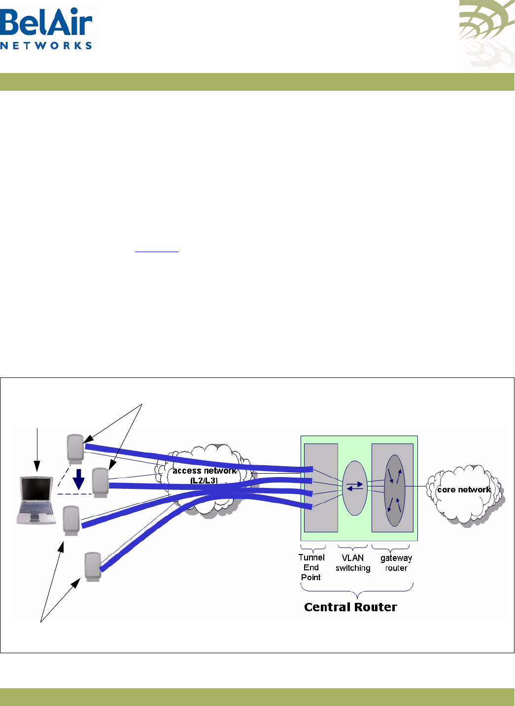
BelAirOS User Guide Using Layer 2 Tunnels
April 22, 2012 Confidential Page 210 of 362
Document Number BDTM00000-A02 Draft
Using Layer 2 Tunnels
Layer 2 tunnels use the Layer 2 Tunneling Protocol (L2TP), version 2, to provide
the following benefits:
• provide a bi-directional communication path between the AP and a central
router. The path is unaffected by the size, topology and complexity of the
Layer 2 and Layer 3 access network between them.
• ensure efficient handling of mobile client MAC addresses, especially for
customers using DOCSIS technology in their access network
Figure 16 shows how wireless mobility is implemented with L2TP. When a
wireless client transmits an 802.11 frame, the AP converts it to an Ethernet
frame with VLAN information, encapsulates it within an IP packet and then
sends the packet to a Tunnel End Point (TEP). The TEP is usually part of a
network central router. The BelAir Networks implementation of Layer 2
tunnels currently operates with a Cisco 7200 router or equivalent, with a
RedBack SmartEdge router or equivalent., with other routers that use Generic
Router Encapsulation (GRE), or with Proxy Mobile IPv4 (PMIP)
implementations.
Figure 16: Wireless Mobility using L2TP
BelAir Networks Access Points (APs)
Mobile wireless client
device going from
one AP to another
BelAir Networks Access Points (APs)

BelAirOS User Guide Using Layer 2 Tunnels
April 22, 2012 Confidential Page 211 of 362
Document Number BDTM00000-A02 Draft
The TEP strips off the encapsulation data to reveal the original Ethernet frame
exactly as sent by the AP. The TEP delivers the Ethernet frame to a
VLAN-aware Ethernet switch. The switch applies normal Ethernet forwarding
rules to send it to a gateway router with one router port per subnet. The
gateway router switches the Ethernet frame to the appropriate outgoing router
port.
For packets moving in the other direction to the wireless client, the gateway
router applies to IP traffic an Ethernet header with the client’s MAC address as
the destination. The VLAN switch forwards this packet to the interface on
which it last saw the client’s MAC address, which is the interface connected to
the tunnel. The TEP receives the frame and encapsulates it in an IP packet.
When the AP receives the packet, it strips off the encapsulation data, converts
the resulting Ethernet frame to an 802.11frame, and then transmits it to the
wireless client.
When a mobile wireless client moves to a new AP, its traffic travels through a
different Layer 2 tunnel. The traffic is encapsulated and sent to TEP as before.
The VLAN-aware Ethernet switch then updates its MAC address table as
required with the information for the wireless client’s new AP. Any subsequent
frames sent to the wireless client are then forwarded to the new AP.
Tunneling is performed by a software module called a
tunnel engine
. APs can
have only one tunnel engine. Each tunnel engine can create up to 10 tunnels to
one or more TEPs. The end points of a Layer 2 tunnel are identified by their IP
addresses. The IP address of the BelAir Networks tunnel end point can be the
IP address of the AP’s management interface, or any IP address associated with
a VLAN. The BelAir Networks IP addresses can be set manually or through the
Dynamic Host Configuration Protocol (DHCP).
Each tunnel can carry traffic belonging to any group of configured VLANs.
By assigning a group name to tunnels, you can also use BelView NMS to do
dynamic load balancing of APs between different LNSs.
Configuring the
AP for Layer 2
Tunneling
The following tasks can be done:
•“Displaying Tunnel Configuration and Status” on page 212
•“Starting and Stopping Layer 2 Tunneling” on page 213
•“Configuring Layer 2 Tunnels” on page 214
•“Setting Tunnel Engine Parameters” on page 214

BelAirOS User Guide Using Layer 2 Tunnels
April 22, 2012 Confidential Page 212 of 362
Document Number BDTM00000-A02 Draft
•“Configuring Tunnel Advanced Parameters” on page 215
•“Enabling Backhaul Protection for Tunnels” on page 216
•“Bandwidth Limits” on page 216
•“Configuring Tunnels for the RedBack SmartEdge Router” on page 217
•“Configuring Tunnels for a Router using GRE” on page 219
•“Configuring Tunnels for PMIP Implementations” on page 220
•“Mapping User Traffic” on page 221
•“Configuring Authentication” on page 222
•“Configuring a Tunnel Group Name” on page 222
•“Relaying Traffic QOS Settings” on page 222
•“Setting the Tunnel Down Alarm Threshold” on page 223
•“Layer 2 Tunnel Performance Monitoring Statistics” on page 223
Layer 2 tunnel CLI commands are available in
/protocol/te-syst
mode.
Displaying Tunnel
Configuration and
Status
/protocol/te-<eng>/show config
/protocol/te-<eng>/show status
These commands display the current tunnel configuration and status.
Example 1
/protocol/te-syst# show config
Tunnel server is running, mode egress, IP address 192.168.219.25 (system), Protection-backhaul:
Disabled
N Type Remote IP Name/Label QoS map State
== ============== =============== ================== ======= =====
1 L2TP 167.206.58.160 tsacm0c none UP
Authentication disabled: Secret N/C, PPP name N/C, PPP pass N/C
L2TP hello: interval 60 sec, retrans count 5, retrans interval 8 sec
PPP echo: interval 10 sec, retrans count 10; DSCP value 0x0
VLAN map: 800
2 N/C
3 N/C
4 N/C
5 N/C
6 N/C
7 N/C
8 N/C
9 N/C

BelAirOS User Guide Using Layer 2 Tunnels
April 22, 2012 Confidential Page 213 of 362
Document Number BDTM00000-A02 Draft
10 N/C
Example 2
/protocol/te-syst# show status
Upstream Downstream Upstream Downstream
N Active Uptime Packets Packets Bytes Bytes Fragmented Reassembled
== ======= ============= ========== ========== ========== ========== ========== ===========
1 Primary 0d 01:02:24 0 1023 0 229497 0 0
Brdcst 0 388
Mltcst 0 12
Up_Exc/Dn_Inv 0 10980
2
3
4
5
6
7
8
9
10
The output of the
show status
command shows:
• which LNS is active at the moment – primary or backup
• tunnel uptime
• number of transmitted and received packets and bytes:
—first line shows total number of packets,
—second line shows the number of MAC broadcasts
—third line shows number of MAC multicasts
• number of packets fragmented/reassembled (due to MTU size)
Starting and Stopping
Layer 2 Tunneling
/protocol/te-<eng>/set engine admin-state {enabled|disabled}
This command starts and stops tunneling operation. Use
enabled
to begin
tunneling operation. Use
disabled
to stop all tunnel forwarding.

BelAirOS User Guide Using Layer 2 Tunnels
April 22, 2012 Confidential Page 214 of 362
Document Number BDTM00000-A02 Draft
Configuring Layer 2
Tunnels
/protocol/te-<eng>/set tunnel <index> ip <peer_IP_addr>
name <stn_name>
[backup-ip <backup_IP_addr> [backup-name <backup_name>]]
[switch {non-revertive | revertive}]
/protocol/te-<eng>/delete tunnel {all|<index>}
The
set tunnel
command creates a new tunnel to be terminated at the specified
peer IP address, which is usually the network central router. You can create up
to 10 tunnels to the same peer or to different peers. Each tunnel carries just
one L2TP session.
The <index> parameter is used for easy reference when using other
commands. It can be displayed with the
/protocol/te-<eng>/show config
command.
The <stn_name> parameter can be any series of 18 alphanumeric ASCII
characters. L2TP protocol provides the <stn_name> parameter to the other
end point so it can identify different tunnels coming from the same IP address
or create logical group of APs with the same name and different IP addresses.
You can optionally specify the IP address and name of a backup server. If a
tunnel cannot be created to the main router or if a tunnel fails, the backup
parameters become active.
The
switch
parameter controls whether the use of a backup router is revertive
or not. Once the AP starts to use a tunnel to a backup router:
• If
switch
is set to
non-revertive
, then the AP uses the tunnel to the backup
router until it fails. Only then does the AP switches back to the tunnel using
the main router. This is the default setting.
• If
switch
is set to
revertive
, then the AP uses the tunnel to the backup
router only while the main tunnel is unavailable. The AP switches back to
the tunnel using the main router as soon as it becomes available again.
The
delete tunnel
command removes all tunnels or the specified tunnel. After
using this command, user data mapped to this tunnel is dropped instead of
forwarded.
Setting Tunnel Engine
Parameters
/protocol/te-<eng>/set mode {local|egress}
[interface-vlan <VLAN_ID>]
The
set mode
command is used when the AP is connected to other APs
through backhaul links. In this case, you may want the AP to act as an egress
point and put access traffic from itself and the other APs into the tunnel. Use
local
mode when the AP puts only its own access traffic into the tunnel. Use

BelAirOS User Guide Using Layer 2 Tunnels
April 22, 2012 Confidential Page 215 of 362
Document Number BDTM00000-A02 Draft
egress
mode when the AP puts its own access traffic and that of many other
APs into the tunnel.
If the VLAN interface is not specified, the AP’s management IP address is used
to identify the local tunnel end point. IP addresses may be manually configured
or obtained by DHCP.
If a VLAN interface is specified, it must be previously configured. Refer to
“Layer 2 Network Configuration” on page 231.
Configuring Tunnel
Advanced Parameters
/protocol/te-<eng>/set tunnel <index> advanced
[l2tp-hello-interval <seconds>]
[l2tp-hello-retrans <number>]
[l2tp-hello-timeout <seconds>]
[ppp-echo-interval <seconds>]
[ppp-echo-retrans <number>]
[dscp-control <hex value>]
The
set tunnel advanced
command lets you specify for particular tunnel timers
and other parameters associated with the L2TP protocol.
The <index> parameter is used for easy reference when using other
commands. It can be displayed with the
/protocol/te-<eng>/show config
command.
The following parameters can be set with this command:
• L2TP Hello transmission interval. Values range from 10 to 300 seconds. The
default setting is 60 seconds.
• L2TP Hello retransmission count. Values range from 1 to 10. The default
setting is 5.
• L2TP Hello retransmission maximum interval. Values range from 1 second
to 32 seconds. The default setting is 8 seconds.
• PPP echo transmission interval. Values range from 0 seconds to
300 seconds. 0 seconds means PPP echo is disabled. The default setting is 10
seconds.
• PPP echo retransmission count. Values range from 1 to 50. The default
setting is 10.
• DSCP value for control (L2TP/PPP) packets. The default setting is 0.
The AP uses the L2TP Hello parameters to determine if the tunnel is available.
If the AP does not receive a Hello packet during the
L2TP Hello transmission
interval
, it begins to send its own Hello packets at exponential intervals starting
at 1 second (that is, at 1, 2, 4, 8, ... seconds) until the
L2TP Hello retransmission

BelAirOS User Guide Using Layer 2 Tunnels
April 22, 2012 Confidential Page 216 of 362
Document Number BDTM00000-A02 Draft
count
and
L2TP Hello retransmission maximum interval
are reached. If none of
the retransmitted Hello packets are answered, then the tunnel is considered
unavailable. For additional details, refer to the L2TP specification.
The PPP echo parameters are also used to determine tunnel availability. PPP
echo packets are sent periodically with the interval specified by the
PPP echo
transmission interval
. The tunnel is considered unavailable if the AP does not
receive consecutive responses for the number of packets specified by the
PPP
echo retransmission count
.
If you specify a DSCP value, then it appears in the DSCP/TOS bits of any L2TP
or PPP control packets.
Enabling Backhaul
Protection for Tunnels
/protocol/te-<eng>/set protection-backhaul {enabled|disabled}
[egress <interface>]
Use this command to inform the tunnel engine that the AP uses egress
protection as described in “Egress Protection” on page 168.
The
egress
parameter applies to BelAir100SN only. It species whether egress is
through the cable modem (cm-9-1) or the Ethernet interface (eth-1-1).
The default setting is
disabled
. Before using this command, make sure all
requirements described in “Egress Protection” on page 168 are met.
When you enable or disable backhaul protection for tunnels, you must:
1 Issue the
config-save
command. See “Saving your Changes” on page 37 for
details.
2 Reboot the AP. See “Activating a Software Load” on page 250 for details.
Bandwidth Limits /protocol/te-<eng>/show limits
/protocol/te-<eng>/set tunnel <index> bandwidth-limit
upstream <bits-per-second>
downstream <bits-per-second>
The
set tunnel bandwidth-limit
command lets you specify for a particular tunnel
the maximum upstream and downstream transmission rates.
The <index> parameter is used for easy reference when using other
commands. It can be displayed with the
/protocol/te-<eng>/show config
command.
The
show limit
command displays the upstream and downstream settings for
the current tunnel.

BelAirOS User Guide Using Layer 2 Tunnels
April 22, 2012 Confidential Page 217 of 362
Document Number BDTM00000-A02 Draft
Example
/protocol/te-syst# show limits
N Us limit Ds limit
== ========== ==========
1 0 0
2
3
4
5
6
7
8
9
10
Configuring Tunnels for
the RedBack SmartEdge
Router
/protocol/te-<eng>/set tunnel-l2vpn <index (1-10)>
oam {enabled | disabled}
{auto | ip <ip_addr> label <number>
[backup-ip <ip_addr>] [backup-label <number>]}
[switch {non-revertive | revertive}]
/protocol/te-<eng>/set l2vpn autoconfig
{ip <ip_addr> | hostname <host_name>}
username <string> password <string>
[retry-min <sec>] [retry-max <sec>]
[wait-time <min>]
/protocol/te-<eng>/l2vpn autoconfig renew
/protocol/te-<eng>/set tunnel-l2vpn <index (1-10)>
advanced inactivity-timer <seconds>
These commands are used to create a tunnel to the central router using
Ethernet-over-MPLS-over-GRE encapsulation instead of L2TP.
Use the
set tunnel-l2vpn
command to create L2VPN tunnels to the specific
destination. L2VPN tunnels may co-exist with regular L2TP tunnels and GRE
tunnels on the same AP.
The
oam
parameter defines if the tunnel uses a failure detection mechanism
based on 802.1ag CCM packets. If
oam
is disabled, the AP considers the tunnel
to always be up. If
oam
is enabled, the AP relies on receiving 802.1ag CCM
packets to detect tunnel state. These packets should be generated by outside
equipment in the head end and should be forwarded to all APs. Set
oam
to
enabled
if you are using backup.
The
auto
parameter tells the AP that it should obtain L2VPN parameters (IP
address and label) from the NetOp NSM server. This is a preferred setting for
large deployments.
The
ip
and
backup-ip
parameters specify IP addresses of the head end tunnel
endpoint. It is usually the IP address of a SmartEdge device terminating L2VPN

BelAirOS User Guide Using Layer 2 Tunnels
April 22, 2012 Confidential Page 218 of 362
Document Number BDTM00000-A02 Draft
tunnels. Use these parameters to manually configure a test environment or
small deployments.
The
label
and
backup-label
parameters specify the MPLS labels of the head end
tunnel endpoint virtual circuit. Use these parameters to manually configure a
test environment or small deployments.
The
switch
parameter controls whether the use of a backup router is revertive
or not. Once the AP starts to use a tunnel to a backup router:
• If
switch
is set to
non-revertive
, then the AP uses the tunnel to the backup
router until it fails. Only then does the AP switches back to the tunnel using
the main router. This is the default setting.
• If
switch
is set to
revertive
, then the AP uses the tunnel to the backup
router only while the main tunnel is unavailable. The AP switches back to
the tunnel using the main router as soon as it becomes available again.
Use the
set l2vpn autoconfig
command to define parameters to communicate
to the NetOp NSM configuration server:
• To specify the NetOp NSM server, supply either the
ip
parameter with an IP
address or the
hostname
parameter with a valid DNS host name.
• The
username
parameter and the
password
parameter are used together to
authenticate the AP with NetOp NSM server.
• The optional
wait-time
parameter lets you specify in minutes how long to
wait for a response from NetOp NSM configuration server before declaring
a failure condition. The default setting is 15 minutes, with a valid range of 1
to 60 minutes.
• The optional
retry-min
and
retry-max
parameters let you specify in seconds
a minimum and maximum value for the retry timer. The value of the retry
timer is chosen randomly within the boundaries defined by the
retry-min
and
retry-max
parameters. The timer is triggered by any failure while trying
to communicate with the NetOp NSM configuration server (for example,
the server not responding in time or the server not recognizing the
username
parameter and the
password
parameters). When timer expires,
the AP attempts to establish communications with the NetOp NSM
configuration server again. The default settings are 60 seconds for
retry-min
and 180 seconds for
retry-max
, with a valid range of 10 to 1800 seconds.
To d i s a b l e
l2vpn autoconfig
, enter an IP address of 0.0.0.0.

BelAirOS User Guide Using Layer 2 Tunnels
April 22, 2012 Confidential Page 219 of 362
Document Number BDTM00000-A02 Draft
Use the
l2vpn autoconfig renew
command to trigger getting a new set of
configuration parameters from the NetOp NSM configuration server.
Use the
set l2vpn advanced inactivity-timer
command to specify how long to
wait until declaring the L2VPN tunnel down. The
<seconds>
parameter ranges
from 10 to 1000 seconds. The default value is 60 seconds.
Configuring Tunnels for
a Router using GRE
/protocol/te-<eng>/set tunnel-gre <index (1-10)>
ip <ip_addr> [proxy-arp {all | list | dhcp}]
/protocol/te-<eng>/set tunnel-gre <index (1-10)>
arp-list <IP_addr> [<IP_addr>]
[<IP_addr>] [<IP_addr>]
[<IP_addr>]
/protocol/te-<eng>/set gre autoconfig ip <IP_addr>
interval <seconds> [port <TCP_port>]
These commands are used to create tunnel to the central router using
IP-over-GRE encapsulation instead of L2TP.
Use the
set tunnel-gre ip
command to create GRE tunnels to the specific
destination. GRE tunnels may co-exist with regular L2TP tunnels and L2VPN
tunnels on the same AP. The
ip
parameter specifies the IP address of the head
end tunnel endpoint. It is usually the IP address of the router terminating GRE
tunnels.
This type of configuration uses proxy ARP because it cannot act as a router to
terminate IP traffic. The
proxy-arp
parameter defines the scope of the proxy
ARP functionality:
•Use
all
if you want to answer ARP requests for any destination IP address.
•Use
dhcp
if you want to answer ARP requests for the default gateway IP
address only. In this case, the gateway IP address is learned from the DHCP
relay communication to the client.
•Use
list
to apply proxy ARP only to traffic destined to a particular set of IP
address. Use the
set tunnel-gre arp-list
command to specify the set of IP
addresses.
The default value of the
proxy-arp
parameter is
all
.
Use the
set gre autoconfig
command to define parameters to communicate to
the third-party heartbeat server using a proprietary protocol. The
ip
parameter
defines the IP address of heartbeat server. To disable this feature, configure the
GRE heartbeat server with ad IP address of 0.0.0.0.
In this configuration, the AP sends a pseudo heartbeat packet at the interval
specified by the
interval
parameter. The
<seconds>
parameter should be at

BelAirOS User Guide Using Layer 2 Tunnels
April 22, 2012 Confidential Page 220 of 362
Document Number BDTM00000-A02 Draft
least 60 seconds. The default value is 60 seconds. The heartbeat server uses
the pseudo heartbeat packet to determine whether the tunnel’s operational
state is up or down. The heartbeat server also uses the pseudo heartbeat
packet to determine the AP’s tunnel configuration and corrects it if required.
The optional
port
parameter specifies the TCP port to communicate with the
heartbeat server. The default value is 4040.
Configuring Tunnels for
PMIP Implementations
/protocol/te-<eng>/set tunnel-pmip <index (1-10)> ha-ip <ip_addr>
secret <string>
spi <number>
[lease-time <seconds>]
/protocol/te-<eng>/set tunnel-pmip <index (1-10)>
advanced dns1 <ip_addr> [dns2 <ip_addr>]
These commands are used to create a Proxy Mobile IPv4 (PMIP) tunnel. A PMIP
tunnel allows a mobile client to change its point-of-attachment to the Internet
without changing its IP address. In this implementation, the network tracks the
movements of the mobile client and initiates the required mobility signalling on
its behalf. In PMIP mode, the AP acts as MIP Foreign Agent.
Use the
set tunnel-pmip ha-ip
command to create a tunnel to a PMIP home
agent. PMIP tunnels may co-exist with regular L2TP tunnels and L2VPN tunnels
on the same AP.
The
ha-ip
parameter specifies the IP address of PMIP Home Agent (HA).
The
secret
parameter specifies the authentication password for access to the
PMIP HA.
The
spi
parameter specifies the index identifying a security context between
the AP and home agent. It is an integer value that should be greater than 255.
The
spi
parameter and the
secret
parameter are used together to authenticate
the AP with the HA.
The optional
lease-time
parameter specifies the maximum lease-time in
seconds for the client session. If the client does not send packets for more than
the specified lease-time, its session is dropped. The default value is
300 seconds.
When client traffic is forwarded through the PMIP tunnel, the AP acts as a
DHCP server and provides all corresponding parameters (such as client's IP
address, subnet mask, gateway, and DNS addresses). The AP proxies all these
parameters from the HA. If the HA is unable to provide some of these

BelAirOS User Guide Using Layer 2 Tunnels
April 22, 2012 Confidential Page 221 of 362
Document Number BDTM00000-A02 Draft
parameters (it must provide at least the client's IP address), the following logic
is used by the AP:
• The subnet mask is determined as corresponding to the IP class by IP
address. For example, for IP address 67.100.125.10 subnet mask is 255.0.0.0.
• The gateway is taken as first address within a specified subnet. For the
previous example, the gateway address is 67.0.0.1. This gateway address is
provided by the AP itself and may not correspond to any real IP address in
the network.
• The DNS IP address(es) are determined by the
set tunnel-pmip advanced
dns
command.
Use the
set tunnel-pmip advanced dns1
command to define the DNS server IP
addresses to be provided to the client by the AP through DHCP in case the AP
can not obtain corresponding settings from the HA. The optional
dns2
parameter specifies the backup DNS server in case the primary one is
unreachable.
Mapping User Traffic /protocol/te-<eng>/map vlan {untagged|<VLAN ID>} to <index>
[domain <string>]
/protocol/te-<eng>/unmap vlan {all|untagged|<VLAN ID>}
The
map vlan
command instructs the tunnel engine to forward traffic to the
specified tunnel. You can specify either traffic associated with a specific VLAN
or traffic that is not tagged for any VLAN. All packets that meet this criteria
received by any of the AP’s radios are forwarded through the tunnel. If the
tunnel is not configured or not active, all corresponding packets are dropped.
If you specify untagged traffic, then the tunnel interface itself must be associated
with a VLAN. Refer to “Setting Tunnel Engine Parameters” on page 214.
The optional
domain
parameter is for PMIP tunnels. Some PMIP
implementations require an additional identification string to communicate with
the PMIP Home Agent (HA). The
domain
parameter allows you to specify the
required string.
The
unmap vlan
command removes all tunnel mapping entries or a specified
tunnel mapping entry. After this command, the specified packets are then
forwarded as if the tunnel does not exist.

BelAirOS User Guide Using Layer 2 Tunnels
April 22, 2012 Confidential Page 222 of 362
Document Number BDTM00000-A02 Draft
Configuring
Authentication
/protocol/te-<eng>/set tunnel <index (1-10)>
[secret <shared_secret>]
[ppp-name <id>] [ppp-password <pw>]
[backup-secret <backup_shared_secret>]
[backup-ppp-name <backup_id>] [backup-ppp-password <backup_pw>]
/protocol/te-<eng>/set tunnel <index (1-10)>
authentication {enabled|disabled}
The
set secret
command configures the parameters for L2TP authentication for
a specified tunnel. The
secret
parameter sets the shared secret for tunnel
authentication. The
ppp-name
and
ppp-password
parameters set the data for
session authentication. The settings for each of these three parameters must
match the equivalent settings on the main router.
The
backup-secret
,
backup-ppp-name
and
backup-ppp-password
parameters
are equivalent settings for a backup router.
Once the authentication parameters are configured, you use the
set
authentication
command to enable authentication for a specified tunnel.
Configuring a Tunnel
Group Name
/protocol/te-<eng>/set tunnel <index (1-10)>
group-name <group_name>
The <group_name> parameter indicates that an LNS belongs to a particular
group.
The BelView NMS tunnel manager looks at the tunnel usage of all LNSs within
the same group and spread the tunnel traffic among the LNSs within the same
group. BelView also configures tunnels for newly introduced APs to the least
used LNS within the same group.
For details, refer to the
BelView NMS User Guide
.
Relaying Traffic QOS
Settings
/protocol/te-<eng>/set tunnel <index (1-10)>
qos-map {none|up-bits|dscp)
Because the AP converts the client data packet into an Ethernet frame and then
encapsulates it within an IP packet, any QOS information that was part of the
original client data packet is not visible to upstream equipment.
This command allows you to put the QOS information into the encapsulating IP
packet header so that it becomes visible to the upstream equipment:
• The
dscp
setting means that Differentiated Services Code Point (DSCP)
information from the client data packet is included in the IP packet header.
• The
up-bits
settings means that the IP packet header contains QOS settings
based on User Priority bits (0 to 7) from the client data packet.

BelAirOS User Guide Using Layer 2 Tunnels
April 22, 2012 Confidential Page 223 of 362
Document Number BDTM00000-A02 Draft
• The
none
setting means that QOS information from the client data packet is
not sent to upstream equipment.
The default setting is
none
.
Setting the Tunnel
Down Alarm Threshold
/protocol/te-<eng>/set alarm-threshold
{disabled | enabled <num_of_alarms>}
Typ i c a l ly, a
Tunnel Down
alarm is generated when a tunnel fails to respond.
However, if there are intermittent issues with the tunnel, it may take time to
identify and correct the root cause. During this period, multiple
Tunnel Down
alarms would be generated.
Enabling the alarm threshold reduces the number of
Tunnel Down
alarms
generated per calendar day. If the threshold is reached, the system generates
instead a single
Excess Tunnel Down Events
alarm and stops generating
additional
Tunnel Down
alarms. The
Tunnel Down
events are still tracked
through the tunnel’s performance monitoring statistics, allowing you to analyze
the behavior.
The
<num_of_alarms>
parameter ranges from 2 to 50. By default, the alarm
threshold is enabled with a setting of
5
, meaning that the
Excess Tunnel Down
Events
alarm is generated once 5
Tunnel Down
events occur in a day.
Alarms generated during a maintenance window do not count against the alarm
threshold. For details see, “Defining a Maintenance Window” on page 75.
Layer 2 Tunnel
Performance
Monitoring Statistics
/protocol/te-<eng>/show tunnel <index (1-5)> pm {fifteen-min|day}
[{{<0-96>|<0-7>} |
all {total|average|ppp}}]
This command displays a Layer 2 tunnel’s performance measurements either for
a specific time interval or for a series of time intervals. The valid parameter
options are:
•
fifteen-min
,
fifteen-min 0
to
fifteen-min 96
•
day
,
day 0
to
day 7
•
all
, all performance measurements. If you specify
all
you need to specify
whether you want the total of all measurements, the average of all
measurements or all PPP measurements.
Specifying
fifteen-min
is equivalent to specifying
fifteen-min 0
and means the
current 15-minute interval. Specifying
day
is equivalent to specifying
day 0
and
means the current day, excluding data from the current 15-minute period.

BelAirOS User Guide Using Layer 2 Tunnels
April 22, 2012 Confidential Page 224 of 362
Document Number BDTM00000-A02 Draft
The output displays Unavailable Seconds statistics for that interval. The counter
does not start incrementing until the tunnel has been unavailable for
60 seconds.
Example
/protocol/te-syst# show tunnel 1 pm fifteen-min
Interval type : current 15 minute
Interval number : 0 (193)
Unavailable Seconds : 0
Tunnel Down Events : 0
--- User Data Stats ---
Up : Total Sec Down : Total Sec
Pkts : 34 ( 0) Pkts : 1056 ( 5)
Bytes : 9095 ( 47) Bytes : 74713 ( 387)
Brdcst : 0 ( 0) Brdcst : 1015 ( 5)
Mltcst : 0 ( 0) Mltcst : 0 ( 0)
Excess : 0 ( 0) Invalid : 272 ( 1)
Frag : 0 ( 0) Reass : 0 ( 0)
--- PPP Echo Stats ---
ReqRecvd: 20
ReqSend: 20 RespRecvd: 20 % Lost: 0
Lost - 1 to 5: 0 6 to 10: 0 > 10: 0
Configuring the
Network Central
Router for
Layer 2 Tunneling
The specific configuration tasks and commands for the network central router
vary, depending on the type of router that is installed.
Refer to the
Tunnel Mobility Technical Bulletin
, available at
www.support.belairnetworks.com for guidance on configuring the router
portion of the tunnels.

BelAirOS User Guide Quality of Service Settings
April 22, 2012 Confidential Page 225 of 362
Document Number BDTM00000-A02 Draft
Quality of Service Settings
The AP includes Quality of Service (QoS) settings for the following functional
areas:
• traffic switching. See “System QoS” on page 225.
• client to access point radio communications. See “Radio QoS” on page 228.
System QoS BelAir Networks APs work in conjunction with one another to allow you to
separate and prioritize traffic. Each AP can inspect incoming traffic and
prioritize traffic into four priority queues.
Prioritization Each AP supports four traffic priority queues, numbered 0 to 3. Queue 3 has
the highest priority while queue 0 has the lowest priority. Table 14 describes
each queue.
All traffic that is not associated to a VLAN has priority 1. This means that until
you create VLANs, all traffic has priority 1.
Once VLANs have been created, you configure the AP traffic to have different
priorities based on User Priority bits (0 to 7) or VLAN IDs.
Table 14: Traffic Priority Queues
Queue
Number Description
0 Background traffic
1 Best effort traffic
Use this queue for traffic that does not require QoS features,
such as most data traffic
2 Video traffic, T1 circuit emulation
Use this queue for high priority traffic such as T1 circuit
emulation, video or “gold service” customer traffic
3 Voice over IP (VoIP) traffic
Use this queue for SVP or other VoIP applications

BelAirOS User Guide Quality of Service Settings
April 22, 2012 Confidential Page 226 of 362
Document Number BDTM00000-A02 Draft
The prioritization commands (
map
and
no map)
described in this chapter apply
strictly to the AP that you are currently logged on to. You must repeat them on
each related AP. For example, when specifying that particular VLAN traffic has a
particular priority, you must execute the associated commands on each
possible AP in the path of that VLAN.
Prioritizing Traffic Based
on User Priority Bits
/qos/set up-to-queue-mapping <priority> <queue_id>
This command instructs the AP to process packets with the specified User
Priority value to the specified priority queue. The
priority
parameter ranges
from 0 to 7. The
queue_id
parameter ranges from 0 to 3, as described in
Table 14 on page 225.
Note: Settings made with the
set vlan-to-queue-mapping
command have
precedence over settings made with this command.
Table 15 shows how User Priority values are processed to priority queues by
default.
To unmap a previously set priority, use the
set up-to-queue-mapping
command
to map that priority back to the default priority queue as shown in Table 15.
Prioritizing Traffic using
VLAN IDs
/qos/set vlan-to-queue-mapping <vlan_id> {none|<queue_id>}
/qos/show vlan {all|id <vlan_id>}
The
set
command instructs the AP to process packets from the specified VLAN
to the specified priority queue. The
vlan_id
parameter ranges from 1 to 3015
Table 15: User Priority Value to Priority Queue Processing
User Priority Value Priority Queue to which it is processed
01
10
20
3 1
42
52
63
73

BelAirOS User Guide Quality of Service Settings
April 22, 2012 Confidential Page 227 of 362
Document Number BDTM00000-A02 Draft
and from 3018 to 4045. The
queue_id
parameter ranges from 0 to 3, as
described in Table 14 on page 225. The
none
parameter removes the mapping
of a VLAN ID to priority queue.
Note: Settings made with this command have precedence over settings made
with the
set up-to-queue-mapping
command.
The
show
command displays a summary of the QoS settings that are based on
VLAN IDs.
Example
/qos# show vlan id 100
Qos Vlan Id Configuration
------------------------
Vlan Id : 100
------------------------
Vlan Qos Status : Enabled
Queue Map : 3
Resetting the QoS
Configuration
/qos/set defaults
This command returns the system QoS configuration to factory default
settings.
Note: This command does not affect radio QoS configuration.
Displaying a Summary of
System QoS Settings
/qos/show config
This command displays a summary of all current QOS settings, including how
User Priority bits are currently mapped to the priority queues.
Example
/qos# show config
Qos Global Configuration
------------------------
Qos Status : Enabled
Qos Global UP to Queue Mapping
---------------------------------
UP Value : 0 -- Queue : 1
UP Value : 1 -- Queue : 0
UP Value : 2 -- Queue : 0
UP Value : 3 -- Queue : 1
UP Value : 4 -- Queue : 2
UP Value : 5 -- Queue : 2
UP Value : 6 -- Queue : 3
UP Value : 7 -- Queue : 3

BelAirOS User Guide Quality of Service Settings
April 22, 2012 Confidential Page 228 of 362
Document Number BDTM00000-A02 Draft
No Vlan based Qos Configured!
-----------------------------
Displaying the
Prioritization Settings
/qos/show user-priority-map
The
show user-priority-map
command displays how User Priority bits are
currently mapped to the priority queues.
Example
/qos# show user-priority-map
Qos Global UP to Queue Mapping
---------------------------------
UP Value : 0 -- Queue : 1
UP Value : 1 -- Queue : 0
UP Value : 2 -- Queue : 0
UP Value : 3 -- Queue : 1
UP Value : 4 -- Queue : 2
UP Value : 5 -- Queue : 2
UP Value : 6 -- Queue : 3
UP Value : 7 -- Queue : 3
Radio QoS BelAir Networks radios offer Wireless Multi-Media (WMM) support for
multiple priority packets and transmit opportunities. This allows over-the-air
QoS for WMM client devices with faster burst transfer. (Use the
/mode
command to see the version number of your radio modules.)
Some WMM features, such as selecting the priority scheme and the mapping
scheme, are also available for BelAir Networks backhaul radios to provide
end-to-end QoS functionality.
Displaying a Summary of
Radio QoS Settings Use the
/interface/wifi-<n>-<m>/show config qos
command to display the
current radio QoS settings. See “Displaying Wi-Fi Radio Configuration” on
page 104 for details.
Example - BelAir20E
/interface/wifi-1-1# show config qos
Slot: 1, Card Type: htme, revision: 1, Port: 1, Radio: HTMv1 5GHz
802.11n
admin state: ................. Enabled
channel: ..................... 149
mode: ...................... ht40plus
mimo: ...................... 3x3
tx power: .................. 18.0 (dBm per-chain), 23.0 (dBm total)
antenna location: ............ External Port
antenna index: ............... 1
antenna gain: ................ 5.0 (dBi)
link distance: ............... 1 (km)
base radio MAC : ............. 00:0d:67:0c:21:90

BelAirOS User Guide Quality of Service Settings
April 22, 2012 Confidential Page 229 of 362
Document Number BDTM00000-A02 Draft
QOS:
wmm: ....................... Enabled
uapsd: ..................... Enabled
mapping: ................... UP/DSCP
voice acm: ................. Disabled
video acm: ................. Disabled
Enabling or Disabling
Wireless Multi-media
/interface/wifi-<n>-<m>/set qos wmm {enable|disable}
Wireless Multi-media is normally enabled. It allows the access point to
communicate with a WMM enabled wireless client using WMM features.
When disabled, the access point ignores requests for WMM communications
from wireless clients and instead uses traditional non-WMM features to
communicate with them. To disable WMM, you must first disable Unscheduled
Automatic Power-save Delivery (UAPSD). See “Unscheduled Automatic
Power-save Delivery” on page 230.
QoS Mapping Scheme /interface/wifi-<n>-<m>/set qos mapping {up|dscp|both}
The
set
command lets you decide how traffic is processed to the four priority
queues depending on the values of the User Priority (UP) field or the
Differentiated Services Code Point (DSCP) subfield in the client traffic fields.
Selecting
up
means that traffic is sent to the four priority queues based on the
UP field value. Selecting
dscp
means that traffic is sent to the four priority
queues based on the DSCP subfield value. Selecting
both
means that traffic is
sent to the four priority queues based on the highest priority value of either
the UP field or the DSCP subfield. By default, QoS mapping is set to
both
.
Table 16 shows the mapping of the UP value and the DSCP value to the priority
queue.
Table 16: UP and DSCP Value to Priority Queue Processing
UP Value DSCP Value Target Priority Queue
0 0 (0x0) 1
1 32 (0x20) 0
2 64 (0x40) 0
3 96 (0x60) 1
4 128 (0x80) 2
5 160 (0xA0) 2

BelAirOS User Guide Quality of Service Settings
April 22, 2012 Confidential Page 230 of 362
Document Number BDTM00000-A02 Draft
Unscheduled Automatic
Power-save Delivery
/interface/wifi-<n>-<m>/set qos uapsd {enable|disable}
Unscheduled Automatic Power-save Delivery (UAPSD) extends the battery life
of wireless clients and reduces radio transmission traffic. To enable UAPSD, you
must first enable Wireless Multi-media (WMM) for the radio. Refer to
“Enabling or Disabling Wireless Multi-media” on page 229.
This command lets you enable or disable UAPSD. By default, UAPSD is enabled.
6 192 (0xC0) 3
7 224 (0xE0) 3
Table 16: UP and DSCP Value to Priority Queue Processing
UP Value DSCP Value Target Priority Queue

BelAirOS User Guide Layer 2 Network Configuration
April 22, 2012 Confidential Page 231 of 362
Document Number BDTM00000-A02 Draft
Layer 2 Network Configuration
The AP acts as a transparent bridge and layer 2 switch without the need to
configure any software features. However, to control and manage the traffic
inherent in a bridge (for example, broadcast and flooding) and to handle loop
situations where multiple paths exist between APs, you can invoke layer 2
features such as:
• Virtual LANs (VLANs), that divide traffic among several sets of users and
restrict broadcast to the respective VLANs. See “Configuring IP
Parameters” on page 62.
• Spanning Tree Protocol (STP), where the optimum path is selected and
ports of alternate paths are shutdown
If there are no loops in the network, the AP can operate in bridge mode or
with VLANs. If a loop exists, STP must be invoked to manage the different
paths.
This chapter contains the following sections:
•“Spanning Tree Protocol Overview” on page 231
—“Configuring Spanning Tree Priority” on page 232
—“Configuring Other Spanning Tree Parameters” on page 233
—“RSTP Commands” on page 234
See also “Managing Egress AP Traffic” on page 92.
Spanning Tree
Protocol
Overview
It is important to configure the Spanning Tree Protocol (STP) when multiple
paths between APs are created. As networks become more complex, multiple
paths between APs, either intentional or unintentional, become more likely.
Although loops benefit the network by providing path redundancy, loops must
be dynamically eliminated to prevent proliferation of broadcast traffic and
confusion in the MAC learning tables of the bridge. This is accomplished by a
spanning tree protocol, which generates a loop-free subset of the network's
topology by placing those bridge or switch ports that, if active, would create
loops into a standby (blocking) condition. Blocked bridge or switch ports can
be activated in the event of primary link failure, providing a new path through
the network.

BelAirOS User Guide Layer 2 Network Configuration
April 22, 2012 Confidential Page 232 of 362
Document Number BDTM00000-A02 Draft
Loops can also occur accidentally or maliciously. For example, a technician may
connect their laptop to the Ethernet port of an AP and also have a wireless link
to an AP in the same network. If the laptop is configured to act as a bridge then
it creates a loop in the network, and broadcast traffic quickly proliferates until
the slowest link in the loop is saturated. This broadcast storm renders part—or
all—of the network unusable.
Note: To prevent issues as described previously, clients that associate with the
AP are not allowed to operate as a bridge. The AP will automatically
disassociate without warning from any client that is detected as
behaving as a bridge; that is, sending spanning-tree BPDUs. However,
clients are allowed to operate as router to allow features such as
sharing a wireless Internet connection. For this type of operation,
BelAir Networks recommends that the computer with the wireless
connection to the AP have its operating system configured to act as a
router. For example, Microsoft Windows XP offers the
Internet Sharing
function.
The original spanning tree protocol is STP. When STP detects a topology
change in the network, STP blocks all user traffic, creates a new loop-free
configuration, and then re-enables user traffic. STP reconfigurations create
outages that are typically 30 to 60 seconds in length.
A newer protocol, Rapid STP (RSTP), greatly reduces the length of outages
caused by topology reconfigurations. RSTP is backwards compatible with STP
so it can be used in networks where some equipment only supports STP.
APs are shipped from the factory with RSTP enabled and default settings that
are a suitable starting point for most deployments. The default AP priority is
36864 (or 0x9000). The default port settings vary depending on the hardware
in use, the topology and whether dynamic path cost is used or not.
You should adjust the STP AP priority and path cost settings for each AP to
match the topology of your network. Refer to your network plan
for details.
Configuring Spanning
Tree Priority If all APs are enabled with default settings, the switch with the lowest MAC
address in the network becomes the root switch. However, due to traffic
patterns, number of forwarding ports, or line types, the AP with the lowest
MAC address might not be the ideal root switch. By increasing the priority
(lowering the numerical priority number) of the ideal switch so that it becomes
the root switch, an STP recalculation will be done to form a new topology.
BelAir Networks recommends that the root AP is the Ethernet switch that is
used to connect to the LIM(s).

BelAirOS User Guide Layer 2 Network Configuration
April 22, 2012 Confidential Page 233 of 362
Document Number BDTM00000-A02 Draft
Refer to your network plan for details.
Use the command described in “RSTP Priority” on page 240 and “RSTP
Version” on page 240 to specify the STP priority and the version of STP used by
the AP.
Configuring Other
Spanning Tree
Parameters
Table 17 describes spanning tree parameters that you can configure in addition
to the STP AP priority and path cost.
Table 17: Configurable Spanning Tree Timers and Associated Parameters
Parameter Default
Value Description Possible Range
Hello Timer 2 s Determines how often
the bridge broadcasts
hello messages to other
bridges
1 s to 10 s
Must be less than
or equal to:
(1/2Max_Age - 1)
Forward
Delay Timer
15 s Determines how long
each of the listening and
learning states last before
the interface begins
forwarding
4 s to 30 s
Must not be less
than:
(1/2Max_Age + 1)
Maximum
Age Timer
20 s Determines the amount
of time the bridge stores
protocol information
received on an interface
6 s to 40 s
Must not be less
than:
2(Hello_timer + 1)
Must not exceed:
2(Forward_Delay - 1)
Tran sm it
Hold Count
6 Transmit hold count
(packet queue length)
1 to 10
Path Cost
Typ e
32 bit Represents the media
speed (or bit rate)
16 bit or 32 bit

BelAirOS User Guide Layer 2 Network Configuration
April 22, 2012 Confidential Page 234 of 362
Document Number BDTM00000-A02 Draft
Note: BelAir Networks recommends that you do not change the RSTP
parameter values in Table 17 from their default values. Experience has
shown that these default values work well in a variety of networks.
To change the spanning tree transmit hold count and the path cost, refer to
“Transmit Hold Count” on page 240.
To change the values of the spanning-tree timers, refer to “Max Age, Hello
Time and Forward Delay” on page 241.
Note: The STP or RSTP parameter values that are actually used are inherited
from the root bridge. When you configure STP or RSTP parameters on
an AP, you are setting the values that are used if that AP is the root
bridge.
RSTP Commands This section describes commands that you can execute while in
rstp
mode.
Some RSTP commands apply to specific physical interfaces or to specific radio
links. The
Name
column of the
/protocol/rstp/show config port all
command
displays available interfaces and radio links. For example, if the
Name
column
displays
wifi-3-1-1
, then
wifi-3-1
identifies the interface and the
-1
suffix
identifies radio link 1 of that interface.
The AP layer 2 switch forwards layer 2 frames to the output of one or more
physical interfaces or radio links based on the information contained in the
frame header (tags).
Displaying the RSTP
Configuration Settings
/protocol/rstp/show config [port {all|active|<interface-name>}]
This command displays the currently configured RSTP settings. To see the
currently active RSTP parameters, as inherited from the root bridge, use the
/protocol/rstp/show config port active
command.
Link
Detection
Count
3 Represents the number
Hello timer periods to
wait before declaring the
link is down
3 to the ratio of the
Maximum Age
timer to the Hello
timer
Table 17: Configurable Spanning Tree Timers and Associated Parameters
Parameter Default
Value Description Possible Range

BelAirOS User Guide Layer 2 Network Configuration
April 22, 2012 Confidential Page 235 of 362
Document Number BDTM00000-A02 Draft
Specifying the
port
keyword displays RSTP configuration settings for each
physical interface and radio link. Use the
<interface-name>
parameter to
specify a particular interface and radio link, as shown under the
Name
column of
the
/protocol/rstp/show config port all
command.
Example 1
/protocol/rstp# show config
RSTP Configurations
--------------------
Rstp Status : Enabled
Stp priority : 36864
Stp Version : Rstp Mode
Bridge Max Age : 20 seconds
Bridge Hello Time : 2 seconds
Bridge Forward Delay Time : 15 seconds
Tx Hold Count : 3
Link Detection Count : 3
Bridge Address : 00:0d:67:00:69:d4
Bridge Aging Time : 300
---------------------------------------
Example 2
/protocol/rstp# show config port all
RSTP Port Configurations
--------------------
Port Name Prio Pathcost Migration Edge P2P Protocol Dynamic-Cost
Interface-link Conf/Oper Conf/Oper Version Status Default
---- -------------- ---- ---------- --------- ------------ ------------- -------- -----------------
1 wifi-1-1-1 128 830768 False False/False True/True RSTP Enabled 830769
2 wifi-1-1-2 128 2000000 False False/False True/False RSTP Enabled 830769
3 wifi-1-1-3 128 2000000 False False/False True/False RSTP Enabled 830769
4 wifi-1-1-4 128 2000000 False False/False True/False RSTP Enabled 830769
5 wifi-1-1-5 128 2000000 False False/False True/False RSTP Enabled 830769
6 wifi-1-1-6 128 2000000 False False/False True/False RSTP Enabled 830769
7 wifi-1-1-7 128 2000000 False False/False True/False RSTP Enabled 830769
8 wifi-1-1-8 128 2000000 False False/False True/False RSTP Enabled 830769
9 wifi-2-1-1 128 2000000 False False/False True/False RSTP Enabled 3000000
10 wifi-2-1-2 128 2000000 False False/False True/False RSTP Enabled 3000000
11 wifi-2-1-3 128 2000000 False False/False True/False RSTP Enabled 3000000
12 wifi-2-1-4 128 2000000 False False/False True/False RSTP Enabled 3000000
13 wifi-2-1-5 128 2000000 False False/False True/False RSTP Enabled 3000000
14 wifi-2-1-6 128 2000000 False False/False True/False RSTP Enabled 3000000
15 wifi-2-1-7 128 2000000 False False/False True/False RSTP Enabled 3000000
16 wifi-2-1-8 128 2000000 False False/False True/False RSTP Enabled 3000000
17 wifi-3-1-1 128 3187500 False False/False True/True RSTP Enabled 3000000
18 wifi-3-1-2 128 2000000 False False/False True/False RSTP Enabled 3000000
19 wifi-3-1-3 128 2000000 False False/False True/False RSTP Enabled 3000000
20 wifi-3-1-4 128 2000000 False False/False True/False RSTP Enabled 3000000
21 wifi-3-1-5 128 2000000 False False/False True/False RSTP Enabled 3000000

BelAirOS User Guide Layer 2 Network Configuration
April 22, 2012 Confidential Page 236 of 362
Document Number BDTM00000-A02 Draft
22 wifi-3-1-6 128 2000000 False False/False True/False RSTP Enabled 3000000
23 wifi-3-1-7 128 2000000 False False/False True/False RSTP Enabled 3000000
24 wifi-3-1-8 128 2000000 False False/False True/False RSTP Enabled 3000000
25 wifi-4-1-1 128 2000000 False False/False True/True RSTP Enabled 2000000
26 wifi-4-1-2 128 2000000 False False/False True/False RSTP Enabled 2000000
27 wifi-4-1-3 128 2000000 False False/False True/False RSTP Enabled 2000000
28 wifi-4-1-4 128 2000000 False False/False True/False RSTP Enabled 2000000
29 wifi-4-1-5 128 2000000 False False/False True/False RSTP Enabled 2000000
30 wifi-4-1-6 128 2000000 False False/False True/False RSTP Enabled 2000000
31 wifi-4-1-7 128 2000000 False False/False True/False RSTP Enabled 2000000
32 wifi-4-1-8 128 2000000 False False/False True/False RSTP Enabled 2000000
33 eth-5-1 128 200000 False False/False True/True RSTP Disabled 200000
Example 3
/protocol/rstp# show config port wifi-2-1-1
RSTP Port Configurations
--------------------
Port Name Prio Pathcost Migration Edge P2P Protocol Dynamic-Cost
Interface-link Conf/Oper Conf/Oper Version Status Default
---- -------------- ---- ---------- --------- ------------ ------------- -------- -----------------
9 wifi-2-1-1 128 2000000 False False/False True/False RSTP Enabled 3000000
Example 4
/protocol/rstp# show config port active
RSTP Port Configurations
--------------------
Port Name Prio Pathcost Migration Edge P2P Protocol Dynamic-Cost
Interface-link Conf/Oper Conf/Oper Version Status Default
---- -------------- ---- ---------- --------- ------------ ------------- -------- -----------------
1 wifi-1-1-1 128 830768 False False/False True/True RSTP Enabled 830769
17 wifi-3-1-1 128 3187500 False False/False True/True RSTP Enabled 3000000
25 wifi-4-1-1 128 2000000 False False/False True/True RSTP Enabled 2000000
33 eth-5-1 128 200000 False False/False True/True RSTP Disabled 200000
Displaying the RSTP
Topology Information
/protocol/rstp/show topology [port {all|active|<interface-name>}]
This command displays the currently active RSTP parameters as inherited from
the root bridge, including the MAC address of the designated root bridge in a
network, the cost of the path to the root, the port used to message to the root
bridge, as well as the current values of the spanning tree timers.
To see the currently configured RSTP parameters, use the
/protocol/rstp/show
config
command.

BelAirOS User Guide Layer 2 Network Configuration
April 22, 2012 Confidential Page 237 of 362
Document Number BDTM00000-A02 Draft
In the resulting output when the
port
keyword is omitted,
Root Cost
reflects
the AP's cost to root that it would advertise in its BPDUs sent out to
designated or alternate ports.
Specifying the
port
keyword displays per port RSTP topology information for
each physical interface and radio link. Use the
<interface-name>
parameter to
specify a particular interface and radio link, as shown under the
Name
column of
the
/protocol/rstp/show config port all
command.
In the resulting output when the
port
keyword is used,
Designated Cost
is the
minimum port cost seen in BPDUs on that link (either from the AP itself or
from another AP on that same link).
Example 1
/protocol/rstp# show topology
RSTP Topology Information
--------------------
Designated Root : 00:00:00:12:00:32:9d:80
Stp Root Cost : 4000000
Stp Root Port : 33
Stp Max Age : 31 seconds
Stp Hello Time : 1 seconds
Stp Forward Delay Time : 21 seconds
---------------------------------------
Example 2
/protocol/rstp# show topology port all
RSTP Port Topology Information
-------------------------------
Port Name Designated-root Designated Designated-bridge Designated
Interface-link Cost Port
---- -------------- ----------------------- ---------- ----------------------- ----------
1 wifi-1-1-1 60:00:00:23:34:b0:3e:80 200000 90:00:00:0d:67:00:69:5e 80:01
2 wifi-1-1-2 00:00:00:00:00:00:00:00 0 00:00:00:00:00:00:00:00 00:00
3 wifi-1-1-3 00:00:00:00:00:00:00:00 0 00:00:00:00:00:00:00:00 00:00
4 wifi-1-1-4 00:00:00:00:00:00:00:00 0 00:00:00:00:00:00:00:00 00:00
5 wifi-1-1-5 00:00:00:00:00:00:00:00 0 00:00:00:00:00:00:00:00 00:00
6 wifi-1-1-6 00:00:00:00:00:00:00:00 0 00:00:00:00:00:00:00:00 00:00
7 wifi-1-1-7 00:00:00:00:00:00:00:00 0 00:00:00:00:00:00:00:00 00:00
8 wifi-1-1-8 00:00:00:00:00:00:00:00 0 00:00:00:00:00:00:00:00 00:00
9 wifi-2-1-1 00:00:00:00:00:00:00:00 0 00:00:00:00:00:00:00:00 00:00
10 wifi-2-1-2 00:00:00:00:00:00:00:00 0 00:00:00:00:00:00:00:00 00:00
11 wifi-2-1-3 00:00:00:00:00:00:00:00 0 00:00:00:00:00:00:00:00 00:00
12 wifi-2-1-4 00:00:00:00:00:00:00:00 0 00:00:00:00:00:00:00:00 00:00

BelAirOS User Guide Layer 2 Network Configuration
April 22, 2012 Confidential Page 238 of 362
Document Number BDTM00000-A02 Draft
13 wifi-2-1-5 00:00:00:00:00:00:00:00 0 00:00:00:00:00:00:00:00 00:00
14 wifi-2-1-6 00:00:00:00:00:00:00:00 0 00:00:00:00:00:00:00:00 00:00
15 wifi-2-1-7 00:00:00:00:00:00:00:00 0 00:00:00:00:00:00:00:00 00:00
16 wifi-2-1-8 00:00:00:00:00:00:00:00 0 00:00:00:00:00:00:00:00 00:00
17 wifi-3-1-1 60:00:00:23:34:b0:3e:80 200000 90:00:00:0d:67:00:69:5e 80:11
18 wifi-3-1-2 00:00:00:00:00:00:00:00 0 00:00:00:00:00:00:00:00 00:00
19 wifi-3-1-3 00:00:00:00:00:00:00:00 0 00:00:00:00:00:00:00:00 00:00
20 wifi-3-1-4 00:00:00:00:00:00:00:00 0 00:00:00:00:00:00:00:00 00:00
21 wifi-3-1-5 00:00:00:00:00:00:00:00 0 00:00:00:00:00:00:00:00 00:00
22 wifi-3-1-6 00:00:00:00:00:00:00:00 0 00:00:00:00:00:00:00:00 00:00
23 wifi-3-1-7 00:00:00:00:00:00:00:00 0 00:00:00:00:00:00:00:00 00:00
24 wifi-3-1-8 00:00:00:00:00:00:00:00 0 00:00:00:00:00:00:00:00 00:00
25 wifi-4-1-1 60:00:00:23:34:b0:3e:80 200000 90:00:00:0d:67:00:69:5e 80:19
26 wifi-4-1-2 00:00:00:00:00:00:00:00 0 00:00:00:00:00:00:00:00 00:00
27 wifi-4-1-3 00:00:00:00:00:00:00:00 0 00:00:00:00:00:00:00:00 00:00
28 wifi-4-1-4 00:00:00:00:00:00:00:00 0 00:00:00:00:00:00:00:00 00:00
29 wifi-4-1-5 00:00:00:00:00:00:00:00 0 00:00:00:00:00:00:00:00 00:00
30 wifi-4-1-6 00:00:00:00:00:00:00:00 0 00:00:00:00:00:00:00:00 00:00
31 wifi-4-1-7 00:00:00:00:00:00:00:00 0 00:00:00:00:00:00:00:00 00:00
32 wifi-4-1-8 00:00:00:00:00:00:00:00 0 00:00:00:00:00:00:00:00 00:00
33 eth-5-1 60:00:00:23:34:b0:3e:80 0 60:00:00:23:34:b0:3e:80 80:0f
Example 3
/protocol/rstp# show topology port wifi-2-1-1
RSTP Port Topology Information
-------------------------------
Port Name Designated-root Designated Designated-bridge Designated
Interface-link Cost Port
---- -------------- ----------------------- ---------- ----------------------- ----------
9 wifi-2-1-1 00:00:00:00:00:00:00:00 0 00:00:00:00:00:00:00:00 00:00
Example 4
/protocol/rstp# show topology port active
RSTP Port Topology Information
-------------------------------
Port Name Designated-root Designated Designated-bridge Designated
Interface-link Cost Port
---- -------------- ----------------------- ---------- ----------------------- ----------
1 wifi-1-1-1 60:00:00:23:34:b0:3e:80 200000 90:00:00:0d:67:00:69:5e 80:01
17 wifi-3-1-1 60:00:00:23:34:b0:3e:80 200000 90:00:00:0d:67:00:69:5e 80:11
25 wifi-4-1-1 60:00:00:23:34:b0:3e:80 200000 90:00:00:0d:67:00:69:5e 80:19
33 eth-5-1 60:00:00:23:34:b0:3e:80 0 60:00:00:23:34:b0:3e:80 80:0f

BelAirOS User Guide Layer 2 Network Configuration
April 22, 2012 Confidential Page 239 of 362
Document Number BDTM00000-A02 Draft
Displaying RSTP Port
Roles and States
/protocol/rstp/show port roles [all]
This command displays the roles and states of the RSTP ports.
Specifying the
all
option displays all possible links for a specific interface. If the
all
option is omitted, then the command outputs data only for links with a
status of
UP
.
Example 1
/protocol/rstp# show port roles
RSTP Port Roles and States
---------------------------
Port# Name Remote-id Port-Role Port-State Port-Status
----- ----------- --------------- ---------- ---------- ---------
9 wifi-2-1-1 10.5.1.22 Designated Forwarding Enabled
11 wifi-2-1-3 10.5.1.10 Designated Forwarding Enabled
17 wifi-3-1-1 10.5.1.13 Designated Forwarding Enabled
18 wifi-3-1-2 10.5.1.14 Designated Forwarding Enabled
25 wifi-4-1-1 10.5.1.25 Designated Forwarding Enabled
33 eth-1-1 Root Forwarding Enabled
34 eth-1-2 Designated Forwarding Enabled
Example 2
/protocol/rstp# show port roles all
RSTP Port Roles and States
---------------------------
Port# Name Remote-id Port-Role Port-State Port-Status Link-status
----- ----------- --------------- ---------- ---------- --------- ------------
1 wifi-1-1-1 Disabled Discarding Enabled Down
2 wifi-1-1-2 Disabled Discarding Enabled Down
3 wifi-1-1-3 Disabled Discarding Enabled Down
4 wifi-1-1-4 Disabled Discarding Enabled Down
5 wifi-1-1-5 Disabled Discarding Enabled Down
6 wifi-1-1-6 Disabled Discarding Enabled Down
7 wifi-1-1-7 Disabled Discarding Disabled Down
8 wifi-1-1-8 Disabled Discarding Disabled Down
9 wifi-2-1-1 10.5.1.22 Designated Forwarding Enabled UP
10 wifi-2-1-2 Disabled Discarding Enabled Down
11 wifi-2-1-3 10.5.1.10 Designated Forwarding Enabled UP
12 wifi-2-1-4 Disabled Discarding Enabled Down
13 wifi-2-1-5 Disabled Discarding Enabled Down
14 wifi-2-1-6 Disabled Discarding Enabled Down
15 wifi-2-1-7 Disabled Discarding Enabled Down
16 wifi-2-1-8 Disabled Discarding Enabled Down
17 wifi-3-1-1 10.5.1.13 Designated Forwarding Enabled UP

BelAirOS User Guide Layer 2 Network Configuration
April 22, 2012 Confidential Page 240 of 362
Document Number BDTM00000-A02 Draft
18 wifi-3-1-2 10.5.1.14 Designated Forwarding Enabled UP
19 wifi-3-1-3 Disabled Discarding Enabled Down
20 wifi-3-1-4 Disabled Discarding Enabled Down
21 wifi-3-1-5 Disabled Discarding Enabled Down
22 wifi-3-1-6 Disabled Discarding Enabled Down
23 wifi-3-1-7 Disabled Discarding Enabled Down
24 wifi-3-1-8 Disabled Discarding Enabled Down
25 wifi-4-1-1 10.5.1.25 Designated Forwarding Enabled UP
26 wifi-4-1-2 Disabled Discarding Enabled Down
27 wifi-4-1-3 Disabled Discarding Enabled Down
28 wifi-4-1-4 Disabled Discarding Enabled Down
29 wifi-4-1-5 Disabled Discarding Enabled Down
30 wifi-4-1-6 Disabled Discarding Enabled Down
31 wifi-4-1-7 Disabled Discarding Enabled Down
32 wifi-4-1-8 Disabled Discarding Enabled Down
33 eth-1-1 Root Forwarding Enabled UP
34 eth-1-2 Designated Forwarding Enabled UP
Configuring the Bridge
Aging Time
/protocol/rstp/set bridge aging-time <10 - 630>
This command specifies the aging time, in seconds, for the dynamically learned
forwarding information.
RSTP Priority /protocol/rstp/set priority <Decimal (0 - 61440) or
Hexadecimal (0x0000 -0xf000)>
This command specifies the STP priority.
The default AP priority is 36864 (or 0x9000). The priority values must be set in
steps of 4096 (or 0x1000).
RSTP Version /protocol/rstp/set version {stpCompatible|rstp}
This command specifies the type of STP used by the AP.
Setting the value to
rstp
mode forces it to transmit RST BPDUs while setting it
to
stpCompatible
mode forces it to transmit configuration and TCN BPDUs.
The default setting is
rstp
.
Transmit Hold Count /protocol/rstp/set [tx-holdcount (1 - 10)]
This command configures the values of
transmit hold count
. The
transmit hold
count
value indicates the number of BPDUs that need to be transmitted in
any Hello Time interval. The default value is 6.

BelAirOS User Guide Layer 2 Network Configuration
April 22, 2012 Confidential Page 241 of 362
Document Number BDTM00000-A02 Draft
Note: BelAir Networks recommends that you do not change the RSTP
parameter values from their default values. Experience has shown that
the default values work well in a variety of networks.
Example
/protocol/rstp# set tx-holdcount 5
Max Age, Hello Time
and Forward Delay
/protocol/rstp/set ([max-age <6 - 40>] [hello-time <1 - 10>]
[forward-delay <4 - 30>])
The
max-age
field represents the time in seconds that all bridges use for
MaxAge when this bridge is acting as the root. The default value is 20. The
value must not exceed: 2(ForwardDelay -1).
The
hello-time
field represents the time in seconds that all bridges use for
HelloTime when this bridge is acting as the root. The default value is 2.
The
forward-delay
field represents the time in seconds that all bridges use for
ForwardDelay when this bridge is acting as the root. The default value is 15.
The value must not be less than: 1 + 1/2 MaxAge.
Note: BelAir Networks recommends that you do not change the RSTP
parameter values from their default values. Experience has shown that
the default values work well in a variety of networks.
Example
/protocol/rstp# set max-age 20 hello-time 2 forward-delay 15
RSTP Link Priority /protocol/rstp/set interface <interface-name>
priority <Decimal (0-240)
or Hexadecimal (0x00 -0xF0)>
This command configures the link priority. This command is available only if
dynamic path costs are disabled. Refer to “Dynamic Path Cost” on page 242.
The
<interface-name>
parameter specifies a particular interface, such as
wifi-2-1
.
The link priority value forms the first component or the portion of the Port ID
that can be written. The values for the link priority must only be in steps of 16
(only the first 4 bits can be set for the link priority).
Example
/protocol/rstp# set interface wifi-2-1 priority 64

BelAirOS User Guide Layer 2 Network Configuration
April 22, 2012 Confidential Page 242 of 362
Document Number BDTM00000-A02 Draft
RSTP Static Path Cost /protocol/rstp/set interface <interface-name>
defaultcost <1 - 200000000>
This command sets the static path cost in the
pathcost
field. This command is
available only if dynamic path costs are disabled. Refer to “Dynamic Path Cost”
on page 242.
The
<interface-name>
parameter specifies a particular interface, such as
wifi-2-1
.
The static path cost determines the preferred data paths between bridges
throughout the network and the root bridge. The default path cost settings
vary, depending on the hardware in use, the topology and whether dynamic
path cost is used or not.
Example
/protocol/rstp# set interface wifi-2-1 pathcost 65535
Dynamic Path Cost /protocol/rstp/set interface <interface-name>
[dynamic-cost {enabled|disabled}]
This command lets you manage how path costs are determined for each radio
link on your AP.
The
<interface-name>
parameter specifies a particular interface, such as
wifi-2-1
.
Dynamic path costs are a useful way to adjust the topology of a network to
isolate a link as a result of unplanned or seasonal effects. For example, there
may be an unplanned source of radio interference with a particular link. Or,
vegetation may affect a link during summer.
When dynamic cost is disabled, each link is assigned a fixed cost. The default
value depends on the hardware and topology in use.
When dynamic cost is enabled, the AP adjusts the link’s cost based on several
link quality factors. For example, a link with a low RSSI, such as -80, implies
poor link quality causing it to have an increased cost. Similarly, a link with a high
RSSI, such as -40, implies good link quality causing it’s cost to be reduced.
Enabling dynamic path costs disables the command to configure a static path
cost. Refer to “RSTP Static Path Cost” on page 242.
To prevent unnecessary topology changes based on transient behaviour, a new
link cost may not automatically cause a topology change. If the new link cost is
very different from the current link cost, then the topology is changed.

BelAirOS User Guide Layer 2 Network Configuration
April 22, 2012 Confidential Page 243 of 362
Document Number BDTM00000-A02 Draft
However, if the new link cost is only slightly different from the current link cost,
then the current topology is maintained. As further protection against transient
behaviour, the RSTP verifies that the new link cost is maintained for 30 minutes
before it implements any potential topology changes.
In all cases when a link is enabled or disabled, RSTP takes into account the new
link costs as it creates a new topology.
By default, dynamic cost is enabled for most combinations of platforms and
topologies. Use the
/protocol/rstp/show config port
command to determine if
it is enabled or disabled in your case.
Note: Dynamic path cost should be disabled for mobile backhaul mesh
applications because in such application path costs are determined by
the mobility application.
RSTP Protocol
Migration on an
Interface
/protocol/rstp/set interface <interface-name>
protocol-migration {true|false}
While operating in RSTP mode, setting of this value to
true
forces the interface
to transmit RSTP BPDUs.
The
<interface-name>
parameter specifies a particular interface, such as
wifi-2-1
.
RSTP Edge Port Status /protocol/rstp/set interface <interface-name>
edge-port {true|false}
This command indicates whether the interface is an edge port or not. An edge
port cannot communicate to another RSTP enabled device. This setting is
typically
false
, but can be
true
for situations such as being connected to a
laptop, or to a simple switch. RSTP uses edge port status to optimize
performance during topology changes. If the edge port status is true, RSTP
does not block it during a topology change.
This command sets the administrative value of the edge port status. The
operational value of the edge port status is initially its administrative value;
however, it can be updated later by the AP bridge software.
The
<interface-name>
parameter specifies a particular interface, such as
wifi-2-1
.
The default settings vary, depending on the hardware in use, the topology and
whether dynamic path cost is used or not.

BelAirOS User Guide Layer 2 Network Configuration
April 22, 2012 Confidential Page 244 of 362
Document Number BDTM00000-A02 Draft
RSTP Point-To-Point
Status of an Interface
/protocol/rstp/set interface <interface-name>
p2p {forcetrue|forcefalse}
This command indicates whether the interface can do RSTP point-to-point
communications or not. RSTP point-to-point communications is special case
where the interface can communicate with only one other RSTP enabled
device, such as when only two APs are connected through a simple switch.
RSTP uses RSTP point-to-point status to optimize performance during
topology changes.
This command sets the administrative value of the RSTP point-to-point status.
The operational value of the RSTP point-to-point status is initially its
administrative value; however, it can be updated later by the AP bridge
software.
The
<interface-name>
parameter specifies a particular interface, such as
wifi-2-1
.
Setting a value of
forcetrue
forces it to function as a point-to-point link. Setting
a value of
forcefalse
forces it not to function as a point-to-point link.
The default settings vary, depending on the hardware in use, the topology and
whether dynamic path cost is used or not.
Interface RSTP
Configuration
/protocol/rstp/set interface <interface-name>
admin-state {enable|disable}
This command allows or prevents RSTP from affecting the specified interface.
The
<interface-name>
parameter specifies a particular interface, such as
wifi-2-1
.
By default, RSTP affects all enabled interfaces. Setting admin-state to
disable
prevents RSTP from affecting this interface. Setting admin-state to
enable
allows
RSTP to affect this interface.
Changing RSTP Admin
State
/protocol/rstp/set admin-state {enabled|disabled}
This command lets you enable or disable RSTP functionality. The default setting
is
enabled
.
RSTP Statistics /protocol/rstp/show stats [port {all|active|<interface-name>}]
This command displays RSTP-related bridge statistics.

BelAirOS User Guide Layer 2 Network Configuration
April 22, 2012 Confidential Page 245 of 362
Document Number BDTM00000-A02 Draft
Specifying the
port
keyword displays per port RSTP statistics. The
<interface-name>
parameter specifies a particular interface and link.
Example 1
/protocol/rstp# show stats
RSTP Statistics
--------------------
Rstp UP Count : 1
Rstp DOWN Count : 0
Buffer Failure Count : 0
Memory Alloc Failure Count : 0
Count of Root Bridge Changes : 1
Stp Time since Topology change: 39 seconds
Total No. of topology changes : 5
---------------------------------------
Example 2
/protocol/rstp# show stats port all
RSTP Port Statistics
---------------------
Port# Name Fwd RX BPDU TX BPDU Protocol
Interface-link Transitions Total/Config/TC/TCN/Invalid Total/Config/TC/TCN Migration
----- -------------- ----------- ---------------------------- ---------------------- ---------
1 wifi-1-1-1 2 9/0/9/0/0 32/0/16/0 1
2 wifi-1-1-2 2 10/0/8/0/0 32/0/17/0 1
9 wifi-2-1-1 1 27/0/5/0/0 10/0/21/0 1
17 wifi-3-1-1 0 20/0/0/0/0 2/0/0/0 1
33 eth-1-1 1 0/0/0/0/0 51/0/0/0 1
Example 3
/protocol/rstp# show stats port wifi-1-1-1
RSTP Port Statistics
---------------------
Port# Name Fwd RX BPDU TX BPDU Protocol
Interface-link Transitions Total/Config/TC/TCN/Invalid Total/Config/TC/TCN Migration
----- -------------- ----------- ---------------------------- ---------------------- ---------
1 wifi-1-1-1 2 9/0/9/0/0 55/0/16/0 1

BelAirOS User Guide Performing a Software Upgrade
April 22, 2012 Confidential Page 246 of 362
Document Number BDTM00000-A02 Draft
Performing a Software Upgrade
This section instructs you how to upgrade an AP by downloading a new
software load from a remote server. The procedures in this section assume the
following:
• You have connected to the AP.
• You have started a Command Line Interface (CLI) session and you have
logged in as
root
. When you need to login again, such as after a reboot, use
the
root
user account so you have access to all the required commands.
• You are familiar with the operation of the CLI.
• You are familiar with the operation of the
config-save
command. Refer to
“Saving your Changes” on page 37 for details.
CAUTION! Make sure to read and understand the entire upgrade procedure described in
this section before attempting to upgrade an AP. An improper upgrade could
result in an AP becoming inoperable and isolated from the network.
CAUTION! An AP’s configuration database in one release can be structurally different than
in other releases. For example, the configuration database in Release 12.2 is
structurally different than in previous releases. Because of this, downgrading a
software load from Release 12.2 to the previous release requires much effort.
BelAir Networks strongly recommends that you fully verify the configuration
and operation of an upgraded AP before you commit the new load to replace
the old load and configuration. The upgrade process in this document contains
guidelines to help you verify an AP.
For instructions on how to downgrade an AP, contact BelAir Networks.
Upgrade Process
Overview
An operator logged in as
root
can upgrade an AP by downloading a new
software load from a remote server. You can use either TFTP or FTP to
communicate with the remote server. You must ensure that the server is
running at an accessible IP address. For redundancy purposes, APs store two
copies of the software load in two application banks: banks A and B. The active
software load is the software load that is currently running. The standby
software load is the software load in the alternate application bank. Either
bank A or bank B may be active at a given time. See Figure 17 on page 247.
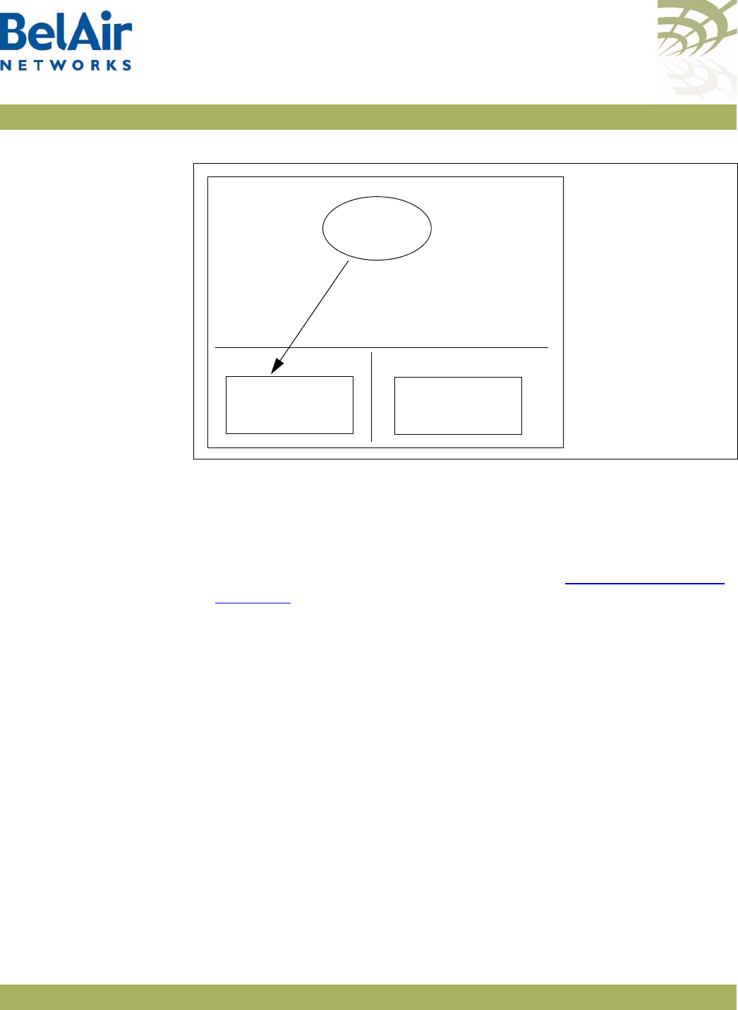
BelAirOS User Guide Performing a Software Upgrade
April 22, 2012 Confidential Page 247 of 362
Document Number BDTM00000-A02 Draft
Figure 17: Active and Standby Software Loads
Under normal operating conditions, the contents of the two software load
banks are identical. During a software upgrade, the new software load is copied
into the standby bank at the time of the upgrade.
A software upgrade consists of the following steps:
1 Ensure the current configuration is saved. Refer to “Saving your Changes”
on page 37.
2 Determine what software load is active (A or B). The new software load will
overwrite the standby bank.
3 Download the new software load. The new software load is downloaded to
the standby software load bank. If A is active, then the new software load is
downloaded to bank B. If B is active, then the new software load is
downloaded to bank A.
4 Verify the new software downloaded successfully.
5 Activate the new software load from the standby software load bank
(containing the new load) by rebooting the AP. The new load is promoted to
active and the formerly active software load bank becomes standby.
6 Verify the configuration and operation of the AP operating with the new
software load
7 Commit the load (copy the newly activated load to the standby software
load bank).
AP
AB
Active
Software Load
Standby
Software Load
Active
Software Load
Pointer to software
load for next restart

BelAirOS User Guide Performing a Software Upgrade
April 22, 2012 Confidential Page 248 of 362
Document Number BDTM00000-A02 Draft
Note: Any configuration changes that you make before you commit the new
software load are lost if you back out of the upgrade.
You can also use BelView NMS to manage how APs are upgraded. For details,
refer to the
BelView NMS User Guide
and “Auto-upgrade” on page 253.
CAUTION! Do not change or save the AP configuration while upgrading the system.
CAUTION! It is always possible to downgrade a committed software load to an older
release. However, while the existing configuration data is saved (upgraded)
during a software upgrade, the existing configuration data could be lost (erased)
during a software downgrade. BelAir Networks recommends that you save and
remotely store the current existing configuration database in case you choose
to downgrade a software load. For instructions on how to downgrade an AP,
contact BelAir Networks.
Displaying the
Active and Next
Software Loads
Display the active software load and the load that is activated at the next
reboot with the following command:
/system/show loads
Downloading a
New Software
Load
/system/upgrade load remoteip <serverIPaddress>
remotepath <serverSubDir>
[{tftp|ftp [user <usrname> password <pword>]}]]
This command downloads a new software image from a remote server. It
copies the new software load into the standby software load bank and sets the
new load as the next active load. See Figure 18 on page 249.
You can use either TFTP or FTP to communicate with the remote server. By
default, the
upgrade load
command uses TFTP. If you specify FTP, you can also
specify the user name and password. The default FTP user name is
anonymous
and the default FTP password is
root@<nodeip>
, where <nodeip> is the IP
address of AP making the request. If you do not use the default FTP username,
the FTP server must be configured to accept your username and password.
CAUTION! Once it begins, the upgrade process cannot be interrupted or terminated by the
user with the current CLI session. See “Canceling a Software Upgrade” on
page 248.
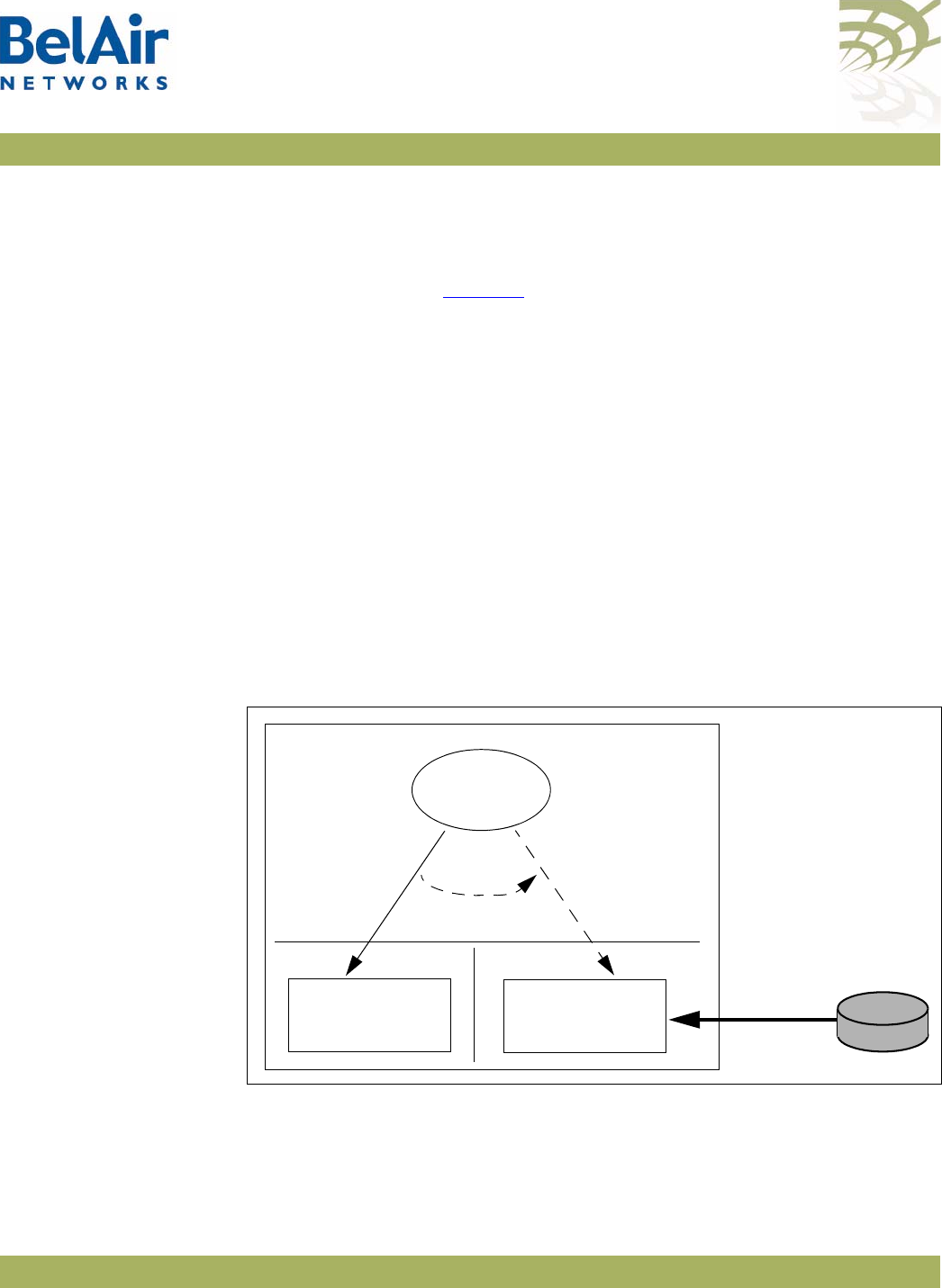
BelAirOS User Guide Performing a Software Upgrade
April 22, 2012 Confidential Page 249 of 362
Document Number BDTM00000-A02 Draft
Canceling a
Software Upgrade
/system/cancel upgrade
This command stops the transfer of the new software load into the standby
software load bank. If you reboot the AP, the software in the active software
load bank is used. See Figure 18.
To cancel the upgrade process:
1 Start another CLI session to the AP being upgraded and log in as in as
root
.
2 Issue the following command:
/system/cancel upgrade
3 When requested, confirm your intent.
If you confirm that you want to cancel the software upgrade, a message
appears in the other CLI session informing it’s user that the upgrade has
been cancelled.
CAUTION! Because the software upgrade process was interrupted, the software in the
standby software load bank may no longer be suitable to reboot the system. Do
not set it to be the next active load unless you first commit the current active
software load, or complete a new software upgrade.
Figure 18: Software Upgrade Step 3 - Downloading the New Software Load
External
TFTP
Server
Software
Download
AP
AB
Active
Software Load
Standby
Software Load
Active
Software Load
Pointer to software
load for next restart

BelAirOS User Guide Performing a Software Upgrade
April 22, 2012 Confidential Page 250 of 362
Document Number BDTM00000-A02 Draft
Verifying a
Successful
Download
Verify that the new software downloaded successfully with the following
command:
/system/show loads verify
The
verify
option calculates and verifies the checksum. A bad checksum
indicates an issue with the load. If there are any issues, perform the download
again.
Example
/system# show loads verify
Application BankA
-----------------
Sw Version: BA100 9.0.0.S.2009.01.05.16.35 (r20884)
State: Running (next reboot)
CommitState: committed
Md5Sum: OK
Application BankB
-----------------
Sw Version: BA100 8.0.8.D.2008.09.18.18.18 (r19148)
State: Shadow
CommitState: committed
Md5Sum: OK
Bootloader Info
---------------
PPC405EP Common Bootloader Version 4.06 11/06/2008
Activating a
Software Load
To activate a software load, enter the following:
/system/reboot
The
reboot
command is only available if you are logged in as
root
.
This command forces the AP to execute with the new load and completes the
activation process.
When upgrading several APs in a network, BelAir Networks recommends that
you reboot the most remote AP first and progress towards the near-end,
AP-by-AP. For star topologies, reboot the subscriber station APs before
rebooting the associated base station AP.
Note: Rebooting an AP as part of a software upgrade can take significantly
longer, up to 20 minutes, depending on the AP’s configuration.
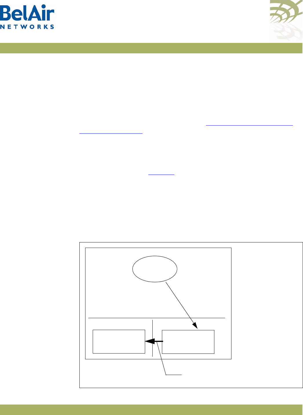
BelAirOS User Guide Performing a Software Upgrade
April 22, 2012 Confidential Page 251 of 362
Document Number BDTM00000-A02 Draft
Verifying the New
Software Load
BelAir Networks recommends that you fully verify the configuration and
operation of an upgraded AP before you commit the new load. Use the
following steps as guidelines.
1 Fully verify the AP’s configuration and operation.
2 If required, adjust any settings and save the new configuration.
3 Reboot the AP and verify that all changes take effect.
If you observe any issues, follow the steps in “Backing Out from a Software
Upgrade” on page 252.
Committing a
New Software
Load
/system/commit load
Once you have activated the AP with new software load, you can commit it
with this command. See Figure 19.
CAUTION! This command copies the contents of the active software bank to the standby
bank. For example, if the active software bank is A, its contents overwrite those
of bank B. Backing out is no longer possible after the new software load has
been committed. After the new software load has been committed, you can no
longer back out of the upgrade; but you can downgrade the AP. For instructions
on how to downgrade an AP, contact BelAir Networks.
Figure 19: Software Upgrade Step 7 - Commit the Software Load
AP
AB
Standby
Software Load
Active
Software Load
Active
Software Load
Pointer to software
load for next restart
Commit: Overwrite old software
load in the standby bank
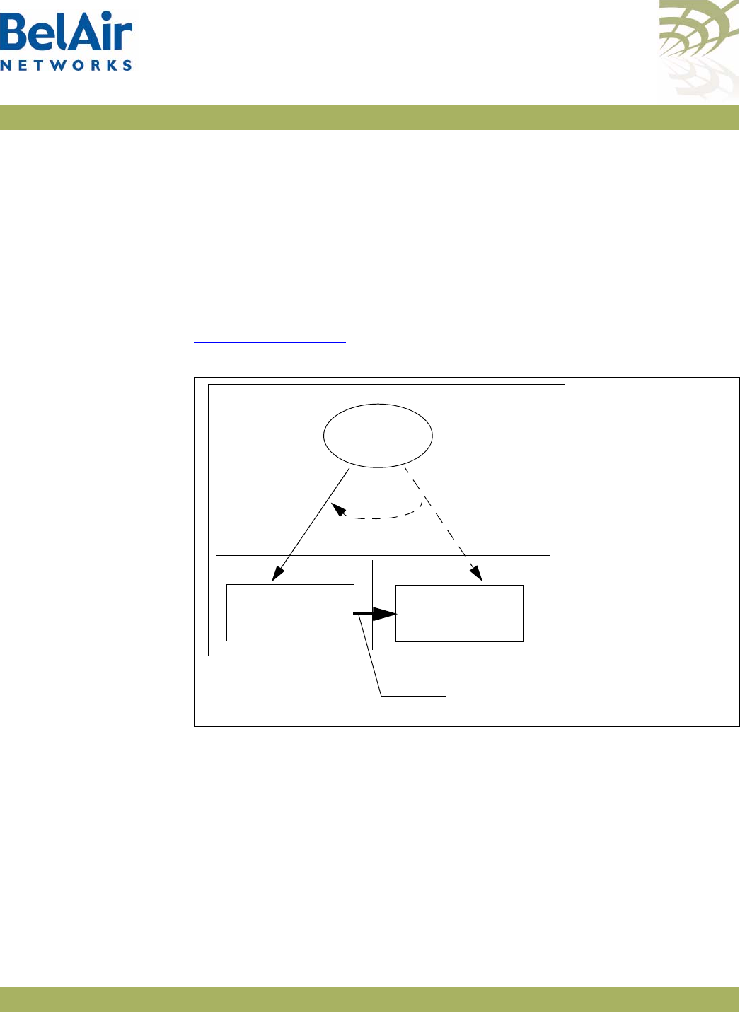
BelAirOS User Guide Performing a Software Upgrade
April 22, 2012 Confidential Page 252 of 362
Document Number BDTM00000-A02 Draft
The
commit
command copies the system software and the configuration
database to the adjacent bank at the time of execution. However, changes to
the active load’s configuration after the
commit
command is executed are not
automatically stored in the standby bank. To keep both banks synchronized, you
must use the
commit
command after every configuration change of the active
load.
Backing Out from
a Software
Upgrade
It is possible to back out from a software upgrade in case its effects are
undesired, but only if the new software load has not been committed. See
Figure 20 on page 252.
Figure 20: Backing Out from an Uncommitted Software Upgrade
When you back out of a software upgrade, the old load overwrites the new
software load.
To back out from an upgrade, do the following steps:
1 Determine which bank has the old software load with the following
command:
/system/show loads
2 Set the old software load to be the next active load with the following
command:
/system/set next-load {A|B}
AP
AB
Old
Software Load
New
Software Load
Active
Software Load
Pointer to software
load for next restart
Activate old
software load
Backout: Overwrite new software
load with old software load

BelAirOS User Guide Performing a Software Upgrade
April 22, 2012 Confidential Page 253 of 362
Document Number BDTM00000-A02 Draft
If you have just upgraded the software, you must set the AP to reboot with
the currently standby load. For example, if the old software load is in
bank A, as shown in Figure 20, and the new software load is in bank B, then
you must activate bank A with the following command:
/system/set next-load A
Alternatively, steps 1 and 2 can be combined with the following command:
/system/set next-load {current|inactive}
If you specify
inactive
, at the next reboot the system uses the bank
containing a load other than the one that is running. Specify
current
to
switch back to the bank containing the active load.
3 Reboot the system, with the
reboot
command.
Note:Rebooting an AP as part of a software upgrade can take significantly
longer, up to 20 minutes, depending on the AP’s configuration.
4 Run the
commit
command.
Running the
commit
command is not necessary if the system is already
executing the old software load (because you have decided, for example, to
back-out of the upgrade before activating the new load). In this case, the
content of the old software load (which is active) overwrites the contents of
the new undesired software load.
Displaying the
Status of the
Software Upgrade
/system/show upgrade status
This command displays the status of the software upgrade process.
Clearing the
Upgrade Failure
Alarm
/system/clear alarm upgrade-failure
This command allows you to clear the alarm generated when a software
upgrade fails.
Auto-upgrade /system/show auto-upgrade
/system/set auto-upgrade {enabled|disabled}
This command allows you to control whether an AP can be upgraded
automatically through BelView NMS. The default setting is
enabled
, meaning
that BelView NMS can automatically upgrade the AP,
For details, refer to the
BelView NMS User Guide.

BelAirOS User Guide Alarm and Event Reporting
April 22, 2012 Confidential Page 254 of 362
Document Number BDTM00000-A02 Draft
Alarm and Event Reporting
The AP alarm and event reporting subsystem monitors both active alarms and
alarm history. Active alarms are stored in system memory and are not
persistent. The AP maintains the history of the last 10 000 reported alarms.
The alarm history is persistent during normal operation.
The alarm and event subsystem allows you to:
• display active alarms, filtered by alarm type and severity level
• display the alarm history, filtered by alarm type and severity level
This chapter contains the following sections:
•“Alarm Types and Severity” on page 254
•“Displaying Active Alarms” on page 255
•“Displaying the Alarm History” on page 255
See also “Alarm and Event Definitions” on page 325.
Alarm Types and
Severity
Table 18 shows the types of alarms that BelAir Networks APs can generate.
APs can produce alarms with the following severity: critical, major, minor,
warning and information.
Table 18: Alarm Types
Type Description
dcom data communication
eqpt equipment (for instance, equipment failures)
sw software (software errors)
qos quality of service
env environment (for instance, temperature too low or
too high)
secu security
sys system

BelAirOS User Guide Alarm and Event Reporting
April 22, 2012 Confidential Page 255 of 362
Document Number BDTM00000-A02 Draft
Displaying Active
Alarms
/system/show alarms <max_num_of_alarms>
[type {all|dcomm|eqpt|sw|qos|env|secu|sys}]
[severity {all|critical|major|minor|warning|info}]
This command allows you to display up to “n” active alarms, filtered by alarm
type or alarm severity. If the alarm severity is to be specified, then the alarm
type must also be specified, but can be specified as
all
if no filtering by type is
desired.
The
type
and
severity
specifications can have multiple values separated by a
vertical bar. For example, specifying
type dcom|eqpt|env
shows all data
communications, equipment and environment alarms.
In the active alarm display:
• The
Id
field indicates the log index number.
• The
Ignored
field indicates whether or not a Syslog and SNMP trap
notification was sent for this item.
Example
In the following example, only one alarm is displayed because only one alarm
was active at the time the command was issued.
/# system/show alarms 20
Displaying 1 active alarms of 1 total:
Id Date/Time (UTC) Severity Status Ignored Entity Type Description
----------------------------------------------------------------------------------------------
0 2004-11-05 19:16:06 critical Set No brm1 dcom Link Down
Displaying the
Alarm History
/system/show alarm history <max_num_of_alarms>
[type {all|dcomm|eqpt|sw|qos|env|secu|sys}]
[severity {all|critical|major|minor|warning|info}]
[<log_idx>]
This command allows you to display up to the last “n” reported alarms, filtered
by alarm type or alarm severity. If the alarm severity is to be specified, then the
alarm type must also be specified, but can be specified as
all
if no filtering by
type is desired.
The
type
and
severity
specifications can have multiple values separated by a
vertical bar. For example, specifying
type dcom|eqpt|env
shows all data
communications, equipment and environment alarms.
The
<log_idx>
parameter specifies the most recent alarm log to display. It
defaults to the last index generated.

BelAirOS User Guide Alarm and Event Reporting
April 22, 2012 Confidential Page 256 of 362
Document Number BDTM00000-A02 Draft
In the alarm history display:
• The
Id
field indicates the log index number.
• The
Ignored
field indicates whether or not a notification (through Syslog or
through SNMP traps) was sent for this item.
The
<max_num_of_alarm>
parameter cannot be greater than 200. To display
alarms that occurred previous to that, note the log index number of the last
displayed alarm and re-issue the
show alarm history
command with the
appropriate
<log_idx>
parameter. See the following examples.
Example 1
The following example displays the five most recent alarms.
/# system/show alarm history 5
Displaying 5 alarm history entries:
Id Date/Time (UTC) Severity Status Ignored Entity Type Description
------------------------------------------------------------------------------------------------
9 2006-01-23 19:40:43 minor Clr No scm eqpt SNTP server not available
8 2006-01-23 19:39:20 critical Clr No brm3 dcom Link Down
7 2006-01-23 19:39:06 critical Set No brm3 dcom Link Down
6 2006-01-23 19:38:00 critical Clr No brm2 dcom Link Down
5 2006-01-23 19:37:45 critical Set No brm2 dcom Link Down
Example 2
The following example displays the next two most recent alarms.
/# system/show alarm history 2 type all severity all 4
Displaying 2 alarm history entries:
Id Date/Time (UTC) Severity Status Ignored Entity Type Description
------------------------------------------------------------------------------------------------
4 2006-01-23 19:36:54 minor Set No scm eqpt SNTP server not available
3 2006-01-23 19:36:29 warning Set No brm3 eqpt Battery missing
Example 3
In the following example, only two alarms are displayed because only two
alarms were active at the time the command was issued.
/# system/show alarm history 20
Displaying 2 alarm history entries:
Id Date/Time (UTC) Severity Status Ignored Entity Type Description
----------------------------------------------------------------------------------------------


BelAirOS User Guide Using Syslog
April 22, 2012 Confidential Page 258 of 362
Document Number BDTM00000-A02 Draft
Using Syslog
In addition to the alarm subsystem, the BelAir Networks APs can generate
other event notifications. With the System Log (Syslog) functions you can:
• send the event notifications to a remote server, including lawful intercept
data
• have them displayed on a CLI session as they occur
• filter the severity of the events that are logged
This chapter contains the following sections
•“Displaying the Syslog Configuration” on page 258
•“Configuring the Syslog Server IP Address” on page 259
•“Sending Syslog Messages to a CLI Session” on page 259
•“Configuring the Log Level” on page 259
•“Configuring the Hostname Option” on page 260
•“Configuring the Keep-alive Interval” on page 260
•“Configuring Lawful Intercept Data Retrieval” on page 260
Displaying the
Syslog
Configuration
/syslog/show config
This command displays the Syslog configuration.
Example
/syslog# show config
System Log Information
----------------------
Log Status : Enable
Lawful-Intercept: Disabled
Monitor Logging : Enable
Log Server IP : 10.1.1.88
Hostname Option : Mac Address
Log Levels : critical
Alive Message : interval 1hr 30min

BelAirOS User Guide Using Syslog
April 22, 2012 Confidential Page 259 of 362
Document Number BDTM00000-A02 Draft
Configuring the
Syslog Server IP
Address
/syslog/logserver {enable [<ip address>] |disable}
This command sets the Syslog server IP address for remote logging. Only one
server can be defined at a time. If a different IP address was configured before,
this command closes the previous connection. Use the
disable
parameter to
remove a Syslog server.
Example
/syslog# logserver enable 10.6.4.52
Sending Syslog
Messages to a CLI
Session
/syslog/monitor logging {enable|disable}
This command instructs the AP to send Syslog messages to the current CLI
session for display as they are generated. If you continue to use the current CLI
session, the Syslog messages are interleaved with regular command input and
output.
This command affects only the current CLI session. A new CLI session does not
have this option enabled. This feature allows the Syslog messages to be
displayed in one CLI session while another CLI session is used for regular
command input and output.
To use this feature, you must first enable a log server with the
logserver {enable
[<ip address>]
command.
Enabling this feature disables the normal CLI session inactivity timer. The CLI
session remains open until this feature is explicitly disabled.
Example
/syslog# monitor logging enable
Configuring the
Log Level
/syslog/loglevel {debug|info|notice|warn|error|
critical|alert|emerg}
This command defines the maximum severity level for messages to be sent to
the remote Syslog server or the CLI session. (See “Configuring the Syslog
Server IP Address” on page 259 and “Sending Syslog Messages to a CLI
Session” on page 259.)
This command restricts logging to messages at the specified level and below (in
the sequence of appearance in the command).
Note: The Syslog message severity levels are separate and distinct from the
alarm severity levels.
The default level is
error
.

BelAirOS User Guide Using Syslog
April 22, 2012 Confidential Page 260 of 362
Document Number BDTM00000-A02 Draft
Example
/syslog# loglevel error
In the preceding example, after the command is issued, the AP generates
error
,
critical
,
alert
and
emerg
messages.
Configuring the
Hostname Option
/syslog/set hostname-type {ip-address|mac-address}
This command lets you send the host name as either an IP address or a MAC
address. The default is to send the host name as an IP address.
Configuring the
Keep-alive
Interval
/syslog/set alive-message {disable |
enable interval [hr <hrs>] [min <mins>]}
This command lets you send a keep-alive message to the remote Syslog server
at a regular interval. The interval should not be shorter than 1 minute.
Configuring
Lawful Intercept
Data Retrieval
/syslog/set lawful-intercept {enable|disable}
This command lets you gather network data pursuant to lawful authority for
the purpose of analysis or evidence. Specifically, when Network Address
Translation (NAT) is enabled, many wireless clients can share a single public IP
address. By enabling lawful intercept data retrieval, the gathered Syslog data
contains the public IP address being used as well as the wireless client IP
address and MAC address. The additional data is delivered in log entries with a
severity level of
warning
.
By default, lawful intercept data retrieval is disabled.
To enable lawful intercept data retrieval:
1 Ensure NAT is enabled. If NAT is disabled, the
/syslog/set lawful-intercept
command is disabled automatically. See “Network Address Translation” on
page 196.
2 Ensure Syslog is enabled:
/syslog# logserver enable 10.1.1.88
3 Enabled lawful intercept data retrieval:
/syslog# set lawful-intercept enable
Lawful Intercept is enabled
4 Ensure the log level is correct:
/syslog# loglevel warn

BelAirOS User Guide Using Syslog
April 22, 2012 Confidential Page 261 of 362
Document Number BDTM00000-A02 Draft
Sample Output
Jan 16 09:46:15 172.16.0.235 Intercept 00:21:6a:78:fb:a4 UDP start 192.168.5.254/1102 <--->
239.255.255.250/1900 rxBytes:0 txBytes:0
Jan 16 09:48:51 172.16.0.235 Intercept 00:21:6a:78:fb:a4 UDP end 192.168.5.254/1102 <--->
239.255.255.250/1900 rxBytes:0 txBytes:322
In the previous sample output:
•
172.16.0.235
is the IP address of the BelAir Networks gateway.
•
00:21:6a:78:fb:a4
is the wireless client’s MAC address.
•
UDP
is the protocol in use. It can also be TCP.
•
192.168.5.254/1002
is the wireless client’s IP address and port.
•
239.255.255.250/1900
is the destination IP address and port.
•
rxBytes
and
txBytes
is the number of Bytes received and sent by the
wireless client.

BelAirOS User Guide Gathering Additional Troubleshooting Information
April 22, 2012 Confidential Page 262 of 362
Document Number BDTM00000-A02 Draft
Gathering Additional Troubleshooting Information
This chapter shows you how to gather and display additional information that
may be useful in resolving potential operational issues.
This chapter contains the following sections:
•“Determining Service Health Levels” on page 262
•“Gathering Hardware Log Files” on page 263
Determining
Service Health
Levels
/interface/wifi-<n>-<m>/set service-health-level-threshold
{noise-floor
|access-tx-error-rate
|access-rx-error-rate
|access-rx-duplicate-frame-rate
|access-low-modulation-rate
|mesh-link-rssi
|mesh-link-tx-error-rate}
|ch-busy-non-local
|ch-busy-noise
|WMOS}
{good-threshold|marginal-threshold}
<threshold value>
/interface/wifi-<n>-<m>/show service-health-level-thresholds
/interface/wifi-<n>-<m>/show service-health-levels
These commands provide equivalent functionality as the BelView NMS RF
Health Audit tool, allowing you to view the current state of RF parameters in
qualitative terms (good, marginal, or bad) instead of quantitative terms.
The
set
command lets you specify the threshold of what would be considered
good or marginal health for each of the RF parameters.
The
show service-health-level-thresholds
command let you display the current
threshold settings. The parameter health is considered:
•
good
if it is above the Good Threshold
•
marginal
if it is above the Marginal Threshold but below the Good Threshold
•
bad
if it is below the Marginal Threshold
Thresholds are measured in dBm for noise floor and RSSI, and % for error and
modulation rates
The
show service-health-level
command let you display the current health levels
of the RF parameters.

BelAirOS User Guide Gathering Additional Troubleshooting Information
April 22, 2012 Confidential Page 263 of 362
Document Number BDTM00000-A02 Draft
Example 1
/interface/wifi-1-2# show service-health-level-thresholds
Threshold Type Good Threshold Marginal Threshold
---------------------------------------------------------------------
Noise Floor -90 -80
Access Tx Error Rate 10 25
Access Rx Error Rate 10 25
Access Rx Duplicate Error Rate 10 25
Access Low Modulation Rate 10 25
Mesh Link RSSI -75 -80
Mesh Link Tx Error Rate 10 25
Example 2
/interface/wifi-1-2# show service-health-levels
Health Level Type Health Level
-----------------------------------------------------------------------
Noise Floor Good
Access Tx Error Rate Good
Access Rx Error Rate Good
Access Rx Duplicate Error Rate Good
Access Low Modulation Rate Good
Mesh Link RSSI:
Link 1: ................... Unknown
Link 2: ................... Unknown
Link 3: ................... Unknown
Link 4: ................... Unknown
Link 5: ................... Unknown
Link 6: ................... Unknown
Link 7: ................... Unknown
Link 8: ................... Unknown
Mesh Link Tx Error Rate:
Link 1: ................... Unknown
Link 2: ................... Unknown
Link 3: ................... Unknown
Link 4: ................... Unknown
Link 5: ................... Unknown
Link 6: ................... Unknown
Link 7: ................... Unknown
Link 8: ................... Unknown
Gathering
Hardware Log
Files
BelAir Networks hardware generates its own operational log files, recording
information in a custom format. This information may be used by your BelAir
Networks representative to identify a potential issue.
TFTP Transfer of
Internal Log Files
/syslog/export logs remoteip <IP_addr>
[flightrecorder]
[logs]
[commands]
[slot <slot_no>]
[filter <string>]
This command instructs the AP to package internal operational and state data
into a flight recorder file, a log file and a commands file, and send them to a
remote file system through TFTP. The resulting files can then be analyzed by

BelAirOS User Guide Gathering Additional Troubleshooting Information
April 22, 2012 Confidential Page 264 of 362
Document Number BDTM00000-A02 Draft
your BelAir Networks representative to identify potential issues. Flight
recorder and log files can be produced for all BelAir Networks cards.
The
flightrecorder
,
logs
and
commands
parameters allows you to specify
whether to send the card’s flight recorder information, log information, or a list
of commands that were executed at that AP.
The
slot
parameter allows you to specify a particular card. Use the
/mode
command to identify the slot number for the card. If unspecified, files are
created and sent for each card in the AP.
The
filter
parameter allows you to restrict the scope of the information
gathered and sent. Only lines containing the specified
<string>
are included in
the files that are sent. The string can specify items such as a date or month. The
specified string is not case sensitive.
The files that are produced and sent through TFTP are named as follows:
<ip><card_type><slot><file_type><date_and_time>.txt (for example,
10.1.1.10htm1Logread2007.12.19.13.27.39.txt)
, where:
• 10.1.1.10 is the IP address of the AP containing the card.
• The card is an HTM located in slot 1.
• The file contains log information, instead of flight recorder information.
• The file was created on December 19, 2007, at 13:27:39.
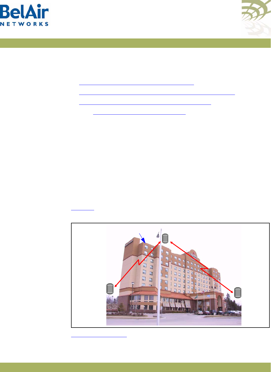
BelAirOS User Guide Troubleshooting Wireless Client Connections
April 22, 2012 Confidential Page 265 of 362
Document Number BDTM00000-A02 Draft
Troubleshooting Wireless Client Connections
This section provides troubleshooting methods for wireless client access issues.
•“Troubleshooting Client Access” on page 265
•“Troubleshooting Client Association and DHCP” on page 267
•“Authentication History Log Messages” on page 268
See also “Wi-Fi Client Statistics” on page 144.
Troubleshooting
Client Access
When a customer reports their wireless client cannot access the Internet, the
corrective steps include the following:
1 Verify the customer’s computer settings for Access Point (AP) connectivity.
2 Reboot a radio (HTM or DRU) with CLI commands.
3 Physically access an AP and power it off and on.
4 Reconfigure an AP. (Requires tier 2 or tier 3 troubleshooting personnel)
5 Replace an AP. (Requires BelAir Networks technical support)
To troubleshoot customer access problems you need to obtain the wireless
client’s physical location and a map with the location of the network APs. See
Figure 21.
Figure 21: Sample Network Map for the Example
Figure 22 on page 266 provides a troubleshooting method, including CLI
commands, to isolate the fault.
AP A
127.16.46.1
AP B
127.16.46.2
AP C
127.16.46.3
Wireless Client
Backhaul
Link
Backhaul
Link
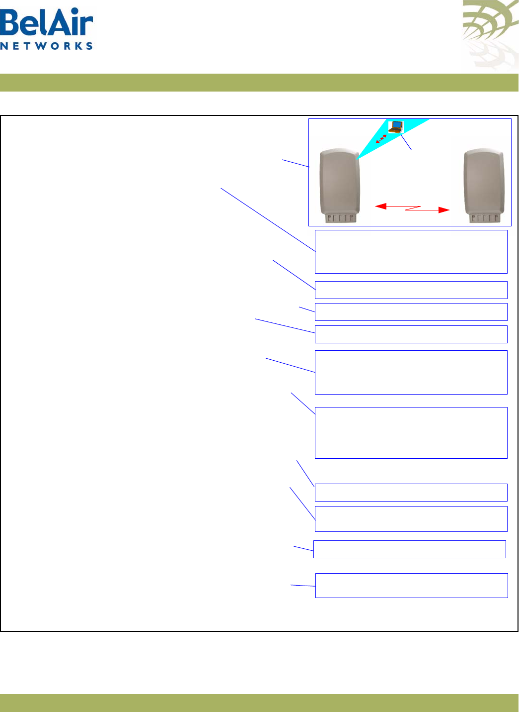
BelAirOS User Guide Troubleshooting Wireless Client Connections
April 22, 2012 Confidential Page 266 of 362
Document Number BDTM00000-A02 Draft
Figure 22: Troubleshooting Wireless Client Access
1 Are there any known outages? If not, go to step 2.
2 Determine the client’s location. Use the network map to
identify the AP associated with the client. For example,
AP A at 172.16.46.1.
3 Use Telnet to access the AP’s radio interface.
a If AP access succeeds, go to step 4.
b If AP access failed, go to step 6.
4 Check the AP’s list of clients.
a If there are clients, the AP is operational.
The problem is with the client, not the network.
b If there are no clients, go to step 5.
5 See if that AP can detect other APs.
a If other APs are active (AGE < 2 seconds), go to step 7.
b If the AP survey fails, reboot the radio card.
Go to step 3.
c If the radio card reboot fails, power the AP off and on.
Go to step 3.
d If the problem persists, replace the AP. Go to step 3.
6 Access a connecting AP and obtain the backhaul link state.
a If the backhaul link state is
up
and the source AP’s
AGE
is < 2 seconds, it is likely a configuration error.
Escalate the problem to tier 2 or 3 troubleshooting
personnel.
b If backhaul link access fails, reboot the backhaul link radio
and check that the link state is up. Go to step 3.
c If the backhaul link radio reboot fails, power the AP off
and on. Go to step 3.
d If the problem persists, replace the AP. Go to step 3.
7 See if a connecting AP’s AP’s can detect other APs.
a If the source AP is present (SSID and MAC address) and
active (AGE < 2 seconds), the AP is functional. The
problem is with the client, not the network.
b If the source AP is not present, power the source AP off
and on. Go to step 3.
c If the problem persists, replace the source AP.
Go to step 3.
> telnet
> open 127.16.46.1
BelAir login: xxxxxxxx
Password: xxxxxxxx
/interface/wifi-<n>-<m>/show clients
/card/<card_type>-<n>/reboot
/interface/wifi-<n>-<m>/show rf-survey
/card/<card_type>-<n>/reboot
> telnet
> open 127.16.46.2
BelAir login: xxxxxxxx
Password: xxxxxxxx
/wifi-<n>-<m>/show backhaul status
/interface/wifi-<n>-<m>/show rf-survey
2.4 GHz
AP A
127.16.46.1
AP B
127.16.46.2
Wireless Client
Backhaul Link
1 Remove the BATT connector
2 Remove the AC connector
3 Reconnect the AC connector
4 Reconnect the BATT connector
1 Remove the AC connector
2 Reconnect the AC connector
1 Remove the AC connector
2 Reconnect the AC connector
5 GHz
DRU
HTM
or
2.4 GHz
5 GHz
DRU
HTM
or

BelAirOS User Guide Troubleshooting Wireless Client Connections
April 22, 2012 Confidential Page 267 of 362
Document Number BDTM00000-A02 Draft
Troubleshooting
Client Association
and DHCP
The AP offers authentication history commands to help you troubleshoot client
association or DHCP issues.
/interface/wifi-<n>-<m>/show authentication history [mac <mac_addr>]
[ssid <ssid_index>]
/interface/wifi-<n>-<m>/set authentication history filter mac
{<client_mac_addr>|all}
/interface/wifi-<n>-<m>/del authentication history
/interface/wifi-<n>-<m>/set authentication history probes
{enable|disable}
These commands allow you to display authentication and DHCP log
information.
The displayed information includes:
• a log index number
• the client’s MAC address
• the date and time the event occurred
• log messages as described in “Authentication History Log Messages” on
page 268.
You can use the following to control or focus the information being displayed:
• Specifying a filter in the
set
command restricts the recording of log messages
to a specific MAC address. The default filter is FF:FF:FF:FF:FF:FF, meaning
that filtering is disabled.
• Enabling probes allows probe information to the displayed. By default, probe
information is not shown.
• Specifying a particular MAC address or SSID index in the
show
command
restricts the display to the log events for the client with that MAC address
or SSID index.
Use the
del
parameter to clear the recorded log information from the AP.
Example
/interface/wifi-1-1# show authentication history mac 00:05:4E:4F:39:D8
Client Authentication History - [filter: FF:FF:FF:FF:FF:FF] [probes: disabled]
--------------------------------------------------------------------
002 [00:05:4E:4F:39:D8] 2006-09-28 02:52:59 DHCP [192.168.219.1]->[192.168.219.1] - [request]->[ack]
003 [00:05:4E:4F:39:D8] 2006-09-28 02:52:59 DHCP [192.168.219.1]->[192.168.219.1] - [offer]->[request]
004 [00:05:4E:4F:39:D8] 2006-09-28 02:52:59 DHCP [0.0.0.0]->[192.168.219.1] - [discover]->[offer]
005 [00:05:4E:4F:39:D8] 2006-09-28 02:52:59 DHCP [0.0.0.0]->[0.0.0.0] - [init]->[discover]
006 [00:05:4E:4F:39:D8] 2006-09-28 02:52:59 <g> WPA authentication complete
007 [00:05:4E:4F:39:D8] 2006-09-28 02:52:55 <r> EAP Replay counter mismatch
008 [00:05:4E:4F:39:D8] 2006-09-28 02:52:53 <r> Client failing to reply to EAP packet...retrying.
009 [00:05:4E:4F:39:D8] 2006-09-28 02:52:50 WPA assoc Complete

BelAirOS User Guide Troubleshooting Wireless Client Connections
April 22, 2012 Confidential Page 268 of 362
Document Number BDTM00000-A02 Draft
-------------------------------end----------------------------------
Authentication
History Log
Messages
The following success or failure codes precede the displayed log messages:
•
<r>
, (red), indicating a failure
•
<g>
, (green), indicating a successful or complete association or
authentication
•
<b>
, (blue), indicating a significant non-failure event, such as the beginning of
authentication
Information events do not display a preceding success or failure code.
The following sections describe the different types of events that the log
messages describe:
•“Normal Network Events” on page 268
•“Normal Client Events” on page 269
•“Network Failure Events” on page 270
•“Client Failure Events” on page 270
•“Client EAP Failure Events” on page 271
Each section lists the actual displayed log message followed by a brief
explanation.
Normal Network
Events RADIUS server accepted client
This log message is generated when the RADIUS server sends the
access-accept
packet.
DHCP [previous state]->[new state] – [previous IP]->[new IP]
The DHCP exchange between the client and the DHCP server generate several
log messages with this format. Refer to Table 19 for a description of the various
states.
Previous IP
and
new IP
are extracted from the captured packets.
Table 19: DHCP State Descriptions
DHCP State Description
Init Initialized state
Discover The client sent a DHCP
discover
packet.

BelAirOS User Guide Troubleshooting Wireless Client Connections
April 22, 2012 Confidential Page 269 of 362
Document Number BDTM00000-A02 Draft
Normal Client Events <b> Starting authentication (open/shared key)
The client has sent an authentication packet to start the authentication process.
The log indicates whether the authentication was
open
or
shared key
.
<?> “ENCRYPTION_TYPE” association complete
The client has completed its association. The encryption type is one of
open
,
wep
,
dot1x
,
wpa
,
wpapsk
,
wpa2
or
wpa2psk
.
The following success or failure codes apply to this log:
•
<g>
when the encryption type is
open
or
wep
• none for all other encryption types
For
open
and
wep
, the log message indicates the client is authorized to carry
packets.
For all other encryption types, the log message indicates that clients are now
EAP-authorized (that is, able to send EAP packets) and EAP processing begins.
Offer The server sent a DHCP
offer
packet to the client.
Request The client sent a DHCP
request
packet
.
Decline The server declined the requested IP from the client.
Ack The server acknowledges the IP requested by the client.
Nack The server sends a negative acknowledgement for the IP
requested by the client.
Release The server releases the client of its IP.
Inform The client sends a DHCP
inform
packet.
Arp_response An ARP response packet from the client was captured. The
IP in this packet is the client’s IP.
Static A static IP was detected.
Table 19: DHCP State Descriptions (Continued)
DHCP State Description

BelAirOS User Guide Troubleshooting Wireless Client Connections
April 22, 2012 Confidential Page 270 of 362
Document Number BDTM00000-A02 Draft
<g> “ENCRYPTION_TYPE” authentication complete
EAP processing has completed successfully. The encryption type is one of
dot1x
,
wpa
,
wpapsk
,
wpa2
or
wpa2psk
.
<r> Disassociation packet received
The client has sent a disassociation or deauthentication packet to invoke a
disconnection from the BelAir Networks authenticator.
Received EAP identity: %s
The authenticator has captured the client’s EAP identity during EAP
authentication.
Network Failure Events <r> Cannot reach RADIUS server
For
dot1x
,
wpa1
or
wpa2
encryption, the authenticator must contact a
configured RADIUS server.
<r> RADIUS server rejected client - please refer to Radius Server logs for
reason
The RADIUS server has sent an
access-reject
packet. If the client is not
authorized or is not configured properly for the RADIUS server that it is
currently trying to connect to, the RADIUS server sends a failure message to
the client.
Depending on the RADIUS configuration, this failure can be for any number of
reasons. Refer to the RADIUS server logs for the specific failure reason.
Client Failure Events <r> Client has wrong WPA PSK key configured
This applies only to WPA1 and WPA2.
<r> Wrong WEP key configured
<r> encryption problems on client
These log messages occur after five continuous decrypting failures on packets
sent by the client.
The
Wrong WEP key configured
log message is displayed if the client uses
wep
encryption and
open
authentication to carry traffic. The other log message is
displayed for all other encryption types.

BelAirOS User Guide Troubleshooting Wireless Client Connections
April 22, 2012 Confidential Page 271 of 362
Document Number BDTM00000-A02 Draft
<r> denied by ACL
The client MAC address is not in the ACL.
<r> does not have proper WPA or RSN IE's in assoc req
<r> WPA IE does not match the advertised WPA IE
<r> RSN IE does not match the advertised RSN IE
The information element in the association packet does not match the
configured AP information element. For example, this can happen when the AP
is configured for WPA2 and the client has selected WPA or when the client has
WPA with AES selected when the SSID is configured for WPA with TKIP.
Note: Not all clients reproduce this error. Some clients do not try to
associate to an AP if their configured information element is different
than the APs.
Client EAP Failure
Events <r> Client timed out while trying to connect with the RADIUS server
The client has failed to respond to the RADIUS server packets within a
30 second interval.
<r> EAP packet from client, but not EAP-enabled SSID[%d]
The SSID is not configured for EAP but the client is sending EAP packets.
<r> Client failing to reply to EAP packet...retrying
The EAP packet, used for
dot1x
,
wpa1, wpa1psk, wpa2
and
wpa2psk
, did not
reach the client or the client did not properly decrypt the packet. The
authenticator retries the EAP exchange three times, then times out and
restarts the entire authentication process.
<r> timed out WPA1 EAP exchange
<r> timed out WPA2 EAP exchange
The client has failed to respond to the EAP packet after three retries and the
EAP process restarts.
<r> EAP replay counter mismatch
The EAP replay counter does not match the number of key packets sent.
The EAP key contains a replay counter that increments with each EAP key
packet to protect against issues with key exchange. If the counter does not
match the number of key packets sent, the client restarts the EAP
authentication.

BelAirOS User Guide Troubleshooting Wireless Client Connections
April 22, 2012 Confidential Page 272 of 362
Document Number BDTM00000-A02 Draft
This applies only to WPA1 and WPA2.
<r> Received msg didn't contain same IE as in assoc req
The EAP key contains an information element that should match the
information element in the association request packet.
This applies only to WPA1 and WPA2.
<r> EAP key descriptor doesn't match
The EAP packet contains information about what encryption type to use. The
client must supply the information so that it matches the AP encryption type.
This applies only to WPA1 and WPA2.
<r> MIC failure %d in %d seconds on ssid %d
The BelAir Networks authenticator considers this event as an attack. The
offending client is deauthenticated and no associations are allowed for two
minutes.

BelAirOS User Guide Running Link Diagnostics
April 22, 2012 Confidential Page 273 of 362
Document Number BDTM00000-A02 Draft
Running Link Diagnostics
This chapter describes tools to help you determine the relative health of your
links.
This chapter contains the following sections:
•“Path Trace Tool” on page 273
•“Traffic Tool” on page 273
Path Trace Tool /diagnostics/trace path <ip_address>
This command displays the number of hops between you and the supplied IP
address.
The
trace path
command only operates on BelAir Networks APs. If there is a
non-BelAir Networks AP in between source AP and the destination AP, the
trace result displays
unreachable
.
Example
/diagnostics# trace path 10.9.9.110
PING 10.9.9.110 (10.9.9.110): 56 data bytes
64 bytes from 10.9.9.110: icmp_seq=0 ttl=64 time=37.7 ms
64 bytes from 10.9.9.110: icmp_seq=1 ttl=64 time=17.1 ms
64 bytes from 10.9.9.110: icmp_seq=2 ttl=64 time=11.3 ms
--- 10.9.9.110 ping statistics ---
3 packets transmitted, 3 packets received, 0% packet loss
round-trip min/avg/max = 11.3/22.0/37.7 ms
hop 1: IP 10.9.9.201
hop 2: IP 10.9.9.200
hop 3: IP 10.9.9.51
hop 4: IP 10.9.9.110
Tra ffic To ol /diagnostics/test link IP <ip_addr> rate-kbps <num_str>
{ hop-by-hop | end-to-end }
[update_interval <num_str>]
[duration <num_str>]
[dir {rx|tx|both}]
[ip_scope <ip_addr>]
/diagnostics/stop {all | session <session_id> ip_scope <ip_addr>}
/diagnostics/show status
This command first runs a path trace and then runs traffic between you and a
supplied IP address.

BelAirOS User Guide Running Link Diagnostics
April 22, 2012 Confidential Page 274 of 362
Document Number BDTM00000-A02 Draft
To perform multiple simultaneous link tests, each to a different destination IP
address, use multiple CLI sessions with each session running its own link test.
The
rate-kbps
parameter specifies amount of traffic to be run, in kbps.
The
hop-by-hop
and
end-to-end
parameter specify the type of test result
information that is displayed:
• The
hop-by-hop
option displays test results in multiple columns, with each
column displaying the test results for each hop taken to reach the
destination IP address. For example, if the destination IP address is
separated from the BelAir Networks AP by an intermediate AP, then two
columns of test results are displayed. One column has the test results for
the hop from the BelAir Networks AP to the intermediate AP. The second
column has the test results for the hop from the intermediate AP to the
destination IP address.
• The
end-to-end
option displays as single column of test results showing the
traffic rate from the BelAir Networks AP to the destination IP address.
The
update_interval
parameter specifies in seconds the interval that the result
is sampled. It ranges from 1 to 5. The default value is 1 second. The
duration
parameter must be a multiple of the
update_interval
parameter.
The
duration
parameter specifies how long to run traffic in seconds. It ranges
from 10 to 30 and must be larger than the
update_interval
parameter. The
default value is 10 seconds.
If
update_interval
is 2 seconds, and
duration
is 10 seconds, 5 sample results are
displayed every 2 seconds.
The
dir
parameter specifies the traffic direction. The default value is
rx
.
The
ip_scope
parameter is used when an intermediate AP in the path to the
destination IP address is busy running a previous specified link test. Normally
specifying a second link test through the same intermediate AP would fail.
However, by specifying a non-default IP scope, you can proceed with the second
link test. The
ip_scope
parameter accepts values of the following format:
xxx.yyy.zzz.255. You can use any valid IP range except 192.168.1.255,
192.168.2.255 and 192.168.3.255. These three ranges are reserved for internal
use by BelAir Networks APs.
Use the
stop test
command to stop one or all running tests. Use the s
how
status
command to display the test that are currently running and their session

BelAirOS User Guide Running Link Diagnostics
April 22, 2012 Confidential Page 275 of 362
Document Number BDTM00000-A02 Draft
ID. The
session_id
parameter identifies each session, The
session_id
parameter
ranges from 1 to the maximum number of radios in the AP.
Example 1 - Hop-by-hop
diagnostics# test link IP 10.1.1.201 rate 1 hop-by-hop
Trace path:
PING 10.1.1.201 (10.1.1.201): 56 data bytes
64 bytes from 10.1.1.201: icmp_seq=0 ttl=64 time=22.3 ms
64 bytes from 10.1.1.201: icmp_seq=1 ttl=64 time=31.7 ms
64 bytes from 10.1.1.201: icmp_seq=2 ttl=64 time=36.6 ms
--- 10.1.1.201 ping statistics ---
3 packets transmitted, 3 packets received, 0% packet loss
round-trip min/avg/max = 22.3/30.2/36.6 ms
hop 1: IP 10.1.1.202
hop 2: IP 10.1.1.201
Test Hop By Hop. scope 192.168.3.0
Test link between 10.1.1.100 and 10.1.1.201, for 10 sec at 1
mbps, update interval 1 sec using unidirectional TCP test: RX.
(Default output in Kbit/s).
Link test started:
Time hop1 hop2
Sec Rx/Tx Rx/Tx
Kbit/s Kbit/s
1 866/0K 808/0K
2 864/0K 831/0K
3 949/0K 631/0K
4 966/0K 452/0K
5 976/0K 432/0K
6 986/0K 336/0K
7 987/0K 335/0K
8 988/0K 324/0K
9 992/0K *
10 989/0K 299/0K
Example 2 - End-to-end
/diagnostics# test link 1 IP 10.1.1.201 rate 1 end-to-end
Trace path:
PING 10.1.1.201 (10.1.1.201): 56 data bytes
64 bytes from 10.1.1.201: icmp_seq=0 ttl=64 time=14.5 ms
64 bytes from 10.1.1.201: icmp_seq=1 ttl=64 time=42.2 ms
64 bytes from 10.1.1.201: icmp_seq=2 ttl=64 time=59.9 ms
--- 10.1.1.201 ping statistics ---
3 packets transmitted, 3 packets received, 0% packet loss
round-trip min/avg/max = 14.5/38.8/59.9 ms
hop 1: IP 10.1.1.202

BelAirOS User Guide Running Link Diagnostics
April 22, 2012 Confidential Page 276 of 362
Document Number BDTM00000-A02 Draft
hop 2: IP 10.1.1.201
Test Enb By End. scope 192.168.3.0
Test link between 10.1.1.100 and 10.1.1.201, for 10 sec at 1
mbps, update interval 1 sec using unidirectional TCP test: RX.
(Default output in Kbit/s).
Link test started:
Time
Sec Rx/Tx
Kbit/s
1 858/0K
2 924/0K
3 946/0K
4 971/0K
5 976/0K
6 987/0K
7 988/0K
8 988/0K
9 992/0K
10 989/0K
Example 3
/diagnostics# show status
Traffic test status on this node:
session 2 on IP scope 192.168.3.0
session 1 on IP scope 192.168.3.0

BelAirOS User Guide Web Radio Troubleshooting Tools
April 22, 2012 Confidential Page 277 of 362
Document Number BDTM00000-A02 Draft
Web Radio Troubleshooting Tools
The Web interface provides the following tools to display radio performance
metrics:
• a throughput meter
• histogram display of various performance metrics
These tools allow you to:
• monitor your network in greater detail
• identify APs that are approaching their maximum capacity so network
improvements can be made
• identify clients that are heavy users
• identify channels that are approaching their maximum capacity, so that
network changes can be made to improve system performance.
Tool Access Access the Web interface as described in “Web Interface” on page 24.
Each tool has its own web page under each radio physical interface. See
Figure 23 on page 278.
Throughput
Meter
This tool provides throughput statistics on the following entities in an AP:
•the entire AP
• individual SSIDs
• clients, identified by their MAC address and sorted under their appropriate
SSID
• multipoint-to-multipoint mesh links
The following statistics are captured and displayed for each entity:
• throughput in kb/sec and packets/sec
• percentage of bandwidth used:
—SSID bandwidth, as a percentage of the bandwidth of the entire AP
—client bandwidth, as a percentage of the SSID bandwidth
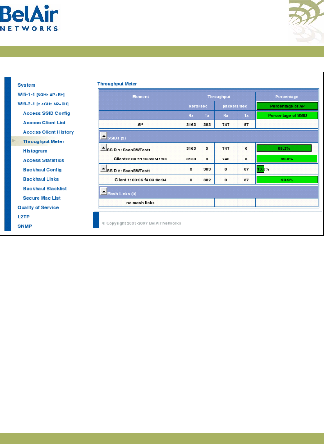
BelAirOS User Guide Web Radio Troubleshooting Tools
April 22, 2012 Confidential Page 278 of 362
Document Number BDTM00000-A02 Draft
Figure 23: Throughput Meter Sample Output
Histogram This tool collects data from the radio and records it in a histogram table. See
Figure 24 on page 279.
Histogram Modes A histogram can be displayed for the following types of data, as specified by the
Mode
list:
• Valid Packet Rx Host (rh) - displays a distribution of all valid incoming
packets destined for the local AP.
Zoom and Shift
Functions Histogram bins can be shifted and zoomed for more or less precision. See
Figure 24 on page 279.
• zoom - changes the displayed bin width, giving you more or less information
what makes up a particular bin. For example, if 80% of the traffic is displayed
in a bin representing -75 to -80 dBm, then successively clicking on the
zoom
in
button changes the definition of each bin to be -2 dBm wide instead of -5
dBm. Thus, the 80% of traffic is displayed among more bins giving you more
information about the traffic distribution.
• shift - displays more bins from one direction while hiding bins from the
other
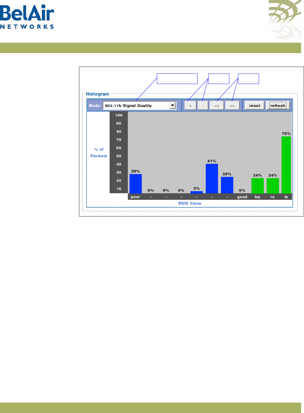
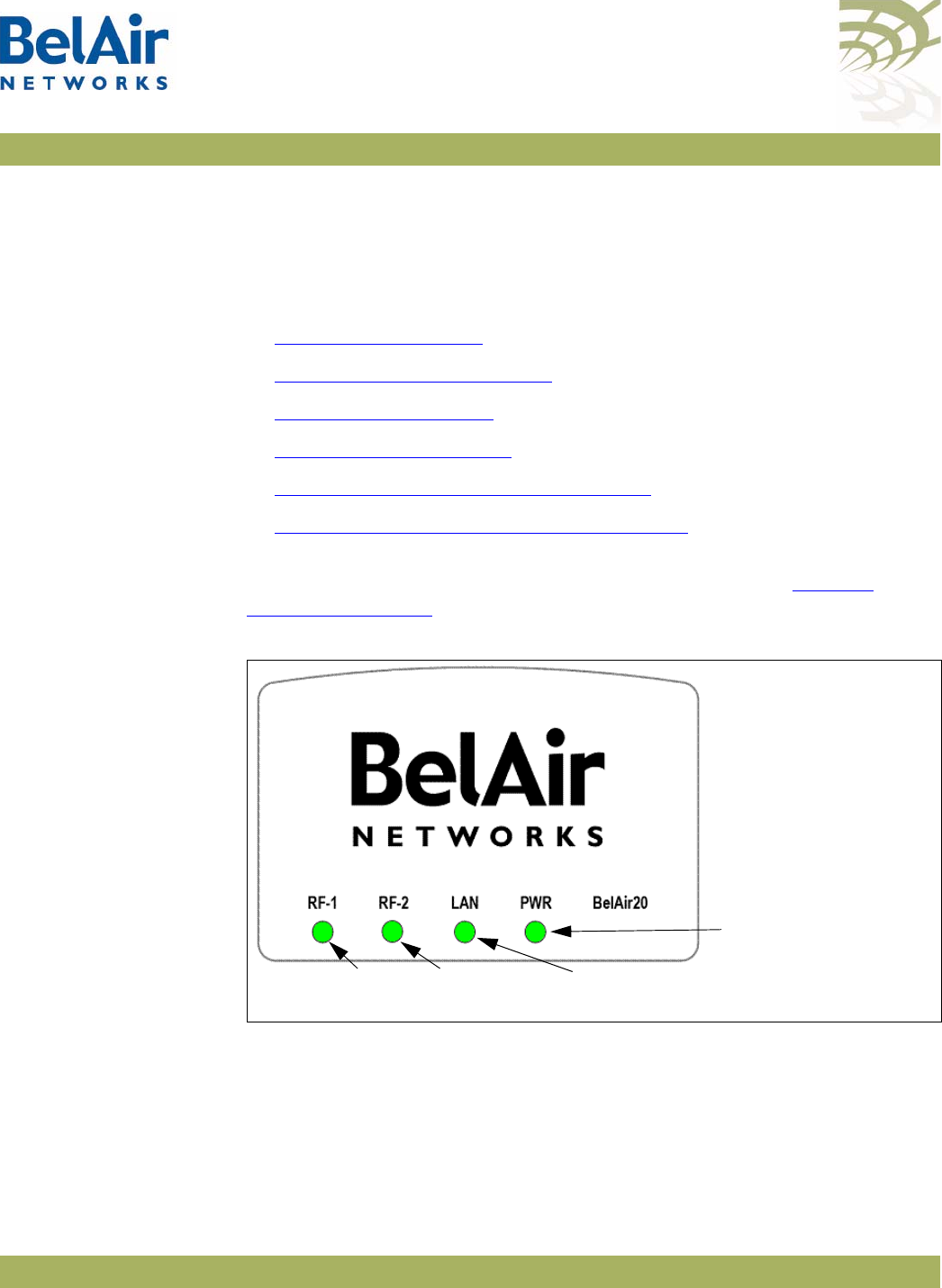
BelAirOS User Guide AP LED Descriptions
April 22, 2012 Confidential Page 280 of 362
Document Number BDTM00000-A02 Draft
AP LED Descriptions
This chapter contains the following sections describing the LEDs available for
each AP:
•“BelAir20” on page 280
•“BelAir100i WCS” on page 282
•“BelAir20E” on page 283
•“BelAir20EO” on page 285
•“BelAir100N and BelAir2100” on page 286
•“BelAir100SN and BelAir100SNE” on page 288
BelAir20 The BelAir20 includes four status LED indicators described in Figure 25 and
Table 20 on page 281.
Figure 25: LEDs
802.11 a/n
Indicator 802.11 b/g/n
Indicator
Ethernet Link/
Activity
Power

BelAirOS User Guide AP LED Descriptions
April 22, 2012 Confidential Page 281 of 362
Document Number BDTM00000-A02 Draft
Table 20: LED Behavior
LED Status Description
RF-1
(802.11 a/n 5.8 GHz)
Off
Flashing Green
Green
Flashing Blue
Blue
No power to unit or unit cannot boot.
802.11 a/n is disabled.
802.11 a/n is enabled, backhaul is disabled.
802.11 a/n is enabled, some backhaul links are down.
802.11 a/n is enabled, all backhaul links are up.
RF-2
(802.11 b/g/n 2.4 GHz)
Off
Flashing Green
Green
Flashing Blue
Blue
No power to unit or unit cannot boot.
802.11 b/g/n is disabled.
802.11 b/g/n is enabled, backhaul is disabled.
802.11 b/g/n is enabled, some backhaul links are down.
802.11 b/g/n is enabled, all backhaul links are up.
LAN Off
Blue
Green
Orange
Flashing
There is no connection on the LAN port.
Indicates a 1000 Mbps link.
Indicates a 100 Mbps link.
Indicates a 10 Mbps link.
Indicates activity.
PWR Off
Flashing Red
Red
Flashing Amber
Amber
Flashing Green
Green
Indicates that there is no power to the unit.
Indicates that a hardware fault has been detected.
Indicates that there is a software error, system cannot boot.
Indicates that the reset button has been pushed. (RF-1 and
RF-2 are flashing cyan.)
Indicates that the system is booting. (RF-1 and RF-2 are
initially cyan, then turn off as the unit completes the boot
process.)
Indicates that configuration data is being downloaded or that
unit is searching for a configuration server
Indicates that the unit is up and running.
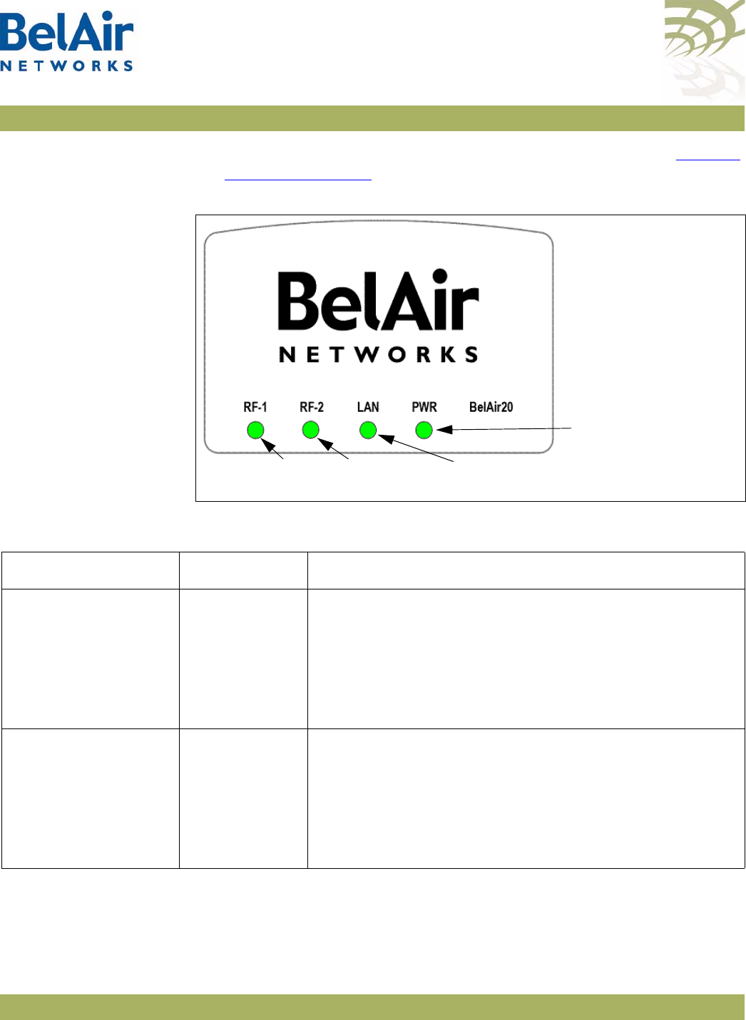
BelAirOS User Guide AP LED Descriptions
April 22, 2012 Confidential Page 282 of 362
Document Number BDTM00000-A02 Draft
BelAir100i WCS The BelAir100i WCS includes four status LED indicators described in Figure 25
and Table 20 on page 281.
Figure 26: LEDs
802.11 n
Indicator
802.11 b/g/n
Indicator
Ethernet Link/
Activity
Power
Table 21: LED Behavior
LED Status Description
RF-1
(802.11 n 2.3 GHz)
Off
Flashing Green
Green
Flashing Blue
Blue
No power to unit or unit cannot boot.
802.11 n is disabled.
802.11 n is enabled, backhaul is disabled.
802.11 n is enabled, some backhaul links are down.
802.11 n is enabled, all backhaul links are up.
RF-2
(802.11 b/g/n 2.4 GHz)
Off
Flashing Green
Green
Flashing Blue
Blue
No power to unit or unit cannot boot.
802.11 b/g/n is disabled.
802.11 b/g/n is enabled, backhaul is disabled.
802.11 b/g/n is enabled, some backhaul links are down.
802.11 b/g/n is enabled, all backhaul links are up.

BelAirOS User Guide AP LED Descriptions
April 22, 2012 Confidential Page 283 of 362
Document Number BDTM00000-A02 Draft
BelAir20E The BelAir20E includes four status LED indicators described in Figure 25 and
Table 20 on page 281.
LAN Off
Blue
Green
Orange
Flashing
There is no connection on the LAN port.
Indicates a 1000 Mbps link.
Indicates a 100 Mbps link.
Indicates a 10 Mbps link.
Indicates activity.
PWR Off
Flashing Red
Red
Flashing Amber
Amber
Flashing Green
Green
Indicates that there is no power to the unit.
Indicates that a hardware fault has been detected.
Indicates that there is a software error, system cannot boot.
Indicates that the reset button has been pushed. (RF-1 and
RF-2 are flashing cyan.)
Indicates that the system is booting. (RF-1 and RF-2 are
initially cyan, then turn off as the unit completes the boot
process.)
Indicates that configuration data is being downloaded or that
unit is searching for a configuration server
Indicates that the unit is up and running.
Table 21: LED Behavior (Continued)
LED Status Description

BelAirOS User Guide AP LED Descriptions
April 22, 2012 Confidential Page 284 of 362
Document Number BDTM00000-A02 Draft
Figure 27: LEDs
POWER INTERNET2.4G 5G
802.11 a/n
Indicator
802.11 b/g/n
Indicator
Ethernet Link/
Activity
Power
Table 22: LED Behavior
LED Status Description
POWER Off
Red
Flashing Blue
Blue
No power to the AP.
Hardware fault, software error, or system cannot boot.
Configuration data is being downloaded or that AP is
searching for a configuration server
AP is up and running.
2.4G
(802.11 b/g/n 2.4 GHz)
Off
Flashing Blue
Blue
No power to AP or AP cannot boot.
Interface is disabled, or 802.11 b/g/n is enabled and some
backhaul links are down.
Backhaul is disabled, or 802.11 b/g/n is enabled and all
backhaul links are up.
5G
(802.11 a/n 5 GHz)
Off
Flashing Blue
Blue
No power to AP or AP cannot boot.
Interface is disabled, or 802.11 a/n is enabled, some backhaul
links are down.
Backhaul is disabled, or 802.11 a/n is enabled, all backhaul
links are up.
INTERNET Off
Flashing Blue or
Steady Blue
No power to AP or AP cannot boot.
WAN port has Ethernet connectivity.
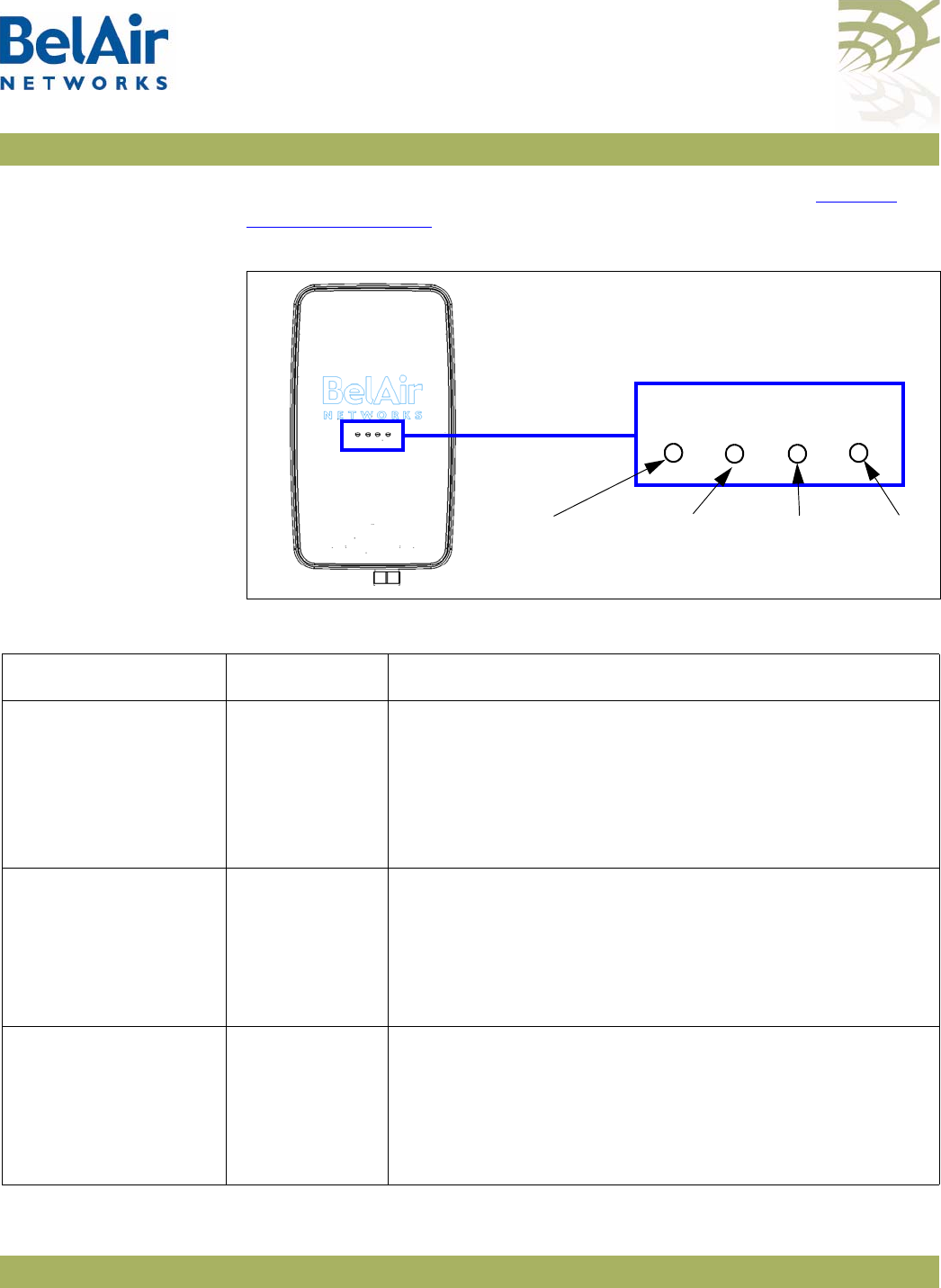
BelAirOS User Guide AP LED Descriptions
April 22, 2012 Confidential Page 285 of 362
Document Number BDTM00000-A02 Draft
BelAir20EO The BelAir20EO includes four status LED indicators described in Figure 25 and
Table 20 on page 281.
Figure 28: LEDs
2.4G
INTERNET POWER
5G
802.11 a/n
Indicator
802.11 b/g/n
Indicator
Ethernet Link/
Activity
Power
Table 23: LED Behavior
LED Status Description
POWER Off
Red
Flashing Blue
Blue
No power to the AP.
Hardware fault, software error, or system cannot boot.
Configuration data is being downloaded or that AP is
searching for a configuration server
AP is up and running.
2.4G
(802.11 b/g/n 2.4 GHz)
Off
Flashing Blue
Blue
No power to AP or AP cannot boot.
Interface is disabled, or 802.11 b/g/n is enabled and some
backhaul links are down.
Backhaul is disabled, or 802.11 b/g/n is enabled and all
backhaul links are up.
5G
(802.11 a/n 5 GHz)
Off
Flashing Blue
Blue
No power to AP or AP cannot boot.
Interface is disabled, or 802.11 a/n is enabled, some backhaul
links are down.
Backhaul is disabled, or 802.11 a/n is enabled, all backhaul
links are up.
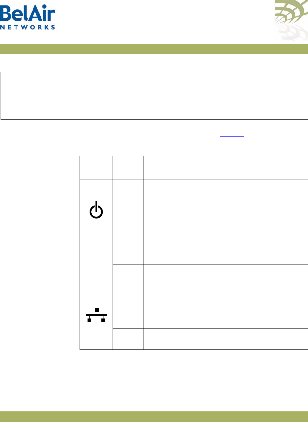
BelAirOS User Guide AP LED Descriptions
April 22, 2012 Confidential Page 286 of 362
Document Number BDTM00000-A02 Draft
BelAir100N and
BelAir2100
The unit has three external LEDs as described inTable 24.
INTERNET Off
Flashing Blue or
Steady Blue
No power to AP or AP cannot boot.
WAN port has Ethernet connectivity.
Table 23: LED Behavior (Continued)
LED Status Description
Table 24: LED Behavior - BelAir100N, BelAir100NE or BelAir2100
LED
Name
LED
State Unit State Description
Power Off Off No power to the unit. Check power
cable connection and power source.
Amber Initialization The unit is initializing.
Flashing
Green
Autoconfiguring The unit is downloading
autoconfiguration data.
Green Operational Self-test passed and
autoconfiguration completed (if
applicable)
Red Not
operational
Self-test failed.
Restart the unit.
Ethernet Off No cable A cable is not connected between
the Ethernet port and the far-end.
Green Cable is
connected
A cable is connected between the
Ethernet port and an active far-end.
Flashing
Green
Operational Data is being transferred across the
link.
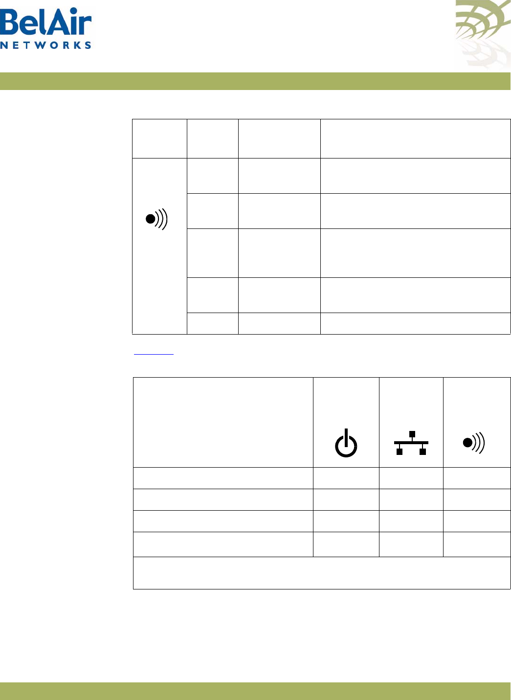
BelAirOS User Guide AP LED Descriptions
April 22, 2012 Confidential Page 287 of 362
Document Number BDTM00000-A02 Draft
BelAir100N and
BelAir2100 Power-up
LED Sequence
Table 25 shows the normal power-up LED sequence.
Radio or
Mesh
Off Hardware
failure
Hardware failure, no power to the
unit or radio initialization
Amber Not
operational
All of the P-to-P and P-to-MP links
are down.
Flashing
Amber
P-to-P and/or
P-to-MP link
failure
One or more, but not all, of the
P-to-P and/or P-to-MP links are
down.
Flashing
Green
MP-to-MP link
failure
One or more of the MP-to-MP links
are down.
Green Operational All links are operational.
Table 24: LED Behavior - BelAir100N, BelAir100NE or BelAir2100
LED
Name
LED
State Unit State Description
Table 25: Normal Power-Up LED Sequence
Power-up Sequence
Power Ethernet Radio/Mesh
Off Off Off Off
On Amber Off Off
After 1 minute Green Off Amber
After 2 minutes Green Off1Green
Note: Light is either off or flashing green if data is transferred across the
Ethernet link.
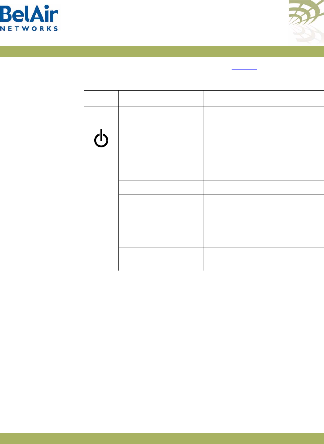
BelAirOS User Guide AP LED Descriptions
April 22, 2012 Confidential Page 288 of 362
Document Number BDTM00000-A02 Draft
BelAir100SN and
BelAir100SNE
The unit has three external LEDs as described inTable 26.
Table 26: LED Behavior - BelAir100SNE and BelAir100SNE
LED Colour State Description
Power Off Off No power to the unit. Check power
cable connection and power source.
If the voltage is low, 45 VAC or less,
check the cable connection between
the AP and the power tap. You may
need to use a solid 0.5-inch cable
rather than a lossy 75-ohm cable.
Amber Initialization The unit is initializing.
Flashing
Green
Autoconfiguring The unit is downloading
autoconfiguration data.
Green Operational Self-test passed and
autoconfiguration completed (if
applicable)
Red Not
operational
Self-test failed.
Restart the unit.

BelAirOS User Guide AP LED Descriptions
April 22, 2012 Confidential Page 289 of 362
Document Number BDTM00000-A02 Draft
Cable
Modem
or
Ethernet
Off Not
operational
Cable Modem link is down.
Flashing
Blue
Initialization Synchronizing with the Cable Modem
Termination System (CMTS). May
take up to 5 minutes.
After 5 minutes, this state indicates
that the RF signal strength is out of
range, the MAC address may not be
recorded at the CMTS or an IP
address may not be assigned to the
unit.
Note the unit’s MAC address located
at the bottom of the unit and call the
Network Operating Centre to
confirm MAC address registration
and IP address assignment.
After verifying the IP address, check
L2TP tunneling configuration.
Blue Operational Cable Modem is operational
Green Not
operational
Cable Modem link is down. A cable is
connected between the Ethernet
port and an active far-end.
Flashing
Green
Not
operational
Cable Modem link is down. Data is
being transferred across the Ethernet
link.
Table 26: LED Behavior - BelAir100SNE and BelAir100SNE (Continued)
LED Colour State Description
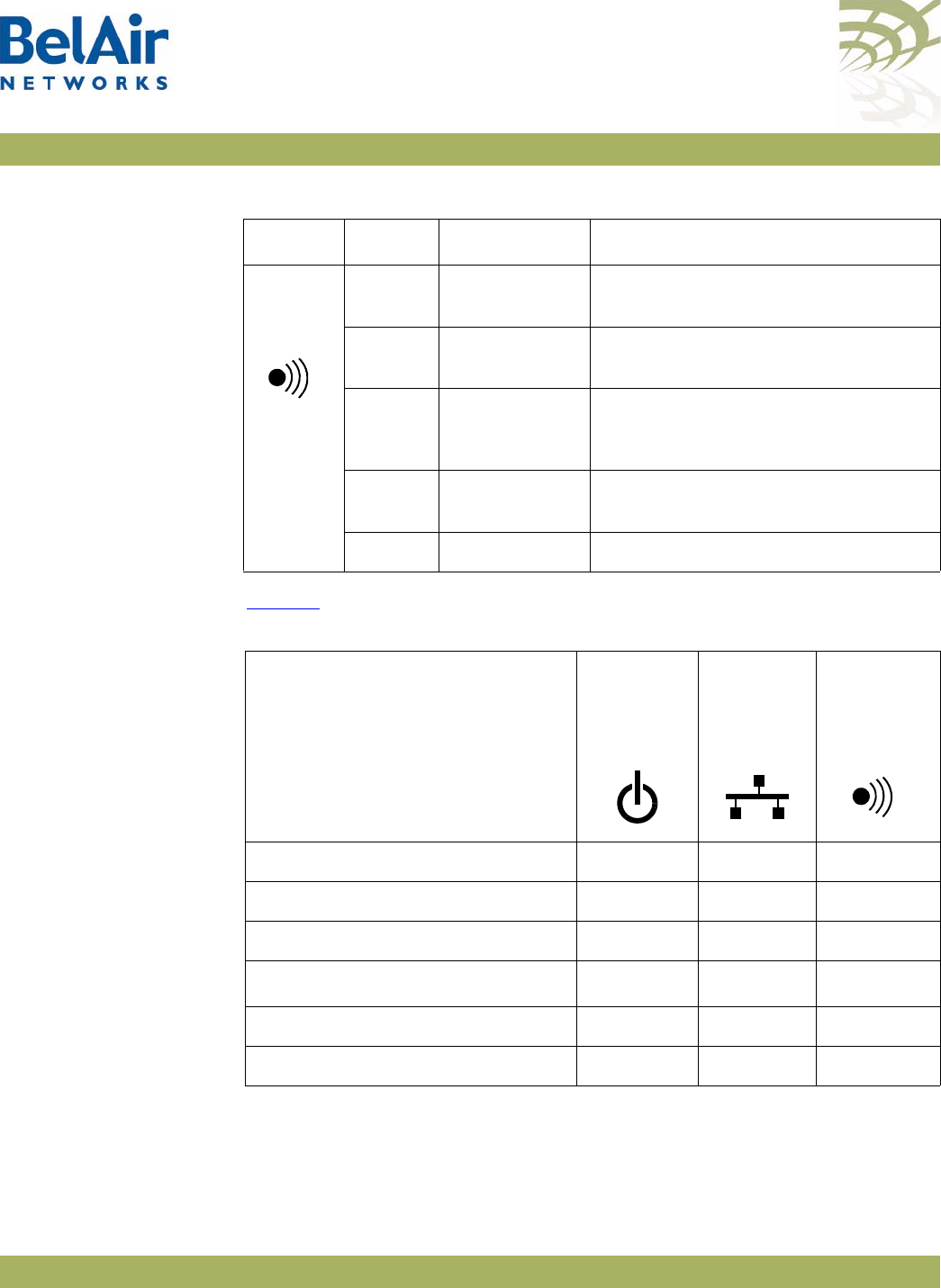
BelAirOS User Guide AP LED Descriptions
April 22, 2012 Confidential Page 290 of 362
Document Number BDTM00000-A02 Draft
BelAir100SN and
BelAir100SNE Power-up
LED Sequence
Table 25 shows the normal power-up LED sequence.
Radio or
Mesh
Off Hardware
failure Hardware failure, no power to the
unit or radio initialization
Amber Not
operational All of the P-to-P and P-to-MP links
are down.
Flashing
Amber P-to-P and/or
P-to-MP link
failure
One or more, but not all, of the
P-to-P and/or P-to-MP links are
down.
Flashing
Green MP-to-MP link
failure One or more of the MP-to-MP links
are down.
Green Operational All links are operational.
Table 26: LED Behavior - BelAir100SNE and BelAir100SNE (Continued)
LED Colour State Description
Table 27: Normal Power-Up LED Sequence
Power-up Sequence
Power Cable
Modem/
Ethernet
Radio/Mesh
Off Off Off Off
On Amber Off Off
After 1 minute Green Off Amber
After 2 minutes Green Off1Green
After 2+ minutes Green Flashing Blue Green
After 7 minutes (maximum) Green Blue Green

BelAirOS User Guide For More Information
April 22, 2012 Confidential Page 291 of 362
Document Number BDTM00000-A02 Draft
For More Information
BelAir Networks documentation is modular and organized to be of best use to
you during the logical process of setting up a network of BelAir devices.
Use the documents as outlined in the following sections.
Installation Guide Use this document when you are:
• determining infrastructure requirements
• pre-configuring the units
• installing units
• problem-solving on the site
• mounting units
• commissioning the units
BelAir OS User
Guide
Use this document when you are:
• becoming accustomed to the CLI interface
• becoming accustomed to the SNMP interface
• accessing the Web interface
• configuring the unit:
—IP parameters
—data and time
—Ethernet interfaces
• configuring the radios:
—antenna and link features
—access channel numbers
—transmission power levels
—radio transmission rates
—wireless security
• configuring Quality of Service (QoS)

BelAirOS User Guide For More Information
April 22, 2012 Confidential Page 292 of 362
Document Number BDTM00000-A02 Draft
• upgrading the unit
• saving and restoring the configuration
• troubleshooting and in need of technical support
• looking up system configuration details:
—Alarms and events
—System logs
—Statistics

BelAirOS User Guide Technical Support
April 22, 2012 Confidential Page 293 of 362
Document Number BDTM00000-A02 Draft
Technical Support
This section provides direction should you have questions about your AP.
Support
Resources
In general, BelAir Networks recommends that you do the following steps to
seek the information you want:
1 Refer to the
BelAirOS User Guide
to see if it describes your situation. If it
does, do the provided corrective actions.
2 If the user guide does not cover your situation, contact your BelAir
Networks product representative
3 If you still need assistance, use the BelAir Networks online support center
at http://support.belairnetworks.com
4 Finally, if your issue is not resolved, contact BelAir Networks:
—613-254-7070, option 2
—1-877-BelAir1 (235-2471), option 2
—techsupport@belairnetworks.com
Warranty and
Limitations
To review BelAir’s product warranty, refer to the document called
BelAir
Products Warranty and Limitations
available on the BelAir Networks Website,
or contact your BelAir Representative.

BelAirOS User Guide Definitions and Acronyms
April 22, 2012 Confidential Page 294 of 362
Document Number BDTM00000-A02 Draft
Definitions and Acronyms
ACL Access Control List
AES Advanced Encryption System
AP Access Point. A wireless LAN data transceiver that uses radio waves to provide
connectivity services to a network
Beacon A protocol packet that signals the availability and presence of a wireless device
BID Bridge identifier used in spanning-tree calculations
BPDU Bridge protocol data unit. When the spanning tree protocol is enabled, bridges
send and receive spanning-tree frames, called BPDUs, at regular intervals and
use the frames to maintain a loop-free network.
BSS Basic Service Set: A set of 802.11-compliant stations that operate as a fully
connected wireless network
Client A device that uses the services of a wireless access point to connect to a
network
CLI Command Line Interface
DHCP Dynamic Host Configuration Protocol
IP Internet Protocol
IP address The Internet Protocol (IP) address of a station. Expressed in dotted notation,
for instance, 10.21.1.14
IP subnet mask The number used to identify the IP sub-network.
LAN Local Area Network
LPM Line and Power Module
MAC Media Access Control
MAC Address Media Access Control address. A unique 48-bit number used in Ethernet data
packets to identify an Ethernet device.
MAU Medium Attachment Unit
MIB SNMP Management Information Base
MPDU MAC Protocol Data Unit
NAS Network Access Server
OAM Operations, Administration and Maintenance

BelAirOS User Guide Definitions and Acronyms
April 22, 2012 Confidential Page 295 of 362
Document Number BDTM00000-A02 Draft
OUI Organizationally Unique Identifier (first 3 bytes of a MAC address)
PVID Port VLAN identifier
PDU Protocol Data Unit
QoS Quality of Service
RADIUS Remote Authentication Dial-In User Service. An Internet protocol (RFC 2138)
for carrying dial-in users' authentication information and configuration
information between a shared, centralized authentication server (the RADIUS
server) and a network access server (the RADIUS client) that needs to
authenticate the users of its network access ports
RTS Request to Send
SNMP Simple Network Management Protocol
SNTP Simple Network Time Protocol
SSH Secure Shell
SSID Service Set Identifier (also referred to as Network Name or Id). A unique
identifier used to identify a radio network and which stations must use to be
able to communicate with each other or to an access point
SSL Secure Socket Layer
TCP Transmission Control Protocol
TKIP Temporal Key Integrity Protocol, an optional IEEE 802.11 function that offers
frame transmission privacy. Like WEP, it is based on RC4 encryption. It
generates new encryption keys for every 10 kilobytes of data transmitted.
TU Wireless Time Unit, as defined in IEEE 802.11, a measure of time equal to
1024 microseconds
UDP User Datagram Protocol
VLAN Virtual Local Area Network
WEP Wired Equivalent Privacy, an optional IEEE 802.11 function that offers frame
transmission privacy. The Wired Equivalent Privacy generates secret shared
encryption keys that both source and destination stations can use to alter frame
bits to avoid disclosure to eavesdroppers.
WPA Wi-Fi Protected Access

BelAirOS User Guide AP Configuration Sheets
April 22, 2012 Confidential Page 296 of 362
Document Number BDTM00000-A02 Draft
Appendix A: AP Configuration Sheets
You can use this sample worksheet to document the basic configuration of an
AP. Store your worksheets in a secure location because they contain sensitive
information (super-user password and privacy keys).
AP part number (located on the sticker on to the AP):__________________________
AP serial number (located on the sticker on to the AP):__________________________
Super-user password: ____________________________
System Name: ______________ Location: ____________ Contact: _______________
Base MAC Address: ______________
IP Address: _____________Subnet:______________ Gateway: ______________
Cable Modem MAC Address (BA00SN and BA100SNE only): ________________________________
Layer 2 Configuration: STP Priority: _______
Client to VLAN mapping: Y or N

BelAirOS User Guide AP Configuration Sheets
April 22, 2012 Confidential Page 297 of 362
Document Number BDTM00000-A02 Draft
Wi-FI Access Point (AP) Settings (if configured)
Interface: wifi-___-___
Channel: ________
Table 28: AP Privacy Setting Table (Optional)
SSID (1 to 8) ACL Encryption and Authentication
__________________ Y or N wep40
RADIUS or 5-byte pre-shared key: _______________________________________________
wep104
RADIUS or 13-byte pre-shared key: ______________________________________________
wpa
encryption (TKIP or AES):____________________
RADIUS or 8 to 63-byte pre-shared key: ___________________________________________
wpa2
encryption (PSMv2 only: TKIP or AES. Others: AES only):____________________
RADIUS or 8 to 63-byte pre-shared key: ___________________________________________
dot1x (RADIUS (EAP) authentication)
1. ________________
2. ________________
3. ________________
4. ________________

BelAirOS User Guide AP Configuration Sheets
April 22, 2012 Confidential Page 298 of 362
Document Number BDTM00000-A02 Draft
Wi-Fi Backhaul Setting (if configured)
Interface: wifi-___-___
Channel: ________
Link ID: _____________________
AES Privacy (Y or N):__________ Key (16 characters):_____________________________________
Topology (P-to-P, MP-to-MP mesh, P-to-MP star): ________________________________
P-to-MP star role (base-station or subscriber-station): ____________________________
P-to-MP star link index: ____________________________
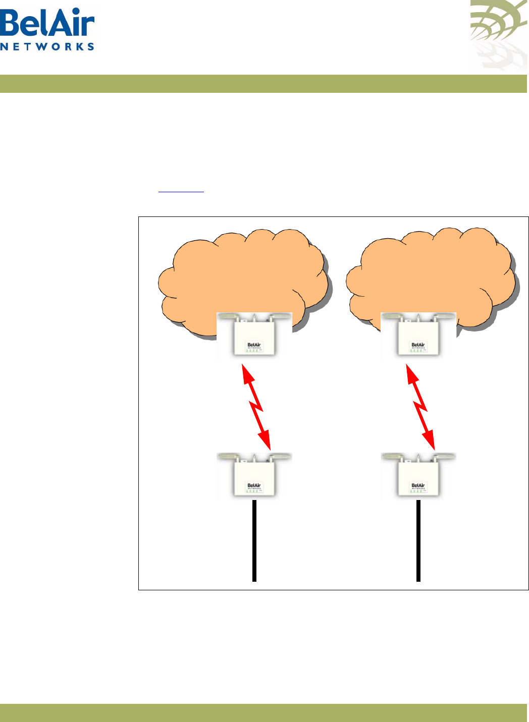
BelAirOS User Guide Mesh Auto-connection Example
April 22, 2012 Confidential Page 299 of 362
Document Number BDTM00000-A02 Draft
Appendix B: Mesh Auto-connection Example
This example uses two meshes of BelAir20 APs to show how mesh
auto-connection operates.
Setup and Initial
Conditions
See Figure 29.
Figure 29: Auto-connection Initial Conditions
To setup auto-connection:
• The first six bytes of the respective link IDs must match. This is true in our
example (
B20MeshA
and
B20MeshB
).
• The auto-connection admin state in the child APs must be enabled.
AP123
BelAir20
Child
AP121
BelAir20
Egress
BA20MeshB
Link ID
Ethernet
Egress
Connection
AP122
BelAir20
Child
AP120Bel
Air20
Egress
BA20MeshA
Link ID
Ethernet
Egress
Connection
Mesh A Mesh B

BelAirOS User Guide Mesh Auto-connection Example
April 22, 2012 Confidential Page 300 of 362
Document Number BDTM00000-A02 Draft
• The egress AP of each mesh must have its system egress point set to either
yes direct
or
yes indirect
. See “Setting the Network Egress Point” on
page 72 for details.
The following series of CLI commands show this for both meshes.
AP122 (Child AP of Mesh A)
Display the backhaul configuration.
/interface/wifi-1-1# show config backhaul
Slot: 1, Card Type: htm, revision: 1, Port: 1, Radio: HTMv1 5GHz 802.11n
admin state: ................. Enabled
channel: ..................... 161
mode: ...................... ht20
mimo: ...................... 3x3
tx power: .................. 18.0 (dBm per-chain), 23.0 (dBm total)
antenna gain: ................ 5.0 (dBi)
link distance: ............... 1 (km)
tx aggregation:............... Enabled
base radio MAC : ............. 00:0d:67:10:e8:92
Backhaul:
Common:
privacy: ................. Disabled
mesh-min-rssi............. -100 (dbm)
Stationary Backhaul:
link admin state: ........ Enabled
link id: ................. B20MeshA
topology: ................ mesh
Mobile Backhaul:
mobile admin state: ...... Disabled
mobile link id: ..........
mobile link role: ........ ss
Protection Backhaul:
protection admin state: .. Disabled
Blacklist:
No blacklist entries
Link Failure Detection: ...... Disabled
Backhaul T1 Bandwidth limit:.. Disabled
Display the mesh topology.
/interface/wifi-1-1# show backhaul status
WiFi backhaul states:: stationary=[Enabled] mobile=[Disabled] protection=[Disabled]
Backhaul Links:
Link Radio Mac State(L,R) RSSI Radio Node IP Node Name
----- ----------------- ---------- ---- ----- -------- ----------
[S] 1 00:0d:67:0c:22:4b fwd fwd -46 wifi-1-1 180.7.4.120

BelAirOS User Guide Mesh Auto-connection Example
April 22, 2012 Confidential Page 301 of 362
Document Number BDTM00000-A02 Draft
Enable auto-connection and verify it.
/services/auto-conn# set admin enabled
/services/auto-conn# show config
admin state: ................. Enabled
/services/auto-conn# show status
Oper State Ether Link State Egress Reachable Use Alternate Mesh
----------- ---------- ---------------- ----------------
up down no no
AP120 (Egress AP of Mesh A)
Display the mesh topology.
/interface/wifi-1-1# show backhaul status
WiFi backhaul states:: stationary=[Enabled] mobile=[Disabled] protection=[Disabled]
Backhaul Links:
Link Radio Mac State(L,R) RSSI Radio Node IP Node Name
----- ----------------- ---------- ---- ----- -------- ----------
[S] 1 00:0d:67:10:e8:92 fwd fwd -44 wifi-1-1 180.7.4.122
Identify AP120 as an egress AP.
/system# set system-egress-point yes direct
/system# show system-egress-point
egress point:................. direct
Enable auto-connection and verify it.
/services/auto-conn# set admin enable
/services/auto-conn# show config
admin state: ................. Enabled
/services/auto-conn# show status
Oper State Ether Link State Egress Reachable Use Alternate Mesh
----------- ---------- ---------------- ----------------
up up yes no
AP123 (Child AP of Mesh B)
Display the backhaul configuration.
/interface/wifi-1-1# show config backhaul
Slot: 1, Card Type: htm, revision: 1, Port: 1, Radio: HTMv1 5GHz 802.11n
admin state: ................. Enabled
channel: ..................... 153
mimo: ...................... 1x1
tx power: .................. 18.0 (dBm per-chain), 18.0 (dBm total)
antenna gain: ................ 5.0 (dBi)
link distance: ............... 1 (km)
tx aggregation:............... Enabled
base radio MAC : ............. 00:0d:67:10:f8:d7
Backhaul:

BelAirOS User Guide Mesh Auto-connection Example
April 22, 2012 Confidential Page 302 of 362
Document Number BDTM00000-A02 Draft
Common:
privacy: ................. Disabled
mesh-min-rssi............. -100 (dbm)
Stationary Backhaul:
link admin state: ........ Enabled
link id: ................. B20MeshB
topology: ................ mesh
Mobile Backhaul:
mobile admin state: ...... Disabled
mobile link id: ..........
mobile link role: ........ ss
Protection Backhaul:
protection admin state: .. Disabled
Blacklist:
No blacklist entries
Link Failure Detection: ...... Disabled
Backhaul T1 Bandwidth limit:.. Disabled
Display the mesh topology.
/interface/wifi-1-1# show backhaul status
WiFi backhaul states:: stationary=[Enabled] mobile=[Disabled] protection=[Disabled]
Backhaul Links:
Link Radio Mac State(L,R) RSSI Radio Node IP Node Name
----- ----------------- ---------- ---- ----- -------- ----------
[S] 1 00:0d:67:0c:22:29 fwd fwd -49 wifi-1-1 180.7.4.121
Enable auto-connection and verify it.
/services/auto-conn# set admin enabled
/services/auto-conn# show config
admin state: ................. Enabled
/services/auto-conn# show status
Oper State Ether Link State Egress Reachable Use Alternate Mesh
----------- ---------- ---------------- ----------------
up down no no
AP121 (Egress AP of Mesh B)
Display the mesh topology.
/interface/wifi-1-1# show backhaul status
WiFi backhaul states:: stationary=[Enabled] mobile=[Disabled] protection=[Disabled]
Backhaul Links:
Link Radio Mac State(L,R) RSSI Radio Node IP Node Name
----- ----------------- ---------- ---- ----- -------- ----------
[S] 1 00:0d:67:10:f8:d7 fwd fwd -41 wifi-1-1 180.7.4.123

BelAirOS User Guide Mesh Auto-connection Example
April 22, 2012 Confidential Page 303 of 362
Document Number BDTM00000-A02 Draft
Identify AP121 as an egress AP.
/system# set system-egress-point yes direct
/system# show system-egress-point
egress point:................. direct
Enable auto-connection and verify it.
/services/auto-conn# set admin enable
/services/auto-conn# show config
admin state: ................. Enabled
/services/auto-conn# sh status
Oper State Ether Link State Egress Reachable Use Alternate Mesh
----------- ---------- ---------------- ----------------
up up yes no
Fault Conditions At this point, the Ethernet connection used by the Mesh B egress AP (AP121)
becomes unavailable. The “Mesh B” APs (AP121 and AP123) connect to the
Mesh A APs and all traffic flows through the Mesh A egress AP (AP120). AP121
and AP123 become members of Mesh A. See Figure 30 on page 304.
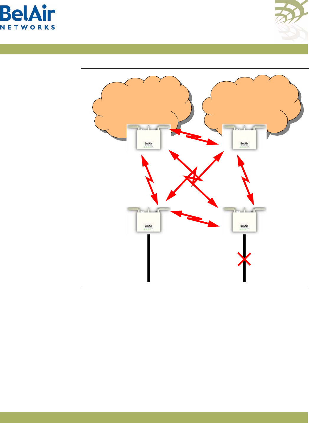
BelAirOS User Guide Mesh Auto-connection Example
April 22, 2012 Confidential Page 304 of 362
Document Number BDTM00000-A02 Draft
Figure 30: Auto-connection and Fault Conditions
AP120 (Egress AP of Mesh A)
Display the mesh topology.
/interface/wifi-1-1# show backhaul status
WiFi backhaul states:: stationary=[Enabled] mobile=[Disabled] protection=[Disabled]
Backhaul Links:
Link Radio Mac State(L,R) RSSI Radio Node IP Node Name
----- ----------------- ---------- ---- ----- -------- ----------
[S] 1 00:0d:67:10:e8:92 fwd up -46 wifi-1-1 180.7.4.122
[S] 2 00:0d:67:0c:22:29 fwd fwd -36 wifi-1-1 180.7.4.121
[S] 3 00:0d:67:10:f8:d7 fwd up -64 wifi-1-1 180.7.4.123
AP123
BelAir20
Child
AP121
BelAir20
Egress
BA20MeshB
Link ID
Ethernet
Egress
Connection
AP122
BelAir20
Child
AP120Bel
Air20
Egress
BA20MeshA
Link ID
Ethernet
Egress
Connection
Mesh A Mesh B

BelAirOS User Guide Mesh Auto-connection Example
April 22, 2012 Confidential Page 305 of 362
Document Number BDTM00000-A02 Draft
Display the auto-connect topology. It shows that the Mesh A egress AP still
operates normally.
/services/auto-conn# show status
Oper State Ether Link State Egress Reachable Use Alternate Mesh
----------- ---------- ---------------- ----------------
up up yes no
AP122 (Child AP of Mesh A)
Display the mesh topology.
/interface/wifi-1-1# show backhaul status
WiFi backhaul states:: stationary=[Enabled] mobile=[Disabled] protection=[Disabled]
Backhaul Links:
Link Radio Mac State(L,R) RSSI Radio Node IP Node Name
----- ----------------- ---------- ---- ----- -------- ----------
[S] 1 00:0d:67:0c:22:4b up fwd -51 wifi-1-1 180.7.4.120
[S] 2 00:0d:67:0c:22:29 fwd fwd -41 wifi-1-1 180.7.4.121
[S] 3 00:0d:67:10:f8:d7 fwd up -58 wifi-1-1 180.7.4.123
Display the auto-connect topology.
/services/auto-conn# show status
Oper State Ether Link State Egress Reachable Use Alternate Mesh
----------- ---------- ---------------- ----------------
up down yes no
AP123 (Child AP of Mesh B)
Display the backhaul configuration.
/interface/wifi-1-1# show config backhaul
Slot: 1, Card Type: htm, revision: 1, Port: 1, Radio: HTMv1 5GHz 802.11n
admin state: ................. Enabled
channel: ..................... 153
mimo: ...................... 1x1
tx power: .................. 18.0 (dBm per-chain), 18.0 (dBm total)
antenna gain: ................ 5.0 (dBi)
link distance: ............... 1 (km)
tx aggregation:............... Enabled
base radio MAC : ............. 00:0d:67:10:f8:d7
Backhaul:
Common:
privacy: ................. Disabled
mesh-min-rssi............. -100 (dbm)
Stationary Backhaul:
link admin state: ........ Enabled
link id: ................. B20MeshB
topology: ................ mesh
Mobile Backhaul:

BelAirOS User Guide Mesh Auto-connection Example
April 22, 2012 Confidential Page 306 of 362
Document Number BDTM00000-A02 Draft
mobile admin state: ...... Disabled
mobile link id: ..........
mobile link role: ........ ss
Protection Backhaul:
protection admin state: .. Disabled
Blacklist:
No blacklist entries
Link Failure Detection: ...... Disabled
Backhaul T1 Bandwidth limit:.. Disabled
Display the mesh topology.
/interface/wifi-1-1# show backhaul status
WiFi backhaul states:: stationary=[Enabled] mobile=[Disabled] protection=[Disabled]
Backhaul Links:
Link Radio Mac State(L,R) RSSI Radio Node IP Node Name
----- ----------------- ---------- ---- ----- -------- ----------
[S] 1 00:0d:67:10:e8:92 up fwd -58 wifi-1-1 180.7.4.122
[S] 2 00:0d:67:0c:22:29 fwd fwd -47 wifi-1-1 180.7.4.121
[S] 3 00:0d:67:0c:22:4b up fwd -67 wifi-1-1 180.7.4.120
Display the auto-connect topology.
/services/auto-conn# show status
Oper State Ether Link State Egress Reachable Use Alternate Mesh
----------- ---------- ---------------- ----------------
up down yes yes
AP121 (Egress AP of Mesh B)
Display the auto-connect topology. It shows that it is using the alternate mesh
as an egress point.
/services/auto-conn# show status
Oper State Ether Link State Egress Reachable Use Alternate Mesh
----------- ---------- ---------------- ----------------
up down yes yes
Recovery
Conditions
At this point, the Ethernet connection used by the Mesh B egress AP (AP121) is
re-established. Because it is an egress AP, AP121 automatically reverts back to
its own mesh and begins to use the Ethernet connection to egress its traffic.
However, its child APs (for example, AP123) continue to use the Mesh A egress
AP until an explicit revert command is issued on each child you want to return
to using AP121 as an egress.

BelAirOS User Guide Mesh Auto-connection Example
April 22, 2012 Confidential Page 307 of 362
Document Number BDTM00000-A02 Draft
AP121 (Egress AP of Mesh B)
Display the auto-connect topology after the Ethernet connection is
re-established.
/services/auto-conn# show status
Oper State Ether Link State Egress Reachable Use Alternate Mesh
----------- ---------- ---------------- ----------------
up up yes no
Display the AP’s links to neighboring mesh, even after the Ethernet connection
is re-established.
/services/auto-conn# show alternate-mesh
Alternate Mesh:
Radio Interface --- wifi-1-1
Mesh ID --- B20MeshA
Channel --- 161
Status --- Up
AP122 (Child AP of Mesh A)
Display the mesh topology after the Ethernet connection is re-established on
AP121 but before the auto-connection revert command is given.
/interface/wifi-1-1# show backhaul status
WiFi backhaul states:: stationary=[Enabled] mobile=[Disabled] protection=[Disabled]
Backhaul Links:
Link Radio Mac State(L,R) RSSI Radio Node IP Node Name
----- ----------------- ---------- ---- ----- -------- ----------
[S] 1 00:0d:67:0c:22:4b fwd fwd -49 wifi-1-1 180.7.4.120
[S] 3 00:0d:67:10:f8:d7 fwd fwd -58 wifi-1-1 180.7.4.123
See Figure 31 on page 308.
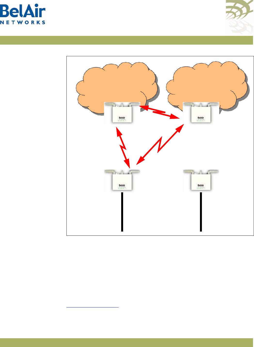
BelAirOS User Guide Mesh Auto-connection Example
April 22, 2012 Confidential Page 308 of 362
Document Number BDTM00000-A02 Draft
Figure 31: Auto-connection after Recovery before Revert
Display the mesh topology after the Ethernet connection is re-established on
AP121 and after the auto-connection revert command is given.
/interface/wifi-1-1# show backhaul status
WiFi backhaul states:: stationary=[Enabled] mobile=[Disabled] protection=[Disabled]
Backhaul Links:
Link Radio Mac State(L,R) RSSI Radio Node IP Node Name
----- ----------------- ---------- ---- ----- -------- ----------
[S] 1 00:0d:67:0c:22:4b fwd fwd -49 wifi-1-1 180.7.4.120
After the revert command is given, the mesh topology returns to that shown in
Figure 29 on page 299.
AP123
BelAir20
Child
AP121
BelAir20
Egress
BA20MeshB
Link ID
Ethernet
Egress
Connection
AP122
BelAir20
Child
AP120Bel
Air20
Egress
BA20MeshA
Link ID
Ethernet
Egress
Connection
Mesh A Mesh B

BelAirOS User Guide Scripting Guidelines
April 22, 2012 Confidential Page 309 of 362
Document Number BDTM00000-A02 Draft
Appendix C: Scripting Guidelines
This appendix provides guidance so you can create, manage and run scripts for
BelAirOS™ platforms.
General Scripting
Guidelines
This chapter introduces you to the concepts of creating and managing scripts
for platforms that use the BelAirOS. The following sections are provided:
•“Overview” on page 309
•“Creating a BelAirOS Script” on page 309
•“Manually Transferring Files to and from an AP” on page 310
•“Managing and Manually Running Script Files” on page 311
Overview In general, a script is a series of programming language statements to allow
control of one or more software applications or devices. Scripts are distinct
from the core code of an application, as they are created by the end-user.
Scripts are often interpreted, whereas the applications they control are
traditionally compiled to native machine code.
For BelAirOS APs you can create scripts consisting of valid and supported CLI
commands to:
• make repetitive tasks quicker and easier to do
• automate the configuration of an AP when it starts up
Your script file must contain special declarations for the following cases:
• If you want to specify and control physical interfaces, such as
wifi-1-1
, use
the declarations described in “Specifying Physical Interfaces” on page 312.
• Depending on the CLI commands in your script, you may need to reboot
the BelAirOS AP. If this case, use the declarations described in “Including a
Reboot Command in a Script” on page 316.
Creating a BelAirOS
Script Use the following general guidelines to create a script file:
• Make sure the script contains only valid and supported CLI commands. If
you are using an older script, make sure the CLI commands that it contains
are still valid and supported.
• Some functions, such as Network Address Translation (NAT), require that
you reboot the AP after you configure them. If your script is for
auto-configuration at startup and if it must include the
reboot
command,

BelAirOS User Guide Scripting Guidelines
April 22, 2012 Confidential Page 310 of 362
Document Number BDTM00000-A02 Draft
then your script must include special declarations. For details, see “Including
a Reboot Command in a Script” on page 316.
Caution! Using the
reboot
command in an auto-configuration script without the correct
declarations may cause the AP to enter a continuous
reboot
loop.
• Test the final script to ensure all commands are valid, syntactically correct
and appropriate for the installed hardware. To help debugging, redirect the
output of the script to a file. Use the optional
<output_file>
parameter of
the
run script
command.
When you are satisfied with your script:
1 Put the final version of it on a TFTP, FTP or FTPS server to transfer the
script file to the AP.
2 Use the commands described in “Manually Transferring Files to and from an
AP” on page 310 to transfer the script to the APs you want to control.
3 Use the commands described in “Managing and Manually Running Script
Files” on page 311 as required.
The process of downloading and running a script file on startup can be
automated. For details, see the “AP Auto-configuration” on page 78.
Manually Transferring
Files to and from an AP Use the following CLI commands to manually transfer files, such as script files,
to and from an AP:
/system/tftpget remoteip <ip_addr> remotefile <filename>
[localfile <filename>]
/system/tftpput remoteip <ip_addr> localfile <filename>
[remotefile <name>]
/system/getfile remoteip <ip_addr> remotefile <filename>
[localfile <filename>]
[{tftp|
ftp [user <username> password <password>]|
ftps [user <username> password <password>]}]
For the
tftpget
and
getfile
commands, if you do not specify a local file name,
then the transferred file maintains the same name as on the remote file system.
For the
tftpput
command, if you do not specify a remote file name, then the
transferred file maintains the same name as on the local file system.
For the
getfile
command:
• The default protocol is TFTP.
• For FTP, the default user name is
anonymous
and the default password is
root@
followed by the AP IP address. For example, if the AP has
148.16.4.123 as an IP address, then the default password is
root@148.16.4.123.

BelAirOS User Guide Scripting Guidelines
April 22, 2012 Confidential Page 311 of 362
Document Number BDTM00000-A02 Draft
• For FTPS, the default user name is the AP’s MAC address stripped of colons.
The default password is AP’s MAC address stripped of colons, followed by
@, followed by the AP IP address. For example, if the AP has
11:22:33:44:55:66 as a MAC address and 148.16.4.123 as an IP address, then
the default user name is 112233445566 and the default password is
112233445566@148.16.4.123.
CAUTION! Do not use these commands to perform a software upgrade on an AP. Use the
upgrade load command instead. Refer to “Performing a Software Upgrade” on
page 246 for full details on performing software upgrades.
Managing and Manually
Running Script Files Use the following commands as required:
/system/copy script <script file> <copied file name>
/system/delete script <script file>
/system/rename script <script file> <new name>
/system/show script <script file>
list scripts
run script <scriptname> [<output_file>]
The
copy
,
delete
,
rename
and
show script
commands are available in
system
mode and allow you to manage and customize script files as you require.
The
list
and
run script
commands are available from any mode. The
list scripts
command displays the scripts that are available to you. The
run script
command
allows you to execute a previously created script file.
Tip
If you have a simple script that does not specify physical interfaces and does not
contain a
reboot
command, you can also run it by copying it and pasting it into
a CLI session window. If you use this method:
1 Paste only 20 to 25 commands at a time. Otherwise, you may overfill the
command buffer used for the CLI session. If you overfill the command buffer,
you need to determine exactly which commands were executed and which
were not before proceeding.
2 After pasting a block of commands, verify that your script behaved as
expected; that is, that the pasted commands produced the expected
configuration.
3 After verifying the script behavior, manually enter the
config-save
and
reboot
commands as required.

BelAirOS User Guide Scripting Guidelines
April 22, 2012 Confidential Page 312 of 362
Document Number BDTM00000-A02 Draft
Specifying Physical
Interfaces
If you want your script file to specify and control physical interfaces, such as
wifi-1-1
, then your script must contain the declarations described in the
following sections:
•“Physical Interface Declaration Summary” on page 312
•“Physical Interface Declaration Specifications” on page 312
As well, this chapter contains examples of the setup, contents and results of a
typical script.
Physical Interface
Declaration Summary Table 29 summarizes the declarations required in your script file to specify a
physical interface.
Physical Interface
Declaration
Specifications
Script files can use the following method to ensure commands are applied to
the correct physical interface:
1 Begin the command sequence by specifying the physical interface with the
following declaration:
int[-<asbly>]-<iftype>[-<desc>]-<instance>
Table 29: BelAir Networks Script Declaration Summary
Script Declaration Description
int[-<asbly>]-<iftype>[-<desc>]-<instance> Used to define a physical interface to which the
following CLI commands apply to.
For a definition of
<asbly>
,
<iftype>
,
<desc>
,
and
<instance>
, see “Physical Interface
Declaration Specifications” on page 312.
/Precedes a CLI command that is not directed to
the specified physical interface. The CLI command
must start with a slash (/) followed by the mode(s)
containing that command.
For details, see “Physical Interface Declaration
Specifications” on page 312.
int-stop Terminates a command sequence associated with
a previous declaration

BelAirOS User Guide Scripting Guidelines
April 22, 2012 Confidential Page 313 of 362
Document Number BDTM00000-A02 Draft
<asbly> specifies the AP’s assembly code. This part of the declaration is
optional. If provided, it must match at least part of the text in the
Assembly
code
field output by the
/system/show phyinv
command. <asbly> must start
with
BelAir
or
BA
. See also “Common AP Assembly Codes” on page 319.
<iftype> specifies the type of physical interface. This part of the declaration
is mandatory. It must be one of
wifi
,
wimax
,
pwe
,
eth
or
opt.
<desc> specifies a description of the interface to uniquely identify it. This
part of the declaration is optional. If provided, it must be at least three
characters long and match at least part of the text in the
Description
field in
the Physical Interface Table output by the
/system/show phyinv
command.
See also “Common Radio Card Descriptions” on page 320.
<instance> specifies which instance of the interface to apply the commands
to. It must be a digit between 1 and 127.
Use a dash ( - ) to separate each part in the declaration.
The system uses the information in your declaration to determine which
physical interface the following commands apply to.
2 List the CLI commands. These may be commands directed to the physical
interface specified by step 1 or they may be other commands. Any
commands not directed to the specified physical interface must start with a
slash ( / ) followed by the mode(s) containing that command. In all cases,
make sure you follow the guidelines in “Creating a BelAirOS Script” on
page 309.
3 Terminate the command sequence with the following declaration:
int-stop
If the AP cannot identify a physical interface based on the information in the
int
declaration, then it skips the list of commands and continues executing the
script after the
int-stop
declaration.
The following example shows the setup, script and output of a typical
application of this functionality for a BelAir100T.
Physical Interface Script
Example - Setup The following output of the
show phyinv
command shows the configuration of
the BelAir100T where the script will run:
/system# show phyinv
System Name: BelAir100T
Type Class Serial number Assembly code BA order code
BelAir100 triRadios BELAB0407 BELAIR100T_20-BC08 1TNYYXJ0KXX31-H

BelAirOS User Guide Scripting Guidelines
April 22, 2012 Confidential Page 314 of 362
Document Number BDTM00000-A02 Draft
Physical Inventory Table
Slot Card type Version Serial number Assembly code
1 LPM 2.2.8 K002092633 B2CH082AA-B B08
2 BRM 3.2.1 K001362023 B2CC033AA-B B01
3 BRM 3.2.1 A000003408 B2CC033AA-B B01
Physical Interface Table
Name Type Slot Card type Description
wifi-1-1 Wifi 802.11 1 LPM LPMv2 4.9GHz 802.11a
eth-1-1 Ethernet 1 LPM 1x100baseTx [Electrical: Single]
wifi-2-1 Wifi 802.11 2 BRM BRMv3 5GHz 802.11a
wifi-3-1 Wifi 802.11 3 BRM BRMv3 5GHz 802.11a
Physical Interface Script
Example - Script The following is a listing of the script contents:
int-wifi-2.4GHz-1
set channel 11
set admin-state enabled
show config
int-stop
int-wifi-4.9GHz-1
set channel 10
set admin-state disabled
show config
int-stop
int-wifi-5GHz-1
set channel 155
set backhaul admin-state disabled
show config
int-stop
int-wifi-5GHz-2
set channel 148
set backhaul admin-state disabled
show config
int-stop
int-BELAIR100T_20-wifi-5GHz-1
show config
int-stop
int-BELAIR20-11-wifi-5GHz-1
show config
int-stop
int-BELAIR100-wifi-1
show config
int-stop
Physical Interface Script
Example - Output The following shows the output generated by the script:
Unknown interface ---> int-wifi-2.4GHz-1, skipping

BelAirOS User Guide Scripting Guidelines
April 22, 2012 Confidential Page 315 of 362
Document Number BDTM00000-A02 Draft
Interface stop
/#
Interface int-wifi-4.9GHz-1 ---> /interface/wifi-1-1/ start
/# /interface/wifi-1-1/set channel 10
/# /interface/wifi-1-1/set admin-state disabled
/# /interface/wifi-1-1/show config
Slot: 1, Card Type: lpm, revision: 2, Port: 1, Radio: LPMv2 4.9GHz 802.11a
admin state: ................. Disabled
frequency band: .............. 4900MHz SchemeA
channel: ..................... 10
tx power: .................. 20.0 (dBm)
bandwidth: ................. 10.0 (MHz)
antenna gain: ................ 9.5 (dBi)
link distance: ............... 1 (km)
base radio MAC : ............. 00:0d:67:00:48:52
Interface stop
/#
Interface int-wifi-5GHz-1 ---> /interface/wifi-2-1/ start
/# /interface/wifi-2-1/set channel 155
/# /interface/wifi-2-1/set backhaul admin-state disabled
/# /interface/wifi-2-1/show config
Slot: 2, Card Type: brm, revision: 3, Port: 1, Radio: BRMv3 5GHz 802.11a
admin state: ................. Enabled
channel: ..................... 155
tx power: .................. 20.0 (dBm)
tx-power-optimize: ......... Disabled
antenna gain: ................ 10.5 (dBi)
link distance: ............... 1 (km)
base radio MAC : ............. 00:0d:67:00:44:49
Interface stop
/#
Interface int-wifi-5GHz-2 ---> /interface/wifi-3-1/ start
/# /interface/wifi-3-1/set channel 148
/# /interface/wifi-3-1/set backhaul admin-state disabled
/# /interface/wifi-3-1/show config
Slot: 3, Card Type: brm, revision: 3, Port: 1, Radio: BRMv3 5GHz 802.11a
admin state: ................. Enabled
channel: ..................... 148
tx power: .................. 20.0 (dBm)
tx-power-optimize: ......... Disabled
antenna gain: ................ 10.5 (dBi)
link distance: ............... 1 (km)
base radio MAC : ............. 00:0d:67:00:c4:6b

BelAirOS User Guide Scripting Guidelines
April 22, 2012 Confidential Page 316 of 362
Document Number BDTM00000-A02 Draft
Interface stop
/#
Interface int-BELAIR100T_20-wifi-5GHz-1 ---> /interface/wifi-2-1/ start
/# /interface/wifi-2-1/show config
Slot: 2, Card Type: brm, revision: 3, Port: 1, Radio: BRMv3 5GHz 802.11a
admin state: ................. Enabled
channel: ..................... 155
tx power: .................. 20.0 (dBm)
tx-power-optimize: ......... Disabled
antenna gain: ................ 10.5 (dBi)
link distance: ............... 1 (km)
base radio MAC : ............. 00:0d:67:00:44:49
Interface stop
/#
assembly code tag does not match
Unknown interface ---> int-BELAIR20-11-wifi-5GHz-1, skipping
Interface stop
/#
Interface int-BELAIR100-wifi-1 ---> /interface/wifi-1-1/ start
/# /interface/wifi-1-1/show config
Slot: 1, Card Type: lpm, revision: 2, Port: 1, Radio: LPMv2 4.9GHz 802.11a
admin state: ................. Disabled
frequency band: .............. 4900MHz SchemeA
channel: ..................... 10
tx power: .................. 20.0 (dBm)
bandwidth: ................. 10.0 (MHz)
antenna gain: ................ 9.5 (dBi)
link distance: ............... 1 (km)
base radio MAC : ............. 00:0d:5e:36:88:ff
Interface stop
/#
Including a
Reboot
Command in a
Script
Some functions, such as Network Address Translation (NAT), require that you
reboot the AP after you configure them. If your script must include a
reboot
command, then your script must contain the declarations described in the
following sections:
•“Reboot Declaration Summary” on page 317
•“Reboot Declaration Specification” on page 317
As well, this chapter contains a typical script as an example.

BelAirOS User Guide Scripting Guidelines
April 22, 2012 Confidential Page 317 of 362
Document Number BDTM00000-A02 Draft
Reboot Declaration
Summary Table 29 summarizes the declarations required in your script if it needs to
include a
reboot
command.
Reboot Declaration
Specification If your script must include the
reboot
command, then your script must include
the declarations described in this section.
Caution! Using the
reboot
command in an auto-configuration script without the correct
declarations may cause the AP to enter a continuous
reboot
loop.
The declarations for using the
reboot
command in a script are an extension of
those for specifying a physical interface in a script. See “Specifying Physical
Interfaces” on page 312.
The declarations are:
•
check-db-change-start
. This declaration verifies and records whether the
following commands change the AP’s settings. It ignores commands that
change a setting to be the current setting. For example, if a physical
interface’s administrative state is enabled, the s
et admin-state enabled
command for that physical interface is ignored.
•
check-db-change-stop
. This declaration stops verifying whether commands
change the AP’s setting.
Table 30: Script Declaration Summary for Reboot Command
Script Declaration Description
check-db-change-start Verifies and records whether the following commands change the AP’s
settings.
For details, see “Reboot Declaration Specification” on page 317
check-db-change-stop Stops verifying whether commands change the AP’s settings.
For details, see “Reboot Declaration Specification” on page 317
int-db-change-start Used in conjunction with the previous
check-db-change
declarations.
The
int-db-change-start
declaration instructs the AP to execute the
commands that follow if the AP’s settings have changed.
For details, see “Reboot Declaration Specification” on page 317
int-stop Terminates a command sequence associated with a previous declaration

BelAirOS User Guide Scripting Guidelines
April 22, 2012 Confidential Page 318 of 362
Document Number BDTM00000-A02 Draft
•
int-db-change-start
. This declaration is used with the previous
check-db-change
declarations. The
int-db-change-start
declaration instructs
the AP to execute the commands that follow if the AP’s settings have
changed.
Typically, your script uses the declarations in the following sequence:
1 Use valid CLI commands and physical interface declarations as required.
2Use the
config-save
command to save the changes to this point to the AP’s
database.
3 Include the
check-db-change-start
declaration. (Begin recording whether the
following commands change the APs settings.)
4 Use the CLI commands for the functionality that requires a reboot, for
example
/protocol/nat/set
commands.
5 Include the
check-db-change-stop
declaration. (Stop recording whether the
following commands change the AP’s settings.)
6 Use more valid CLI commands and physical interface declarations as
required.
7 At the end of the script, include the
int-db-change-start
declaration.
8Use the
config-save
command to save any remaining changes to the AP’s
database.
9 Include the
/system/reboot
CLI command.
10 Include
y
. (Confirm the reboot.)
11 Include the
int-stop
declaration, as a terminator for the
int-db-change-start
declaration.
The first time the auto-configuration script is run (during initial startup), the
check-db-change-start
and
check-db-change-stop
declarations record the fact
that the NAT commands have changed NAT settings. The condition for the
int-db-change-start
declaration is therefore true. The
config-save
and
reboot
commands at the end of the script are executed. The second time the
auto-configuration script is run (during the second startup), the NAT
commands do not change the NAT settings. Hence the condition for the
int-db-change-start
declaration is false, and the
config-save
and
reboot
commands at the end of the script are not executed.
Reboot Script Example The following is a listing of a typical script:
int-wifi-2.4GHz-1
set channel 11
set admin-state enabled

BelAirOS User Guide Scripting Guidelines
April 22, 2012 Confidential Page 319 of 362
Document Number BDTM00000-A02 Draft
show config
int-stop
int-wifi-5GHz-1
set channel 155
set backhaul admin-state disabled
show config
config-save
int-BELAIR-20
check-db-change-start
/protocol/nat/set scope 1 dhcp-server vlan 401 based-ip 45.89.233.0 lease-time 30
/protocol/nat/set scope 1 status enabled
/protocol/nat/set admin-state enabled
check-db-change-stop
int-stop
int-db-change-start
config-save
/system/reboot
y
int-stop
Common AP
Assembly Codes
This section lists the most common AP assembly codes that can be used when
specifying a physical interface in a script. Additional assembly codes are
possible. For details, contact your BelAir Networks representative.
Table 31: Common AP Assembly Codes
AP Assembly Code
BelAir200-12 BELAIR200_12
BelAir200-13 BELAIR200_13
BelAir200-04 BELAIR200_04
BelAir200-13R BELAIR200_13R
BelAir100-10 BELAIR100_10
BelAir100-11 BELAIR100_11
BelAir100M-10 BELAIR100M_10
BelAir100M-11 BELAIR100M_11

BelAirOS User Guide Scripting Guidelines
April 22, 2012 Confidential Page 320 of 362
Document Number BDTM00000-A02 Draft
BelAir100T-12 BELAIR100T_12
BelAir100T-21 BELAIR100T_21
BelAir100T-12R BELAIR100T_12R
BelAir100T-21R BELAIR100T_21R
BelAir100S-10 BELAIR100S_10
BelAir100S-11 BELAIR100S_11
BelAir100N-10 BA100N-10
BelAir100N-11 BA100N-11
BelAir100N-10R BA100N-10R
BelAir100N-11R BA100N-11R
BelAir100SN-10 BA100SN-10
BelAir100SN-11 BA100SN-11
BelAir100SN-10R BA100SN-10R
BelAir100SN-11R BA100SN-11R
BelAir20-11 BELAIR20-11
Table 31: Common AP Assembly Codes (Continued)
AP Assembly Code

BelAirOS User Guide Scripting Guidelines
April 22, 2012 Confidential Page 321 of 362
Document Number BDTM00000-A02 Draft
Common Radio
Card
Descriptions
This section lists the most common card descriptions for radios so you can
specify a physical interface in a script. Additional card descriptions are possible.
For details contact your BelAir Networks representative.
Table 32: Common Radio Card Descriptions
Card Description Notes
ARMv3 ARMv3 2.4GHz 802.11b/g
BRMv3 BRMv3 5GHz 802.11a
BRMv4 BRMv4 5GHz 802.11a
ERMv1 ERMv1 5GHz Multiband 802.11a
ERMv2 ERMv2 5GHz 802.11a
ERMv5 ERMv5 5GHz 802.11n
PSMv1 PSMv1 4.9GHz 802.11a
PSMv2 LPMv2 4.9GHz 802.11a
WRMv1 WRMv1 2.3GHz 5MHz 802.16d
WRMv2 WRMv2 2.5GHz 5MHz 802.16d
WRMv3 WRMv3 2.5GHz 10MHz 802.16d
MRMv1 MRMv1 4.4GHz 802.11n
HTMv1 HTMv1 5GHz 802.11n 5-GHz radio
HTMv1 2.4GHz 802.11n 2.4-GHz radio
HTMEv1 HTMEv1 5GHz 802.11n 5-GHz radio
HTMEv1 2.4GHz 802.11n 2.4-GHz radio
DRUv1 DRUv1 5GHz 802.11n 5-GHz radio
DRUv1 2.4GHz 802.11n 2.4-GHz radio
DRUv2 DRUv2 5GHz 802.11n 5-GHz radio
DRUv2 2.4GHz 802.11n 2.4-GHz radio
DRUv3 DRUv3 2.4GHz 802.11n 2.4-GHz radio

BelAirOS User Guide Scripting Guidelines
April 22, 2012 Confidential Page 322 of 362
Document Number BDTM00000-A02 Draft
Sample Universal
Auto-configuratio
n Script
The following script can be used to auto-configure at startup multiple types of
BelAir Networks APs, such as the BelAir20, where each type of AP can have
different types of radios such as 5-GHz 802.11a radios, 2.4-GHz 802.11g radios
and 2.4-GHz 802.11n radios.
/protocol/ip/set dhcp-accept dns-domain enable
/protocol/ip/set dhcp-accept dns-server enable
/protocol/ip/set dhcp-accept tftp-download enable
/protocol/ip/set dhcp-accept time-server dis
/protocol/ip/set dhcp-accept time-offset dis
/protocol/ip/set ip-addr-notification enabled
/protocol/te-syst/add tunnel 1 ip xxx.xxx.xxx.xxx name name1
/protocol/te-syst/set engine admin-state enabled
/protocol/snmp/set community 1 community-name commu1 ipaddr xxx.xxx.xxx.xxx privilege
readonly
/protocol/snmp/set community 2 community-name commu2 ipaddr 0.0.0.0 privilege readwrite
/protocol/snmp/set community 3 community-name commu3 ipaddr xxx.xxx.xxx.xxx privilege
readwrite
/protocol/snmp/set trap 1 mgr-addr xxx.xxx.xxx.xxx community commu1 version v2
/protocol/snmp/set trap 2 mgr-addr xxx.xxx.xxx.xxx community commu2 version v2
/protocol/snmp/set trap 3 mgr-addr xxx.xxx.xxx.xxx community commu2 version v2
/protocol/snmp/set trap 4 mgr-addr xxx.xxx.xxx.xxx community commu3 version v2
/protocol/sntp/set ip-address primary xxx.xxx.xxx.xxx
/protocol/sntp/set ip-address secondary xxx.xxx.xxx.xxx
/protocol/sntp/set timeoffset -5
/protocol/sntp/set status enabled
#int-cm-1
#/card/cm-9/set attenuation downstream mode auto
#/card/cm-9/set attenuation upstream mode auto
#int-stop
int-wifi-5Ghz-1
set qos wmm enabled
set qos mapping both
DRUv4 DRUv4 5GHz 802.11n 5-GHz radio
DRUv4 2.4GHz 802.11n 2.4-GHz radio
DRUv5 DRUv5 5GHz 802.11n 5-GHz radio
DRUv5 2.4GHz 802.11n 2.4-GHz radio
DRUEv1 DRUEv1 5GHz 802.11n 5-GHz radio
DRUEv1 2.4GHz 802.11n 2.4-GHz radio
Table 32: Common Radio Card Descriptions (Continued)
Card Description Notes

BelAirOS User Guide Scripting Guidelines
April 22, 2012 Confidential Page 323 of 362
Document Number BDTM00000-A02 Draft
set rts-cts 2347
set backhaul admin-state disabled
set admin-state enabled
int-stop
int-wifi-5Ghz 802.11n-1
set tx-power 17
set antenna-gain 8
set mimo-mode 2x2
set channel 149
set arp-filter enable
set max-num-clients 50
set dhcp unicast enable
set ap-oos enable
set deauth dos defense disabled
set ssid 2 service-set-identifier dummy broadcast vlan none
set ssid 1 service-set-identifier superwifi broadcast vlan 801
set ssid 1 wireless-bridge disabled
set ssid 1 privacy none
set ssid 1 group-address-filter ipv4
set ssid 1 secure-port disabled
set ssid 1 admin-state enabled
set ssid 2 service-set-identifier optimumwifi broadcast vlan 800
set ssid 2 wireless-bridge disabled
set ssid 2 privacy none
set ssid 2 group-address-filter ipv4
set ssid 2 secure-port disabled
set ssid 2 admin-state enabled
set ssid 3 service-set-identifier maxwifi broadcast vlan 832
set ssid 3 wireless-bridge disabled
set ssid 3 privacy none
set ssid 3 group-address-filter ipv4
set ssid 3 secure-port disabled
set ssid 3 admin-state enabled
int-stop
int-BELAIR20-11-wifi-5Ghz-1
set tx-power 18
set antenna gain 5
set mimo-mode 3x3
set channel 149
int-stop
int-wifi-5Ghz 802.11a-1
set ap admin-state disabled
set admin-state enabled
int-stop
int-wifi-2.4Ghz-1
set qos wmm enabled
set qos mapping both
set rts-cts 2347
set ssid 2 service-set-identifier dummy broadcast vlan none
set ssid 1 service-set-identifier superwifi broadcast vlan 201
set ssid 1 wireless-bridge disabled
set ssid 1 privacy none

BelAirOS User Guide Scripting Guidelines
April 22, 2012 Confidential Page 324 of 362
Document Number BDTM00000-A02 Draft
set ssid 1 group-address-filter ipv4
set ssid 1 secure-port disabled
set ssid 1 admin-state enabled
set ssid 2 service-set-identifier ultrawifi broadcast vlan 200
set ssid 2 wireless-bridge disabled
set ssid 2 privacy none
set ssid 2 group-address-filter ipv4
set ssid 2 secure-port disabled
set ssid 2 admin-state enabled
set ssid 3 service-set-identifier maxwifi broadcast vlan 245
set ssid 3 wireless-bridge disabled
set ssid 3 privacy none
set ssid 3 group-address-filter ipv4
set ssid 3 secure-port disabled
set ssid 3 admin-state enabled
set backhaul admin-state disabled
set admin-state enabled
int-stop
int-wifi-2.4Ghz 802.11n-1
set channel auto
set tx-power 23
set antenna-gain 8
set mimo-mode 2x2
set arp-filter enable
set max-num-clients 50
set dhcp unicast enable
set ap-oos enable
set deauth dos defense disabled
int-stop
int-BELAIR20-11-wifi-2.4Ghz-1
set tx-power 20
set antenna gain 5
set mimo-mode 3x3
int-stop
int-wifi-2.4Ghz 802.11b/g-1
set qos schedule edca
set tx-power 27
set antenna-gain 8
set profile mixed_b_g
int-stop
/system/add egress vlan untagged
/interface/eth-1-1/add vlan untagged
/protocol/te-syst/map vlan 200 to 1
/protocol/te-syst/map vlan 201 to 1
/protocol/te-syst/map vlan 245 to 1
/protocol/te-syst/limit tunnel 1 bandwidth transmit 1500000 receive 1500000
/protocol/te-syst/set tunnel 1 bandwidth-limit upstream 1500000 downstream 1500000
config-save

BelAirOS User Guide Alarm and Event Definitions
April 22, 2012 Confidential Page 325 of 362
Document Number BDTM00000-A02 Draft
Appendix D: Alarm and Event Definitions
Table 33 describes the alarms and events that are displayed by the user
interface.
Table 33: User Interface Alarms
Id Alarm Description
1Text: Temperature above high temperature threshold
Trigger condition: Internal temperature is above 85 degree C.
Severity: Major
Trap OID Name: belairSysTemperatureChange
Trap OID Numeric: 1.3.6.1.4.1.15768.3.1.2.0.3
MIB Module: BELAIR-SYSTEM
2Te x t : Temperature below low temperature threshold
Trigger condition: Internal temperature is below -40 degree C.
Severity: Major
Trap OID Name: belairSysTemperatureChange
Trap OID Numeric: 1.3.6.1.4.1.15768.3.1.2.0.3
MIB Module: BELAIR-SYSTEM
3Te x t : Temperature sensor malfunction
Trigger condition: System cannot read the temperature sensor.
Severity: Major
Trap OID Name: belairSysTemperatureChange
Trap OID Numeric: 1.3.6.1.4.1.15768.3.1.2.0.3
MIB Module: BELAIR-SYSTEM
4Te x t : Card failed
Trigger condition: One of the AP’s cards has failed.
Severity: Critical
Trap OID Name: belairCardStatusChange
Trap OID Numeric: 1.3.6.1.4.1.15768.3.1.2.0.7
MIB Module: BELAIR-SYSTEM

BelAirOS User Guide Alarm and Event Definitions
April 22, 2012 Confidential Page 326 of 362
Document Number BDTM00000-A02 Draft
6Te x t : SNTP server not available
Trigger condition: System has lost contact with the SNTP server.
Severity: Minor
Trap OID Name: belairSntpOperStatusChange
Trap OID Numeric: 1.3.6.1.4.1.15768.3.1.2.0.1
MIB Module: BELAIR-SYSTEM
7Te x t : Software download in progress
Trigger condition: User entered the
upgrade
command to start
software upgrade.
Severity: Warning
Trap OID Name: belairSwMgmtStatusChange
Trap OID Numeric: 1.3.6.1.4.1.15768.3.1.2.0.2
MIB Module: BELAIR-SYSTEM
8Te x t : Software download failed
Trigger condition: A software download operation has failed.
Severity: Warning
Trap OID Name: belairSwMgmtStatusChange
Trap OID Numeric: 1.3.6.1.4.1.15768.3.1.2.0.2
MIB Module: BELAIR-SYSTEM
12 Te x t : System management software started
Trigger condition: Management software has successfully started up.
Severity: Info
Trap OID Name: belairSysGenericTrap
Trap OID Numeric: 1.3.6.1.4.1.15768.3.1.2.0.6
MIB Module: BELAIR-SYSTEM
Table 33: User Interface Alarms (Continued)
Id Alarm Description

BelAirOS User Guide Alarm and Event Definitions
April 22, 2012 Confidential Page 327 of 362
Document Number BDTM00000-A02 Draft
15 Te x t : Link Down
Trigger condition: Lost backhaul link connectivity.
Severity: Critical
Trap OID Name: linkDown/linkUp
Trap OID Numeric: 1.3.6.1.6.3.1.1.5.3/4
MIB Module: IF-MIB
20 Te x t : Battery active. Main power failure.
Trigger condition: Lost main power and switched to battery operation.
Severity: Critical
Trap OID Name: belairSysBatteryStatusChange
Trap OID Numeric: 1.3.6.1.4.1.15768.3.1.2.0.4
MIB Module: BELAIR-SYSTEM
21 Te x t : Battery missing.
Trigger condition: Battery is not present.
Severity: Warning
Trap OID Name: belairSysBatteryStatusChange
Trap OID Numeric: 1.3.6.1.4.1.15768.3.1.2.0.4
MIB Module: BELAIR-SYSTEM
Table 33: User Interface Alarms (Continued)
Id Alarm Description

BelAirOS User Guide Alarm and Event Definitions
April 22, 2012 Confidential Page 328 of 362
Document Number BDTM00000-A02 Draft
22 Te x t : Battery charging, voltage low.
Trigger condition: Low battery voltage detected while main power is
still active.
For BelAir200, alarm is set when battery voltage is less than 11.0 V.
Clears when voltage is greater than 11.3 V.
For all other platforms, alarm is set when battery voltage is less than
7.65 V. Clears when voltage is greater or equal to 7.75 V.
Severity: Minor
Trap OID Name: belairSysBatteryStatusChange
Trap OID Numeric: 1.3.6.1.4.1.15768.3.1.2.0.4
MIB Module: BELAIR-SYSTEM
23 Te x t : Battery active, voltage low.
Trigger condition: Low battery voltage detected and main power has
failed.
For BelAir200, alarm is set when battery voltage is less than 11.0 V.
Clears when voltage is greater than 11.3 V.
For all other platforms, alarm is set when battery voltage is less than
7.65 V. Clears when voltage is greater or equal to 7.75 V.
Severity: Major
Trap OID Name: belairSysBatteryStatusChange
Trap OID Numeric: 1.3.6.1.4.1.15768.3.1.2.0.4
MIB Module: BELAIR-SYSTEM
Table 33: User Interface Alarms (Continued)
Id Alarm Description

BelAirOS User Guide Alarm and Event Definitions
April 22, 2012 Confidential Page 329 of 362
Document Number BDTM00000-A02 Draft
24 Te x t : Battery charging, voltage critically low.
Trigger condition: Battery voltage has dropped below critical level
while main power is still active.
For BelAir200, alarm is set when battery voltage is less than 10.6 V.
Clears when voltage is greater than 10.9 V.
For all other platforms, alarm is set when battery voltage is less than
7.55 V. Clears when voltage is greater or equal to 7.65 V.
Severity: Minor
Trap OID Name: belairSysBatteryStatusChange
Trap OID Numeric: 1.3.6.1.4.1.15768.3.1.2.0.4
MIB Module: BELAIR-SYSTEM
25 Te x t : Battery active, voltage critically low.
Trigger condition: Battery voltage has dropped below critical level and
main power has failed.
For BelAir200, alarm is set when battery voltage is less than 10.6 V.
Clears when voltage is greater than 10.9 V.
For all other platforms, alarm is set when battery voltage is less than
7.55 V. Clears when voltage is greater or equal to 7.65 V.
Severity: Critical
Trap OID Name: belairSysBatteryStatusChange
Trap OID Numeric: 1.3.6.1.4.1.15768.3.1.2.0.4
MIB Module: BELAIR-SYSTEM
Table 33: User Interface Alarms (Continued)
Id Alarm Description

BelAirOS User Guide Alarm and Event Definitions
April 22, 2012 Confidential Page 330 of 362
Document Number BDTM00000-A02 Draft
26 Te x t : Radar detected on channel X
Trigger condition: Radar detected.
Severity: Warning
Trap OID Name: belairGenericInterfaceTrap
Trap OID Numeric: 1.3.6.1.4.1.15768.3.1.2.0.10
MIB Module: BELAIR-SYSTEM
27 Te x t : Channel switch from X to Y without peer acknowledgment
Trigger condition: No acknowledge channel switch
Severity: Warning
Trap OID Name: N/A
Trap OID Numeric: N/A
MIB Module: N/A
28 Te x t : Peer initiated channel switch from X to Y
Trigger condition: Peer initiated channel switch
Severity: Warning
Trap OID Name: N/A
Trap OID Numeric: N/A
MIB Module: N/A
46 Te x t : Mesh link down
Trigger condition: One of the links in the multipoint-to-multipoint
topology has lost connectivity.
Severity: Info
Trap OID Name: linkDown/linkUp
Trap OID Numeric: 1.3.6.1.6.3.1.1.5.3/4
MIB Module: IF-MIB
Table 33: User Interface Alarms (Continued)
Id Alarm Description

BelAirOS User Guide Alarm and Event Definitions
April 22, 2012 Confidential Page 331 of 362
Document Number BDTM00000-A02 Draft
49 Te x t : Manual reboot.
Trigger condition: User entered card
reboot
command (instead of an
AP
reboot
command).
Severity: Info
Trap OID Name: belairCardStatusChange
Trap OID Numeric: 1.3.6.1.4.1.15768.3.1.2.0.7
MIB Module: BELAIR-SYSTEM
50 Te x t : Admin down.
Trigger condition: User has set card to
admin down
state.
Severity: Info
Trap OID Name: belairCardStatusChange
Trap OID Numeric: 1.3.6.1.4.1.15768.3.1.2.0.7
MIB Module: BELAIR-SYSTEM
51 Te x t : Communication failure.
Trigger condition: System has lost communication with a card.
Severity: Critical
Trap OID Name: belairCardStatusChange
Trap OID Numeric: 1.3.6.1.4.1.15768.3.1.2.0.7
MIB Module: BELAIR-SYSTEM
52 Te x t : Link down.
Trigger condition: One of the links in the star topology has lost
connectivity.
Severity: Critical
Trap OID Name: linkDown/linkUp
Trap OID Numeric: 1.3.6.1.6.3.1.1.5.3/4
MIB Module: IF-MIB
Table 33: User Interface Alarms (Continued)
Id Alarm Description

BelAirOS User Guide Alarm and Event Definitions
April 22, 2012 Confidential Page 332 of 362
Document Number BDTM00000-A02 Draft
53 Te x t : Link down.
Trigger condition: One of the links in the point-to-point topology has
lost connectivity.
Severity: Critical
Trap OID Name: linkDown/linkUp
Trap OID Numeric: 1.3.6.1.6.3.1.1.5.3/4
MIB Module: IF-MIB
56 Te x t : Radar blackout on channel X end
Trigger condition: Radar blackout has ended
Severity: Info
Trap OID Name: belairGenericInterfaceTrap
Trap OID Numeric: 1.3.6.1.4.1.15768.3.1.2.0.10
MIB Module: BELAIR-SYSTEM
59 Te x t : Interface down.
Trigger condition: Cable modem interface fails to respond.
Severity: Critical
Trap OID Name: linkDown/linkUp
Trap OID Numeric: 1.3.6.1.6.3.1.1.5.3/4
MIB Module: IF-MIB
61 Te x t : Tunnel X down
Trigger condition: Tunnel down
Severity: Critical
Trap OID Name: baTunnelStatusChange
Trap OID Numeric: 1.3.6.1.4.1.15768.5.1.2.0.1
MIB Module: BELAIR-TUNNEL
Table 33: User Interface Alarms (Continued)
Id Alarm Description

BelAirOS User Guide Alarm and Event Definitions
April 22, 2012 Confidential Page 333 of 362
Document Number BDTM00000-A02 Draft
62 Te x t : Tunnel X - Main becomes active
Trigger condition: Main tunnel active
Severity: Info
Trap OID Name: baTunnelStatusChange
Trap OID Numeric: 1.3.6.1.4.1.15768.5.1.2.0.1
MIB Module: BELAIR-TUNNEL
63 Te x t : Tunnel X - Backup becomes active
Trigger condition: Backup tunnel is active
Severity: Info
Trap OID Name: baTunnelStatusChange
Trap OID Numeric: 1.3.6.1.4.1.15768.5.1.2.0.1
MIB Module: BELAIR-TUNNEL
65 Te x t : SNMP authentication failure
Trigger condition: Authentication failure from SNMP requests
Severity: Info
Trap OID Name: authenticationFailure
Trap OID Numeric: 1.3.6.1.6.3.1.5.5
MIB Module: SNMPv2-MIB.mib
71 Te x t : Egress node not reachable
Trigger condition: Cannot reach egress AP
Severity: Critical
Trap OID Name: N/A
Trap OID Numeric: N/A
MIB Module: N/A
Table 33: User Interface Alarms (Continued)
Id Alarm Description

BelAirOS User Guide Alarm and Event Definitions
April 22, 2012 Confidential Page 334 of 362
Document Number BDTM00000-A02 Draft
72 Te x t : Use alternate mesh link to reach egress AP
Trigger condition: An alternate mesh link was used to reach the egress
AP
Severity: Major
Trap OID Name: N/A
Trap OID Numeric: N/A
MIB Module: N/A
82 Te x t : PLL Lock Detect Failed
Trigger condition: PLL Lock Detect Failed
Severity: Critical
Trap OID Name: belairGenericInterfaceTrap
Trap OID Numeric: 1.3.6.1.4.1.15768.3.1.2.0.10
MIB Module: BELAIR-SYSTEM
83 Te x t : Tx Power Failed
Trigger condition: Radio transmit power failure
Severity: Critical
Trap OID Name: belairGenericInterfaceTrap
Trap OID Numeric: 1.3.6.1.4.1.15768.3.1.2.0.10
MIB Module: BELAIR-SYSTEM
84 Te x t : No primary link available
Trigger condition: No primary link is available
Severity: Critical
Trap OID Name: noPrimaryLinkAvailable
Trap OID Numeric: 1.3.6.1.4.1.15768.6.6.2.0.1
MIB Module: BELAIR-MOBILITY
Table 33: User Interface Alarms (Continued)
Id Alarm Description

BelAirOS User Guide Alarm and Event Definitions
April 22, 2012 Confidential Page 335 of 362
Document Number BDTM00000-A02 Draft
85 Te x t : No secondary link available
Trigger condition: No secondary link is available
Severity: Major
Trap OID Name: noSecondaryLinkAvailable
Trap OID Numeric: 1.3.6.1.4.1.15768.6.6.2.0.2
MIB Module: BELAIR-MOBILITY
86 Te x t : Switchover to [radio-link-name-Y] from [radio-link-name-Y] (for
example, wifi2-1-1)
Trigger condition: Switchover from primary to secondary link
Severity: Info
Trap OID Name: primarySecondarySwitchover
Trap OID Numeric: 1.3.6.1.4.1.15768.6.6.2.0.3
MIB Module: BELAIR-MOBILITY
88 Te x t : IP address changed
Trigger condition: IP address change
Severity: Info
Trap OID Name: belairIpAddressChange
Trap OID Numeric: 1.3.6.1.4.1.15768.3.2.2.0.1
MIB Module: BELAIR-IP
89 Te x t : System configuration changed
Trigger condition: Configuration change
Severity: Info
Trap OID Name: belairConfigChange
Trap OID Numeric: 1.3.6.1.4.1.15768.3.1.2.0.8
MIB Module: BELAIR-SYSTEM
Table 33: User Interface Alarms (Continued)
Id Alarm Description

BelAirOS User Guide Alarm and Event Definitions
April 22, 2012 Confidential Page 336 of 362
Document Number BDTM00000-A02 Draft
90 Te x t : Cable modem IP address changed
Trigger condition: Cable modem configuration change
Severity: Info
Trap OID Name: belairCmIpAddressChange
Trap OID Numeric: 1.3.6.1.4.1.15768.6.4.2.0.1
MIB Module: BE BELAIR-CABLE-MODEM
91 Te x t : Secure MAC [AA:BB:CC:DD:EE:FF] spoof
Trigger condition: The AP has detected a secure MAC address spoof
attack.
Severity: Warning
Trap OID Name: belairDot11SecureMacSpoofed
Trap OID Numeric: : 1.3.6.1.4.1.15768.4.2.0.1
MIB Module: BELAIR-IEEE802DOT11
92 Te x t : DHCP attack
Trigger condition: The AP has detected a secure DHCP starvation
attack.
Severity: Warning
Trap OID Name: belairDot11DhcpAttack
Trap OID Numeric: 1.3.6.1.4.1.15768.4.2.0.2
MIB Module: BELAIR-IEEE802DOT11
93 Te x t : 1-2, 00:01:23:45:67:89 Authenticated
Trigger condition: Radio has authenticated a client
Severity: Info
Trap OID Name: belairDot11ClientAuthenticated
Trap OID Numeric: 1.3.6.1.4.1.15768.4.7.2.0.1
MIB Module: BELAIR-IEEE802DOT11-CLIENT
Note: Due to the frequency of client authentication traps, this trap
does not appear in the alarm history.
Table 33: User Interface Alarms (Continued)
Id Alarm Description

BelAirOS User Guide Alarm and Event Definitions
April 22, 2012 Confidential Page 337 of 362
Document Number BDTM00000-A02 Draft
98 Te x t : Authentication fail: IP_ADDRESS [detail]
Trigger condition: Authentication failure when user logs in through
CLI or Web interface.
Severity: Info
Trap OID Name: belairAuthenticationFailure
Trap OID Numeric: 1.3.6.1.4.1.15768.3.1.2.0.9
MIB Module: BELAIR-SYSTEM
99 Te x t : Authentication fail: <%s> [%s]
Trigger condition: STP Topology change
Severity: Info
Trap OID Name: baRstpTopologyChanged
Trap OID Numeric: 1.3.6.1.4.1.15768.5.2.2.0.1
MIB Module: BELAIR-RSTP
100 Te x t : Configuration change unsaved
Trigger condition: Unsaved configuration change
Severity: Warning
Trap OID Name: belairSysConfigUnsaved
Trap OID Numeric: 1.3.6.1.4.1.15768.3.1.1.2.16
MIB Module: BELAIR-SYSTEM
103 Te x t : Protection link down, link x peer 00:0d:67:12:34:56
Trigger condition: When link status for a backhaul protection link
changes
Severity: Info
Trap OID Name: linkDown/linkUp
Trap OID Numeric: 1.3.6.1.6.3.1.1.5.3/1.3.6.1.6.3.1.1.5.4
MIB Module: IF-MIB
Table 33: User Interface Alarms (Continued)
Id Alarm Description

BelAirOS User Guide Alarm and Event Definitions
April 22, 2012 Confidential Page 338 of 362
Document Number BDTM00000-A02 Draft
105 Te x t : Mobile link down, link x peer 00:0d:67:12:34:56
Trigger condition: When link status for a mobile link changes
Severity: Info
Trap OID Name: linkDown/linkUp
Trap OID Numeric: 1.3.6.1.6.3.1.1.5.3/1.3.6.1.6.3.1.1.5.4
MIB Module: IF-MIB
107 Text example: IP address notification
Trigger condition: Generated every 10 minutes when
set ip-address
notification
is enabled
Severity: Info
Trap OID Name: belairIpAddressNotification
Trap OID Numeric: 1.3.6.1.4.1.15768.3.2.2.0.2
MIB Module: BELAIR-IP
108 Te x t : 1-2, 00:01:23:45:67:89 Deauthenticated
Trigger condition: Client has dissasociated from radio
(de-authenticated)
Severity: Info
Trap OID Name: belairDot11ClientDeauthenticated
Trap OID Numeric: 1.3.6.1.4.1.15768.4.7.2.0.2
MIB Module: BELAIR-SYSTEM
Note: Due to the frequency of client deauthication traps, this trap
does not appear in the alarm history.
Table 33: User Interface Alarms (Continued)
Id Alarm Description

BelAirOS User Guide Resetting to Factory Defaults
April 22, 2012 Confidential Page 339 of 362
Document Number BDTM00000-A02 Draft
Appendix E: Resetting to Factory Defaults
You can reset the configuration of an AP to the factory default settings by using
a CLI command. For the BelAir20, BelAir100i WCS and the BelAir20E, you can
also press a reset button on the AP.
Typically, you would reset to factory defaults only when all other methods of
changing the AP’s configuration have failed. The reset button is used when there
is no way of communicating to the AP.
Resetting to
Factory Defaults
with a CLI
Command
If you are logged in as
root
and have access to
system
commands, you can reset
the AP to the factory defaults.
CAUTION! By performing the following procedure, all local configuration data will be
replaced by default factory settings. You will not be able to recover any local
configuration data.
CAUTION! You may not able to reestablish connectivity to a remotely located AP after you
execute this procedure.
Use the following command sequence:
cd /system
syscmd restoreDefaultConfig
reboot
Note: The parameters of the
syscmd
command are case sensitive.
Resetting to
Factory Defaults
with the Reset
Button
This procedure applies to the BelAir20, BelAir100i WCs and the BelAir20E
only.
To perform this procedure, you need physical access to the AP.
CAUTION! By performing the following procedure, all local configuration data will be
replaced by default factory settings. You will not be able to recover any local
configuration data.
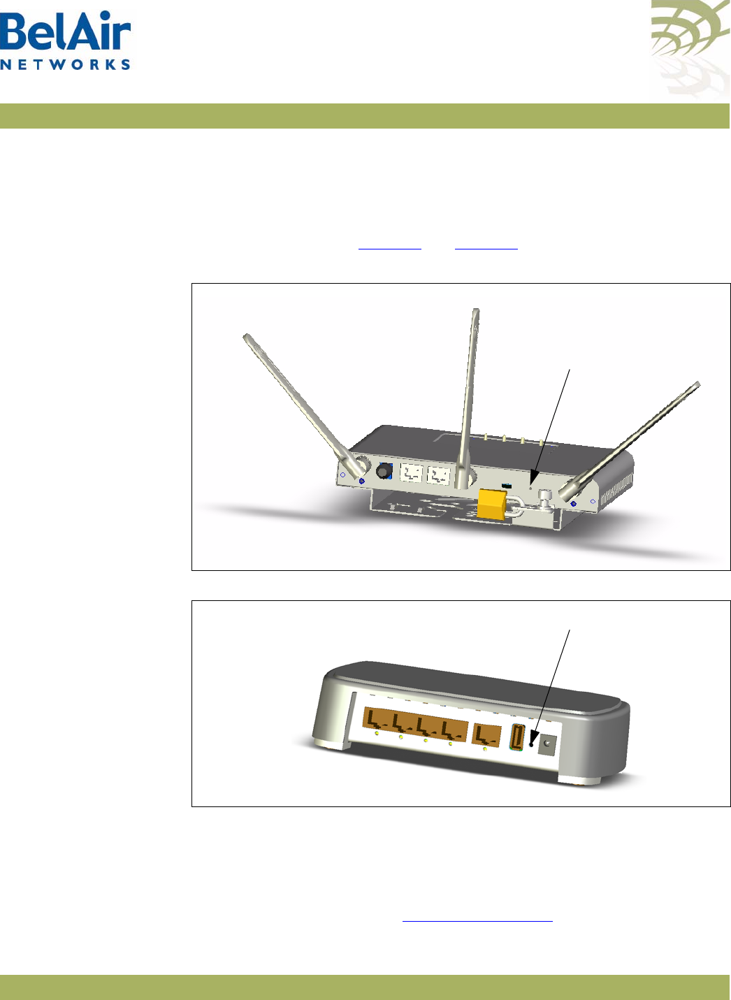
BelAirOS User Guide Resetting to Factory Defaults
April 22, 2012 Confidential Page 340 of 362
Document Number BDTM00000-A02 Draft
BelAir20, BelAir100i
WCS and BelAir20E To reset the AP configuration to factory defaults, do the following steps:
1 Access the AP rear panel. You may need to detach it from its mounting
bracket.
2 With a pen tip or paperclip, gently press the AP’s reset button for more than
15 seconds. Refer to Figure 32 and Figure 33.
Figure 32: BelAir20 and BelAir100i WCS Rear Panel with Reset Button
Figure 33: BelAir20E Rear Panel with Reset Button
3 If necessary, re-attach the AP to its mounting bracket.
BelAir100N,
BelAir100SN,
BelAir100SNE and
BelAir2100
To reset the AP configuration to factory defaults, do the following steps:
1 Access the AP connector field:
—For the BelAir100N, see Figure 34 on page 341.
Reset (Hole)
Reset (Hole)
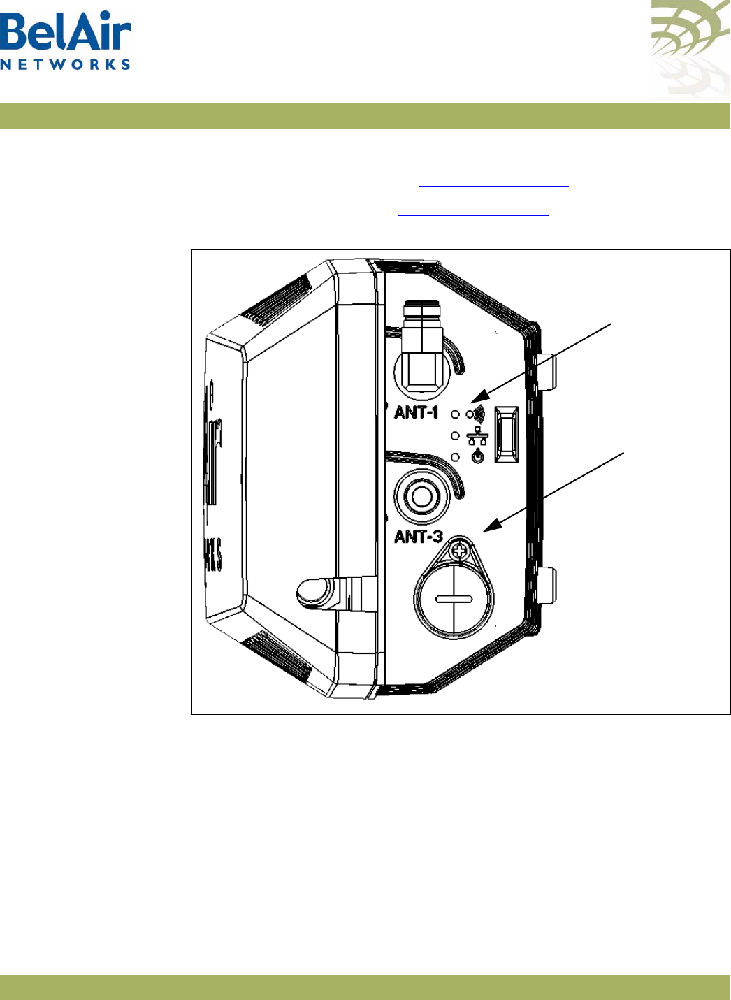
BelAirOS User Guide Resetting to Factory Defaults
April 22, 2012 Confidential Page 341 of 362
Document Number BDTM00000-A02 Draft
—For the BelAir100SN, see Figure 35 on page 342.
—For the BelAir100SNE, see Figure 36 on page 343.
—For the BelAir2100, see Figure 37 on page 344.
Figure 34: BelAir100N Connector Field
Reset Cover
Screw
Power Status
LED
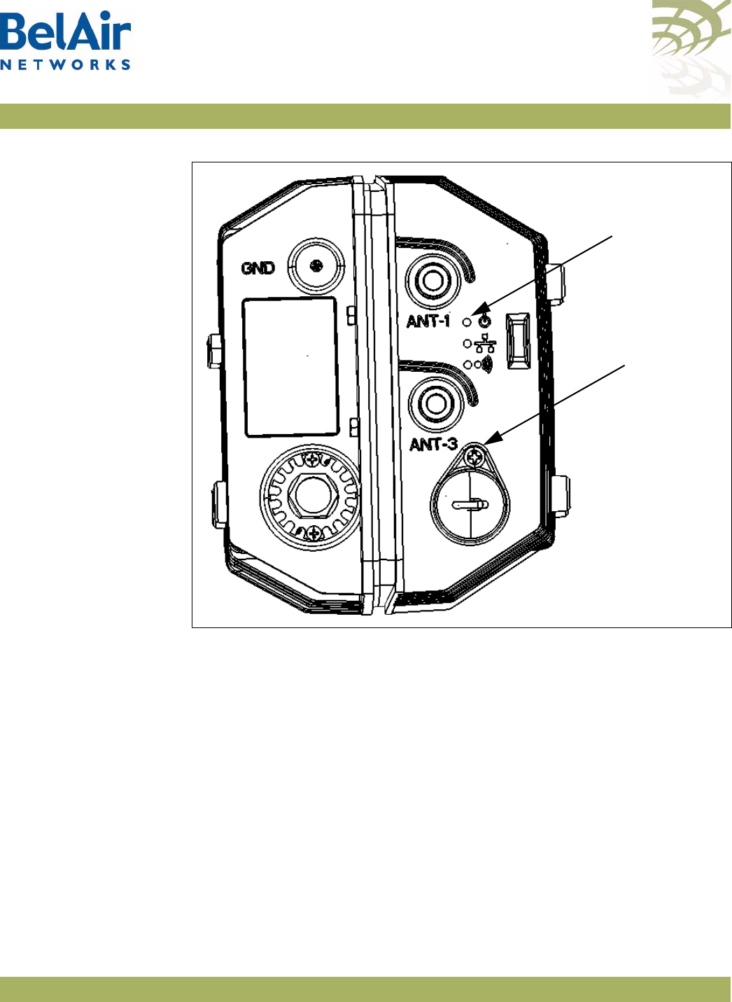
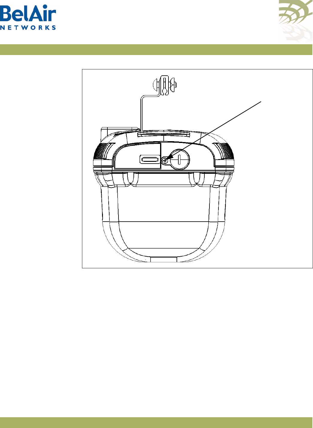
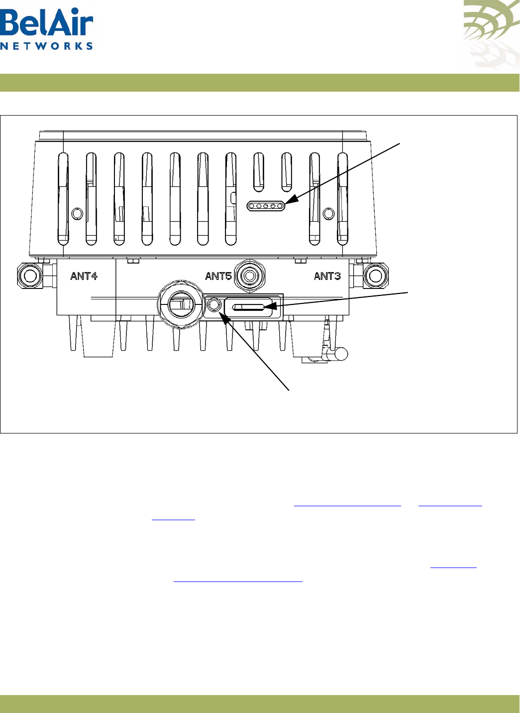
BelAirOS User Guide Resetting to Factory Defaults
April 22, 2012 Confidential Page 344 of 362
Document Number BDTM00000-A02 Draft
Figure 37: BelAir2100 Connector Field
2 Carefully remove the Reset Cover Screw with its gasket and place it in a
secure location.
3 With a pen tip or paperclip, gently press the AP’s reset button for more than
5 seconds. The reset button is located in the hole exposed by removing the
Reset Cover Screw. Refer to Figure 34 on page 341 to Figure 37 on
page 344.
The Power Status LED should become amber once you release the reset
button, indicating that the AP is initializing.
Note: The complete LED start up sequence is described in “AP LED
Descriptions” on page 280.
4 Reinstall the Reset Cover Screw and its gasket. Make sure you tighten the
screw enough so that the gaskets forms a watertight seal over the reset
button access hole.
Reset Cover
Screw
Status LEDs for
BTS card
Status LEDs for
DRUE card

BelAirOS User Guide Detailed Table of Contents
April 22, 2012 Confidential Page 345 of 362
Document Number BDTM00000-A02 Draft
Detailed Table of Contents
About This Document . . . . . . . . . . . . . . . . . . . . . . . . . . . . . . . . . . 4
Typographical Conventions . . . . . . . . . . . . . . . . . . . . . . . . . . . . . . . . . .4
Related Documentation . . . . . . . . . . . . . . . . . . . . . . . . . . . . . . . . . . . . .4
System Overview of BelAir Networks APs . . . . . . . . . . . . . . . . . . 5
BelAir20 . . . . . . . . . . . . . . . . . . . . . . . . . . . . . . . . . . . . . . . . . . . . . . . . .5
BelAir20 Hardware Description . . . . . . . . . . . . . . . . . . . . . . . .5
BelAir20 Antenna Connectivity . . . . . . . . . . . . . . . . . . . . . . . . .7
BelAir100i WCS . . . . . . . . . . . . . . . . . . . . . . . . . . . . . . . . . . . . . . . . . . .7
BelAir100i WCS Hardware Description . . . . . . . . . . . . . . . . . .7
BelAir100i WCS Antenna Connectivity . . . . . . . . . . . . . . . . . .9
BelAir20E . . . . . . . . . . . . . . . . . . . . . . . . . . . . . . . . . . . . . . . . . . . . . . . .9
BelAir20E Hardware Description . . . . . . . . . . . . . . . . . . . . . .10
BelAir20EO . . . . . . . . . . . . . . . . . . . . . . . . . . . . . . . . . . . . . . . . . . . . . .11
BelAir20EO Hardware Description . . . . . . . . . . . . . . . . . . . . .11
BelAir100N . . . . . . . . . . . . . . . . . . . . . . . . . . . . . . . . . . . . . . . . . . . . . .12
BelAir100N Hardware Description . . . . . . . . . . . . . . . . . . . . .13
BelAir100SN . . . . . . . . . . . . . . . . . . . . . . . . . . . . . . . . . . . . . . . . . . . . .14
BelAir100SN Hardware Description . . . . . . . . . . . . . . . . . . . .15
BelAir100SNE . . . . . . . . . . . . . . . . . . . . . . . . . . . . . . . . . . . . . . . . . . . .16
BelAir100SNE Hardware Description . . . . . . . . . . . . . . . . . . .17
BelAir2100 . . . . . . . . . . . . . . . . . . . . . . . . . . . . . . . . . . . . . . . . . . . . . .18
BelAir2100 Hardware Description . . . . . . . . . . . . . . . . . . . . .19
AP Configuration Interfaces . . . . . . . . . . . . . . . . . . . . . . . . . . . . . 21
Command Line Interface . . . . . . . . . . . . . . . . . . . . . . . . . . . . . . . . . . .21
SNMP Interface . . . . . . . . . . . . . . . . . . . . . . . . . . . . . . . . . . . . . . . . . . .21
Integrating the AP with a Pre-deployed NMS . . . . . . . . . . . . .22
Web Interface . . . . . . . . . . . . . . . . . . . . . . . . . . . . . . . . . . . . . . . . . . . .24
Accessing the Web Interface . . . . . . . . . . . . . . . . . . . . . . . . . .24
Accessing the System Page with Secure HTTP or with HTTP 24
Stopping a Session . . . . . . . . . . . . . . . . . . . . . . . . . . . . . . . . . .26

BelAirOS User Guide Detailed Table of Contents
April 22, 2012 Confidential Page 346 of 362
Document Number BDTM00000-A02 Draft
Additional Troubleshooting Tools . . . . . . . . . . . . . . . . . . . . . .26
Command Line Interface Basics . . . . . . . . . . . . . . . . . . . . . . . . . . 27
Connecting to the AP . . . . . . . . . . . . . . . . . . . . . . . . . . . . . . . . . . . . . .27
Starting a CLI Session . . . . . . . . . . . . . . . . . . . . . . . . . . . . . . . . . . . . . .28
Command Modes . . . . . . . . . . . . . . . . . . . . . . . . . . . . . . . . . . . . . . . . .29
Abbreviating Commands . . . . . . . . . . . . . . . . . . . . . . . . . . . . . . . . . . .33
Command History . . . . . . . . . . . . . . . . . . . . . . . . . . . . . . . . . . . . . . . .33
Special CLI Keys . . . . . . . . . . . . . . . . . . . . . . . . . . . . . . . . . . . . . . . . . .34
Help Command . . . . . . . . . . . . . . . . . . . . . . . . . . . . . . . . . . . . . . . . . .34
Saving your Changes . . . . . . . . . . . . . . . . . . . . . . . . . . . . . . . . . . . . . . .37
Saving the Configuration Database . . . . . . . . . . . . . . . . . . . . .37
Restoring the Configuration Database . . . . . . . . . . . . . . . . . .37
Common CLI Commands . . . . . . . . . . . . . . . . . . . . . . . . . . . . . . . . . .38
Terminating your CLI Session . . . . . . . . . . . . . . . . . . . . . . . . .38
Changing Your Password . . . . . . . . . . . . . . . . . . . . . . . . . . . . .38
Clearing the Console Display . . . . . . . . . . . . . . . . . . . . . . . . . .38
Locking the Console Display . . . . . . . . . . . . . . . . . . . . . . . . . .39
Displaying the Current Software Version . . . . . . . . . . . . . . . .39
Displaying the Current Date and Time . . . . . . . . . . . . . . . . . .39
Displaying Current User . . . . . . . . . . . . . . . . . . . . . . . . . . . . .39
Switching User Accounts . . . . . . . . . . . . . . . . . . . . . . . . . . . . .39
Replacing a Token by a String . . . . . . . . . . . . . . . . . . . . . . . . .40
Pinging a Host or Switch . . . . . . . . . . . . . . . . . . . . . . . . . . . . .40
Starting a Telnet Session . . . . . . . . . . . . . . . . . . . . . . . . . . . . .40
Radio Configuration Summary . . . . . . . . . . . . . . . . . . . . . . . . .40
AP Access Methods . . . . . . . . . . . . . . . . . . . . . . . . . . . . . . . . . . . 42
SNMP Configuration Guidelines . . . . . . . . . . . . . . . . . . . . . . . . . . . . .42
SNMPv1/v2 Servers . . . . . . . . . . . . . . . . . . . . . . . . . . . . . . . . .42
SNMPv3 Servers . . . . . . . . . . . . . . . . . . . . . . . . . . . . . . . . . . . .42
SNMP Naming Restrictions . . . . . . . . . . . . . . . . . . . . . . . . . . .43
SNMP Command Reference . . . . . . . . . . . . . . . . . . . . . . . . . . . . . . . .43
SNMP Agent . . . . . . . . . . . . . . . . . . . . . . . . . . . . . . . . . . . . . . .43
SNMP Configuration . . . . . . . . . . . . . . . . . . . . . . . . . . . . . . . .43

BelAirOS User Guide Detailed Table of Contents
April 22, 2012 Confidential Page 347 of 362
Document Number BDTM00000-A02 Draft
Communities . . . . . . . . . . . . . . . . . . . . . . . . . . . . . . . . . . . . . .44
Traps . . . . . . . . . . . . . . . . . . . . . . . . . . . . . . . . . . . . . . . . . . . . .45
Users . . . . . . . . . . . . . . . . . . . . . . . . . . . . . . . . . . . . . . . . . . . . .45
Notifications . . . . . . . . . . . . . . . . . . . . . . . . . . . . . . . . . . . . . . .46
Authentication Traps . . . . . . . . . . . . . . . . . . . . . . . . . . . . . . . .47
Engine Identifier . . . . . . . . . . . . . . . . . . . . . . . . . . . . . . . . . . . .47
SNMP Statistics . . . . . . . . . . . . . . . . . . . . . . . . . . . . . . . . . . . . .47
Telnet . . . . . . . . . . . . . . . . . . . . . . . . . . . . . . . . . . . . . . . . . . . . . . . . . .48
HTTP . . . . . . . . . . . . . . . . . . . . . . . . . . . . . . . . . . . . . . . . . . . . . . . . . .48
Secure HTTP . . . . . . . . . . . . . . . . . . . . . . . . . . . . . . . . . . . . . . . . . . . .48
SSH . . . . . . . . . . . . . . . . . . . . . . . . . . . . . . . . . . . . . . . . . . . . . . . . . . . .48
SSH Access . . . . . . . . . . . . . . . . . . . . . . . . . . . . . . . . . . . . . . . .48
SSL . . . . . . . . . . . . . . . . . . . . . . . . . . . . . . . . . . . . . . . . . . . . . . . . . . . . .48
Displaying Server Certificate . . . . . . . . . . . . . . . . . . . . . . . . . .48
Configuring the Server Certificate . . . . . . . . . . . . . . . . . . . . . .49
Creating RSA Key Pair . . . . . . . . . . . . . . . . . . . . . . . . . . . . . . .49
Creating Certificate Request . . . . . . . . . . . . . . . . . . . . . . . . . .49
Configuring the Server Certificate . . . . . . . . . . . . . . . . . . . . . .49
Saving an SSL Configuration . . . . . . . . . . . . . . . . . . . . . . . . . . .49
TR-069 . . . . . . . . . . . . . . . . . . . . . . . . . . . . . . . . . . . . . . . . . . . . . . . . .50
Configuring ACS Communications . . . . . . . . . . . . . . . . . . . . .50
User and Session Administration . . . . . . . . . . . . . . . . . . . . . . . . . 52
User Privilege Levels . . . . . . . . . . . . . . . . . . . . . . . . . . . . . . . . . . . . . . .52
User Accounts . . . . . . . . . . . . . . . . . . . . . . . . . . . . . . . . . . . . . . . . . . .55
Configuring Authentication for User Accounts . . . . . . . . . . . . . . . . . .56
Authentication Mode . . . . . . . . . . . . . . . . . . . . . . . . . . . . . . . .56
RADIUS Servers . . . . . . . . . . . . . . . . . . . . . . . . . . . . . . . . . . . .57
CLI and Web Sessions . . . . . . . . . . . . . . . . . . . . . . . . . . . . . . . . . . . . .58
Session Management . . . . . . . . . . . . . . . . . . . . . . . . . . . . . . . . .58
Configuring the Session Timeout Interval . . . . . . . . . . . . . . . .59
CLI Prompt Customization . . . . . . . . . . . . . . . . . . . . . . . . . . .59
IP Settings . . . . . . . . . . . . . . . . . . . . . . . . . . . . . . . . . . . . . . . . . . . 61
Displaying IP Parameters . . . . . . . . . . . . . . . . . . . . . . . . . . . . . . . . . . .61

BelAirOS User Guide Detailed Table of Contents
April 22, 2012 Confidential Page 348 of 362
Document Number BDTM00000-A02 Draft
Configuring IP Parameters . . . . . . . . . . . . . . . . . . . . . . . . . . . . . . . . . .62
Configuring Dynamic IP Addressing . . . . . . . . . . . . . . . . . . . . .62
Renewing the IP Address . . . . . . . . . . . . . . . . . . . . . . . . . . . . .63
Auto-IP . . . . . . . . . . . . . . . . . . . . . . . . . . . . . . . . . . . . . . . . . . .63
Setting a Static IP Address and Subnet Mask . . . . . . . . . . . . . .64
Static IP Routes . . . . . . . . . . . . . . . . . . . . . . . . . . . . . . . . . . . . .64
Configuring the Domain Name System Lookup Service . . . . . . . . . . .65
Configuring IP Address Notification . . . . . . . . . . . . . . . . . . . . . . . . . .65
System Settings . . . . . . . . . . . . . . . . . . . . . . . . . . . . . . . . . . . . . . . 66
Country of Operation . . . . . . . . . . . . . . . . . . . . . . . . . . . . . . . . . . . . .66
System Identification Parameters . . . . . . . . . . . . . . . . . . . . . . . . . . . . .67
Custom Fields . . . . . . . . . . . . . . . . . . . . . . . . . . . . . . . . . . . . . . . . . . . .67
Configuring the System Date and Time . . . . . . . . . . . . . . . . . . . . . . . .68
Manual Date and Time Configuration . . . . . . . . . . . . . . . . . . .68
Managing an SNTP Server . . . . . . . . . . . . . . . . . . . . . . . . . . . .69
GPS Coordinates . . . . . . . . . . . . . . . . . . . . . . . . . . . . . . . . . . . . . . . . .70
LED Control . . . . . . . . . . . . . . . . . . . . . . . . . . . . . . . . . . . . . . . . . . . . .72
Find Me Function . . . . . . . . . . . . . . . . . . . . . . . . . . . . . . . . . . .72
LED Enable or Disable . . . . . . . . . . . . . . . . . . . . . . . . . . . . . . .72
Setting the Network Egress Point . . . . . . . . . . . . . . . . . . . . . . . . . . . .72
Enabling Wi-Fi Band Steering . . . . . . . . . . . . . . . . . . . . . . . . . . . . . . . .73
Limiting Broadcast Packets . . . . . . . . . . . . . . . . . . . . . . . . . . . . . . . . . .73
Limiting DHCP Packets from Clients . . . . . . . . . . . . . . . . . . . . . . . . . .74
Displaying AP Inventory Information . . . . . . . . . . . . . . . . . . . . . . . . . .74
Defining a Maintenance Window . . . . . . . . . . . . . . . . . . . . . . . . . . . . .75
Temperature Display . . . . . . . . . . . . . . . . . . . . . . . . . . . . . . . . . . . . . . .75
Displaying System Up Time . . . . . . . . . . . . . . . . . . . . . . . . . . . . . . . . .76
Displaying the Running Configuration . . . . . . . . . . . . . . . . . . . . . . . . .76
Restarting the AP . . . . . . . . . . . . . . . . . . . . . . . . . . . . . . . . . . . . . . . . .76
Creating and Using Script Files . . . . . . . . . . . . . . . . . . . . . . . . . . . . . . .76
Enabling or Disabling Session Logging . . . . . . . . . . . . . . . . . . . . . . . . .77
Local and Remote Configuration . . . . . . . . . . . . . . . . . . . . . . . . . . . . .77
AP Auto-configuration . . . . . . . . . . . . . . . . . . . . . . . . . . . . . . . . . 78

BelAirOS User Guide Detailed Table of Contents
April 22, 2012 Confidential Page 349 of 362
Document Number BDTM00000-A02 Draft
DHCP Options . . . . . . . . . . . . . . . . . . . . . . . . . . . . . . . . . . . . . . . . . . .78
Pre-requisites . . . . . . . . . . . . . . . . . . . . . . . . . . . . . . . . . . . . . .80
Configuring and Using DHCP Options . . . . . . . . . . . . . . . . . .80
Accepting Specific DHCP Parameters . . . . . . . . . . . . . . . . . . .80
DNS . . . . . . . . . . . . . . . . . . . . . . . . . . . . . . . . . . . . . . . . . . . . . . . . . . .81
Configuration Download Profile . . . . . . . . . . . . . . . . . . . . . . . . . . . . .82
Pre-requisites . . . . . . . . . . . . . . . . . . . . . . . . . . . . . . . . . . . . . .82
Using a Configuration Download Profile . . . . . . . . . . . . . . . . .82
Card Settings. . . . . . . . . . . . . . . . . . . . . . . . . . . . . . . . . . . . . . . . . 84
Determining which Cards are in an AP . . . . . . . . . . . . . . . . . . . . . . . .85
Displaying Card Information . . . . . . . . . . . . . . . . . . . . . . . . . . . . . . . . .86
Displaying the Card Physical Data . . . . . . . . . . . . . . . . . . . . . .86
Displaying the Card Physical Interfaces . . . . . . . . . . . . . . . . . .87
Displaying the Card CPU and Memory Usage . . . . . . . . . . . . .87
Card Administrative State . . . . . . . . . . . . . . . . . . . . . . . . . . . . . . . . . .88
Restarting a Card . . . . . . . . . . . . . . . . . . . . . . . . . . . . . . . . . . . . . . . . .88
Card CPU and Memory Performance Monitoring Statistics . . . . . . . .88
BTS Card Commands . . . . . . . . . . . . . . . . . . . . . . . . . . . . . . . . . . . . . .89
Ethernet or LAN Interface Settings . . . . . . . . . . . . . . . . . . . . . . . 91
Managing the Ethernet or LAN Interface Settings . . . . . . . . . . . . . . . .91
Managing Egress AP Traffic . . . . . . . . . . . . . . . . . . . . . . . . . . . . . . . . . .92
VLAN Conversion . . . . . . . . . . . . . . . . . . . . . . . . . . . . . . . . . .92
VLAN Filtering . . . . . . . . . . . . . . . . . . . . . . . . . . . . . . . . . . . . .93
Changing Ethernet or LAN Interface Admin State . . . . . . . . . . . . . . .93
Ethernet or LAN Port Statistics . . . . . . . . . . . . . . . . . . . . . . . . . . . . . .94
Ethernet or LAN Port Performance Monitoring Statistics . . . . . . . . .94
Cable Modem Configuration . . . . . . . . . . . . . . . . . . . . . . . . . . . . 96
Displaying the Cable Modem Information . . . . . . . . . . . . . . . . . . . . . .96
Displaying the Cable Modem Configuration . . . . . . . . . . . . . . . . . . . .96
Displaying the Cable Modem Status . . . . . . . . . . . . . . . . . . . . . . . . . . .97
Configuring Attenuation . . . . . . . . . . . . . . . . . . . . . . . . . . . . . . . . . . . .97
Setting the Cable Modem Interface Down Alarm Threshold . . . . . . .98

BelAirOS User Guide Detailed Table of Contents
April 22, 2012 Confidential Page 350 of 362
Document Number BDTM00000-A02 Draft
Rebooting the Cable Modem . . . . . . . . . . . . . . . . . . . . . . . . . . . . . . . .99
Cable Modem Statistics . . . . . . . . . . . . . . . . . . . . . . . . . . . . . . . . . . . .99
Cable Modem Performance Monitoring Statistics . . . . . . . . . . . . . . .100
Wi-Fi Radio Configuration Overview . . . . . . . . . . . . . . . . . . . . 101
Available Wi-Fi Radios . . . . . . . . . . . . . . . . . . . . . . . . . . . . . . . . . . . .101
Configuration Process . . . . . . . . . . . . . . . . . . . . . . . . . . . . . . . . . . . .102
Configuring Wi-Fi Radio Parameters . . . . . . . . . . . . . . . . . . . . . 103
Displaying Wi-Fi Radio Configuration . . . . . . . . . . . . . . . . . . . . . . . .104
Displaying Configuration Options . . . . . . . . . . . . . . . . . . . . . . . . . . .105
Operating Channel . . . . . . . . . . . . . . . . . . . . . . . . . . . . . . . . . . . . . . .105
Antenna Gain . . . . . . . . . . . . . . . . . . . . . . . . . . . . . . . . . . . . . . . . . . .108
Transmit Power Level . . . . . . . . . . . . . . . . . . . . . . . . . . . . . . . . . . . . .110
Link Distance . . . . . . . . . . . . . . . . . . . . . . . . . . . . . . . . . . . . . . . . . . .111
Dynamic Frequency Selection . . . . . . . . . . . . . . . . . . . . . . . . . . . . . .111
Collision Aware Rate Adaptation . . . . . . . . . . . . . . . . . . . . . . . . . . . .112
WCS Duty Cycle Control . . . . . . . . . . . . . . . . . . . . . . . . . . . . . . . . .112
Rate Aware Fairness . . . . . . . . . . . . . . . . . . . . . . . . . . . . . . . . . . . . . .112
Enhanced Throughput . . . . . . . . . . . . . . . . . . . . . . . . . . . . . . . . . . . .112
802.11n Aggregation . . . . . . . . . . . . . . . . . . . . . . . . . . . . . . . . . . . . . .113
Minimum Association Thresholds . . . . . . . . . . . . . . . . . . . . . . . . . . .113
Doing an RF Survey . . . . . . . . . . . . . . . . . . . . . . . . . . . . . . . . . . . . . .113
AP RF Survey . . . . . . . . . . . . . . . . . . . . . . . . . . . . . . . . . . . . .114
Backhaul RF Survey . . . . . . . . . . . . . . . . . . . . . . . . . . . . . . . .115
All RF Survey . . . . . . . . . . . . . . . . . . . . . . . . . . . . . . . . . . . . .117
Filtering the Output . . . . . . . . . . . . . . . . . . . . . . . . . . . . . . . .117
Sorting the Output . . . . . . . . . . . . . . . . . . . . . . . . . . . . . . . . .117
Changing Wi-Fi Interface Admin State . . . . . . . . . . . . . . . . . . . . . . . .117
Wi-Fi Interface Statistics . . . . . . . . . . . . . . . . . . . . . . . . . . . . . . . . . .117
Wi-Fi Performance Monitoring Statistics . . . . . . . . . . . . . . . . . . . . . .118
Configuring Wi-Fi Access Point Parameters . . . . . . . . . . . . . . . 123
Displaying AP Configuration . . . . . . . . . . . . . . . . . . . . . . . . . . . . . . . .124
AP Custom Rates . . . . . . . . . . . . . . . . . . . . . . . . . . . . . . . . . . . . . . . .124

BelAirOS User Guide Detailed Table of Contents
April 22, 2012 Confidential Page 351 of 362
Document Number BDTM00000-A02 Draft
Displaying Associated Wireless Clients . . . . . . . . . . . . . . . . . . . . . . .126
Displaying Wireless Client Details . . . . . . . . . . . . . . . . . . . . . . . . . . .128
Disconnecting a Wireless Client . . . . . . . . . . . . . . . . . . . . . . . . . . . .128
Wireless Client Load Balancing . . . . . . . . . . . . . . . . . . . . . . . . . . . . .129
Configuring RTS-CTS Handshaking . . . . . . . . . . . . . . . . . . . . . . . . . .129
Specifying the Beacon Period . . . . . . . . . . . . . . . . . . . . . . . . . . . . . . .129
Displaying Client Association Records . . . . . . . . . . . . . . . . . . . . . . .130
Changing AP Admin State . . . . . . . . . . . . . . . . . . . . . . . . . . . . . . . . .131
AP Service Set Identifiers . . . . . . . . . . . . . . . . . . . . . . . . . . . . . . . . . .131
Displaying the SSID Table . . . . . . . . . . . . . . . . . . . . . . . . . . .132
Displaying SSID Details . . . . . . . . . . . . . . . . . . . . . . . . . . . . . .133
Default Management SSID . . . . . . . . . . . . . . . . . . . . . . . . . . .133
Configuring SSIDs . . . . . . . . . . . . . . . . . . . . . . . . . . . . . . . . . .134
Upstream User Priority Marking . . . . . . . . . . . . . . . . . . . . . .136
Setting Traffic Limits . . . . . . . . . . . . . . . . . . . . . . . . . . . . . . . .136
Limiting the Number of Clients per SSID . . . . . . . . . . . . . . .136
Providing Vendor Specific Information . . . . . . . . . . . . . . . . .137
Changing SSID Admin State . . . . . . . . . . . . . . . . . . . . . . . . . .139
Wi-Fi SSID Performance Monitoring Statistics . . . . . . . . . . .139
Out-of-service Advertising . . . . . . . . . . . . . . . . . . . . . . . . . . . . . . . . .140
Filtering Broadcast and Multicast Packets . . . . . . . . . . . . . . . . . . . . .141
Broadcast to Unicast Packet Conversion . . . . . . . . . . . . . . . . . . . . . .142
ARP Filtering . . . . . . . . . . . . . . . . . . . . . . . . . . . . . . . . . . . . . . . . . . . .143
ARP to Unicast Conversion . . . . . . . . . . . . . . . . . . . . . . . . . . . . . . . .143
802.11b Protection . . . . . . . . . . . . . . . . . . . . . . . . . . . . . . . . . . . . . . .144
Wi-Fi Client Statistics . . . . . . . . . . . . . . . . . . . . . . . . . . . . . . . . . . . . .144
Wi-Fi AP Security . . . . . . . . . . . . . . . . . . . . . . . . . . . . . . . . . . . . 146
Security Options for Wireless Clients . . . . . . . . . . . . . . . . . . . . . . . .146
RADIUS Servers for Wireless Clients . . . . . . . . . . . . . . . . . . . . . . . .148
Managing RADIUS Servers . . . . . . . . . . . . . . . . . . . . . . . . . . .150
Changing RADIUS Server Admin State . . . . . . . . . . . . . . . . .151
Assigning SSIDs to RADIUS Servers . . . . . . . . . . . . . . . . . . .151
RADIUS Pre-authentication . . . . . . . . . . . . . . . . . . . . . . . . . .151
RADIUS Assigned VLAN . . . . . . . . . . . . . . . . . . . . . . . . . . . .152

BelAirOS User Guide Detailed Table of Contents
April 22, 2012 Confidential Page 352 of 362
Document Number BDTM00000-A02 Draft
RADIUS Accounting . . . . . . . . . . . . . . . . . . . . . . . . . . . . . . . .153
Client Authentication and De-authentication Trap . . . . . . . . . . . . . .153
AP Privacy . . . . . . . . . . . . . . . . . . . . . . . . . . . . . . . . . . . . . . . . . . . . . .153
Wireless Client Blacklist . . . . . . . . . . . . . . . . . . . . . . . . . . . . . . . . . . .155
Wireless Client Access Control List . . . . . . . . . . . . . . . . . . . . . . . . .155
Controlling Inter-client Communication . . . . . . . . . . . . . . . . . . . . . .156
Determining the MAC Address of the Internet gateway . . .157
Disabling or Enabling AP Wireless Bridging . . . . . . . . . . . . . .157
Disabling Inter-AP Wireless Client Communication . . . . . . .158
Secure MAC White List . . . . . . . . . . . . . . . . . . . . . . . . . . . . .158
AP Secure Port Mode . . . . . . . . . . . . . . . . . . . . . . . . . . . . . . .159
Auto-secure Gateway . . . . . . . . . . . . . . . . . . . . . . . . . . . . . .159
Protecting against Denial of Service Attacks . . . . . . . . . . . . . . . . . . .159
Deauthentication DoS . . . . . . . . . . . . . . . . . . . . . . . . . . . . . .160
Wi-Fi Backhaul Link Configuration . . . . . . . . . . . . . . . . . . . . . . 161
Displaying Backhaul Link Configuration . . . . . . . . . . . . . . . . . . . . . . .161
Configuring Backhaul Link Identifier, Topology and Privacy . . . . . . .162
Managing MP-to-MP Meshes . . . . . . . . . . . . . . . . . . . . . . . . . . . . . . .164
Displaying the Mesh Topology . . . . . . . . . . . . . . . . . . . . . . . .164
Setting a Link RSSI Threshold . . . . . . . . . . . . . . . . . . . . . . . .165
Managing the Mesh Blacklist . . . . . . . . . . . . . . . . . . . . . . . . . .166
Mesh Auto-connections . . . . . . . . . . . . . . . . . . . . . . . . . . . . .166
Managing Mesh Auto-connections . . . . . . . . . . . . . . . . . . . . .167
Egress Protection . . . . . . . . . . . . . . . . . . . . . . . . . . . . . . . . . . . . . . . .168
Changing Backhaul Link Admin State . . . . . . . . . . . . . . . . . . . . . . . . .168
Mobile Backhaul Mesh . . . . . . . . . . . . . . . . . . . . . . . . . . . . . . . . 169
Configuring Mobile Backhaul Mesh Links . . . . . . . . . . . . . . . . . . . . . .170
Displaying Mobility Configuration and Status . . . . . . . . . . . .170
Configuring MIMO Operation for Mobile Applications . . . .171
Configuring and Enabling Mobile Backhaul Mesh Links . . . . .171
Mobile Backhaul Point-to-point Links . . . . . . . . . . . . . . . . . . . . 173
Scanning Process . . . . . . . . . . . . . . . . . . . . . . . . . . . . . . . . . . . . . . . . .174

BelAirOS User Guide Detailed Table of Contents
April 22, 2012 Confidential Page 353 of 362
Document Number BDTM00000-A02 Draft
Sample Subscriber Station Configuration . . . . . . . . . . . . . . . . . . . . .174
Sample Base Station Configuration . . . . . . . . . . . . . . . . . . . . . . . . . .176
Mobile Backhaul Point-to-point Commands . . . . . . . . . . . . . . . . . . .178
Displaying Mobile Backhaul Point-to-point Configuration . .178
Displaying Link Status . . . . . . . . . . . . . . . . . . . . . . . . . . . . . . .178
Displaying Scan Results . . . . . . . . . . . . . . . . . . . . . . . . . . . . . .179
Managing Interfaces . . . . . . . . . . . . . . . . . . . . . . . . . . . . . . . .179
Managing the Scan List . . . . . . . . . . . . . . . . . . . . . . . . . . . . . .180
Associating a Scan List to an Interface . . . . . . . . . . . . . . . . . .180
Configuring RSSI Threshold . . . . . . . . . . . . . . . . . . . . . . . . . .180
Primary Link Drop . . . . . . . . . . . . . . . . . . . . . . . . . . . . . . . . .181
Mobile Link Identifier . . . . . . . . . . . . . . . . . . . . . . . . . . . . . . .181
Home Check . . . . . . . . . . . . . . . . . . . . . . . . . . . . . . . . . . . . .181
Base Station Out-of-service Check . . . . . . . . . . . . . . . . . . . .181
Release 7 Compatibility . . . . . . . . . . . . . . . . . . . . . . . . . . . . .182
Single Channel Mesh . . . . . . . . . . . . . . . . . . . . . . . . . . . . . . . .182
Operating in High Capacity and Interference Environments. . . 184
Modulation Rate Control . . . . . . . . . . . . . . . . . . . . . . . . . . . . . . . . . .185
VLAN based QOS . . . . . . . . . . . . . . . . . . . . . . . . . . . . . . . . . . . . . . .185
Traffic Priority Based on Modulation Rate . . . . . . . . . . . . . . . . . . . . .186
No SSID on Egress Down . . . . . . . . . . . . . . . . . . . . . . . . . . . . . . . . .186
Ethernet Port Statistics . . . . . . . . . . . . . . . . . . . . . . . . . . . . . . . . . . . .186
Access Receive and Transmit Error Statistics with SNMP Support .187
Noise Floor Support . . . . . . . . . . . . . . . . . . . . . . . . . . . . . . . . . . . . .187
Access Packet RSSI Filter . . . . . . . . . . . . . . . . . . . . . . . . . . . . . . . . . .187
Effective Mesh Path Selection . . . . . . . . . . . . . . . . . . . . . . . . . . . . . . .187
Blacklist SNMP Support . . . . . . . . . . . . . . . . . . . . . . . . . . . . . . . . . . .188
Client Association Records . . . . . . . . . . . . . . . . . . . . . . . . . . . . . . . .188
CTS-to-Self Control . . . . . . . . . . . . . . . . . . . . . . . . . . . . . . . . . . . . . .188
DHCP to Attached Clients Only . . . . . . . . . . . . . . . . . . . . . . . . . . . .188
ARP to Attached Clients Only . . . . . . . . . . . . . . . . . . . . . . . . . . . . . .188
Upstream Broadcast Filter . . . . . . . . . . . . . . . . . . . . . . . . . . . . . . . . .188
Secure Port Mode . . . . . . . . . . . . . . . . . . . . . . . . . . . . . . . . . . . . . . . .189
Wireless Bridging . . . . . . . . . . . . . . . . . . . . . . . . . . . . . . . . . . . . . . . .189

BelAirOS User Guide Detailed Table of Contents
April 22, 2012 Confidential Page 354 of 362
Document Number BDTM00000-A02 Draft
Client Load Balancing . . . . . . . . . . . . . . . . . . . . . . . . . . . . . . . . . . . . .189
Client Authentication History . . . . . . . . . . . . . . . . . . . . . . . . . . . . . .190
Automatic Mesh Connect . . . . . . . . . . . . . . . . . . . . . . . . . . . . . . . . .190
Traffic Test Tool . . . . . . . . . . . . . . . . . . . . . . . . . . . . . . . . . . . . . . . . .190
DHCP Relay Settings . . . . . . . . . . . . . . . . . . . . . . . . . . . . . . . . . 191
Displaying the DHCP Relay Configuration . . . . . . . . . . . . . . . . . . . .191
Modifying DHCP Relay Parameters . . . . . . . . . . . . . . . . . . . . . . . . . .192
Interface Administrative State . . . . . . . . . . . . . . . . . . . . . . . . . . . . . .193
Assigning SSID Traffic to Use DHCP Relay . . . . . . . . . . . . . . . . . . . .193
DHCP Address Filtering . . . . . . . . . . . . . . . . . . . . . . . . . . . . . . . . . . .193
DHCP Relay Performance Monitoring Statistics . . . . . . . . . . . . . . . .194
Network Address Translation . . . . . . . . . . . . . . . . . . . . . . . . . . 196
Displaying the Operational Status . . . . . . . . . . . . . . . . . . . . . . . . . . .197
Displaying the Current DHCP Lease Status . . . . . . . . . . . . . . . . . . .197
Displaying the DHCP Lease History . . . . . . . . . . . . . . . . . . . . . . . . .197
Configuring Network Address Translation . . . . . . . . . . . . . . . . . . . .198
Choosing an Egress Interface . . . . . . . . . . . . . . . . . . . . . . . . . . . . . . .198
Preventing AP Management from within the Scope . . . . . . . . . . . . .199
Enabling or Disabling Individual Scopes . . . . . . . . . . . . . . . . . . . . . . .199
Changing NAT Admin State . . . . . . . . . . . . . . . . . . . . . . . . . . . . . . . .199
Managing APs in a NAT Cluster . . . . . . . . . . . . . . . . . . . . . . . . . . . . .199
Mac Address to IP Address Mapping . . . . . . . . . . . . . . . . . . .199
Port Forwarding . . . . . . . . . . . . . . . . . . . . . . . . . . . . . . . . . . .200
Universal Access Method . . . . . . . . . . . . . . . . . . . . . . . . . . . . . . 201
Displaying the Current Configuration . . . . . . . . . . . . . . . . . . . . . . . .203
Displaying the Operational Status . . . . . . . . . . . . . . . . . . . . . . . . . . .203
Displaying the Client Session Information . . . . . . . . . . . . . . . . . . . . .204
Specifying the Web Server . . . . . . . . . . . . . . . . . . . . . . . . . . . . . . . . .205
Specifying Redirection Variable Pairs . . . . . . . . . . . . . . . . . . . . . . . . .206
Specifying the RADIUS Server . . . . . . . . . . . . . . . . . . . . . . . . . . . . . .206
Managing White List Entries . . . . . . . . . . . . . . . . . . . . . . . . . . . . . . . .206
Associating VLAN Traffic to a Scope . . . . . . . . . . . . . . . . . . . . . . . . .207

BelAirOS User Guide Detailed Table of Contents
April 22, 2012 Confidential Page 355 of 362
Document Number BDTM00000-A02 Draft
Performing MAC Address Authentication . . . . . . . . . . . . . . . . . . . . .207
Collecting Accounting Information . . . . . . . . . . . . . . . . . . . . . . . . . .208
Operating in WAN Mode . . . . . . . . . . . . . . . . . . . . . . . . . . . . . . . . .209
Changing UAM Admin State . . . . . . . . . . . . . . . . . . . . . . . . . . . . . . . .209
Using Layer 2 Tunnels . . . . . . . . . . . . . . . . . . . . . . . . . . . . . . . . 210
Configuring the AP for Layer 2 Tunneling . . . . . . . . . . . . . . . . . . . . .211
Displaying Tunnel Configuration and Status . . . . . . . . . . . . .212
Starting and Stopping Layer 2 Tunneling . . . . . . . . . . . . . . . .213
Configuring Layer 2 Tunnels . . . . . . . . . . . . . . . . . . . . . . . . .214
Setting Tunnel Engine Parameters . . . . . . . . . . . . . . . . . . . . .214
Configuring Tunnel Advanced Parameters . . . . . . . . . . . . . .215
Enabling Backhaul Protection for Tunnels . . . . . . . . . . . . . . .216
Bandwidth Limits . . . . . . . . . . . . . . . . . . . . . . . . . . . . . . . . . .216
Configuring Tunnels for the RedBack SmartEdge Router . . .217
Configuring Tunnels for a Router using GRE . . . . . . . . . . . .219
Configuring Tunnels for PMIP Implementations . . . . . . . . . .220
Mapping User Traffic . . . . . . . . . . . . . . . . . . . . . . . . . . . . . . .221
Configuring Authentication . . . . . . . . . . . . . . . . . . . . . . . . . .222
Configuring a Tunnel Group Name . . . . . . . . . . . . . . . . . . . .222
Relaying Traffic QOS Settings . . . . . . . . . . . . . . . . . . . . . . . .222
Setting the Tunnel Down Alarm Threshold . . . . . . . . . . . . .223
Layer 2 Tunnel Performance Monitoring Statistics . . . . . . . .223
Configuring the Network Central Router for Layer 2 Tunneling . . .224
Quality of Service Settings . . . . . . . . . . . . . . . . . . . . . . . . . . . . . 225
System QoS . . . . . . . . . . . . . . . . . . . . . . . . . . . . . . . . . . . . . . . . . . . .225
Prioritization . . . . . . . . . . . . . . . . . . . . . . . . . . . . . . . . . . . . . .225
Prioritizing Traffic Based on User Priority Bits . . . . . . . . . . .226
Prioritizing Traffic using VLAN IDs . . . . . . . . . . . . . . . . . . . .226
Resetting the QoS Configuration . . . . . . . . . . . . . . . . . . . . . .227
Displaying a Summary of System QoS Settings . . . . . . . . . . .227
Displaying the Prioritization Settings . . . . . . . . . . . . . . . . . . .228
Radio QoS . . . . . . . . . . . . . . . . . . . . . . . . . . . . . . . . . . . . . . . . . . . . . .228
Displaying a Summary of Radio QoS Settings . . . . . . . . . . . .228

BelAirOS User Guide Detailed Table of Contents
April 22, 2012 Confidential Page 356 of 362
Document Number BDTM00000-A02 Draft
Enabling or Disabling Wireless Multi-media . . . . . . . . . . . . .229
QoS Mapping Scheme . . . . . . . . . . . . . . . . . . . . . . . . . . . . . . .229
Unscheduled Automatic Power-save Delivery . . . . . . . . . . .230
Layer 2 Network Configuration. . . . . . . . . . . . . . . . . . . . . . . . . 231
Spanning Tree Protocol Overview . . . . . . . . . . . . . . . . . . . . . . . . . . .231
Configuring Spanning Tree Priority . . . . . . . . . . . . . . . . . . . .232
Configuring Other Spanning Tree Parameters . . . . . . . . . . .233
RSTP Commands . . . . . . . . . . . . . . . . . . . . . . . . . . . . . . . . . . . . . . . .234
Displaying the RSTP Configuration Settings . . . . . . . . . . . . .234
Displaying the RSTP Topology Information . . . . . . . . . . . . . .236
Displaying RSTP Port Roles and States . . . . . . . . . . . . . . . . .239
Configuring the Bridge Aging Time . . . . . . . . . . . . . . . . . . . .240
RSTP Priority . . . . . . . . . . . . . . . . . . . . . . . . . . . . . . . . . . . . .240
RSTP Version . . . . . . . . . . . . . . . . . . . . . . . . . . . . . . . . . . . . .240
Transmit Hold Count . . . . . . . . . . . . . . . . . . . . . . . . . . . . . . .240
Max Age, Hello Time and Forward Delay . . . . . . . . . . . . . . .241
RSTP Link Priority . . . . . . . . . . . . . . . . . . . . . . . . . . . . . . . . .241
RSTP Static Path Cost . . . . . . . . . . . . . . . . . . . . . . . . . . . . . .242
Dynamic Path Cost . . . . . . . . . . . . . . . . . . . . . . . . . . . . . . . . .242
RSTP Protocol Migration on an Interface . . . . . . . . . . . . . . .243
RSTP Edge Port Status . . . . . . . . . . . . . . . . . . . . . . . . . . . . . .243
RSTP Point-To-Point Status of an Interface . . . . . . . . . . . . . .244
Interface RSTP Configuration . . . . . . . . . . . . . . . . . . . . . . . .244
Changing RSTP Admin State . . . . . . . . . . . . . . . . . . . . . . . . .244
RSTP Statistics . . . . . . . . . . . . . . . . . . . . . . . . . . . . . . . . . . . .244
Performing a Software Upgrade. . . . . . . . . . . . . . . . . . . . . . . . . 246
Upgrade Process Overview . . . . . . . . . . . . . . . . . . . . . . . . . . . . . . . .246
Downloading a New Software Load . . . . . . . . . . . . . . . . . . . . . . . . .248
Canceling a Software Upgrade . . . . . . . . . . . . . . . . . . . . . . . . . . . . . .249
Verifying a Successful Download . . . . . . . . . . . . . . . . . . . . . . . . . . . .250
Activating a Software Load . . . . . . . . . . . . . . . . . . . . . . . . . . . . . . . . .250
Committing a New Software Load . . . . . . . . . . . . . . . . . . . . . . . . . .251
Backing Out from a Software Upgrade . . . . . . . . . . . . . . . . . . . . . . .252

BelAirOS User Guide Detailed Table of Contents
April 22, 2012 Confidential Page 357 of 362
Document Number BDTM00000-A02 Draft
Displaying the Status of the Software Upgrade . . . . . . . . . . . . . . . . .253
Clearing the Upgrade Failure Alarm . . . . . . . . . . . . . . . . . . . . . . . . .253
Auto-upgrade . . . . . . . . . . . . . . . . . . . . . . . . . . . . . . . . . . . . . . . . . . .253
Alarm and Event Reporting . . . . . . . . . . . . . . . . . . . . . . . . . . . . 254
Alarm Types and Severity . . . . . . . . . . . . . . . . . . . . . . . . . . . . . . . . . .254
Displaying Active Alarms . . . . . . . . . . . . . . . . . . . . . . . . . . . . . . . . . .255
Displaying the Alarm History . . . . . . . . . . . . . . . . . . . . . . . . . . . . . . .255
Using Syslog . . . . . . . . . . . . . . . . . . . . . . . . . . . . . . . . . . . . . . . . 258
Displaying the Syslog Configuration . . . . . . . . . . . . . . . . . . . . . . . . . .258
Configuring the Syslog Server IP Address . . . . . . . . . . . . . . . . . . . . .259
Sending Syslog Messages to a CLI Session . . . . . . . . . . . . . . . . . . . . .259
Configuring the Log Level . . . . . . . . . . . . . . . . . . . . . . . . . . . . . . . . . .259
Configuring the Hostname Option . . . . . . . . . . . . . . . . . . . . . . . . . .260
Configuring the Keep-alive Interval . . . . . . . . . . . . . . . . . . . . . . . . . .260
Configuring Lawful Intercept Data Retrieval . . . . . . . . . . . . . . . . . . .260
Gathering Additional Troubleshooting Information . . . . . . . . . 262
Determining Service Health Levels . . . . . . . . . . . . . . . . . . . . . . . . . .262
Gathering Hardware Log Files . . . . . . . . . . . . . . . . . . . . . . . . . . . . . .263
TFTP Transfer of Internal Log Files . . . . . . . . . . . . . . . . . . . .263
Troubleshooting Wireless Client Connections. . . . . . . . . . . . . 265
Troubleshooting Client Access . . . . . . . . . . . . . . . . . . . . . . . . . . . . . .265
Troubleshooting Client Association and DHCP . . . . . . . . . . . . . . . .267
Authentication History Log Messages . . . . . . . . . . . . . . . . . . . . . . . .268
Normal Network Events . . . . . . . . . . . . . . . . . . . . . . . . . . . .268
Normal Client Events . . . . . . . . . . . . . . . . . . . . . . . . . . . . . . .269
Network Failure Events . . . . . . . . . . . . . . . . . . . . . . . . . . . . .270
Client Failure Events . . . . . . . . . . . . . . . . . . . . . . . . . . . . . . . .270
Client EAP Failure Events . . . . . . . . . . . . . . . . . . . . . . . . . . . .271
Running Link Diagnostics . . . . . . . . . . . . . . . . . . . . . . . . . . . . . . 273

BelAirOS User Guide Detailed Table of Contents
April 22, 2012 Confidential Page 358 of 362
Document Number BDTM00000-A02 Draft
Path Trace Tool . . . . . . . . . . . . . . . . . . . . . . . . . . . . . . . . . . . . . . . . . .273
Traffic Tool . . . . . . . . . . . . . . . . . . . . . . . . . . . . . . . . . . . . . . . . . . . . .273
Web Radio Troubleshooting Tools . . . . . . . . . . . . . . . . . . . . . . 277
Tool Access . . . . . . . . . . . . . . . . . . . . . . . . . . . . . . . . . . . . . . . . . . . . .277
Throughput Meter . . . . . . . . . . . . . . . . . . . . . . . . . . . . . . . . . . . . . . .277
Histogram . . . . . . . . . . . . . . . . . . . . . . . . . . . . . . . . . . . . . . . . . . . . . .278
Histogram Modes . . . . . . . . . . . . . . . . . . . . . . . . . . . . . . . . . .278
Zoom and Shift Functions . . . . . . . . . . . . . . . . . . . . . . . . . . .278
AP LED Descriptions . . . . . . . . . . . . . . . . . . . . . . . . . . . . . . . . . 280
BelAir20 . . . . . . . . . . . . . . . . . . . . . . . . . . . . . . . . . . . . . . . . . . . . . . .280
BelAir100i WCS . . . . . . . . . . . . . . . . . . . . . . . . . . . . . . . . . . . . . . . . .282
BelAir20E . . . . . . . . . . . . . . . . . . . . . . . . . . . . . . . . . . . . . . . . . . . . . .283
BelAir20EO . . . . . . . . . . . . . . . . . . . . . . . . . . . . . . . . . . . . . . . . . . . . .285
BelAir100N and BelAir2100 . . . . . . . . . . . . . . . . . . . . . . . . . . . . . . . .286
BelAir100N and BelAir2100 Power-up LED Sequence . . . . .287
BelAir100SN and BelAir100SNE . . . . . . . . . . . . . . . . . . . . . . . . . . . .288
BelAir100SN and BelAir100SNE Power-up LED Sequence .290
For More Information. . . . . . . . . . . . . . . . . . . . . . . . . . . . . . . . . 291
Installation Guide . . . . . . . . . . . . . . . . . . . . . . . . . . . . . . . . . . . . . . . .291
BelAir OS User Guide . . . . . . . . . . . . . . . . . . . . . . . . . . . . . . . . . . . .291
Technical Support. . . . . . . . . . . . . . . . . . . . . . . . . . . . . . . . . . . . 293
Support Resources . . . . . . . . . . . . . . . . . . . . . . . . . . . . . . . . . . . . . . .293
Warranty and Limitations . . . . . . . . . . . . . . . . . . . . . . . . . . . . . . . . . .293
Definitions and Acronyms . . . . . . . . . . . . . . . . . . . . . . . . . . . . . 294
Appendix A: AP Configuration Sheets . . . . . . . . . . . . . . . . . . . .296
Appendix B: Mesh Auto-connection Example . . . . . . . . . . . . . . 299
Setup and Initial Conditions . . . . . . . . . . . . . . . . . . . . . . . . . . . . . . . .299
Fault Conditions . . . . . . . . . . . . . . . . . . . . . . . . . . . . . . . . . . . . . . . . .303

BelAirOS User Guide Detailed Table of Contents
April 22, 2012 Confidential Page 359 of 362
Document Number BDTM00000-A02 Draft
Recovery Conditions . . . . . . . . . . . . . . . . . . . . . . . . . . . . . . . . . . . . .306
Appendix C: Scripting Guidelines . . . . . . . . . . . . . . . . . . . . . . . .309
General Scripting Guidelines . . . . . . . . . . . . . . . . . . . . . . . . . . . . . . .309
Overview . . . . . . . . . . . . . . . . . . . . . . . . . . . . . . . . . . . . . . . .309
Creating a BelAirOS Script . . . . . . . . . . . . . . . . . . . . . . . . . .309
Manually Transferring Files to and from an AP . . . . . . . . . . .310
Managing and Manually Running Script Files . . . . . . . . . . . . .311
Specifying Physical Interfaces . . . . . . . . . . . . . . . . . . . . . . . . . . . . . . .312
Physical Interface Declaration Summary . . . . . . . . . . . . . . . .312
Physical Interface Declaration Specifications . . . . . . . . . . . . .312
Physical Interface Script Example - Setup . . . . . . . . . . . . . . .313
Physical Interface Script Example - Script . . . . . . . . . . . . . . .314
Physical Interface Script Example - Output . . . . . . . . . . . . . .314
Including a Reboot Command in a Script . . . . . . . . . . . . . . . . . . . . .316
Reboot Declaration Summary . . . . . . . . . . . . . . . . . . . . . . . .317
Reboot Declaration Specification . . . . . . . . . . . . . . . . . . . . . .317
Reboot Script Example . . . . . . . . . . . . . . . . . . . . . . . . . . . . . .318
Common AP Assembly Codes . . . . . . . . . . . . . . . . . . . . . . . . . . . . . .319
Common Radio Card Descriptions . . . . . . . . . . . . . . . . . . . . . . . . . .320
Sample Universal Auto-configuration Script . . . . . . . . . . . . . . . . . . .322
Appendix D: Alarm and Event Definitions . . . . . . . . . . . . . . . . .325
Appendix E: Resetting to Factory Defaults . . . . . . . . . . . . . . . . . 339
Resetting to Factory Defaults with a CLI Command . . . . . . . . . . . .339
Resetting to Factory Defaults with the Reset Button . . . . . . . . . . . .339
BelAir20, BelAir100i WCS and BelAir20E . . . . . . . . . . . . . . .340
BelAir100N, BelAir100SN, BelAir100SNE and BelAir2100 .340
Detailed Table of Contents . . . . . . . . . . . . . . . . . . . . . . . . . . . . 345
List of Figures
Figure 1: BelAir20 Hardware Module Block Diagram . . . . . . . . . . . . . . . . . . . .6

BelAirOS User Guide Detailed Table of Contents
April 22, 2012 Confidential Page 360 of 362
Document Number BDTM00000-A02 Draft
Figure 2: BelAir100i WCS Hardware Module Block Diagram . . . . . . . . . . . . . .8
Figure 3: BelAir20E Hardware Module Block Diagram . . . . . . . . . . . . . . . . . .10
Figure 4: BelAir20EO Hardware Module Block Diagram. . . . . . . . . . . . . . . . .12
Figure 5: BelAir100N Hardware Module Block Diagram. . . . . . . . . . . . . . . . .14
Figure 6: BelAir100SN Hardware Module Block Diagram . . . . . . . . . . . . . . . .16
Figure 7: BelAir100SNE Hardware Module Block Diagram . . . . . . . . . . . . . . .18
Figure 8: BelAir2100 Hardware Module Block Diagram . . . . . . . . . . . . . . . . .20
Figure 9: Typical Login Page . . . . . . . . . . . . . . . . . . . . . . . . . . . . . . . . . . . . . . .25
Figure 10: Typical Web Interface Main Page . . . . . . . . . . . . . . . . . . . . . . . . . .25
Figure 11: Sample Output of mode Command . . . . . . . . . . . . . . . . . . . . . . . .30
Figure 12: BelAir100SN Connector Fields . . . . . . . . . . . . . . . . . . . . . . . . . . .109
Figure 13: BelAir100N Connector Fields . . . . . . . . . . . . . . . . . . . . . . . . . . .109
Figure 14: Client Record Detail Example . . . . . . . . . . . . . . . . . . . . . . . . . . . .131
Figure 15: Mobile Backhaul Links Connecting Vehicle Cameras to Roadside Net-
work . . . . . . . . . . . . . . . . . . . . . . . . . . . . . . . . . . . . . . . . . . . . . . . . . .169
Figure 16: Wireless Mobility using L2TP. . . . . . . . . . . . . . . . . . . . . . . . . . . . .210
Figure 17: Active and Standby Software Loads . . . . . . . . . . . . . . . . . . . . . . .247
Figure 18: Software Upgrade Step 3 - Downloading the New Software Load . .
249
Figure 19: Software Upgrade Step 7 - Commit the Software Load . . . . . . .251
Figure 20: Backing Out from an Uncommitted Software Upgrade . . . . . . . .252
Figure 21: Sample Network Map for the Example . . . . . . . . . . . . . . . . . . . . .265
Figure 22: Troubleshooting Wireless Client Access . . . . . . . . . . . . . . . . . . .266
Figure 23: Throughput Meter Sample Output . . . . . . . . . . . . . . . . . . . . . . . .278
Figure 24: Histogram Sample Output . . . . . . . . . . . . . . . . . . . . . . . . . . . . . .279
Figure 25: LEDs . . . . . . . . . . . . . . . . . . . . . . . . . . . . . . . . . . . . . . . . . . . . . . . .280
Figure 26: LEDs . . . . . . . . . . . . . . . . . . . . . . . . . . . . . . . . . . . . . . . . . . . . . . . .282
Figure 27: LEDs . . . . . . . . . . . . . . . . . . . . . . . . . . . . . . . . . . . . . . . . . . . . . . .284
Figure 28: LEDs . . . . . . . . . . . . . . . . . . . . . . . . . . . . . . . . . . . . . . . . . . . . . . .285
Figure 29: Auto-connection Initial Conditions . . . . . . . . . . . . . . . . . . . . . . . .299
Figure 30: Auto-connection and Fault Conditions . . . . . . . . . . . . . . . . . . . . .304
Figure 31: Auto-connection after Recovery before Revert . . . . . . . . . . . . . .308
Figure 32: BelAir20 and BelAir100i WCS Rear Panel with Reset Button . .340
Figure 33: BelAir20E Rear Panel with Reset Button . . . . . . . . . . . . . . . . . . .340
Figure 34: BelAir100N Connector Field . . . . . . . . . . . . . . . . . . . . . . . . . . . .341
Figure 35: BelAir100SN Connector Field . . . . . . . . . . . . . . . . . . . . . . . . . . .342
Figure 36: BelAir100SNE Connector Field . . . . . . . . . . . . . . . . . . . . . . . . . .343
Figure 37: BelAir2100 Connector Field . . . . . . . . . . . . . . . . . . . . . . . . . . . . .344

BelAirOS User Guide Detailed Table of Contents
April 22, 2012 Confidential Page 361 of 362
Document Number BDTM00000-A02 Draft
List of Tables
Table 1: Product Name Synonyms . . . . . . . . . . . . . . . . . . . . . . . . . . . . . . . . . . .4
Table 2: BelAir20 Antenna Connectivity . . . . . . . . . . . . . . . . . . . . . . . . . . . . . .7
Table 3: Standard SNMP MIBs. . . . . . . . . . . . . . . . . . . . . . . . . . . . . . . . . . . . . .22
Table 4: BelAir Networks Enterprise MIBs . . . . . . . . . . . . . . . . . . . . . . . . . . .23
Table 5: Super-user commands. . . . . . . . . . . . . . . . . . . . . . . . . . . . . . . . . . . . .52
Table 6: Physical Interface Parameter Settings . . . . . . . . . . . . . . . . . . . . . . . . .84
Table 7: BelAir Networks Wi-Fi Radio Summary. . . . . . . . . . . . . . . . . . . . . .101
Table 8: WCS 2.3 GHz Channel Name to Number Mapping . . . . . . . . . . . .106
Table 9: Auth Field Value Descriptions. . . . . . . . . . . . . . . . . . . . . . . . . . . . . .126
Table 10: DHCP Field Value Descriptions . . . . . . . . . . . . . . . . . . . . . . . . . . .126
Table 11: RADIUS Attributes . . . . . . . . . . . . . . . . . . . . . . . . . . . . . . . . . . . . .148
Table 12: Wi-Fi Backhaul Configuration Requirements . . . . . . . . . . . . . . . . .163
Table 13: Attributes for UAM Client Access Policy Enforcement. . . . . . . . .201
Table 14: Traffic Priority Queues . . . . . . . . . . . . . . . . . . . . . . . . . . . . . . . . . .225
Table 15: User Priority Value to Priority Queue Processing . . . . . . . . . . . . .226
Table 16: UP and DSCP Value to Priority Queue Processing . . . . . . . . . . . .229
Table 17: Configurable Spanning Tree Timers and Associated Parameters .233
Table 18: Alarm Types. . . . . . . . . . . . . . . . . . . . . . . . . . . . . . . . . . . . . . . . . . .254
Table 19: DHCP State Descriptions . . . . . . . . . . . . . . . . . . . . . . . . . . . . . . . .268
Table 20: LED Behavior. . . . . . . . . . . . . . . . . . . . . . . . . . . . . . . . . . . . . . . . . .281
Table 21: LED Behavior. . . . . . . . . . . . . . . . . . . . . . . . . . . . . . . . . . . . . . . . . .282
Table 22: LED Behavior. . . . . . . . . . . . . . . . . . . . . . . . . . . . . . . . . . . . . . . . . .284
Table 23: LED Behavior. . . . . . . . . . . . . . . . . . . . . . . . . . . . . . . . . . . . . . . . . .285
Table 24: LED Behavior - BelAir100N, BelAir100NE or BelAir2100 . . . . . .286
Table 25: Normal Power-Up LED Sequence . . . . . . . . . . . . . . . . . . . . . . . . .287
Table 26: LED Behavior - BelAir100SNE and BelAir100SNE. . . . . . . . . . . . .288
Table 27: Normal Power-Up LED Sequence . . . . . . . . . . . . . . . . . . . . . . . . .290
Table 28: AP Privacy Setting Table (Optional) . . . . . . . . . . . . . . . . . . . . . . . .297
Table 29: BelAir Networks Script Declaration Summary . . . . . . . . . . . . . . .312
Table 30: Script Declaration Summary for Reboot Command . . . . . . . . . . .317
Table 31: Common AP Assembly Codes . . . . . . . . . . . . . . . . . . . . . . . . . . . .319
Table 32: Common Radio Card Descriptions . . . . . . . . . . . . . . . . . . . . . . . .321
Table 33: User Interface Alarms . . . . . . . . . . . . . . . . . . . . . . . . . . . . . . . . . . .325

BelAir Networks Inc.
603 March Road
Kanata, Ontario
Canada
K2K 2M5
1-877-BelAir1 (235-2471)
613-254-7070
April 22, 2012 Confidential Page 362 of 362
Document Number BDTM00000-A02 Draft
General Information
info@belairnetworks.com
Sales
sales@belairnetworks.com
Technical Support
techsupport@belairnetworks.com
Visit us on the web at:
www.belairnetworks.com
362
BelAirOS User Guide