Ericsson Wi Fi 50005001 DRUE 5 GHz radio User Manual
Ericsson Wi-Fi DRUE 5 GHz radio Users Manual
UserManual.wiki
>
Ericsson Wi Fi
>
50005001 User Manual
>
Users Manual
Contents
1.
product manual
2.
Users Manual
Users Manual
Navigation menu
Upload a User Manual
Namespaces
Wiki Guide
HTML
PDF
Info
Views
User Manual
Discussion / Help
Navigation
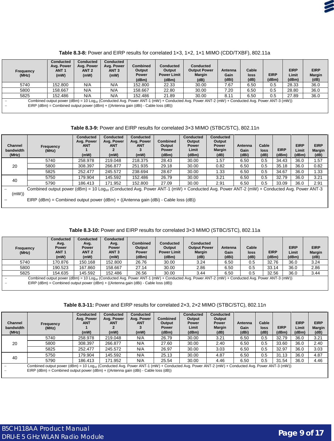
![Page 7 of 17 B5CH118AA Product Manual DRU-E 5 GHz WLAN Radio Module 5725-5850 MHz – Part 15.247 Subpart C For operation in the 5725-5850 MHz ISM band, the B5CH118AA may be set to operate on 20 MHz and 40 MHz channel bandwidths. POINT-TO-MULTIPOINT (MAXIMUM OUTPUT POWER SHOWN AS PTX): Table 8.3-1: Power and EIRP results for not correlated 3×3 MIMO, 802.11n Channel bandwidth (MHz) Frequency (MHz) Conducted Avg. Power ANT 1 (mW) Conducted Avg. Power ANT 2 (mW) Conducted Avg. Power ANT 3 (mW) Combined Output Power (dBm) Conducted Output Power Limit (dBm) Conducted Output Power Margin (dB) Antenna Gain (dBi) Cable loss (dB) EIRP (dBm) EIRP Limit (dBm) EIRP Margin (dB) 20 5740 258.978 219.048 218.375 28.43 30.00 1.57 6.50 0.5 34.43 36.0 1.57 5800 308.397 266.877 251.935 29.18 30.00 0.82 6.50 0.5 35.18 36.0 0.82 5825 252.477 245.572 238.694 28.67 30.00 1.33 6.50 0.5 34.67 36.0 1.33 40 5750 179.904 145.592 152.486 26.79 30.00 3.21 6.50 0.5 32.79 36.0 3.21 5790 186.413 171.952 152.800 27.09 30.00 2.91 6.50 0.5 33.09 36.0 2.91 − Combined output power (dBm) = 10 Log10 (Conducted Avg. Power ANT-1 (mW) + Conducted Avg. Power ANT-2 (mW) + Conducted Avg. Power ANT-3 (mW)) − EIRP (dBm) = Combined output power (dBm) + ((Antenna gain (dBi) - Cable loss (dB)) − Combined 3 antennae gain (dBi) = 6.5 [dBi] + 10×Log10(3) = 11.27 dBi − Limit (dBm) = 30 − ((11.27 − 0.5) − (6.5 − 0.5)) = 30 − (10.77 − 6.0) = 25.23 dBm Table 8.3-2: Power and EIRP results for not correlated 3×3 MIMO, 802.11a Frequency (MHz) Conducted Avg. Power ANT 1 (mW) Conducted Avg. Power ANT 2 (mW) Conducted Avg. Power ANT 3 (mW) Combined Output Power (dBm) Conducted Output Power Limit (dBm) Conducted Output Power Margin (dB) Antenna Gain (dBi) Cable loss (dB) EIRP (dBm) EIRP Limit (dBm) EIRP Margin (dB) 5740 170.876 150.168 152.800 26.76 30.00 3.24 6.50 0.5 32.76 36.0 3.24 5800 190.523 167.860 158.667 27.14 30.00 2.86 6.50 0.5 33.14 36.0 2.86 5825 154.635 145.592 152.486 26.56 30.00 3.44 6.50 0.5 32.56 36.0 3.44 − Combined output power (dBm) = 10 Log10 (Conducted Avg. Power ANT-1 (mW) + Conducted Avg. Power ANT-2 (mW) + Conducted Avg. Power ANT-3 (mW)) − EIRP (dBm) = Combined output power (dBm) + ((Antenna gain (dBi) - Cable loss (dB)) Table 8.3-3: Power and EIRP results for correlated 3×3 MIMO (CDD/TXBF), 802.11n Channel bandwidth (MHz) Frequency (MHz) Conducted Avg. Power ANT 1 (mW) Conducted Avg. Power ANT 2 (mW) Conducted Avg. Power ANT 3 (mW) Combined Output Power (dBm) Conducted Output Power Limit (dBm) Conducted Output Power Margin (dB) Antenna Gain (dBi) Cable loss (dB) EIRP (dBm) EIRP Limit (dBm) EIRP Margin (dB) 20 5740 114.412 98.730 109.247 25.08 25.23 0.15 11.27 0.5 35.85 36.0 0.15 5800 108.002 108.976 101.075 25.02 25.23 0.21 11.27 0.5 35.79 36.0 0.21 5825 115.169 108.231 106.576 25.18 25.23 0.05 11.27 0.5 35.95 36.0 0.05 40 5750 118.614 98.017 100.255 25.01 25.23 0.22 11.27 0.5 35.78 36.0 0.22 5790 105.095 101.559 77.897 24.54 25.23 0.69 11.27 0.5 35.31 36.0 0.69 − Combined output power (dBm) = 10 Log10 (Conducted Avg. Power ANT-1 (mW) + Conducted Avg. Power ANT-2 (mW) + Conducted Avg. Power ANT-3 (mW)) − EIRP (dBm) = Combined output power (dBm) + ((Antenna gain (dBi) - Cable loss (dB)) − Combined 3 antennae gain (dBi) = 6.5 [dBi] + 10×Log10(3) = 11.27 dBi − Limit (dBm) = 30 − ((11.27 − 0.5) − (6.5 − 0.5)) = 30 − (10.77 − 6.0) = 25.23 dBm](https://usermanual.wiki/Ericsson-Wi-Fi/50005001.Users-Manual/User-Guide-2338921-Page-7.png)
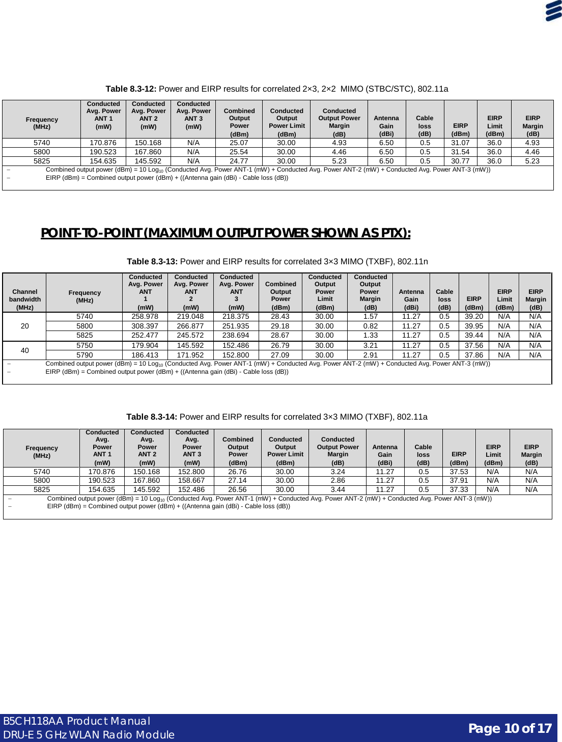
![Page 8 of 17 B5CH118AA Product Manual DRU-E 5 GHz WLAN Radio Module Table 8.3-4: Power and EIRP results for correlated 3×3 MIMO (CDD/TXBF), 802.11a Frequency (MHz) Conducted Avg. Power ANT 1 (mW) Conducted Avg. Power ANT 2 (mW) Conducted Avg. Power ANT 3 (mW) Combined Output Power (dBm) Conducted Output Power Limit (dBm) Conducted Output Power Margin (dB) Antenna Gain (dBi) Cable loss (dB) EIRP (dBm) EIRP Limit (dBm) EIRP Margin (dB) 5740 108.816 97.136 105.151 24.93 25.23 0.30 11.27 0.5 35.70 36.0 0.30 5800 123.704 112.594 90.544 25.14 25.23 0.09 11.27 0.5 35.91 36.0 0.09 5825 112.131 103.394 107.960 25.10 25.23 0.13 11.27 0.5 35.87 36.0 0.13 − Combined output power (dBm) = 10 Log10 (Conducted Avg. Power ANT-1 (mW) + Conducted Avg. Power ANT-2 (mW) + Conducted Avg. Power ANT-3 (mW)) − EIRP (dBm) = Combined output power (dBm) + ((Antenna gain (dBi) - Cable loss (dB)) − Combined 3 antennae gain (dBi) = 6.5 [dBi] + 10×Log10(3) = 11.27 dBi − Limit (dBm) = 30 − ((11.27 − 0.5) − (6.5 − 0.5)) = 30 − (10.77 − 6.0) = 25.23 dBm Table 8.3-5: Power and EIRP results for correlated 2×3, 2×2 MIMO (CDD/TXBF), 802.11n Channel bandwidth (MHz) Frequency (MHz) Conducted Avg. Power ANT 1 (mW) Conducted Avg. Power ANT 2 (mW) Conducted Avg. Power ANT 3 (mW) Combined Output Power (dBm) Conducted Output Power Limit (dBm) Conducted Output Power Margin (dB) Antenna Gain (dBi) Cable loss (dB) EIRP (dBm) EIRP Limit (dBm) EIRP Margin (dB) 20 5740 258.978 219.048 N/A 26.79 27.00 0.21 9.50 0.5 35.79 36.0 0.21 5800 248.781 223.106 N/A 26.74 27.00 0.26 9.50 0.5 35.74 36.0 0.26 5825 252.477 245.572 N/A 26.97 27.00 0.03 9.50 0.5 35.97 36.0 0.03 40 5750 179.904 145.592 N/A 25.13 27.00 1.87 9.50 0.5 34.13 36.0 1.87 5790 186.413 171.952 N/A 25.54 27.00 1.46 9.50 0.5 34.54 36.0 1.46 − Combined output power (dBm) = 10 Log10 (Conducted Avg. Power ANT-1 (mW) + Conducted Avg. Power ANT-2 (mW) + Conducted Avg. Power ANT-3 (mW)) − EIRP (dBm) = Combined output power (dBm) + ((Antenna gain (dBi) - Cable loss (dB)) − Combined 2 antennae gain (dBi) = 6.5 [dBi] + 10×Log10(2) = 9.5 dBi − Limit (dBm) = 30 − ((9.5 − 0.5) − (6.5 − 0.5)) = 30 − (9.0 − 6.0) = 27.00 dBm Table 8.3-6: Power and EIRP results for correlated 2×3, 2×2 MIMO (CDD/TXBF), 802.11a Frequency (MHz) Conducted Avg. Power ANT 1 (mW) Conducted Avg. Power ANT 2 (mW) Conducted Avg. Power ANT 3 (mW) Combined Output Power (dBm) Conducted Output Power Limit (dBm) Conducted Output Power Margin (dB) Antenna Gain (dBi) Cable loss (dB) EIRP (dBm) EIRP Limit (dBm) EIRP Margin (dB) 5740 170.876 150.168 N/A 25.07 27.00 1.93 9.50 0.5 34.07 36.0 1.93 5800 190.523 167.860 N/A 25.54 27.00 1.46 9.50 0.5 34.54 36.0 1.46 5825 154.635 145.592 N/A 24.77 27.00 2.23 9.50 0.5 33.77 36.0 2.23 − Combined output power (dBm) = 10 Log10 (Conducted Avg. Power ANT-1 (mW) + Conducted Avg. Power ANT-2 (mW) + Conducted Avg. Power ANT-3 (mW)) − EIRP (dBm) = Combined output power (dBm) + ((Antenna gain (dBi) - Cable loss (dB)) − Combined 2 antennae gain (dBi) = 6.5 [dBi] + 10×Log10(2) = 9.5 dBi − Limit (dBm) = 30 − ((9.5 − 0.5) − (6.5 − 0.5)) = 30 − (9.0 − 6.0) = 27.00 dBm Table 8.3-7: Power and EIRP results for correlated 1×3, 1×2, 1×1 MIMO (CDD/TXBF), 802.11n Channel bandwidth (MHz) Frequency (MHz) Conducted Avg. Power ANT 1 (mW) Conducted Avg. Power ANT 2 (mW) Conducted Avg. Power ANT 3 (mW) Combined Output Power (dBm) Conducted Output Power Limit (dBm) Conducted Output Power Margin (dB) Antenna Gain (dBi) Cable loss (dB) EIRP (dBm) EIRP Limit (dBm) EIRP Margin (dB) 20 5740 258.978 N/A N/A 24.13 30.00 5.87 6.50 0.5 30.13 36.0 5.87 5800 308.397 N/A N/A 24.89 30.00 5.11 6.50 0.5 30.89 36.0 5.11 5825 252.477 N/A N/A 24.02 30.00 5.98 6.50 0.5 30.02 36.0 5.98 40 5750 179.904 N/A N/A 22.55 30.00 7.45 6.50 0.5 28.55 36.0 7.45 5790 186.413 N/A N/A 22.70 30.00 7.30 6.50 0.5 28.70 36.0 7.30 − Combined output power (dBm) = 10 Log10 (Conducted Avg. Power ANT-1 (mW) + Conducted Avg. Power ANT-2 (mW) + Conducted Avg. Power ANT-3 (mW)) − EIRP (dBm) = Combined output power (dBm) + ((Antenna gain (dBi) - Cable loss (dB))](https://usermanual.wiki/Ericsson-Wi-Fi/50005001.Users-Manual/User-Guide-2338921-Page-8.png)