Ericsson Wi Fi 50005001 DRUE 5 GHz radio User Manual
Ericsson Wi-Fi DRUE 5 GHz radio Users Manual
Contents
- 1. product manual
- 2. Users Manual
Users Manual

Page 1 of 17
B5CH118AA Product Manual
DRU-E 5 GHz WLAN Radio Module
B5CH118AA
B5CH118AA Product Manual
DRU-E 5 GHz WLAN Radio Module
Document Date: July 7, 2014
Document Number: B5CH118AA
Document Version Number: 1
Document Status: Released
© Copyright 2013 by Ericsson AB.
All rights reserved.

Page 2 of 17
B5CH118AA Product Manual
DRU-E 5 GHz WLAN Radio Module
Contents
About this
Document
...................................................................2
Introduction
..................................................................................3
Conditions of Use .........................................................................4
Module Installation and Service.................................................5
Final Product
Requirements
........................................................6
Regulatory
Statements
..............................................................14
About this Document
This document is a product manual for the DRU-E 5 GHz WLAN
Radio Module, including its limitations on use in any product
marketed or offered for sale. It is intended as a supplement to
training and documentation by Ericsson Inc. or its authorized
agents.

Page 3 of 17
B5CH118AA Product Manual
DRU-E 5 GHz WLAN Radio Module
Introduction
The B5CH118AA (hereafter referred to as “the module”) is a 5 GHz radio module
compatible with the IEEE 802.11 standard for Wireless LAN operation. It is designed
to be interoperable with WLAN products which are based on Orthogonal
Frequency Division Multiplexing (OFDM) radio technology.
The module contains a complete IEEE 802.11a/n radio and Medium Access Control
(MAC) protocol engine which allows implementation of an IEEE 802.11a/n access
point (AP).
The module is not intended for stand-alone operation. It will only be marketed as a
complete product, in conjunction with a package, DC power supply and antennas
(hereafter referred to as “the product” or the “final product”).
The module can be used in the 5 GHz U-NII / ISM bands.
Since the module has an Ericsson proprietary digital interface, it cannot be
directly connected to any standard telecommunications or computer devices. It
can only be used with final products designed and authorized specifically for that
purpose.

Page 4 of 17
B5CH118AA Product Manual
DRU-E 5 GHz WLAN Radio Module
Conditions of Use
General Conditions of Use
This manual is intended to supplement training provided by Ericsson or
authorized parties. The module B5CH118AA is only intended for use in Ericsson
products and is not for sale to the general public as a stand-alone module.
Please read this entire document, including the Regulatory Statements section
before attempting to install or operate the module.
Warning: Any use of B5CH118AA in any manner which is not expressly specified
within this manual or specifically approved by Ericsson or its authorized agents will
void the user’s right to operate this module, and is expressly forbidden by Ericsson.
This includes any modification of the module, installation of the module in a
configuration or used with antennas which are not expressly listed in this document
or approved by Ericsson.

Page 5 of 17
B5CH118AA Product Manual
DRU-E 5 GHz WLAN Radio Module
Country of Use
B5CH118AA is certified with limited modular approval for use as an Intentional
Radiator in the United States as device: FCC ID: RAR50005001 and in Canada as
IC: 4674A-50005001. Please read all regulatory statements at the end of this
document before any attempt to install or operate this module.
The module is only certified for operation in the United States and Canada. Before
attempting to install and operate this module in any other country, contact
Ericsson for approval.
Module Labeling
One or more labels are applied to the module during manufacture, including a
label which identifies the FCC and Industry Canada identification numbers. Do not
attempt to remove any labels from the module.
Module Installation and Service
Installation into a Product
The module shall only be installed by a technician trained by Ericsson or its
authorized agents. It should only be installed into an approved product (see
above) following all manufacturing and service procedures for that product. The
module should only be installed into a final product in a manufacturing or service
depot site.
Caution: B5CH118AA is an electro-static discharge (ESD) sensitive device. All
appropriate ESD measures must be taken when handling the module. Failure to
employ appropriate ESD protection may damage the module.
Module Service
The module is not intended as a field-serviceable unit. It contains no field-
replaceable or field-serviceable parts, or any external adjustable mechanisms. The
module should only be serviced in a manufacturing or service depot site approved
by Ericsson or its authorized agents.

Page 6 of 17
B5CH118AA Product Manual
DRU-E 5 GHz WLAN Radio Module
Final Product Requirements
The requirements below apply to any final product in which the B5CH118AA
module is installed.
Antenna Usage and Module Transmit Power
The DRU-E 5GHz radio module supports MIMO 3x3 configuration with three transmit
chains and three receive chains. The B5CH118AA module shall only be used at the
following output power levels in conjunction with the following antenna types as
outlined in the tables that follow.
5725-5850 MHz – Part 15 Subpart E
For operation in the 5725-5850 MHz NII band, the B5CH118AA may be set to
operate on 20 MHz.
Table 8.3-2: Power and EIRP results for 3x3 MIMO 802.11n (SM-MIMO and STBC
operation)
Frequency
(MHz)
Conducted
Avg.
Power
ANT 1
(mW)
Conducted
Avg.
Power
ANT 2
(mW)
Conducted
Avg.
Power
ANT 3
(mW)
Combined
Output
Power
(dBm)
Conducted
Output
Power Limit
(dBm)
Conducted
Output Power
Margin
(dB)
Antenna
Gain
(dBi)
Cable
loss
(dB)
EIRP
(dBm)
EIRP
Limit
(dBm)
EIRP
Margin
(dB)
5740 154.195 139.172 143.151 26.40 30.00 3.60 6.50 0.5 32.40 36.0 3.60
5800
214.642
205.475
159.745
27.63
30.00
2.37
6.50
0.5
33.63
36.0
2.37
5825
213.854
182.772
181.802
27.62
30.00
2.38
6.50
0.5
33.62
36.0
2.38
− Combined output power (dBm) = 10 Log10 (Conducted Avg. Power ANT-1 (mW) + Conducted Avg. Power ANT-2 (mW) + Conducted Avg. Power ANT-3 (mW))
− EIRP (dBm) = Combined output power (dBm) + ((Antenna gain (dBi) - Cable loss (dB))

Page 7 of 17
B5CH118AA Product Manual
DRU-E 5 GHz WLAN Radio Module
5725-5850 MHz – Part 15.247 Subpart C
For operation in the 5725-5850 MHz ISM band, the B5CH118AA may be set to
operate on 20 MHz and 40 MHz channel bandwidths.
POINT-TO-MULTIPOINT (MAXIMUM OUTPUT POWER SHOWN AS PTX):
Table 8.3-1: Power and EIRP results for not correlated 3×3 MIMO, 802.11n
Channel
bandwidth
(MHz)
Frequency
(MHz)
Conducted
Avg. Power
ANT
1
(mW)
Conducted
Avg. Power
ANT
2
(mW)
Conducted
Avg. Power
ANT
3
(mW)
Combined
Output
Power
(dBm)
Conducted
Output
Power
Limit
(dBm)
Conducted
Output
Power
Margin
(dB)
Antenna
Gain
(dBi)
Cable
loss
(dB)
EIRP
(dBm)
EIRP
Limit
(dBm)
EIRP
Margin
(dB)
20
5740
258.978
219.048
218.375
28.43
30.00
1.57
6.50
0.5
34.43
36.0
1.57
5800
308.397
266.877
251.935
29.18
30.00
0.82
6.50
0.5
35.18
36.0
0.82
5825 252.477 245.572 238.694 28.67 30.00 1.33 6.50 0.5 34.67 36.0 1.33
40
5750
179.904
145.592
152.486
26.79
30.00
3.21
6.50
0.5
32.79
36.0
3.21
5790 186.413 171.952 152.800 27.09 30.00 2.91 6.50 0.5 33.09 36.0 2.91
− Combined output power (dBm) = 10 Log10 (Conducted Avg. Power ANT-1 (mW) + Conducted Avg. Power ANT-2 (mW) + Conducted Avg. Power ANT-3 (mW))
− EIRP (dBm) = Combined output power (dBm) + ((Antenna gain (dBi) - Cable loss (dB))
− Combined 3 antennae gain (dBi) = 6.5 [dBi] + 10×Log10(3) = 11.27 dBi
− Limit (dBm) = 30 − ((11.27 − 0.5) − (6.5 − 0.5)) = 30 − (10.77 − 6.0) = 25.23 dBm
Table 8.3-2: Power and EIRP results for not correlated 3×3 MIMO, 802.11a
Frequency
(MHz)
Conducted
Avg. Power
ANT 1
(mW)
Conducted
Avg. Power
ANT 2
(mW)
Conducted
Avg. Power
ANT 3
(mW)
Combined
Output
Power
(dBm)
Conducted
Output
Power Limit
(dBm)
Conducted
Output Power
Margin
(dB)
Antenna
Gain
(dBi)
Cable
loss
(dB)
EIRP
(dBm)
EIRP
Limit
(dBm)
EIRP
Margin
(dB)
5740
170.876
150.168
152.800
26.76
30.00
3.24
6.50
0.5
32.76
36.0
3.24
5800
190.523
167.860
158.667
27.14
30.00
2.86
6.50
0.5
33.14
36.0
2.86
5825
154.635
145.592
152.486
26.56
30.00
3.44
6.50
0.5
32.56
36.0
3.44
− Combined output power (dBm) = 10 Log10 (Conducted Avg. Power ANT-1 (mW) + Conducted Avg. Power ANT-2 (mW) + Conducted Avg. Power ANT-3 (mW))
− EIRP (dBm) = Combined output power (dBm) + ((Antenna gain (dBi) - Cable loss (dB))
Table 8.3-3: Power and EIRP results for correlated 3×3 MIMO (CDD/TXBF), 802.11n
Channel
bandwidth
(MHz)
Frequency
(MHz)
Conducted
Avg. Power
ANT
1
(mW)
Conducted
Avg. Power
ANT
2
(mW)
Conducted
Avg. Power
ANT
3
(mW)
Combined
Output
Power
(dBm)
Conducted
Output
Power
Limit
(dBm)
Conducted
Output
Power
Margin
(dB)
Antenna
Gain
(dBi)
Cable
loss
(dB)
EIRP
(dBm)
EIRP
Limit
(dBm)
EIRP
Margin
(dB)
20
5740
114.412
98.730
109.247
25.08
25.23
0.15
11.27
0.5
35.85
36.0
0.15
5800
108.002
108.976
101.075
25.02
25.23
0.21
11.27
0.5
35.79
36.0
0.21
5825 115.169 108.231 106.576 25.18 25.23 0.05 11.27 0.5 35.95 36.0 0.05
40
5750
118.614
98.017
100.255
25.01
25.23
0.22
11.27
0.5
35.78
36.0
0.22
5790
105.095
101.559
77.897
24.54
25.23
0.69
11.27
0.5
35.31
36.0
0.69
− Combined output power (dBm) = 10 Log10 (Conducted Avg. Power ANT-1 (mW) + Conducted Avg. Power ANT-2 (mW) + Conducted Avg. Power ANT-3 (mW))
− EIRP (dBm) = Combined output power (dBm) + ((Antenna gain (dBi) - Cable loss (dB))
− Combined 3 antennae gain (dBi) = 6.5 [dBi] + 10×Log10(3) = 11.27 dBi
− Limit (dBm) = 30 − ((11.27 − 0.5) − (6.5 − 0.5)) = 30 − (10.77 − 6.0) = 25.23 dBm
Page 8 of 17
B5CH118AA Product Manual
DRU-E 5 GHz WLAN Radio Module
Table 8.3-4: Power and EIRP results for correlated 3×3 MIMO (CDD/TXBF), 802.11a
Frequency
(MHz)
Conducted
Avg.
Power
ANT 1
(mW)
Conducted
Avg.
Power
ANT 2
(mW)
Conducted
Avg.
Power
ANT 3
(mW)
Combined
Output
Power
(dBm)
Conducted
Output
Power Limit
(dBm)
Conducted
Output Power
Margin
(dB)
Antenna
Gain
(dBi)
Cable
loss
(dB)
EIRP
(dBm)
EIRP
Limit
(dBm)
EIRP
Margin
(dB)
5740
108.816
97.136
105.151
24.93
25.23
0.30
11.27
0.5
35.70
36.0
0.30
5800
123.704
112.594
90.544
25.14
25.23
0.09
11.27
0.5
35.91
36.0
0.09
5825
112.131
103.394
107.960
25.10
25.23
0.13
11.27
0.5
35.87
36.0
0.13
− Combined output power (dBm) = 10 Log10 (Conducted Avg. Power ANT-1 (mW) + Conducted Avg. Power ANT-2 (mW) + Conducted Avg. Power ANT-3 (mW))
− EIRP (dBm) = Combined output power (dBm) + ((Antenna gain (dBi) - Cable loss (dB))
− Combined 3 antennae gain (dBi) = 6.5 [dBi] + 10×Log10(3) = 11.27 dBi
− Limit (dBm) = 30 − ((11.27 − 0.5) − (6.5 − 0.5)) = 30 − (10.77 − 6.0) = 25.23 dBm
Table 8.3-5: Power and EIRP results for correlated 2×3, 2×2 MIMO (CDD/TXBF), 802.11n
Channel
bandwidth
(MHz)
Frequency
(MHz)
Conducted
Avg. Power
ANT
1
(mW)
Conducted
Avg. Power
ANT
2
(mW)
Conducted
Avg. Power
ANT
3
(mW)
Combined
Output
Power
(dBm)
Conducted
Output
Power
Limit
(dBm)
Conducted
Output
Power
Margin
(dB)
Antenna
Gain
(dBi)
Cable
loss
(dB)
EIRP
(dBm)
EIRP
Limit
(dBm)
EIRP
Margin
(dB)
20
5740
258.978
219.048
N/A
26.79
27.00
0.21
9.50
0.5
35.79
36.0
0.21
5800 248.781 223.106 N/A 26.74 27.00 0.26 9.50 0.5 35.74 36.0 0.26
5825 252.477 245.572 N/A 26.97 27.00 0.03 9.50 0.5 35.97 36.0 0.03
40
5750
179.904
145.592
N/A
25.13
27.00
1.87
9.50
0.5
34.13
36.0
1.87
5790
186.413
171.952
N/A
25.54
27.00
1.46
9.50
0.5
34.54
36.0
1.46
− Combined output power (dBm) = 10 Log
10
(Conducted Avg. Power ANT-1 (mW) + Conducted Avg. Power ANT-2 (mW) + Conducted Avg. Power ANT-3 (mW))
− EIRP (dBm) = Combined output power (dBm) + ((Antenna gain (dBi) - Cable loss (dB))
− Combined 2 antennae gain (dBi) = 6.5 [dBi] + 10×Log10(2) = 9.5 dBi
− Limit (dBm) = 30 − ((9.5 − 0.5) − (6.5 − 0.5)) = 30 − (9.0 − 6.0) = 27.00 dBm
Table 8.3-6: Power and EIRP results for correlated 2×3, 2×2 MIMO (CDD/TXBF), 802.11a
Frequency
(MHz)
Conducted
Avg. Power
ANT 1
(mW)
Conducted
Avg. Power
ANT 2
(mW)
Conducted
Avg. Power
ANT 3
(mW)
Combined
Output
Power
(dBm)
Conducted
Output
Power Limit
(dBm)
Conducted
Output Power
Margin
(dB)
Antenna
Gain
(dBi)
Cable
loss
(dB)
EIRP
(dBm)
EIRP
Limit
(dBm)
EIRP
Margin
(dB)
5740
170.876
150.168
N/A
25.07
27.00
1.93
9.50
0.5
34.07
36.0
1.93
5800
190.523
167.860
N/A
25.54
27.00
1.46
9.50
0.5
34.54
36.0
1.46
5825
154.635
145.592
N/A
24.77
27.00
2.23
9.50
0.5
33.77
36.0
2.23
− Combined output power (dBm) = 10 Log10 (Conducted Avg. Power ANT-1 (mW) + Conducted Avg. Power ANT-2 (mW) + Conducted Avg. Power ANT-3 (mW))
− EIRP (dBm) = Combined output power (dBm) + ((Antenna gain (dBi) - Cable loss (dB))
− Combined 2 antennae gain (dBi) = 6.5 [dBi] + 10×Log10(2) = 9.5 dBi
− Limit (dBm) = 30 − ((9.5 − 0.5) − (6.5 − 0.5)) = 30 − (9.0 − 6.0) = 27.00 dBm
Table 8.3-7: Power and EIRP results for correlated 1×3, 1×2, 1×1 MIMO (CDD/TXBF), 802.11n
Channel
bandwidth
(MHz)
Frequency
(MHz)
Conducted
Avg. Power
ANT
1
(mW)
Conducted
Avg. Power
ANT
2
(mW)
Conducted
Avg. Power
ANT
3
(mW)
Combined
Output
Power
(dBm)
Conducted
Output
Power
Limit
(dBm)
Conducted
Output
Power
Margin
(dB)
Antenna
Gain
(dBi)
Cable
loss
(dB)
EIRP
(dBm)
EIRP
Limit
(dBm)
EIRP
Margin
(dB)
20
5740
258.978
N/A
N/A
24.13
30.00
5.87
6.50
0.5
30.13
36.0
5.87
5800
308.397
N/A
N/A
24.89
30.00
5.11
6.50
0.5
30.89
36.0
5.11
5825 252.477 N/A N/A 24.02 30.00 5.98 6.50 0.5 30.02 36.0 5.98
40
5750
179.904
N/A
N/A
22.55
30.00
7.45
6.50
0.5
28.55
36.0
7.45
5790
186.413
N/A
N/A
22.70
30.00
7.30
6.50
0.5
28.70
36.0
7.30
− Combined output power (dBm) = 10 Log
10
(Conducted Avg. Power ANT-1 (mW) + Conducted Avg. Power ANT-2 (mW) + Conducted Avg. Power ANT-3 (mW))
− EIRP (dBm) = Combined output power (dBm) + ((Antenna gain (dBi) - Cable loss (dB))

Page 9 of 17
B5CH118AA Product Manual
DRU-E 5 GHz WLAN Radio Module
Table 8.3-8: Power and EIRP results for correlated 1×3, 1×2, 1×1 MIMO (CDD/TXBF), 802.11a
Frequency
(MHz)
Conducted
Avg. Power
ANT 1
(mW)
Conducted
Avg. Power
ANT 2
(mW)
Conducted
Avg. Power
ANT 3
(mW)
Combined
Output
Power
(dBm)
Conducted
Output
Power Limit
(dBm)
Conducted
Output Power
Margin
(dB)
Antenna
Gain
(dBi)
Cable
loss
(dB)
EIRP
(dBm)
EIRP
Limit
(dBm)
EIRP
Margin
(dB)
5740
152.800
N/A
N/A
152.800
22.33
30.00
7.67
6.50
0.5
28.33
36.0
5800 158.667 N/A N/A 158.667 22.80 30.00 7.20 6.50 0.5 28.80 36.0
5825
152.486
N/A
N/A
152.486
21.89
30.00
8.11
6.50
0.5
27.89
36.0
− Combined output power (dBm) = 10 Log
10
(Conducted Avg. Power ANT-1 (mW) + Conducted Avg. Power ANT-2 (mW) + Conducted Avg. Power ANT-3 (mW))
− EIRP (dBm) = Combined output power (dBm) + ((Antenna gain (dBi) - Cable loss (dB))
Table 8.3-9: Power and EIRP results for correlated 3×3 MIMO (STBC/STC), 802.11n
Channel
bandwidth
(MHz)
Frequency
(MHz)
Conducted
Avg. Power
ANT
1
(mW)
Conducted
Avg. Power
ANT
2
(mW)
Conducted
Avg. Power
ANT
3
(mW)
Combined
Output
Power
(dBm)
Conducted
Output
Power
Limit
(dBm)
Conducted
Output
Power
Margin
(dB)
Antenna
Gain
(dBi)
Cable
loss
(dB)
EIRP
(dBm)
EIRP
Limit
(dBm)
EIRP
Margin
(dB)
20
5740
258.978
219.048
218.375
28.43
30.00
1.57
6.50
0.5
34.43
36.0
1.57
5800 308.397 266.877 251.935 29.18 30.00 0.82 6.50 0.5 35.18 36.0 0.82
5825 252.477 245.572 238.694 28.67 30.00 1.33 6.50 0.5 34.67 36.0 1.33
40
5750
179.904
145.592
152.486
26.79
30.00
3.21
6.50
0.5
32.79
36.0
3.21
5790 186.413 171.952 152.800 27.09 30.00 2.91 6.50 0.5 33.09 36.0 2.91
− Combined output power (dBm) = 10 Log10 (Conducted Avg. Power ANT-1 (mW) + Conducted Avg. Power ANT-2 (mW) + Conducted Avg. Power ANT-3
(mW))
− EIRP (dBm) = Combined output power (dBm) + ((Antenna gain (dBi) - Cable loss (dB))
Table 8.3-10: Power and EIRP results for correlated 3×3 MIMO (STBC/STC), 802.11a
Frequency
(MHz)
Conducted
Avg.
Power
ANT 1
(mW)
Conducted
Avg.
Power
ANT 2
(mW)
Conducted
Avg.
Power
ANT 3
(mW)
Combined
Output
Power
(dBm)
Conducted
Output
Power Limit
(dBm)
Conducted
Output Power
Margin
(dB)
Antenna
Gain
(dBi)
Cable
loss
(dB)
EIRP
(dBm)
EIRP
Limit
(dBm)
EIRP
Margin
(dB)
5740
170.876
150.168
152.800
26.76
30.00
3.24
6.50
0.5
32.76
36.0
3.24
5800
190.523
167.860
158.667
27.14
30.00
2.86
6.50
0.5
33.14
36.0
2.86
5825
154.635
145.592
152.486
26.56
30.00
3.44
6.50
0.5
32.56
36.0
3.44
−
Combined output power (dBm) = 10 Log10 (Conducted Avg. Power ANT-1 (mW) + Conducted Avg. Power ANT-2 (mW) + Conducted Avg. Power ANT-3 (mW))
− EIRP (dBm) = Combined output power (dBm) + ((Antenna gain (dBi) - Cable loss (dB))
Table 8.3-11: Power and EIRP results for correlated 2×3, 2×2 MIMO (STBC/STC), 802.11n
Channel
bandwidth
(MHz)
Frequency
(MHz)
Conducted
Avg. Power
ANT
1
(mW)
Conducted
Avg. Power
ANT
2
(mW)
Conducted
Avg. Power
ANT
3
(mW)
Combined
Output
Power
(dBm)
Conducted
Output
Power
Limit
(dBm)
Conducted
Output
Power
Margin
(dB)
Antenna
Gain
(dBi)
Cable
loss
(dB)
EIRP
(dBm)
EIRP
Limit
(dBm)
EIRP
Margin
(dB)
20
5740
258.978
219.048
N/A
26.79
30.00
3.21
6.50
0.5
32.79
36.0
3.21
5800
308.397
266.877
N/A
27.60
30.00
2.40
6.50
0.5
33.60
36.0
2.40
5825
252.477
245.572
N/A
26.97
30.00
3.03
6.50
0.5
32.97
36.0
3.03
40
5750
179.904
145.592
N/A
25.13
30.00
4.87
6.50
0.5
31.13
36.0
4.87
5790
186.413
171.952
N/A
25.54
30.00
4.46
6.50
0.5
31.54
36.0
4.46
− Combined output power (dBm) = 10 Log
10
(Conducted Avg. Power ANT-1 (mW) + Conducted Avg. Power ANT-2 (mW) + Conducted Avg. Power ANT-3 (mW))
− EIRP (dBm) = Combined output power (dBm) + ((Antenna gain (dBi) - Cable loss (dB))

Page 10 of 17
B5CH118AA Product Manual
DRU-E 5 GHz WLAN Radio Module
Table 8.3-12: Power and EIRP results for correlated 2×3, 2×2 MIMO (STBC/STC), 802.11a
Frequency
(MHz)
Conducted
Avg. Power
ANT 1
(mW)
Conducted
Avg. Power
ANT 2
(mW)
Conducted
Avg. Power
ANT 3
(mW)
Combined
Output
Power
(dBm)
Conducted
Output
Power Limit
(dBm)
Conducted
Output Power
Margin
(dB)
Antenna
Gain
(dBi)
Cable
loss
(dB)
EIRP
(dBm)
EIRP
Limit
(dBm)
EIRP
Margin
(dB)
5740
170.876
150.168
N/A
25.07
30.00
4.93
6.50
0.5
31.07
36.0
4.93
5800 190.523 167.860 N/A 25.54 30.00 4.46 6.50 0.5 31.54 36.0 4.46
5825
154.635
145.592
N/A
24.77
30.00
5.23
6.50
0.5
30.77
36.0
5.23
− Combined output power (dBm) = 10 Log
10
(Conducted Avg. Power ANT-1 (mW) + Conducted Avg. Power ANT-2 (mW) + Conducted Avg. Power ANT-3 (mW))
− EIRP (dBm) = Combined output power (dBm) + ((Antenna gain (dBi) - Cable loss (dB))
POINT-TO-POINT (MAXIMUM OUTPUT POWER SHOWN AS PTX):
Table 8.3-13: Power and EIRP results for correlated 3×3 MIMO (TXBF), 802.11n
Channel
bandwidth
(MHz)
Frequency
(MHz)
Conducted
Avg. Power
ANT
1
(mW)
Conducted
Avg. Power
ANT
2
(mW)
Conducted
Avg. Power
ANT
3
(mW)
Combined
Output
Power
(dBm)
Conducted
Output
Power
Limit
(dBm)
Conducted
Output
Power
Margin
(dB)
Antenna
Gain
(dBi)
Cable
loss
(dB)
EIRP
(dBm)
EIRP
Limit
(dBm)
EIRP
Margin
(dB)
20
5740
258.978
219.048
218.375
28.43
30.00
1.57
11.27
0.5
39.20
N/A
N/A
5800 308.397 266.877 251.935 29.18 30.00 0.82 11.27 0.5 39.95 N/A N/A
5825 252.477 245.572 238.694 28.67 30.00 1.33 11.27 0.5 39.44 N/A N/A
40
5750
179.904
145.592
152.486
26.79
30.00
3.21
11.27
0.5
37.56
N/A
N/A
5790 186.413 171.952 152.800 27.09 30.00 2.91 11.27 0.5 37.86 N/A N/A
− Combined output power (dBm) = 10 Log10 (Conducted Avg. Power ANT-1 (mW) + Conducted Avg. Power ANT-2 (mW) + Conducted Avg. Power ANT-3 (mW))
− EIRP (dBm) = Combined output power (dBm) + ((Antenna gain (dBi) - Cable loss (dB))
Table 8.3-14: Power and EIRP results for correlated 3×3 MIMO (TXBF), 802.11a
Frequency
(MHz)
Conducted
Avg.
Power
ANT 1
(mW)
Conducted
Avg.
Power
ANT 2
(mW)
Conducted
Avg.
Power
ANT 3
(mW)
Combined
Output
Power
(dBm)
Conducted
Output
Power Limit
(dBm)
Conducted
Output Power
Margin
(dB)
Antenna
Gain
(dBi)
Cable
loss
(dB)
EIRP
(dBm)
EIRP
Limit
(dBm)
EIRP
Margin
(dB)
5740
170.876
150.168
152.800
26.76
30.00
3.24
11.27
0.5
37.53
N/A
N/A
5800
190.523
167.860
158.667
27.14
30.00
2.86
11.27
0.5
37.91
N/A
N/A
5825
154.635
145.592
152.486
26.56
30.00
3.44
11.27
0.5
37.33
N/A
N/A
− Combined output power (dBm) = 10 Log
10
(Conducted Avg. Power ANT-1 (mW) + Conducted Avg. Power ANT-2 (mW) + Conducted Avg. Power ANT-3 (mW))
− EIRP (dBm) = Combined output power (dBm) + ((Antenna gain (dBi) - Cable loss (dB))

Page 11 of 17
B5CH118AA Product Manual
DRU-E 5 GHz WLAN Radio Module
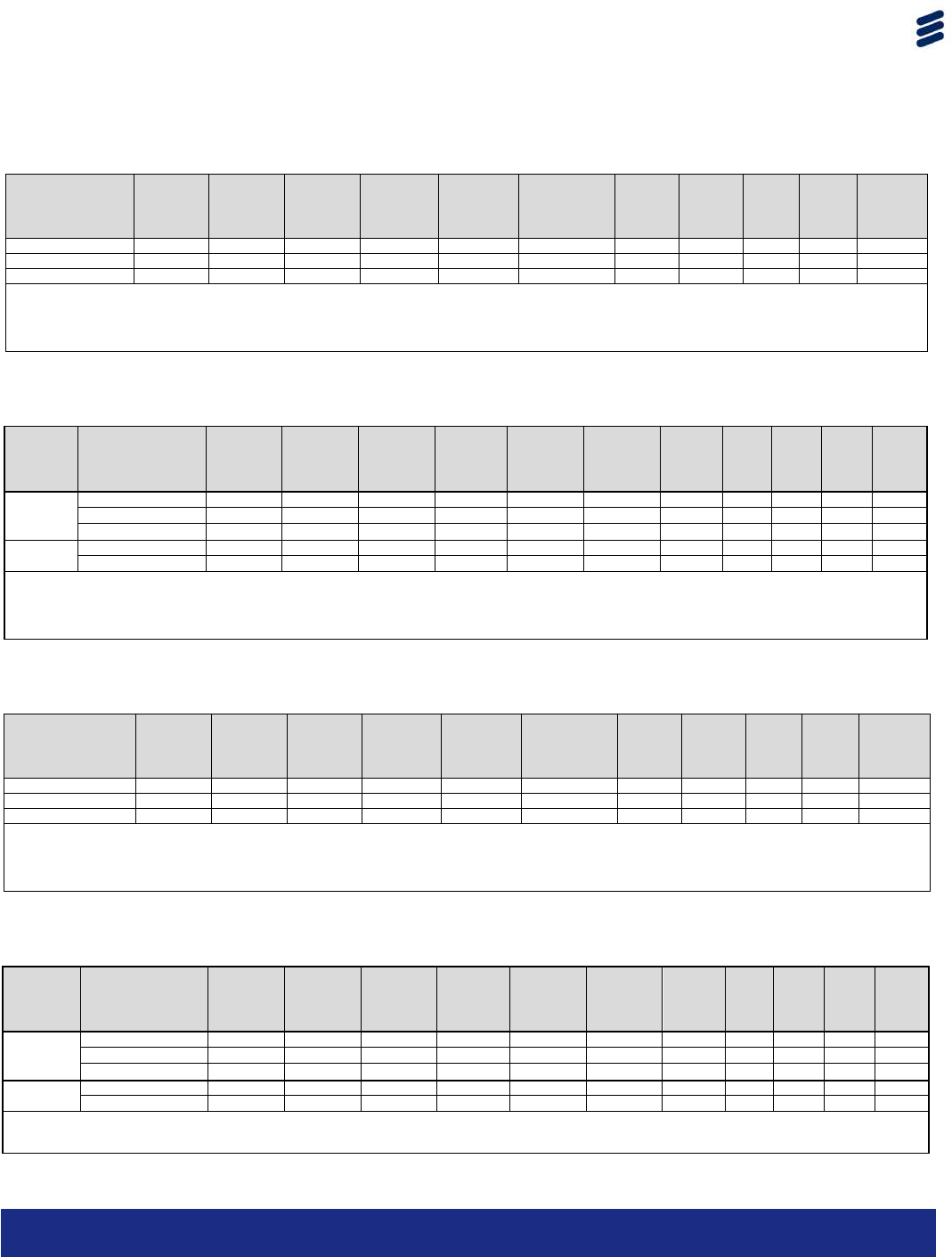
5150-5250 MHz – Part 15 Subpart E
For operation in the 5150-5250 MHz U-NII band, the B5CH118AA may be set
to operate on 20 MHz and 40 MHz channel bandwidths.
Table 8.4-1: EIRP calculation for correlated MIMO 3x3 with 6.5 dBi antennas
Modulation Frequency
(MHz)
Conducted
Avg. Power
ANT 1
(dBm)
Conducted
Avg.
Power
ANT 2
(dBm)
Conducted
Avg.
Power
ANT 3
(dBm)
Combined
Output
Power
(dBm)
Conducted
Output
Power Limit
(dBm)
Conducted
Output Power
Margin
(dB)
Total
antenna
Gain
(dBi)
EIRP
(dBm)
802.11a
5180
16.50
16.77
16.30
21.30
25.23
3.93
11.27
32.57
5200
16.30
16.62
16.30
21.18
25.23
4.05
11.27
32.45
5220
16.78
16.14
16.61
21.29
25.23
3.94
11.27
32.56
802.11n HT20
5180
16.15
16.17
16.17
20.93
25.23
4.29
11.27
32.21
5200
16.32
16.12
15.79
20.85
25.23
4.38
11.27
32.12
5220
16.62
15.64
16.12
20.92
25.23
4.31
11.27
32.19
802.11n HT40
5190
11.68
12.64
13.08
17.28
25.23
7.95
11.27
28.55
5210
14.01
14.31
14.37
19.00
25.23
6.22
11.27
30.28
Note: In order to comply with elevation mask of 6.5 dBi antenna the maximum EIRP shall below 32.8 dBm.
Table 8.4-2: EIRP calculation for correlated MIMO 3x3 with 4 dBi antennas
Modulation Frequency
(MHz)
Conducted
Avg. Power
ANT 1
(dBm)
Conducted
Avg.
Power
ANT 2
(dBm)
Conducted
Avg.
Power
ANT 3
(dBm)
Combined
Output
Power
(dBm)
Conducted
Output
Power Limit
(dBm)
Conducted
Output Power
Margin
(dB)
Total
antenna
Gain
(dBi)
EIRP
(dBm)
802.11a
5180
7.12
7.54
7.70
12.23
27.73
15.50
8.77
21.00
5200
7.34
7.04
6.73
11.82
27.73
15.91
8.77
20.59
5220 7.71 6.81 7.09 11.99 27.73 15.74 8.77 20.76
802.11n HT20
5180
7.11
6.68
7.12
11.75
27.73
15.98
8.77
20.52
5200
7.29
7.00
6.73
11.78
27.73
15.94
8.77
20.56
5220
7.66
6.83
7.05
11.97
27.73
15.76
8.77
20.74
802.11n HT40
5190
7.32
7.42
7.37
12.14
27.73
15.59
8.77
20.91
5210
7.38
7.66
7.13
12.17
27.73
15.56
8.77
20.94
Note: 4 dBi antenna gain configuration has ≤21 dBm EIRP results, therefore elevation mask is not applicable.
Table 8.4-3: EIRP calculation for uncorrelated MIMO 3x3 with 6.5 dBi antennas
Modulation Frequency
(MHz)
Conducted
Avg. Power
ANT 1
(dBm)
Conducted
Avg.
Power
ANT 2
(dBm)
Conducted
Avg.
Power
ANT 3
(dBm)
Combined
Output
Power
(dBm)
Conducted
Output
Power Limit
(dBm)
Conducted
Output Power
Margin
(dB)
Antenna
Gain
(dBi)
EIRP
(dBm)
802.11a
5180
18.23
18.58
18.69
23.28
30.00
6.72
6.5
29.78
5200
21.81
21.27
21.27
26.23
30.00
3.77
6.5
32.73
5220
21.67
21.27
21.58
26.28
30.00
3.72
6.5
32.78
802.11n HT20
5180
18.19
17.94
18.16
22.87
30.00
7.13
6.5
29.37
5200
21.77
20.54
20.61
25.78
30.00
4.22
6.5
32.28
5220
21.12
21.24
21.55
26.08
30.00
3.92
6.5
32.58
802.11n HT40 5190 13.96 15.16 15.61 19.74 30.00 10.26 6.5 26.24
5210
16.83
17.88
17.43
22.17
30.00
7.83
6.5
28.67
Note: In order to comply with elevation mask of 6.5 dBi antenna the maximum EIRP shall below 32.8 dBm.
Table 8.4-4: EIRP calculation for uncorrelated MIMO 3x3 with 4 dBi antennas
Modulation Frequency
(MHz)
Conducted
Avg. Power
ANT 1
(dBm)
Conducted
Avg.
Power
ANT 2
(dBm)
Conducted
Avg.
Power
ANT 3
(dBm)
Combined
Output
Power
(dBm)
Conducted
Output
Power Limit
(dBm)
Conducted
Output Power
Margin
(dB)
Antenna
Gain
(dBi)
EIRP
(dBm)
802.11a
5180
11.73
12.08
12.19
16.78
30.00
13.22
4.00
20.78
5200
12.81
11.77
11.77
16.92
30.00
13.08
4.00
20.92
5220
12.67
11.27
11.58
16.65
30.00
13.35
4.00
20.65
802.11n HT20
5180
11.69
11.44
11.66
16.37
30.00
13.63
4.00
20.37
5200
13.27
11.54
11.11
16.85
30.00
13.15
4.00
20.85
5220
12.62
11.74
11.55
16.77
30.00
13.23
4.00
20.77
802.11n HT40
5190
11.82
11.92
11.87
16.64
30.00
13.36
4.00
20.64
5210
11.88
11.66
11.63
16.50
30.00
13.50
4.00
20.50
Note: 4 dBi antenna gain configuration has ≤21 dBm EIRP results, therefore elevation mask is not applicable.
Page 12 of 17
B5CH118AA Product Manual
DRU-E 5 GHz WLAN Radio Module
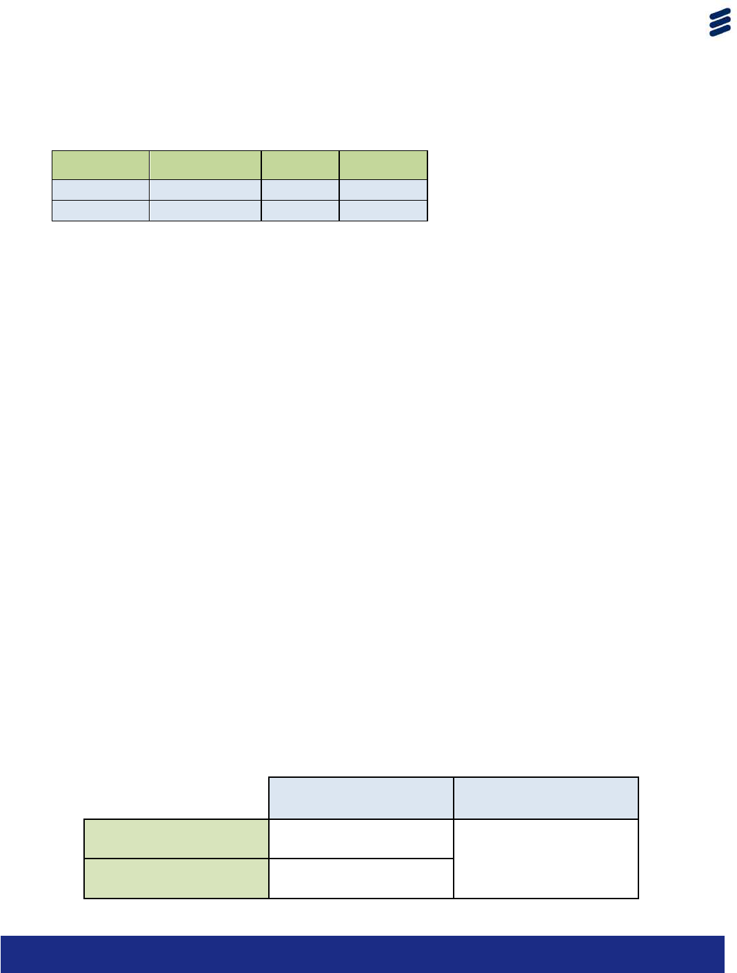
Certified Antennas:
The following antennas are certified for use:
Manufacturer
Part #
Gain (dBi)
Type
Ericsson
B1BG123AA‐A
6.5
OMNI
Ericsson
B1BG154AA‐A
4.0
OMNI
Note: 4.0 dBi antenna is for 5150‐5250 MHz only.
In order to comply with the FCC and Industry Canada rules in the USA and
Canada, respectively, it is required to respect the maximum transmit power limits as
follows for each of the antenna types as indicated in the above tables.
Warning: Use of this module in conjunction with any antenna not expressly listed
above will void authority to install or operate this equipment.
Warning: Setting of module transmit power above the limits specified in the above
table for a particular combination of antenna type, frequency of operation, and
type of usage, will exceed FCC or Industry Canada limits and void authority to
install or operate this equipment.
Product Installation
Products which contain B5CH118AA shall only be installed by professional installers
trained by Ericsson or its authorized agents. This product is to be installed on fixed
permanent structures. In addition to normal installation procedures and
good installation practice, professional installers are responsible to ensure that:
1. Only an approved antenna (see above) is connected to the module, and,
2. The antenna is mounted in such a manner and in such a location that access to
the antenna by the general population is minimized. Access to the antenna by
the general population should be limited to more than the minimum safety
distance. This distances are outlined according to product type and whether
high gain antennas are used:
Max E.I.R.P
Minimum
Safety
Distance
DRU-E 2.4 GHz radio
37.85 dB
14.2 inches
DRU-E 5 GHz radio
39.95 dB
Page 13 of 17
B5CH118AA Product Manual
DRU-E 5 GHz WLAN Radio Module
Adherence to these rules by the professional installer is mandatory. See full
installation procedures for the particular product for details.
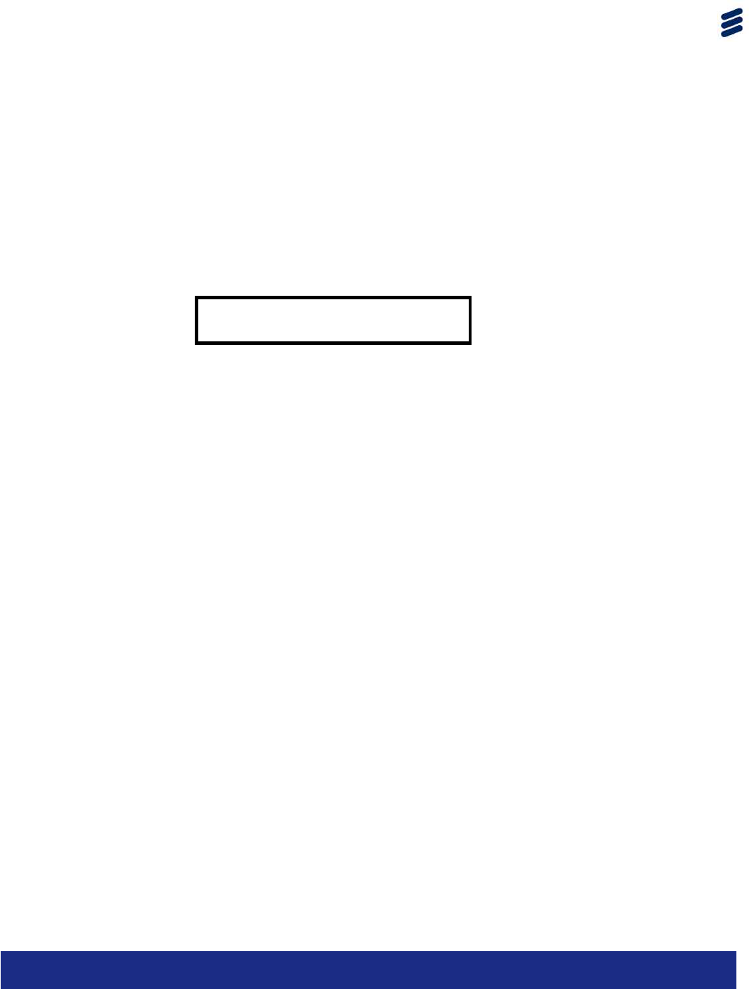
Product Labeling
The following permanent label, or one containing equivalent information, must be
affixed in a conspicuous location on the exterior of every product containing this
module:
This device contains the following:
FCC ID: RAR50005001

Page 14 of 17
B5CH118AA Product Manual
DRU-E 5 GHz WLAN Radio Module
Regulatory Statements
The following regulatory notes apply to the product which contains module
B5CH118AA. The following sections or equivalent information shall appear in the
user-manual of the final product.
Regulatory Information and Disclaimers
Installation and use of this device must be in strict accordance with the instructions
included in the user documentation provided with the product. Any changes or
modifications to this product not expressly approved by the party responsible for
compliance could void the user’s authority to operate this equipment.
The manufacturer is not responsible for any interference to radio or television
equipment caused by unauthorized modification of this device, or attachment of
any antennas or equipment other than those specified by the manufacturer. The
manufacturer or its authorized resellers or distributors will assume no liability for any
damage or violation of government regulations arising from failing to comply with
these guidelines.
Manufacturer’s FCC Conformity Statement
This device complies with Part 15 of the FCC Rules.
Operation is subject to the following two conditions (1) this device may not cause
harmful interference, and (2) this device must accept any interference received,
including interference that may cause undesired operation.
FCC Interference Statement
This equipment has been tested and found to comply with the limits for a Class B
digital device, pursuant to Part 15 of the FCC Rules. These limits are designed to
provide reasonable protection against harmful interference in a residential
installation. This equipment generates, uses, and can radiate radio frequency
energy and, if not installed and used in accordance with the instructions, may
cause harmful interference to radio communications. However, there is no
guarantee that interference will not occur in a particular installation. If this
equipment does cause harmful interference to radio or television reception, which
can be determined by turning the equipment off and on, the user is encouraged
to try to correct the interference by one or more of the following measures:
• Reorient or relocate the receiving antenna.

Page 15 of 17
B5CH118AA Product Manual
DRU-E 5 GHz WLAN Radio Module
• Increase the separation between the equipment and receiver.
• Connect the equipment into an outlet on a circuit different from that to which
the receiver is connected.
• Consult the dealer or an experienced radio/TV technician for help.
Manufacturer’s Industry Canada Conformity Statement
This device has been designed to operate with an antenna having a maximum
gain of 6.5 dBi. Antenna having a higher gain is strictly prohibited per regulations of
Industry Canada. The required antenna impedance is 50 ohms.
This device has been designed to ensure that radio frequency emissions are
maintained within the band of operation under all normal operating conditions
listed in this manual.
Operation is subject to the following two conditions: (1) this device may not cause
interference, and (2) this device must accept any interference, including
interference that may cause undesired operation of the device.
To reduce potential radio interference to other users, the antenna type and its gain
should be so chosen that the equivalent isotropic radiated power (EIRP) is not more
than that required for successful communication.
This Class B Digital apparatus meets all the requirements of the Canadian
Interference-Causing Equipment Regulations.
Cet appareil a été conçu pour fonctionner avec une antenne avec un gain
maximum de 4.5dBi. L’utilisation d’ antennes de gain supérieur est strictement
défendue selon la réglementation d’Industrie Canada.
Cet appareil a été conçu a garantir que les émissions de fréquences radio soit
maintenues dans la bande d’opération sous toutes les conditions énoncé dans ce
manuel.
Son utilisation est soumise aux deux conditions suivantes: (1) Cet appareil ne doit
pas être la cause d’interférence, et (2) cet appareil doit pouvoir être capable de
recevoir toutes sortes d’interférences, incluant l’interférence qui pourrait affecter le
bon fonctionnement de cet appareil.

Page 16 of 17
B5CH118AA Product Manual
DRU-E 5 GHz WLAN Radio Module
Pour réduire le potentiel d’interférence radio sur d’autres utilisateurs, le type
d’antenne et son gain doivent être choisies tel que la Puissance Isotrope Rayonnée
Equivalente (PIRE) ne dépasse pas le niveau nécessaire pour une communication
efficace.
Cet appareil Digitale de Classe B rencontre toutes les normes du Canadian
Interference-Causing Equipment Regulations.
RF Exposure Statement
This Wireless LAN radio device has been evaluated under FCC Bulletin OET 65C and
Health Canada Safety Code 6, and found to be compliant to the requirements set
forth in CFR 47 Sections 2.1091, 2.1093, and 15.247 (b) (4) addressing RF exposure
from radio frequency devices.
This device complies with IC and FCC RF exposure limits for an uncontrolled
environment. The radiated output power of this Wireless LAN device is below the IC
and FCC radio frequency exposure limits. However, this device should be installed
and used in such a manner that the potential for human contact during normal
operation is minimized. In order to comply with RF exposure limits, this equipment
should be installed and operated at a minimum distance between the radiator
and a human body. This minimum distance is:
Max E.I.R.P
Minimum
Safety
Distance
DRU-E 2.4 GHz radio
37.85 dB
14.2 inches
DRU-E 5 GHz radio
39.95 dB
Cet appareil radio LAN sans-fils a été évalué par le FCC Bulletin OET 65C and le
code de sécurité 6 de santé Canada, et est conforme a toutes les normes de la
section FCR 47 Sections 2.1091, 2.1093, and 15.247 (b) (4) qui s’adressent a
l’exposition FR d’appareil utilisant des fréquences radios.
Cet appareil se conforme selon IC et FCC RF pour l’exposition maximum dans un
environnement non-contrôlé. Le puissance de rayonnement de cet appareil LAN

Page 17 of 17
B5CH118AA Product Manual
DRU-E 5 GHz WLAN Radio Module
est dessous les limites d’exposition de fréquences radio selon IC et FCC. Toutefois,
cet appareil doit être installé et utilise de manière a limiter au minimum le contact
humain durant son utilisation normal. Afin de respecter l’exposition limite des FR, cet
appareil doit être installé et utilisé a une distance minimale entre le radiateur et le
corps humain. La distance minimale est:
Max E.I.R.P Distance Minimale de
Séruité
DRU-E 2.4 GHz radio
37.85 dB
14.2 inches
DRU-E 5 GHz radio
39.95 dB
© Ericsson AB 2013. All rights reserved. No part of this
document may be reproduced in any form without the written
permission of the copyright owner.
The contents of this document are subject to revision without
notice due to continued progress in methodology, design and
manufacturing. Ericsson shall have no liability for any error or
damage of any kind resulting from the use of this document.