Ericsson 0130101-BV Fixed Cellular Terminal User Manual INTRODUCTION
Ericsson AB Fixed Cellular Terminal INTRODUCTION
Ericsson >
Exhibit 8 User Manual
1/70
User guide
F251m terminal
Fixed Cellular Terminal for Small office Home office (SoHo) applications
2/70
1 F251m........................................................................................6
2 SUPPLIED PARTS ...................................................................7
3 EXTERNAL CONNECTORS AND LIGHT INDICATORS...7
4 SIM CARD................................................................................8
5 CONNECTIONS.......................................................................8
5.1 Installing the FCT as a telephone line .......................................8
5.2 Installing an FCT connected to a PBX ......................................9
5.3 Preparing your FCT.................................................................11
5.3.1 Assembly .................................................................................11
5.3.2 Connect a telephone to the FCT ..............................................12
5.3.3 Switch on the FCT...................................................................12
5.3.4 Enter PIN .................................................................................12
5.3.5 Network search ........................................................................13
5.4 Installing the FCT on the wall .................................................14
5.4.1 FCT Location...........................................................................14
5.4.2 Wall mounting .........................................................................15
5.5 Connecting fixed line devices..................................................17
5.5.1 Checking connections..............................................................18
5.5.2 Checking the calls quality:.......................................................18
6 USING TELEPHONES...........................................................19
7 USING CLI DISPLAYS..........................................................19
8 USING FAX MACHINES ......................................................21
8.1 Sending a fax: ..........................................................................21
8.2 Receiving a fax ........................................................................21
9 USING PCS.............................................................................21
9.1 GPRS data access type.............................................................22
9.2 GSM data access type..............................................................23
10 USING PBX ............................................................................25
11 ADVANCED FEATURES......................................................26
11.1 Changing volume.....................................................................26
11.2 Diverting calls (call forward)...................................................26
11.3 Restricting calls (call barring) .................................................27
11.4 More than one call (call wait, call hold, call transfer, multiparty
call) ..........................................................................................28
11.4.1 Call waiting service .................................................................29
3/70
11.4.2 Making a second call ...............................................................29
11.4.3 Receiving a second call ...........................................................29
11.4.4 Conference calls.......................................................................30
11.4.5 Connecting active and held calls .............................................30
11.5 Phonebook (abbreviated dialing).............................................30
11.6 Voice mail................................................................................31
11.7 Sending tone signals ................................................................31
11.8 Controlling call time (minute minder).....................................32
11.9 Emergency number (Hot line) .................................................32
11.10 Two voice lines (Alternate Line Service)................................33
11.11 SIM card security.....................................................................33
11.11.1 To manage your SIM card .......................................................33
11.11.2 To unblock your SIM card.......................................................34
11.11.3 To change your PIN.................................................................34
11.11.4 To unblock your SIM card while changing your PIN .............34
12 TROUBLESHOOTING AND FCT INDICATORS ...............35
12.1 Light indicators........................................................................35
12.2 Audible tones...........................................................................38
13 FCT TECHNICAL DATA ......................................................39
14 FCT ACCESSORIES ..............................................................42
14.1 ISDN Adapter FI12..................................................................42
14.2 Display Adapter DA20 ............................................................43
14.3 Antennas ..................................................................................43
14.4 Power supply ...........................................................................43
15 ANNEX: PC data configurations.............................................45
15.1 Windows 98 GPRS set-up .......................................................45
15.2 Windows NT GPRS set-up......................................................50
16 SAFE AND EFFICIENT USE ................................................57
16.1 Product care .............................................................................57
16.2 Antenna care............................................................................57
16.3 Radio frequency energy...........................................................58
16.4 Electronic devices....................................................................58
16.5 Potentially explosive atmospheres...........................................59
16.6 Power supply ...........................................................................59
16.7 Children ...................................................................................60
16.8 Disposing of the product..........................................................60
16.9 Battery information..................................................................60
16.10 Disposing of the battery...........................................................61
16.11 Moving or storing the FCT......................................................61
16.12 Accessing the battery compartment.........................................62
17 LIMITED WARRANTY.........................................................63
4/70
17.1 Limited Warranty Conditions..................................................63
17.2 Ericsson Warranty ...................................................................63
17.3 What Ericsson will do..............................................................63
17.4 Conditions................................................................................64
18 REGULATORY INFORMATION .........................................66
19 DEFINITIONS ........................................................................68
5/70
Ericsson F251m
First edition, November 2001
This manual has been published by Ericsson Radio Systems, AB, without any warranty.
Improvements and changes to this manual needed by typographical errors, inaccuracies
of current information, or improvements to programs and/or equipment, may be made by
Ericsson Radio Systems, AB at any time and without notice. Such changes will, however,
be incorporated into new editions of the manual.
All rights reserved
© Ericsson España, S.A. Bilbao Technology Centre, 2001
Publication number: EN/LZT 123 6904 R2A
Important information: Some of the services described in this guide might not be
supported by all networks. Please, contact your network operator for information
on different network services operational in your GSM network.

6/70
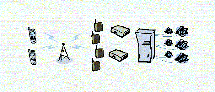
1 F251M
The F251m is a flexible and cost-effective solution for
connecting your SoHo telephone system to the digital wireless
GSM network.
When there is no fixed infrastructure or if you need additional
telephone lines:
install the terminal
run cabling from the F251m to any place within your Small
office Home office (SoHo) and
you will be ready to connect and use standard telephones,
fax machines, computers (Internet) and PBXs
The terminal features the latest technology, which makes it
perfect for everyday communication:
Triple band GSM (E-GSM 900, GSM 1800, GSM 1900)
Telephone line providing high quality speech (EFR), G3
fax and V.90 data transmission
GPRS (General Packet Radio Service), which is designed
to keep you always on line and facilitate rapid transmission
of data (ideal for e-mail and Internet browsing)
HSCSD (High Speed Circuit Switched Data) which further
enhances data transmission
Embedded modem available over the RS232 port
Battery back-up
7/70
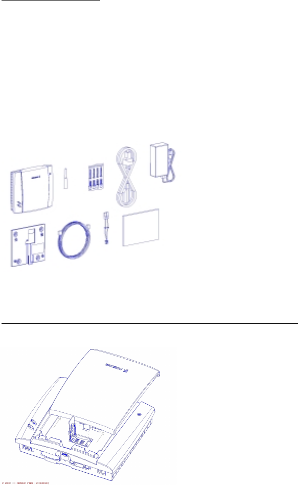
2 SUPPLIED PARTS
After unpacking check that the following parts are included:
- GSM FCT - Battery cable - AC power supply - Cable
- Antenna - Wall bracket - 5m phone cable - Screws
- User guide
- DA20 (optional) – Alkaline (AA) holder (optional)
3 EXTERNAL CONNECTORS AND LIGHT INDICATORS
- GSM radio indicator (greed led)
- Power indicator (red led)
- Telephone interface
- Antenna connector
- Power connector

8/70
- RS232 port
- Maintenance connector
- SIM card holder
4 SIM CARD
Your network operator provides you with a SIM (Subscriber
Identity Module) card. The SIM card contains information
about your telephone number and the services included in your
subscription, among other things.
Warning!: switch off the FCT before you insert or remove
your SIM card.
5 CONNECTIONS
Warning!: please, before you start any connections refer to
section “Safe and Efficient Use” on page 57 in this guide and
contact your network operator if you have any question.
Warning!: to get a good FCT protection against electrical
discharges and the best audio quality, a good grounding of
the Power Supply is strongly recommended.
5.1 INSTALLING THE FCT AS A TELEPHONE LINE
The FCT is designed to provide a telephone line (RJ11
connector) to which up to 3 Fixed Line Devices can be
connected in parallel. The FCT provides a single telephone
line, which means that only one communication can take place
simultaneously, in the same way as the ordinary fixed line (you
cannot, for example, receive or originate a telephone call while
sending or receiving a fax).
Note: you may be able to connect up to 5 telephone devices
depending on their characteristics. See “Ring Back Test” on
page 17
9/70
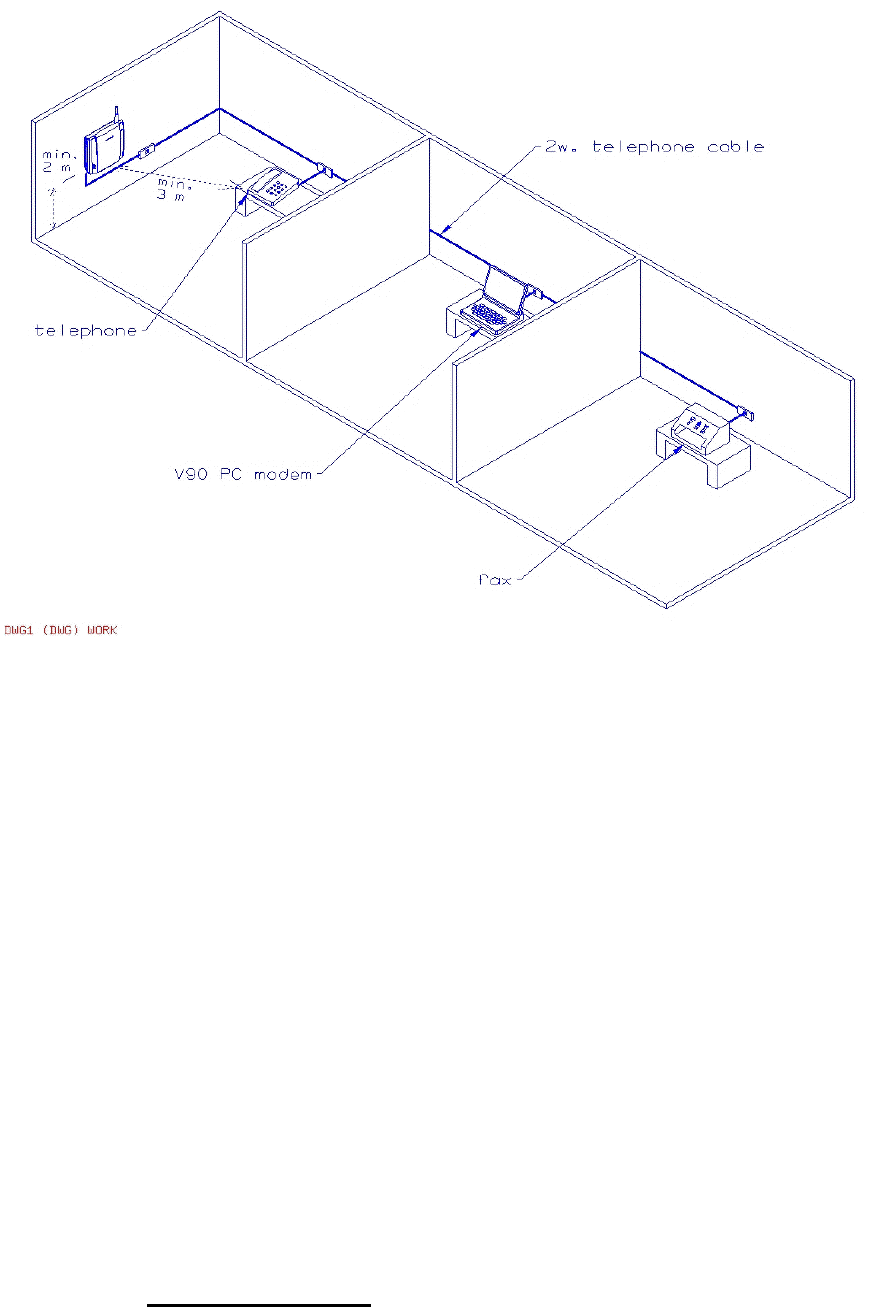
Warning!: In order to avoid GSM interferences (noises),
place the FCT at least 3 meters (horizontal) away from
electronic devices, including the telephone equipment
connected to the FCT, or other household electronic devices
such as televisions or radio receivers. The difference in
height should be at least 2 meters (vertical). This is not
necessary if you use telephone devices that fulfil the
Immunity Characteristics settled by the IEC CISPR-24
standard. In this case, a minimum security distance of 20 cm
is recommended.
The FCT is also equipped with an RS232 port that enables you
to use it as a GSM modem for PC Fax, Data and SMS services.
For this specific configuration, please refer to the FCT Data
Kit (see “FCT accessories” on page 41).
5.2 INSTALLING AN FCT CONNECTED TO A PBX
The FCT is designed to provide a telephone line (RJ11
connector) that behaves in the same way as an Analog Trunk.
Generic requirements
10/70
The PBX should meet the following generic requirements for
FCT connectivity:
• The PBX must offer the possibility of analog trunks.
Otherwise, the ISDN FI12 adapter accessory will be
necessary. (see “FCT accessories” on page 41).
• One position of the trunk must be assigned to each FCT
terminal.
• The trunk card must support either Busy Tone Detection
(BTD) or Polarity Reversal Detection on answer and
release.
• The PBX can be programmed to utilize Least Cost Router
(LCR), if available, to automatically choose the FCT trunk
when suitable.
• If the PBX does not offer LCR, choose the FCT trunk
manually with a special dialed prefix.
The F251m terminal is compatible with most analog PBXs on
the market and with most of the available 2B+D ISDN digital
output trunks, via its accessory ISDN FI12 adapter (see “FCT
accessories” on page 41).
FCT connectivity to the ISDN 2B+D trunk of the PBX
Follow the FCT installation instructions next (“Preparing your
FCT” and “Installing the FCT on the wall”) and then refer to
“Using PBX” on page 24.
11/70
Note: it is recommended that there is a minimum distance of 3
meters between the FCT and the PBX. The maximum cable
distance between the PBX and the FCT should not exceed 600
meters, and the connection cable must be at least 0,4 mm2.
Warning!: if you install more than one FCT to a PBX, their
antennas have to be separated with a distance of 20 cm in
height or 2 meters in horizontal.
5.3 PREPARING YOUR FCT
You need to follow the following procedure before you install
the FCT on the wall and make all definitive connections.
Warning!: switch off the FCT before you insert or remove
your SIM card or connect any device to the FCT.
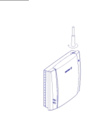
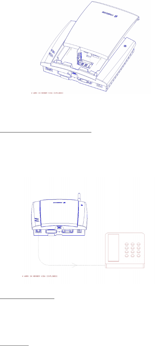
5.3.1 Assembly
1. Connect the antenna
2. Remove the front-cover. Open the SIM card holder and
place the SIM in the right position.
12/70
3. Close the SIM card holder and place the front cover back in
previous position.
5.3.2 Connect a telephone to the FCT
Connect a fixed telephone to the FCT telephone line.
Note: You will use this telephone for dialing the PIN number.
5.3.3 Switch on the FCT
Connect the Power Supply. The FCT switches on
automatically and the Green and Red light indicators start
flashing.
5.3.4 Enter PIN

13/70
Most SIM cards are protected with a PIN (Personal Identity
Number), which you get from your network operator and
which you need in order to access the network.
If the SIM card is not protected by the PIN code then you do
not need to enter the PIN and the FCT starts automatically the
Network Search.
If the SIM card is protected by the PIN code, then the Green
and Red light indicators flash simultaneously.
Note: if you have the DA20 display adapter accessory (See
“FCT accessories” on page 41), an “Enter PIN” message will
show on your display.
Follow the following procedure to enter the PIN:
Pick up the telephone and dial the PIN code. Press the #
key on your telephone or wait until you hear a beep tone.
If you make a mistake while entering your PIN, hang up
immediately the telephone down and try again.
If the PIN is correct, you will hear a beep over the telephone
(affirmative indication tone). If it is incorrect, a loud and low
tone will sound (error indication tone).
If your PIN is entered incorrectly three times, the SIM card
will be blocked. If this happens, you can unblock it by using
your PUK (Personal Unblocking Key), which you also get
from your network operator. See “SIM Card Security” on page
32
Note: once you have entered the PIN code for the first time
you will not have to enter it again unless you change your SIM
card. The FCT performs this operation automatically in case
of power failure.
5.3.5 Network search
After you have switched on your FCT and entered your PIN,
the FCT automatically searches for a network.
Note: if the Red Light is off, there is a problem with the power
supply. See “Troubleshooting and FCT indicators” on page 34

14/70
When a network is found, the Green Light Indicator switches
on or flashes depending on the GSM signal strength. (See
Light Indicators on page 6).
Note: if the Green Light is off you do not have access to the
GSM network at your present location.
Now you have prepared the FCT for wall installation. Please,
follow the instructions below for complete wall installation.
5.4 INSTALLING THE FCT ON THE WALL
5.4.1 FCT Location
The GSM signal strength present at the FCT location affects
the performance of the unit. The stronger the GSM signal is
the better for the FCT performance.
Tip: test several potential locations by moving the FCT while
looking at the Green Light indicator. Select the location where
the Green Light is steady, or the location with the highest
amount of flashes.
Note: moving the FCT as little as 20 cm can affect the GSM
reception quality.
Installation Location Testing
Number of Green Light flashes Location status
0 Unacceptable
1 - - - Acceptable
2 - - - - - - Good
3 - - - - - - - - - Very good
Steady ---------------------- Excellent
Please consider the following recommendations:
Select always an Indoor location, preferably close to a
window and the roof. Generally, you will experience better
GSM signal strength in these places.
15/70
Do not install the FCT in a bathroom, wet or damp
basement or in an outdoor location.
Do not install the FCT on walls or rooms that contain large
amounts of metal, steel or wiring.
Do not expose the FCT to extreme temperatures (near
radiators, cooling vents, etc).
If you experience poor reception quality, an outdoor antenna
may result in improvement. See “FCT accessories” on page 41
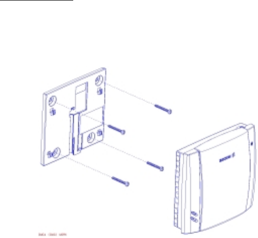
5.4.2 Wall mounting
Please proceed as indicated in the following picture.
1) Fix the wall mounting bracket on the wall
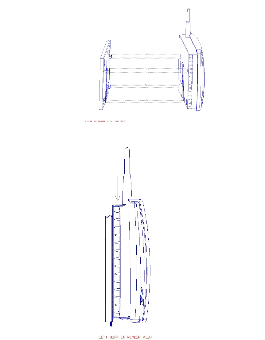
2) Insert the FCT in the wall mounting bracket
16/70
3) Press the FCT down
Warning!: once you have fixed the FCT to the wall and
switch it on, check the final status of the Red and Green
lights. If the Red and/or Green Lights are off, there is a
problem with the power supply or the GSM signal. See
“Troubleshooting and FCT indicators” on page 34
Now the FCT is ready for connecting devices and make calls.
17/70
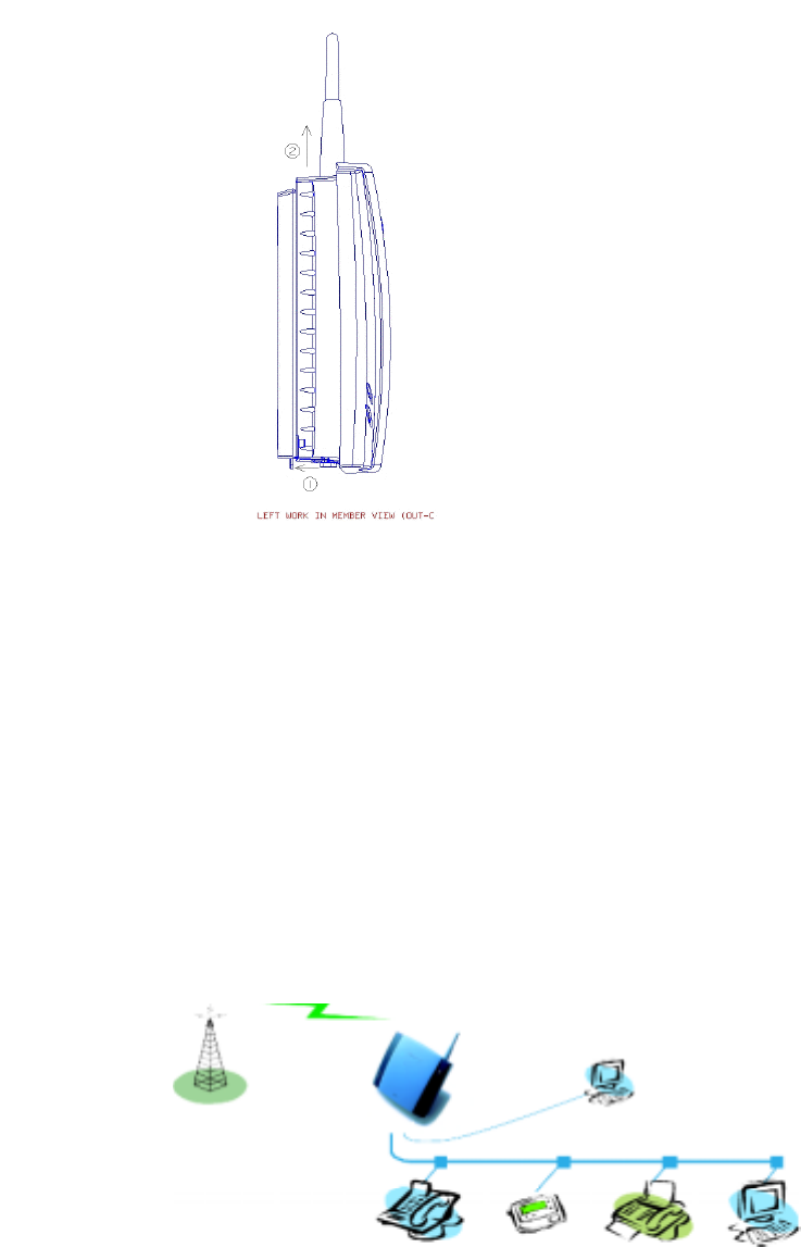
Note: if you want to remove the FCT from the wall bracket
then you have to press the flap (step 1) as indicated in the
following picture. And then push the FCT upwards (step 2).
5.5 CONNECTING FIXED LINE DEVICES
Connect the fixed line devices to the FCT (Telephone Line
connector) with telephone wire in the same way as with an
analog telephone line.
Fixed line devices are connected in parallel to the telephone
cable. You can connect the devices directly to the FCT
Telephone line connector (RJ11) or make an internal telephone
wiring, use RJ11 splitters or similar connectors.
GSM network
RS232

18/70
Telephone
Display
Fax
PC modem
Note: remember that you do not have to worry about the two
wire Telephone cable polarity when making connections; if the
two wires are reversed the FCT and the fixed line devices are
not affected at all.
Tip: if your house or company is already wired with telephone
cable, you only need to connect the cable to the FCT RJ11
connector and your telephone line will be up and running in all
rooms.
Note: it is strongly recommended that the telephone wire is
installed indoors in order to avoid lightning damage.
Note: the telephone wire should not exceed 600 meters. Larger
distances can be achieved by using high quality telephone
wire.
5.5.1 Checking connections
Once the fixed line devices (1 up to 3) have been connected,
make the “Ring Back Test” as follows in order to check the
connections:
Lift one telephone and dial **#10#. You will hear a beep
tone (the FCT Red and Green light indicators will start
flashing -three flashes synchronized).
Hung the telephone up and check if all the connected
telephones are ringing.
Lift any of the telephones connected and then pick it up
again. The ringing will stop (the red and green lights will
go to normal operation mode).
Tip: If any of the telephones has not been ringing, check your
telephone cable layout and connections to make sure that all
devices are properly connected.
5.5.2 Checking the calls quality:

19/70
Use any of the telephones connected to the FCT and make a
call. Check the speech quality and ask the receiver to call you
back to confirm that you can also receive calls.
If you have problems, see “Troubleshooting and FCT
indicators” on page 34
6 USING TELEPHONES
Fixed telephones connected to the FCT telephone line work in
the same way as if they were connected to a Fixed Network.
Note: you can also benefit from some FCT functionality that
you do not usually have on your fixed network. See “Advanced
features” on page 25
You can find more detailed information about the tones that
the FCT sends on “Audible Tones” page 37
7 USING CLI DISPLAYS
Devices for displaying incoming numbers (telephones with
display, external displays, etc.) can be directly connected to the
FCT line interface in the same way as an ordinary telephone. If
your subscription includes the Calling Line identification
(CLI) service and the caller´s network sends the number, the
FCT sends the caller´s number towards your CLI Display.
In general, your FCT will be programmed (according to your
country specifications) to send the CLI information with the
right standard so that your CLI device works properly.
Refer to your CLI Telephone or Display User Guide for
understanding your CLI indications.
Tip: if you run the “Ring Back Test” on page 17 (lift the
telephone, dial **#10# and hung up), you can check if the
following number “1234567890” appears on your CLI display.
If not, the FCT is not using the right standard.
If you experience that your CLI device is not showing the
calling numbers, you may need to change the FCT settings.
If you know the CLI standard used by your CLI device (check
the user guide from this device), you can dial directly the
specific sequence for this standard (see table below) from a
DTMF (Pulses) telephone connected to the FCT.

20/70
Otherwise, you can alternatively dial each of the following
sequences and check each time if the numbers appear on your
CLI display by conducting the “Ring Back Test” after a
specific sequence is dialed. You should find that one of the
three sequences allows you to visualize the number
“1234567890” on your display when the “Ring Back Test” is
conducted.
CLI standard Dialing sequence
ETSI DTMF **000*1#
ETSI V.23 **000*2#
Bellcore **000*3#
In order to disable the CLI Display functionality (not to see
CLI information anymore), dial **000*0# from a DTMF
(Pulses) telephone connected to the FCT.
Tip: if you do not want your telephone number to appear at the
caller’s location, you can dial the #31# before the phone
number you are going to call (B-number) (#31#B-Number)
To find out about the DA20 Display accessory, please check
“FCT accessories” on page 41.

21/70
8 USING FAX MACHINES
The FCT terminal allows the connection of Group 3 analog
faxes to the FCT telephone interface, in the same way as a
telephone.
Warning!: the fax communication service has to be
registered with your network operator, as the network will
not otherwise accept faxes to be sent/received.
8.1 SENDING A FAX:
The FCT terminal is programmed to automatically detect
outgoing calls made by an analog fax, meaning that the user
simply has to use the fax in the same way as a conventional
telephone line.
Warning!: if your fax is an old model and is not able to send
the fax identification CNG tone, you should include *01*
previous to the called number (B-number) in order to
indicate the FCT that the call to be made is a fax call
(Example: *01*B-number). This is not usually necessary, as
most faxes automatically send the CNG tone so that the fax
call is made automatically by the FCT.
8.2 RECEIVING A FAX
Incoming faxes are received in the same way as using the fixed
line.
Note: if you have a SIM card that does not support separate
voice and fax numbers, the FCT does not recognize the type of
incoming call. This means that the calling party will have to
warn you each time a fax is about to be sent. In this case, dial
*9901# to prepare your FCT to receive a fax call.
9 USING PCs
Analog modems connected to the FCT telephone line work in
the same way as if they were connected to the Fixed Network.
In this way, you can use your PC standard modem to make
22/70
data calls (Internet browsing, e-mail, etc.) through the FCT
line.
To be able to send and receive data calls, you need:
- a PC equipped with an analog modem and the appropriate
computer program (Web Browser, E-mail, etc). This is a
standard configuration for most PCs in the market.
- a SIM card that supports data transmission over the GSM
network.
Note: if you do not have a modem in your PC, the FCT can be
configured to act as a modem itself. This requires the
installation of the FCT modem drivers on your PC. For this
specific configuration, please refer to the FCT Data Kit (see
“FCT accessories” on page 41).
The FCT should be pre-configured with the settings from your
network operator. For detailed information on FCT data
configured settings, please consult your distributor or network
operator.
You can choose between two data access types (connection
methods):
GPRS (General Packet Radio Service) data: GPRS allows
fast and efficient access where you can be always online
(although you are only charged for the amount of
information that you exchange). You need a SIM card that
supports GPRS. Please contact your network operator for
charging subscription details.
GSM data: normally, you pay for all the time you are
connected. You need a SIM card that supports GSM data.
For fast and efficient access, try the GPRS access type.
9.1 GPRS DATA ACCESS TYPE
GPRS data access type allows you to make outgoing calls
only, usually to connect to the Internet.
Your GSM network operator provides you with an Internet
connection as part of the GPRS service.
23/70
Warning!: the GPRS data communication service has to be
registered with your network operator, as the network will
not otherwise accept GPRS calls.
If your SIM card supports GPRS, your network operator must
supply you with a user name and password in order to access
the GPRS network, and optionally, to improve the Internet
connection, a DNS address and a Proxy address.
You need to configure the Dial-up Networking program in
your PC in order to establish a GPRS connection.
Note: this procedure is similar to the way you configure an
Internet connection from a specific ISP (Internet Service
Provider).
If your network operator has provided you with an installation
guide, please follow the instructions included in the guide.
Otherwise, the present manual indicates the installation
process. As the Dial-up Networking is different for Windows
98 and Windows NT, two separate descriptions are provided.
See “ANNEX: PC Data Configurations” on page 44
If you encounter problems during installation, please contact
your distributor or network operator.
9.2 GSM DATA ACCESS TYPE
GSM data access type allows you to make both incoming and
outgoing data calls in the same way as with a fixed line.
Therefore, you can connect to the Internet using the same ISP
(Internet Service Provider) that you would use with a fixed
line.
The SIM card must support GSM data.
The network operator does not need to supply you with any
specific information, and it is your ISP the one that provides
you with the user name, password and installation information
in order to establish an Internet connection.
Please contact your ISP for installation instructions.
Note: your PC should be configured in exactly the same way
as if using the fixed line.

24/70
Tip: if you already have an Internet connection configured for
the fixed line, you do not need to make any changes, just
connect your PC to the FCT line instead of the fixed line.
Warning!: if your modem is an old model and is not able to
send the CNG tone, you should include *02* previous to the
called number(B-number) in order to indicate the FCT that
the call to be made is a data call (Example: *02*B-number).
This is not usually necessary, as most modems automatically
send the CNG tone so that the data call is made automatically
by the FCT.
Incoming data calls are received in the same way as using the
fixed line.
Note: if you have a SIM card that does not support separate
voice and data numbers, the FCT does not recognize the type
of incoming call. This means that the calling party will have to
warn you each time a data call is about to be made. In this
case, dial *9902# to prepare your FCT to receive a data call.

25/70
10 USING PBX
For a PBX connection, first, you should:
• Check that the PBX fulfills the requirements for FCT
connectivity (see “Installing an FCT connected to a PBX”
on page 8)
• Follow all FCT installation steps specified in “Preparing
your FCT” and “Installing the FCT on the wall” on pages
10 and 13
Warning!: the PBX may require specific programming; both
this and the FCT installation should be done by specialized
service personnel.
If you are using an analog PBX - Disconnect the telephone you
have used for testing purposes and connect the cable from the
chosen analog trunk of the PBX to the FCT telephone line.
If you are using a 2B+D ISDN digital PBX - Disconnect the
telephone you have used for testing purposes and follow the
instructions in the FI12 installation guide. (See “FCT
accessories” on page 41)
If you are using a Least Cost Routing (LCR) programmed
PBX, check your PBX programming guide to see how to
program your PBX to make certain calls through the FCT
trunk. Once LCR is programmed, make a call to a mobile
telephone number. See if the call is established through the
FCT and also check the speech quality. Ask the person who
answers to call you back to confirm that the installed FCT can
receive calls properly.
If the PBX does not offer the LCR option, choose the FCT
trunk manually with a specific prefix. Check the installation in
the same way as before.
If you encounter problems, please contact your Distributor or
network operator.

26/70
11 ADVANCED FEATURES
If a DTMF telephone is connected to the FCT, the following
features can be accessed
11.1 CHANGING VOLUME
During a call, you can increase or decrease the received
volume level.
• Increase volume: dial R####
• Decrease volume: dial R****
11.2 DIVERTING CALLS (CALL FORWARD)
You can divert incoming calls to another phone number when
you are unable to answer.
The following table shows the divert alternatives as well as the
way to proceed to manage this function
Warning!: these dialing sequences may vary depending on
your network operator. If these do not work, please consult
your network operator or check the user guide provided with
your subscription.

27/70
To manage
diversion of calls … With
Function … Dial … You will hear…
Activate **21*Phone_number# 1 beep
Deactivate ##21# 3 beeps
Always
Check status *#21# 1 beep if activated
3 beeps if deactivated
Activate **67*Phone_number# 1 beep
Deactivate ##67# 3 beeps
When busy
Check status *#67# 1 beep if activated
3 beeps if deactivated
Activate **61*Phone_number# 1 beep
Deactivate ##61# 3 beeps
When no answer
Check status *#61# 1 beep if activated
3 beeps if deactivated
Activate **62*Phone_number# 1 beep
Deactivate ##62# 3 beeps
When out of reach
Check status *#62# 1 beep if activated
3 beeps if deactivated
All Deactivate ##002# 3 beeps
Note: if instead of hearing beeps you hear a loud and low tone,
this means that there has been an error in the activation or
deactivation
11.3 RESTRICTING CALLS (CALL BARRING)
You can restrict certain types of calls that can be made or
received. You need a password to turn a call restriction on or
off. Initially, this password will be 0000.
We recommend you to change it by dialing:
**03**OLD_PASSWORD*NEW_PASSWORD*NEW_PASSWORD#
The following table shows the restriction alternatives as well
as the way to proceed to manage this function

28/70
Warning!: these dialing sequences may vary depending on
your network operator. If these do not work, please consult
your network operator or check the user guide provided with
your subscription.
To manage
restriction of calls
…
With
Function … Dial … You will hear…
Activate *33*Password# 1 beep
Deactivate #33*Password# 3 beeps
All outgoing calls
Check status *#33# 1 beep if activated
3 beeps if deactivated
Activate *331*Password# 1 beep
Deactivate #331*Password# 3 beeps
All outgoing
international calls
Check status *#331# 1 beep if activated
3 beeps if deactivated
Activate *332*Password# 1 beep
Deactivate #332*Password# 3 beeps
All outgoing
international calls
except your home
country Check status *#332# 1 beep if activated
3 beeps if deactivated
Activate *35*Password# 1 beep
Deactivate #35*Password# 3 beeps
All incoming calls
Check status *#35# 1 beep if activated
3 beeps if deactivated
Activate *351*Password# 1 beep
Deactivate #351*Password# 3 beeps
All incoming calls
when your are
abroad Check status *#351# 1 beep if activated
3 beeps if deactivated
All Deactivate #330*Password# 3 beeps
Note: if instead of hearing beeps you hear a loud and low tone,
this means that there has been an error in the activation or
deactivation
11.4 MORE THAN ONE CALL (CALL WAIT, CALL HOLD, CALL
TRANSFER, MULTIPARTY CALL)

29/70
You can handle more than one call simultaneously. For
example, you can put an ongoing call on hold, while you make
or answer a second call, and then switch between the two calls.
You can also set up a Conference call to have a joint
conversation with up to four people.
11.4.1 Call waiting service
If you wish to be able to receive a second call while another
call is in progress, you must turn on the Call waiting service.
Note: if you are engaged in a fax or a data call, any other
incoming calls are rejected.
Warning!: these dialing sequences may vary depending on
your network operator. If these do not work, please consult
your network operator or check the user guide provided with
your subscription.
To manage Call
waiting Function … Dial … You will hear…
Activate *43# 1 beep
Deactivate #43# 3 beeps
Check status *#43# 1 beep if activated
3 beeps if deactivated
Note: if instead of hearing beeps you hear a loud and low tone,
this means that there has been an error in the activation or
deactivation
11.4.2 Making a second call
You can only put one call on hold while you make a second
call.
• To hold the active call: press the R key on your telephone
and proceed to make the second call
11.4.3 Receiving a second call
If the call waiting service is on, you hear a tone in the
telephone when you receive a second call.

30/70
• To continue the ongoing call and reject the waiting call:
press R 0
• To put the ongoing call on hold and answer the waiting
call: press R 1
• To end the ongoing call and answer the waiting call: press
R 2
Note: if divert when busy is on, the waiting call is diverted to
the number you have specified
11.4.4 Conference calls
In a conference call, you can have a joint conversation with up
to four other people.
To create a conference call, you must have one active call and
one call on hold.
• To join the two call into a conference call: press R 3
You can put the conference group on hold (press R) in order
to:
• make a new call
• add the new call to the conference group: press R 3
To release a specific call from the conference group: press R 1
X (where X is the number of order of the call)
11.4.5 Connecting active and held calls
You can connect the active and held calls, but abandon the
conversation. To do this, press R 4
11.5 PHONEBOOK (ABBREVIATED DIALING)
You can store telephone numbers in either the SIM card
memory of the FCT memory. Up to 99 telephone numbers can
be stored in each of them.
The following table shows how to manage the phonebook with
the 99 memory positions (Pos)
31/70
Warning!: Pos has to have two digits always. For example,
memory position number 1 has Pos=01
To manage the
phonebook in … With
Function … Dial … You will hear…
Store **51*Pos*Phone_number# 1 beep
Delete #51*Pos# 3 beeps
Check position *#51*Pos*Phone_number# 1 beep if memorized
3 beeps if not
memorized
SIM card memory
Dial Pos# Dialing …
Store **51*Pos*Phone_number*1# 1 beep
Delete #51*Pos*1# 3 beeps
Check position *#51*Pos*Phone_number*1# 1 beep if memorized
3 beeps if not
memorized
FCT memory
Dial Pos* Dialing …
Note: if instead of hearing beeps you hear a loud and low tone,
this means that there has been an error in the activation or
deactivation
11.6 VOICE MAIL
The answering service of your network allows callers to leave
a voice message when you cannot answer your calls.
If you have voice mail, you will hear 3 beeps before the dial
tone, as soon as you pick up the receiver to make a call.
Note: if you have the DA20 display adapter accessory (See
“FCT accessories” on page 41), a icon will show when
you have voice mail.
Call your voice mail number in order to receive the voice mail
message.
11.7 SENDING TONE SIGNALS

32/70
During a call, you can press keys 0-9, * and # to perform
banking by phone or other interactive services, or control an
answering machine.
11.8 CONTROLLING CALL TIME (MINUTE MINDER)
If the minute minder is activated, you hear a beep once every
minute during a call as a reminder of the duration of the
ongoing call.
To manage Minute
minder Function … Dial … You will hear…
Activate **42# 1 beep
Deactivate #42# 3 beeps
Check status *#42# 1 beep if activated
3 beeps if deactivated
Note: if instead of hearing beeps you hear a loud and low tone,
this means that there has been an error in the activation or
deactivation
11.9 EMERGENCY NUMBER (HOT LINE)
With the hot line service, you can program the FCT to
automatically dial a number (emergency or another one) within
a few seconds (timer) after the telephone receiver is lifted.
To manage the hot line … Dial … You will hear…
Activate **53*Phone_number**timer# 1 beep
Deactivate #53# 3 beeps
service *#53# 1 beep if activated
3 beeps if deactivated
service and phone
number *#53*Phone_number# 1 beep if activated
3 beeps if deactivated
Check
status for…
service, phone
number and timer *#53*Phone_number**timer# 1 beep if activated
3 beeps if deactivated

33/70
Note: if instead of hearing beeps you hear a loud and low tone,
this means that there has been an error in the activation or
deactivation
11.10 TWO VOICE LINES (ALTERNATE LINE SERVICE)
If your SIM card supports the Alternate line service, your
FCT has two voice lines with different phone numbers,
separate bills and perhaps different subscription services.
With this functionality, you can have one only FCT & POT for
both your personal and work phone, for instance. If necessary,
you may switch from one line to the other.
You will receive all the incoming calls addressed to any of
your numbers independently of the selected line, but your
outgoing calls will be charged to the line you have selected (1
or 2).
Warning!: these dialing sequences may vary depending on
your network operator. If these do not work, please consult
your network operator or check the user guide provided with
your subscription.
To manage
Alternate Line
service Function …
Dial … You will hear…
Activate Line 1 **591# 1 beep
Activate Line 2 **592# 1 beep
Check status Line 1 *#591# 1 beep if activated
3 beeps if deactivated
Check status Line 2 *#592# 1 beep if activated
3 beeps if deactivated
Note: if instead of hearing beeps you hear a loud and low tone,
this means that there has been an error in the activation or
deactivation
11.11 SIM CARD SECURITY
11.11.1 To manage your SIM card

34/70
Most SIM cards are locked at the time of purchase. If the SIM
card lock is on, you have to enter your PIN (Personal Identity
Number) the first time you use your FCT. see “Enter PIN” on
page 11.
Note: once you have entered the PIN code for the first time
you will not have to enter it again unless you change your SIM
card. The FCT performs this operation automatically in case
of power failure.
If you enter your PIN incorrectly three times in a row, the SIM
card is blocked.
Note: if you have the DA20 display adapter accessory (See
“FCT accessories” on page 41), and “Enter PUK” message
will show on your display indicating that your SIM card is
blocked.
11.11.2 To unblock your SIM card
To unblock your SIM card, you need to enter your PUK
(Personal Unblocking Key), which is supplied by your network
operator.
The procedure to enter the PUK is exactly the same as for
entering the PIN.
Note: if you enter the wrong PUK ten times in a row, your
card is permanently blocked. If this happens, you should
contact your network operator.
11.11.3 To change your PIN
Your can change the PIN in the SIM card by dialing from the
fixed line telephone connected to the FCT the following
sequence:
04OLD_PINNEW_PINNEW_PIN#
11.11.4 To unblock your SIM card while changing your PIN
In order to unblock your SIM card and change the PIN at the
same time, please dial the following sequence:
05PUKNEW_PINNEW_PIN#

35/70
12 TROUBLESHOOTING AND FCT INDICATORS
This chapter describes the procedures to identify and, if
possible, correct problems that might occur with the FCT or its
installation. Some problems require that you call your network
operator, but most problems you encounter you can easily
correct yourself.
12.1 LIGHT INDICATORS
The FCT has two Light Indicators: red and green.
The green light indicates the network signal strength,
according to the following table:
Number of Green Light flashes Network signal strength
0 Unacceptable (no networks)
1 - - - Acceptable
2 - - - - - - Good
3 - - - - - - - - - Very good
Steady ---------------------- Excellent
Note: if you have the DA20 display adapter accessory (See
“FCT accessories” on page 41), a “No networks” message
will show on your display when no network is available. If
another network to which your SIM card is locked is available,
the message “Emergency only” will appear instead, indicating
that you will be able to make emergency calls only.
The red light indicates the FCT power supply situation:
Red Light Power supply situation
ON ---------------- FCT power supply is on
Flashing - - - - - FCT is powered from battery back-up
OFF FCT power is off (FCT switched off)

36/70
Note: if you have the DA20 display adapter accessory (See
“FCT accessories” on page 41), a “Power failure” message
will show on your display when the FCT is powered from the
battery backup.
When both red and green light indicators are flashing
simultaneously, it means that the FCT is under Alarm
conditions. In this situation, ONLY EMERGENCY CALLS
can be made.
Depending on the number of flashes, the table shows the type
of alarms that may be happening.
Note: if you have the DA20 display adapter accessory (See
“FCT accessories” on page 41), the specific alarm status
message will show on your display.
Simultaneous flashing Alarm status Do this …
Enter PIN Insert the correct PIN. See “Enter PIN” on
page 11
Enter PUK Insert the correct PUK. See “Enter PIN” on
page 11
Insert SIM Insert the SIM card in the FCT.
SIM error The SIM is failing. Check the SIM or
contact your network operator.
Wrong network
Wrong subnetwork The FCT is SIM-locked to a specific
network and the inserted SIM card does not
correspond to this network. Check the SIM
or contact your network operator.
1 flash synchronized
Red - - - - - - -
Green - - - - - - -
Wrong SIM The FCT is PIN-locked and can only be used
with one SIM card. Introduce the original
SIM or contact your network operator.
FCT locked The FCT lock function is enabled. Contact
your distributor or network operator.
2 flashes synchronized
Red - - - - - - - -
Green - - - - - - - -
Wrong XXXCK
(where XXX is the
name of the specific
password)
The FCT is blocked due to wrong security
password introduction. Contact your
distributor or network operator.
FCT failure Check connections of the FCT or contact
your distributor or network operator.
3 flashes synchronized
Red - - - - - - - - - - - -
Green - - - - - - - - - - - - Ring-back test
ongoing Pick up your telephone in order to end the
ring-back test

37/70
The following table summarizes the different operating status
of your FCT depending on the light indicators, and what to do
if a problem is encountered.
If the problem persists, please contact your distributor or
network operator.
Light indicators status
If you see… It means… Do this…
Red light
Green light
ON
ON or
flashing
• AC Power is ON
• The FCT is connected to
cellular network and
available for use.
Normal operation mode
• Start using your FCT.
• If Green light is flashing, see “FCT
location” on page 13
• If you are unable to make a call, check
the telephone cable connection or the
PBX connections and program
Both lights OFF • AC Power is OFF • Verify that the AC power plug is
securely connected to the Ac power
outlet.
• Check that the DC power cord is
connected to the FCT.
• Check the circuit breaker or fuse for the
AC electrical circuit that supplies power
to the ac outlet being used by the FCT.
Red light
Green light
ON
OFF
• AC Power is ON.
• The FCT is not
connected to the cellular
network and is not
available for use
• Verify that the antenna is properly
installed.
• Verify you have installed the FCT in the
best location (see “FCT location” on
page 13)
Red light
Green light
Flashing
ON or
flashing
(not simultaneously)
• AC power is OFF. The
FCT is operating using
the battery back-up
power.
• The FCT is connected
to the cellular network
and available for use.
• Verify that the AC power cords is
securely connected to the AC power
outlet.
• Check that the DC power cords is
connected to the FCT.
• Check the circuit breaker or fuse for the
AC electrical circuit that supplies power
to the AC outlet being used by the FCT.
• If Green light is flashing, see “FCT
location” on page 13
Red light
Green light
Flashing
Flashing
(simultaneously)
• Alarm status
• The FCT is blocked or it
has an internal fault.
• Check the Alarm status table above
• Contact your distributor or network
operator for assistance.

38/70
12.2 AUDIBLE TONES
The FCT generates audible tones in your telephone set, thus
providing the same service characteristics as the one given by
the traditional fixed network.
The following table describes the nature of the main tones you
will get when using the unit. Other standard call progress
tones, such as busy tone, number obtainable or ring back tone,
are provided directly by the network.
Note: some tones can vary depending on your network
operator
Tone Name Nature IT MEANS...
1 Dial Regular tone when
picking up the phone The phone is in service and you
can start your call
2 Special dial Intermittent long-
cadenced tone when
picking up the phone
The phone is in service and you
can start your call, but you have
some subscriber service (call
forward, barring or hot line)
activated
3 No service Intermittent short-
cadenced tone when
picking up the phone
No service available.
Check “Light indicators” on
page 6
4 Howler Loud and acute tone You have left the handset lifted
for too long without any call in
progress
5 Minute minder One beep every minute
while in conversation It informs you about how long
the call is being in progress
6 Voice Mail alert When picking up the
phone, three beeps and
then regular dial tone
You have a voice mail in your
voice mailbox. You need to call
your mailbox to retrieve it. See
“Voice mail” on page 30
7 Affirmative One beep Subscriber service successfully
activate or positive indication
when interrogation
8 Negative Three beeps Negative indication when
interrogation
9 Error One loud and low tone Subscriber service not activated
or programming procedure not
successfully performed

39/70
13 FCT TECHNICAL DATA
GSM AIR INTERFACE
Frequency Bands: Triple-Band E-GSM 900, GSM 1800 and
GSM 1900
E-GSM 900
Frequencies: TX 880-915 MHz, RX 925-960 MHz
RF power: Maximum 2 W (33 dBm), Power class 4
GSM1800
Frequencies: TX 1710-1785 MHz, RX 1805-1880 MHz
RF power: Maximum 1 W (30 dBm), Power class 1
GSM1900
Frequencies: TX 1850-1910 MHz , RX 1930-1990 MHz
RF power: Maximum 1 W (30 dBm), Power class 1
Data capabilities: multislot GPRS Class B and HSCSD (Data
rates depend on GSM operator services)
Speech codecs: Full Rate, Enhanced Full Rate and Half Rate
FCT INTERFACES
• Telephones: RJ11 (a/b 2-wire line); POTS interface
• RS232 port: DB-9 Serial COM interface
• GSM antenna: SMA plug- female (50 W)
• SIM card: Small plug-in card, 3V or 5V type
• Input Vdc: 7.5 Vdc; 0.8 A (connector: EIAJ RC-5320A
class 4, male)
TELEPHONE INTERFACES (POTS)
• Telephones: Speech
• Analog Fax: Group 3 Fax transmission
40/70
• Analog Data: V.90, V.34, V.32bis, V.32, V.22bis, V.22,
V.23, V.21, Bell 212A & 103
• CLI: ETSI DTMF and V.23; Bellcore FSK
• Line Impedance: 600 ohm (default)
• Loop Current: 25 mA (off-hook)
• Open loop voltage: 48 V (on-hook)
• Loop resistance: < 900 ohm (off-hook)
• Ringing voltage: 45 Vrms
• Ring Load: 3 REN; up to 3 telephone devices
• Call Control signaling: polarity reversal and loop-break
RS232 INTERFACE
• Data services: all applicable GSM 7.07 AT commands
• SMS: all applicable GSM 7.05 AT commands
ANTENNA (included)
• Frequency Bands: Triple-Band E-GSM 900, GSM 1800
and GSM 1900
• Characteristics: omnidirectional
POWER SUPPLY (included)
• AC Input: 100 - 240 Vac; 47 - 63 Hz 3 pole AC inlet
connector (IEC 320 power inlet)
• Available plugs: EU, UK, USA, and AU
ENVIRONMENTAL
• Operating Temperature: -10ºC to +55ºC
• Operating Humidity: 20 – 75 %
• Storage Temperature: -40ºC to +85ºC
• Storage Humidity: 5 - 95%
41/70
PRODUCT PRESENTATION
Basic Kit: F251m Business, Power Supply, Mains cable, Wall
mount bracket, Internal antenna, User guide
FCT Size: Height 148 mm, Width 165 mm, Depth 45 mm
FCT Weight: 300 grams

42/70
14 FCT ACCESSORIES
The F200 series terminals benefit from a wide range of
accessories, which ensure the best and easiest way to install,
serve and maintain the terminals, enhancing their
functionalities.
Only these approved-by-Ericsson accessories will guarantee
the quality and performance of the terminals.
14.1 ISDN ADAPTER FI12
The FI12 Adapter has been specifically designed to provide a
direct interface between the analog port of the FCT (F250m,
F251m, F2412m and F271m) and a PBX with basic access
(BA), 2B+D ISDN trunk lines.
The FI12 Adapter behaves in the same way as an ISDN
Network Termination in a point-to-point configuration and
provides two analog speech channels, each of which is linked
to an FCT via the analog trunk.
FI12 Specifications:
• Protocol layers: ISDN-BA S/T Europe DSS1 interface via
RJ45 socket according to protocol layers 1, 2 and 3.
• S/T interface: only works in point-to-point configuration
(FI12-PBX)
• S/T interface feeding voltage: not provided by the adapter
• Speech calls: 2 simultaneous speech calls availability
• FI12 interfaces: 2 analog ports for FCT connection //
1RJ45 connector for PBX connection // 1RS232 port for
configuration and maintenance purposes // 7.5 VDC, EIAJ
Standard rc-5320 CLASS 4 power connector
• Reset button
• One red LED indicating AC power
• Two green LEDs indicating calls in progress and the
channel in use
• Environmental range: -10ºC to +55ºC; RH 85% at +50ºC
FI12 features:
43/70
• CLIP (Call Line Identification Protocol)
FI12 Size: Height 132mm, width 99mm, depth 34 mm
FI12 Weight: 208 grams
14.2 DISPLAY ADAPTER DA20
The FCT display -DA20- is easy to install: simply plug it in
into the telephone line in the most suitable place and you will
benefit from the following features:
• FCT phone line direct feeding
• FCT real-time status indication: operator’s name, radio
signal…
• Manual time-setting
• Calling Line Identification (CLI)
• Storage of incoming calls
• SMS received display and storage (Very useful
functionality for pre-paid subscribers)
14.3 ANTENNAS
In areas where coverage is poor, the following accessory
antenna can be used to enhance the FCT performance:
• External triple omnidirectional antenna. For installation
or in places where indoor coverage is unstable. Band: dual
900/1800/1900 MHz. Gain: 2bBi. Cable: 3m. Connector:
SMA male.
• Outdoor directional antenna. The directional antenna is
intended to be wall mounted by means of a bracket. It
provides with the maximum gain among the whole range
of antennas for the FCT. Band: 900 MHz. Gain: 10bBi.
Cable: 7.5 m. Connector: SMA male.
14.4 POWER SUPPLY
44/70
The FCT offers different optional alternatives for back up
systems:
• Rechargeable lead-acid batteries: 6V, 1.2-1.3Ah with 2.5
hours-continuous conversation, 10 hours stand-by.
• Alkaline AA batteries. In order to adjust 6 alkaline
batteries sized AA inside the terminal, an accessory AA
batteries holder (size: 99.01mm X 51.69mm) is provided.
• DC/DC power adapter: it is provided in order to use the
DC voltage (car battery, solar cell, etc.) to feed the FCT.
DC input: 12-24 VDC.
Due to the standard nature of these batteries, they are not
supplied by Ericsson.
No NiMH or NiCd rechargeable batteries are allowed.
Warning!: Ericsson recommends precaution when handling
lead-acid batteries and also special attention over storage and
power loss issues. See Safe and Efficient Use on page 57
45/70
15 ANNEX: PC DATA CONFIGURATIONS
15.1 WINDOWS 98 GPRS SET-UP
Warning!: your PC must have the Dial-up Networking and
the TCP/IP protocol installed within the network
components. You can check this in ‘Start->Settings-
>Control Panel’ and double clicking on ‘Network’. If not,
these components have to be previously added from your
Windows installation disk.
To configure your GPRS connection under Windows 98 in
your PC, follow steps 1 to 9:
1) Go to ‘My Computer’ and double-click ‘Dial-Up
Networking’.
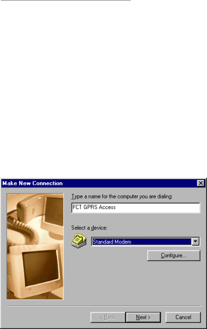
2) Double-click on ‘Make New Connection’ so that the
wizard starts. Type a name for the connection and select
the installed analog modem from your computer, then click
on ‘Next’.
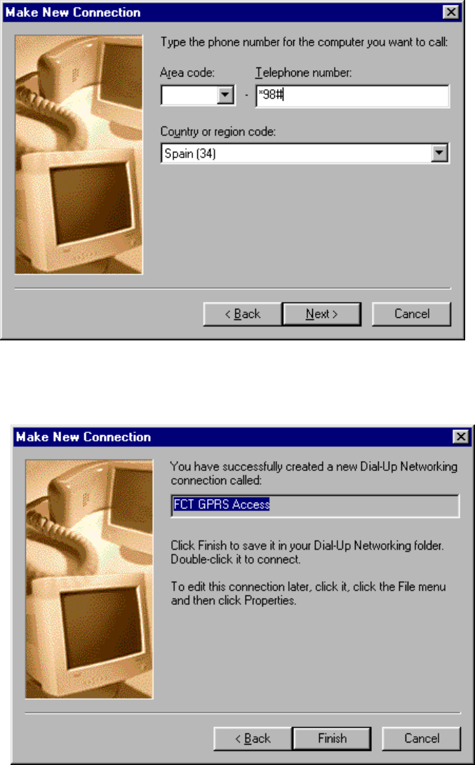
3) In the ‘Telephone number:’ field enter: *98#, then click
‘Next’.
46/70
4) Click on ‘Finish’.
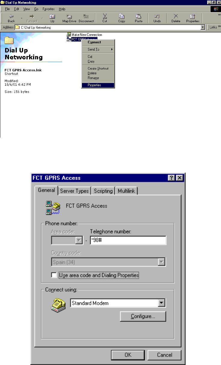
5) In the ‘Dial-Up Networking’ folder, right-click on the
created connection and select ‘Properties’.
47/70
6) In the ‘General’ tab, turn off ‘Use area code and Dialing
Properties’.
48/70
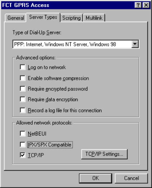
7) In the ‘Server Types’ tab:
– ‘Type of Dial-Up Server’: select ‘PPP: Internet, Windows
NT, Windows 98’ from the list.
– Check that ‘Advanced options’ and ‘Allowed network
protocols’ are filled in as shown below:
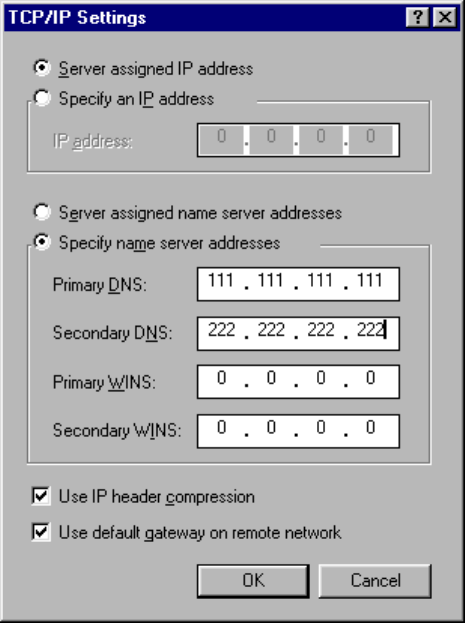
8) Push the ‘TCP/IP Settings…’ button.
– ‘Server assigned IP address’ must be checked.
– ‘Server assigned name server addresses’ must be set if the
network operator requires it. If the network operator
provides DNS addresses, then these must be added once
‘Specify name server addresses’ is marked. (Example
shown in figure below with primary and secondary DNS
addresses provided by operator being 111.111.111.111 and
222.222.222.222)
– ‘Use IP header compression’ optional.
49/70
– ‘Use default gateway on remote network’ turned on.
9) Click ‘OK’ all the way to update the configuration.
You have now installed the GPRS connection. To connect to
the GPRS network, follow steps 1 to 3:
1) Go to ‘My Computer’-> Dial-Up Networking’ and open
the previously configured connection.
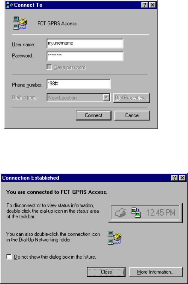
2) Type the user name and password provided by your
network operator and verify that the telephone number is
*98#. Then press ‘Connect’.
50/70
3) Once you are connected, you may use your connection as
an ordinary Internet connection.
Note: if your network operator has provided you with a Proxy
Address, you should configure your Web browser (Internet
Explorer, Netscape, etc.) accordingly.
15.2 WINDOWS NT GPRS SET-UP
Warning!: your PC must have the Remote Access Service
and the TCP/IP protocol installed within the network
components. You can check this in ‘Start->Settings-
51/70
>Control Panel’ and double clicking on ‘Network’. If not,
these components have to be previously added from your
Windows installation disk.
To configure your GPRS connection under a Windows NT PC,
follow steps 1 to 8:
1) Go to ‘My Computer’ and double-click ‘Dial-Up
Networking’.
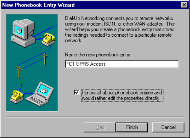
2) If there are no previously configured connections, the
following wizard will be showed up. Type a name for the
connection and tick ‘I know all about phonebook entries
and would rather edit the properties directly’. Then click
on ‘Finish’; edit properties of this new connection and go
to step 4) to continue with the configuration.
3) Instead of the wizard window, the following window might
come up. In this case, push ‘New…’ button.
52/70
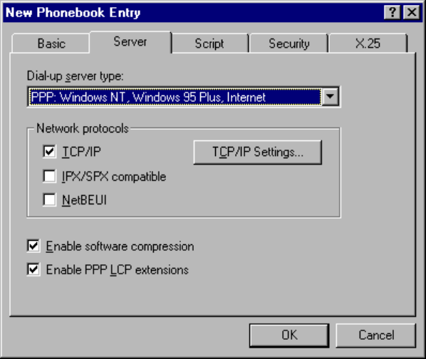
4) Within the ‘Basic’ tab, type a name for the connection in
the ‘Entry name’ field. In the ‘Dial using’ field select the
analog modem already installed on your PC.
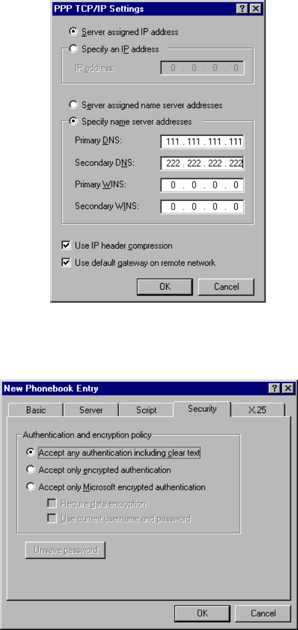
5) In the ‘Server’ tab select ‘PPP: Windows NT, Windows 95
Plus, Internet’ from the ‘Dial-up server type’ list. Assure
‘TCP/IP’ is the only ticked protocol within the ‘Network
protocols’ box.
53/70
6) Push the ‘TCP/IP Settings…’ button.
– ‘Server assigned IP address’ must be checked.
– ‘Server assigned name server addresses’ must be set if
network operator requires it. If the network operator
provides DNS addresses, then these must be added once
‘Specify name server addresses’ is marked.(Example
shown in figure below with primary and secondary DNS
addresses provided by operator being 111.111.111.111 and
222.222.222.222)
– ‘Use IP header compression’ optional.
– ‘Use default gateway on remote network’ turned on.
54/70
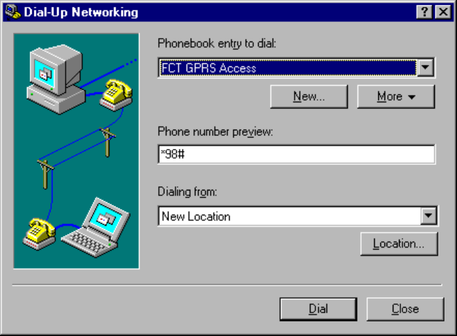
7) Press ‘OK’ and go to the ‘Security’ tab. Select ‘Accept
any authentication including clear text’.
55/70
8) Click ‘OK’ all the way to update the configuration.
You have now installed the GPRS connection. To connect to
the GPRS network, follow steps 1 to 3:
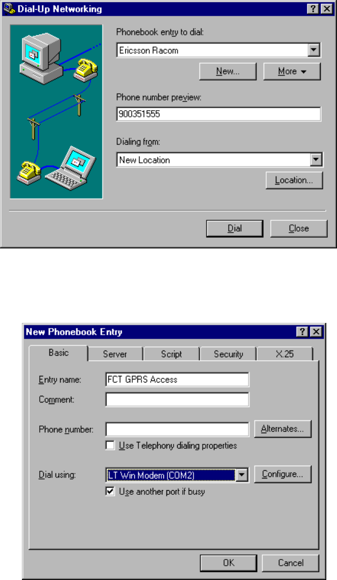
1) Go to ‘My Computer -> Dial-Up Networking’ and select
the Dial-Up Networking connection previously configured.
Verify that the telephone number is *98#. Then press
‘Dial’.
2) Type the user name and password provided by your
network operator. If a ‘Domain’ field is present, then leave
it blank.
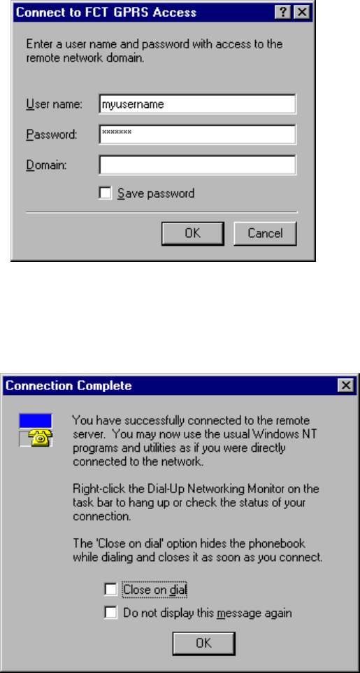
56/70
3) Once you are connected, you may use your connection as
an ordinary Internet connection.
Note: if your network operator has provided you with a Proxy
Address, you should configure your Web browser (Internet
Explorer, Netscape, etc.) accordingly.

57/70
16 SAFE AND EFFICIENT USE
Note: please read this information before using your FCT.
Save this user guide since it contains important safety
information and operating instructions.
16.1 PRODUCT CARE
• Do not expose your FCT to liquid or moisture.
• Do not expose your FCT to extreme high or low
temperatures.
• Do not expose your FCT to lit candles, cigarettes, or
cigars, or to open flames etc.
• Do not attempt to disassemble your FCT, a broken
warranty seal will void the warranty. The product does not
contain consumer serviceable components. Only Ericsson
Service Points or Certified Service Centres should perform
service.
• Do not use any accessories other than Ericsson originals
with the exception of products approved by Bluetooth
Qualification Review Board. Use of non-Ericsson original
accessories may result in loss of performance, damage to
the product, fire, electric shock or injury. The warranty
does not cover product failures that have been caused by
use of non-Ericsson original accessories.
• Treat your product with care, keep it in a clean and
dust-free place.
16.2 ANTENNA CARE
• Use only an antenna that has been specifically designed for
your FCT. Use of unauthorized antennas, modifications, or
attachments could damage the FCT and may violate the
appropriate regulations, causing loss of performance and
radio frequency (RF) energy above the recommended
limits.
58/70
• Do not hold or touch the antenna when the FCT is in use.
Holding or touching the antenna affects call quality.
• Do not use the FCT if the antenna or antenna cable is
damaged or missing.
• Do not place the telephone cord or the power supply cord
on or near the FCT antenna or antenna cable.
• Do not cover or place an obstruction on or around the
antenna.
16.3 RADIO FREQUENCY ENERGY
Your FCT is a radio transmitter and receiver. When the FCT is
turned on, it receives and transmits radio frequency (RF)
energy. The system that handles your call when you are using
your FCT controls the power level at which your FCT
transmits.
All Ericsson terminals are designed to not exceed the limits for
exposure to RF energy set by national authorities and
international health agencies.
SAR (Specific Absorption Rate) measurements are usually
performed for products that are normally used at the ear. As
the FCT is not to be used close to the human body, as it is at
least 20 cm apart from the telephone device (See installation
instructions), SAR measurements are not applicable to the
FCT.
16.4 ELECTRONIC DEVICES
Most modern electronic equipment, for example equipment in
hospitals and cars, is shielded from RF energy. However,
certain electronic equipment is not, and so Radio Frequency
(RF) energy from the FCT terminal may affect some electronic
equipment, therefore:
• Do not use your FCT near medical equipment without
requesting permission.
• Do no use your FCT in aircrafts.
59/70
• Pacemaker patients should be aware that the use of an FCT
very close to a pacemaker might cause the device to
malfunction.
• Some hearing aids might be disturbed if placed very near
the FCT.
Multiple electrical devices connected to the AC power outlet
that is used by the FCT terminal may generate excessive
interference to the FCT terminal.
16.5 POTENTIALLY EXPLOSIVE ATMOSPHERES
Do not use the FCT near a gas leak. Use a telephone away
from the area of the suspected gas leak to immediately report
it.
Turn off the FCT in areas with a potentially explosive
atmosphere, for example: gas stations, below deck on boats,
fuels or chemical transfer or storage facilities, and areas where
the air contains chemical or particles, such as grain, dust or
metal powders. It is rare, but your FCT or its accessories could
generate sparks.
Do not transport or store flammable gas, liquid or explosives in
the areas where the FCT is installed.
16.6 POWER SUPPLY
• Ensure that your AC power outlet is adequately grounded.
• Connect the power supply cord only to the AC power
outlet that meet the specifications marked on the FCT
power supply.
• Never alter the AC power cord or plug. If necessary have
the correct outlet installed by a qualified electrician or call
your service provider for assistance.
• To reduce risk of damage to the electric cord, remove it
from the outlet by holding onto the AC adapter rather than
the cord.
60/70
• Make sure the cord is positioned so that it will not be
stepped on, tripped over or otherwise subjected to damage
or stress.
16.7 CHILDREN
DO NOT ALLOW CHILDREN TO PLAY WITH YOUR
FCT SINCE IT CONTAINS SMALL PARTS THAT COULD
BECOME DETACHED AND CREATE A CHOKING
HAZARD.
16.8 DISPOSING OF THE PRODUCT
The product should never be placed in municipal waste. Please
check local regulations for disposal of electronic products.
16.9 BATTERY INFORMATION
If you use the battery back-up function of the FCT, please take
into account the following information:
Lead Battery
• Before installing the battery in its compartment, be sure to
connect the battery cable properly: do not connect the
positive terminal of the battery cable to the negative
terminal on the battery.
• Make sure to connect the FCT power supply first, before
you connect the battery to the FCT.
• The FCT will automatically recharge the lead battery
• The first time the battery is used, it is recommended that
you charge it for 3 hours if you intend to power the FCT
from the battery only.
A rechargeable battery has a long service life if treated
properly.
61/70
Warning!: when a battery is not installed or is connected to
an FCT that is switched off, it should be recharged during 24
hours every 6 months.
• Do not expose the battery to extreme temperatures, never
above +60°C. For maximum battery capacity, use the
battery in room temperature.
• Do not let the metal contacts on the battery touch another
metal object. This could short-circuit and damage the
battery.
• Do not expose the battery to open flames. This could cause
the battery to explode.
• Do not expose the battery to liquid.
• Do not allow the battery to be put into the mouth. Battery
electrolytes may be toxic if swallowed.
• Do not puncture or burn the battery. The battery contains
corrosive liquids and materials.
• If the battery leaks and the liquid inside spills on the skin
or clothing, immediately wash it off with plenty of clean
water. If the liquid splashes into eyes, immediately flush
the eyes with plenty of clean water and consult a doctor.
AA batteries
• Use only AA-1.5V alkaline batteries with the FCT battery
holder accessory. See “FCT accessories” on page 41
• If you use rechargeable AA batteries, these will need to be
recharged using an external charger, never in the FCT.
16.10 DISPOSING OF THE BATTERY
The battery should never be placed in municipal waste. Please
check local regulations for disposal of batteries.
16.11 MOVING OR STORING THE FCT

62/70
Turn off the FCT by disconnecting the power supply as well as
the battery (if it is installed).
If you are transporting the FCT on an aircraft, you will be
asked to remove the battery from the unit. For updated
information about the transportation and use of wireless
communication equipment, contact the appropriate local and
national regulatory agency or your service provider.
16.12 ACCESSING THE BATTERY COMPARTMENT
This label appears under the battery
compartment indicating that the FCT
should always be switched off before
attempting to access the battery
compartment
Disposing of the Battery
Disposing of the Product
Emergency Calls
Battery Information
Explosive Atmospheres

63/70
17 LIMITED WARRANTY
17.1 LIMITED WARRANTY CONDITIONS
Thank you for purchasing this Ericsson Product. To get the
maximum use out of your new product, we recommend that
you follow a few simple steps:
• Read the Guidelines for safe and efficient use.
• Read all of the terms and conditions of the Ericsson
Warranty listed below.
• Save your original receipt, which is necessary for warranty
repair claims. Should your Ericsson Product need warranty
service, you should return it to the dealer from whom it was
purchased or contact your local Ericsson helpdesk for further
information.
17.2 ERICSSON WARRANTY
Ericsson warrants this Product to be free from defects in
material and workmanship at the time of its original purchase
by a customer, and for a subsequent period of one (1) year.
All accessories for the Product are covered by a warranty
period of one (1) year from the date of original purchase by a
customer.
17.3 WHAT ERICSSON WILL DO
If, during the warranty period, this Product fails to operate
under normal use and service, due to improper materials or
workmanship, Ericsson subsidiaries, authorized distributors, or
authorized service partners will, at their own option, either
repair or replace the Product in accordance with the terms and
conditions stipulated herein.
For efficiency purposes, Customers are reminded that should
their Ericsson Product need warranty service, they return it to
the dealer from which it was purchased or call their local
Ericsson helpdesk for further information on warranty claims.
64/70
17.4 CONDITIONS
1. The warranty given herein is only valid if the original
receipt issued by the dealer to the original purchaser,
specifying the date of purchase and serial number, is
presented along with the Product to be repaired or
replaced. Warranty service may be refused if this
information is not available or has been removed or
changed after the original purchaser of the Product from
the dealer.
2. Any repair or replaced Product will be warranted for the
remainder of the original warranty period. Repair or
replacement may be via functionally equivalent
reconditioned units. Replaced faulty parts or components
will become the property of Ericsson.
3. This warranty does not cover any failure of the Product due
to normal wear and tear, misuse, including but not limited
to use in other than a normal and customary manner, in
accordance with Ericsson’s instructions for use and
maintenance of the Product, accident, modification or
adjustment, acts of God, improper ventilation, or damage
resulting from liquid.
4. This warranty does not cover product failures due to repair
installations, modifications or improper service performed
by a non-Ericsson authorized service workshop, opening of
the Product by a non-Ericsson authorized person or use of
non-Ericsson original accessories.
5. Batteries are not covered by this warranty.
6. Tampering with any of the seals on the Product will void
this warranty.
7. THERE ARE NO OTHER EXPRESS WARRANTIES,
WHETHER WRITTEN OR ORAL, OTHER THAN THIS
PRINTED LIMITED WARRANTY. ALL IMPLIED
WARRANTIES, INCLUDING WITHOUT LIMITATION
IMPLIED WARRANTIES OF MERCHANTABILITY
OR FITNESS FOR A PARTICULAR PURPOSE, ARE
LIMITED TO THE DURATION OF THIS LIMITED
WARRANTY. IN NO EVENT WILL ERICSSON BE
LIABLE FOR LOSS OF PROFITS, COMMERCIAL
LOSS, INCIDENTAL OR CONSEQUENTIAL
DAMAGES OF ANY NATURE, TO THE FULL
65/70
EXTENT THOSE DAMAGES CAN BE DISCLAIMED
BY LAW.
Some countries do not allow for the exclusion or limitation of
loss of profits, commercial loss, incidental or consequential
damages, or limitation of the duration of implied warranties, so
the preceding limitations or exclusions may not be applicable
in certain cases. This warranty gives specific legal rights, and
depending on the country, other rights may be available as
well.
International

66/70
18 REGULATORY INFORMATION
Declaration of Conformity
We, Ericsson Radio Systems AB of
Kistagången 26, Kista
S-16480 Stockholm, Sweden
declare under our sole responsibility that our product
Ericsson type 0130101-BV
and in combination with our accessories, to which this
declaration relates is in conformity with the appropriate
standards 3GPP TS 51.010-1, EN 301 489-7 and EN 60950,
following the provisions of, Radio Equipment and
Telecommunication Equipment directive 99/5/EC with
requirements covering EMC directive 89/336/EEC, and Low
voltage directive 73/23/EEC.
Kista November 15, 2001
Place & date of issue
____________________________
Birger Kjellander, General Manager FCT
We fulfil the requirements of the R&TTE Directive (99/5/EC).
FCC Statement
Before a phone is available for sale to the public, it must be
tested and certified to the FCC that it does not exceed the limit
established by the government-adopted requirement for safe
exposure.
Nevertheless, for mobile devices where the radiating structure
is located more than 20 cm away from the user and the EIRP
(radiating power) is lower than 3 Watts for transmitting
frequencies higher than 1.5 GHz, SAR (Specific Absorption
Rate) measurements are not required.

67/70
This device complies with Part 15 of the FCC rules. Operation
is subject to the following two conditions: (1) This device may
not cause harmful interference, and (2) This device must
accept any interference received, including interference that
may cause undesired operation.

68/70
19 DEFINITIONS
The following definitions are supplied in order to better
understand certain concepts included in this manual:
Switch-on: power up the FCT by connecting the AC power
supply or a charged battery.
Switch-off: power down the FCT by disconnecting the AC
power supply or removing the battery.
Fixed Line Devices: any analog devices that can be connected
to the analog fixed line :
Fixed Telephones- ordinary telephones for the fixed line
G3 Faxes- ordinary fax machines available on the market
CLI devices- ordinary displays or telephones equipped
with displays that show the caller number for incoming
calls.
V.90 modems- standard modems for PCs used to make
data connections (Internet) over the ordinary fixed line.
Telephone Line: this is the line provided by the FCT (RJ11
connector) that behaves in the same way as the ordinary fixed
line.
Telephone Line Wiring: this is the cable layout that has to be
available in order to distribute telephone lines within a house
or office.
GPRS: General Packed Radio Service. This is a technology
for data communications that is ideal for e-mail or Internet
access as it provides a high speed “always online” connection.
This means that, although you are always attached to the
network, you only pay for the amount of data that you really
transmit.
PBX: Public Branch eXchange. It is a telephone system within
an enterprise that switches calls between enterprise users on
local lines while allowing all users to share a certain number of
external phone lines.
SIM card: this is the card provided by your network operator
that you need to insert in your GSM terminal in order to make
69/70
and receive calls. It contains all the information from your
subscription characteristics.
