Escatronic ESCADISTANCE ESCA DISTANCE US/CA User Manual Testreport ETS 300 335
Escatronic GmbH ESCA DISTANCE US/CA Testreport ETS 300 335
Users Manual

Test report no. 18011127 Page 1 of 1
EUT: ESCA DISTANCE
US/CA
FCC ID: 2ANW5-
ESCADISTANCE
FCC Title 47 CFR Part 15
Date of issue: 2018-01-05
Date: 2017-09-07
Created: P9 Controlled: P4 Released: P1
Vers. no. 1.17
m. dudde hochfrequenz-technik
GmbH & Co. KG
Rottland 5a
51429 Bergisch Gladbach/ Germany
Tel: +49 2207-96890
Fax +49 2207-968920
Annex acc. to FCC Title 47 CFR Part 15
relating to
ESCATRONIC GmbH
ESCA DISTANCE US/CA
Annex no. 5
User Manual
Functional Description
Title 47 - Telecommunication
Part 15 - Radio Frequency Devices
Subpart C – Intentional Radiators
ANSI C63.4-2014
ANSI C63.10-2013

ESCA DISTANCE S3
Safety for Escalators
RADAR - Sensor to be used on escalators and walkways
certified due to performance level “d” according to
EN ISO 13849-1:2008 and certified according to EN115-1:2008
E 11.17
DISTANCE S3 Version.1.0EN Revisionsdatum: 09.11.2017 Erstellt: MRU Freigegeben: SPA
ESCATRONIC GmbH, D-31157 Sarstedt, Ludwig Erhard Ring 24, Tel. +49 5066 699 990, Fax +49 5066 699 99 30 -1-

ESCA DISTANCE S3
Safety for Escalators
Table of contents
1. General description...........................................................................................................................3
2. Versions............................................................................................................................................3
3. Technical data...................................................................................................................................3
3.1 General.......................................................................................................................................3
3.2 Sensor.........................................................................................................................................4
3.3 Certification...............................................................................................................................4
3.4 Connection Options...................................................................................................................5
4. Installation........................................................................................................................................5
4.1 Mounting position......................................................................................................................5
4.2 Prescribed check of mounting position......................................................................................5
5. Output signal lines............................................................................................................................6
6. Fault tracking....................................................................................................................................6
6.1 Detection of malfunction...........................................................................................................7
6.2 Indication of errors or faults......................................................................................................7
7. DECLARATION OF CONFORMITY.............................................................................................8
8. Certificate.........................................................................................................................................9
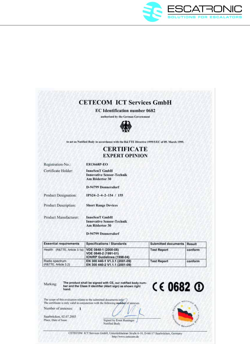
8.1 RADAR Module........................................................................................................................9
8.2 TÜV Certificate........................................................................................................................11
8.3. FCC.........................................................................................................................................13
DISTANCE S3 Version.1.0EN Revisionsdatum: 09.11.2017 Erstellt: MRU Freigegeben: SPA
ESCATRONIC GmbH, D-31157 Sarstedt, Ludwig Erhard Ring 24, Tel. +49 5066 699 990, Fax +49 5066 699 99 30 -2-
ESCA DISTANCE S3
Safety for Escalators
1. General description
The Radar Sensor DISTANCE S3 has been designed to be used as contact less acting security device for
moving staircases (escalators). The sensor is acting as a Doppler-radar intrinsically safe according to
Performance Level d EN ISO13849-1:2008. His capture range covers the entrance area of the escalator
above the contact plate area. It detects slow moving passengers as well as passenger with low reflecting
surface to start-up the escalator according to EN115-1:2008.
2. Versions
The Radar-Sensor DISTANCE S3 is available in different Versions. They have different detection ranges of
the Sensor. There are also sensors that will only detect approaching persons or both approaching and
departing persons.
There are 2 different versions of outputs availlable:
V1 has one potential free Optocoupler output as opener.
V2 has two active 24V Outputs, which are phase-shifted 180°.
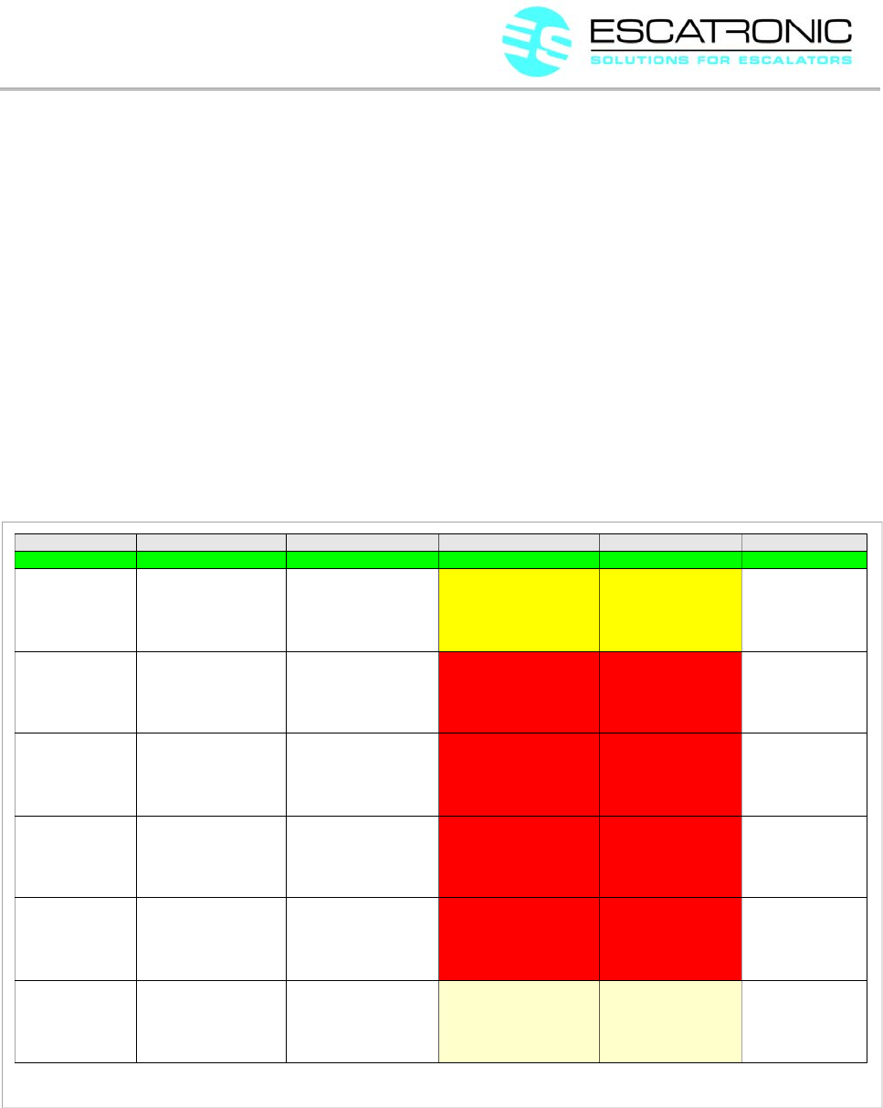
Als versions are in the following table:
Name Opening angel Output Range Approaching/Departing
DISTANCE S3-V1 70°H , 36°V V1 2,5 - 2,7m Approaching only
DISTANCE S3-V2 70°H , 36°V V2 2,5 - 2,7m Approaching only
DISTANCE S3-V2-120 70°H , 36°V V2 1,2 - 1,3m Approaching only
DISTANCE S3-V2-120-BD 70°H , 36°V V2 1,2 - 1,3m Approaching & Departing
3. Technical data
3.1 General
Supply voltage: 24V...28V
Current consumption: max. 50mA
Signal output: potential free optocoupler (OC)
Contact type: normally closed (opener)
Alternative contact type: 2 phase output, 180° phase shift.
DISTANCE S3 Version.1.0EN Revisionsdatum: 09.11.2017 Erstellt: MRU Freigegeben: SPA
ESCATRONIC GmbH, D-31157 Sarstedt, Ludwig Erhard Ring 24, Tel. +49 5066 699 990, Fax +49 5066 699 99 30 -3-

ESCA DISTANCE S3
Safety for Escalators
Switching current: max. 50mA
Response time: ca.100ms
Max. voltage level: 70VDC
min. duty cycle (open contact): 0,5s
Dimensions (H*W*D) 46 x 56 x 20 mm
Temp. range: -20°C....+80°C
Protection class: IP67
3.2 Sensor
Transmitter frequency: 24,075...24,0175 GHz
Max. RF output power: 100mW
Angle of beam horizontal: 70°
Angle of beam vertical: 32°
Sensitivity range: 2,5...2,7m pre-set
Moving sense: towards sensor or toward and from sensor
Response time: < 0,1m/s
3.3 Certification
EN115-1:2008
EN13849-1:2008
EN12015
EN12016:2004
2006/42/EG from 29.12.2009
2011/65/EU ROHS
2014/35/EU
2014/30/EU
Radio spectrum
ETSI EN300400-1V1.3.1 (2001-09)
ETSI EN300440-2V1.1.1. (2001-09)
Health
VDE 0848 (08/2000) Part1
VDE 0848 (01/1991) Part 2
ICNIRP Guidelines (04/1998)
DISTANCE S3 Version.1.0EN Revisionsdatum: 09.11.2017 Erstellt: MRU Freigegeben: SPA
ESCATRONIC GmbH, D-31157 Sarstedt, Ludwig Erhard Ring 24, Tel. +49 5066 699 990, Fax +49 5066 699 99 30 -4-

ESCA DISTANCE S3
Safety for Escalators
3.4 Connection Options
Cable 4 x 0,25mm², length 0,5m, M12 connector assembly
Pin assignment Dual-Different output (version 1):
Pin 1 +24VDC brown
Pin 2 Output 1 OC PNP white, 180° phase shift output compared to Pin 4.
Pin 3 GND blue
Pin 4 Output 2 OC PNP black, security controlled output
Pin assignment Single-Ended potential free output (Version 2):
Pin 1 +24VDC brown
Pin 2 Output OC out - white
Pin 3 GND blue
Pin 4 Output OC out + black
4. Installation
4.1 Mounting position
The recommended locations to install the sensor into the escalator:
- below of handrail entrance point
- into the balustrade base
- at the area of the contact-mat inside a protective housing
4.2 Prescribed check of mounting position
For each type of escalator it is once required to determine and document the selected mounting position.
It has be assured to cover the entrance area of the escalator by the sensor range and to make sure this
range/area can not be bypassed by any passenger. This procedure will secure a save start of the escalator.
The sensor should be protected from covering it by any metal parts.
To test the entrance area a metal sphere of 18cm diameter should be used to simulate repeatable an
approaching passenger.
The test using the metal sphere begins at a distance of 2.5m rolling the sphere slowly in direction of the
DISTANCE S3 Version.1.0EN Revisionsdatum: 09.11.2017 Erstellt: MRU Freigegeben: SPA
ESCATRONIC GmbH, D-31157 Sarstedt, Ludwig Erhard Ring 24, Tel. +49 5066 699 990, Fax +49 5066 699 99 30 -5-

ESCA DISTANCE S3
Safety for Escalators
spirketing. The radar sensor has to activate the escalator in a distance of 1.6m from the spirketing. This
procedure has to be repeated for all possible passenger routes into the entrance area. If the sensor doesn't
recognise the movement of the sphere on a certain route, the mounting position of the radar sensor has to
be modified accordingly.
The escalator manufacturer or the service/refurbishment company is responsible for the correct check of the
sensor accordingly to the procedure shown above.
The radar sensor manufacture can not be held responsible for any loss or damage based on an inaccurate
selected mounting position or ambiance or coverage of the radar sensor.
5. Output signal lines
The output lines are different due to the configuration of the radar sensor module (please refer to
chapter 3.4). If a movement is detected by the radar sensor the output level is changed for about 0.5
seconds. The meaning for the possible status of the two different module versions are shown in table 1
below:
6. Fault tracking
The radar sensor undergo periodic repeating internal self tests while he is in operation. The time interval for
this test are max 10 seconds. During these test cycles the radar receiver, as well as the internal controller
memory and the output lines are checked for error-free functionality. Some of the output errors can only be
DISTANCE S3 Version.1.0EN Revisionsdatum: 09.11.2017 Erstellt: MRU Freigegeben: SPA
ESCATRONIC GmbH, D-31157 Sarstedt, Ludwig Erhard Ring 24, Tel. +49 5066 699 990, Fax +49 5066 699 99 30 -6-
Version 1 (Dual-difference output) Version 2 (Single-ended potential free output)
Output 1 output 2 Meaning Output Meaning
low high No movement detected,
module in operation
low No movement detected,
module in operation
high low Movement detected,
module in operation
high Movement detected,
If permanent: Fault detected inside
the module
low low Fault detected
high high Not valid
Table 1: Possible status of output lines
ESCA DISTANCE S3
Safety for Escalators
detected when the output power is changed.
6.1 Detection of malfunction
If an internal malfunction is detected during these tests, the output of the radar sensor is permanently
disabled. It is impossible to reactivate the radar sensor again.
A cable break from the radar sensor to the escalator control results in an open output signal which forces the
escalator control to keep continuous operation for the current direction.
The status of the output signal lines after detection of a malfunction are described in chapter 4.
6.2 Indication of errors or faults
A LED points out the module status. The LED is visible on the side of the housing.
Possible faults are described in table 2:
DISTANCE S3 Version.1.0EN Revisionsdatum: 09.11.2017 Erstellt: MRU Freigegeben: SPA
ESCATRONIC GmbH, D-31157 Sarstedt, Ludwig Erhard Ring 24, Tel. +49 5066 699 990, Fax +49 5066 699 99 30 -7-
Table 2: Indication of errors
Name Diagnostic Interval of execution Fault impact Resetting Fault signal
No fault The green LED is on
Sensor fault Repeating the test
No successful restart
Program fault No successful restart
Output fault No successful restart
Watchdog fault
Current fault Repeat the tests
The radar modul is
checked after power-up for
a specific step-response-
function.
every xx seconds Put the module out of
operation (secure situation
due to open output lines)
The red and the green
LED are flashing.
„Galpat“ fault The internal memory will
be tested using walking
„1“ and “0“ for error-free
operation.
every xx seconds Put the module out of
operation (secure situation
due to open output lines)
The red LED will be
on all the time.
Specific patterns are
stored into the internal
memory and tested by
comparison of the
checksum
every xx seconds Put the module out of
operation (secure situation
due to open output lines)
The red LED will be
on all the time
The opto-coupler on the
output lines is tested for
error free operation (open)
If it is required to open the
output line and during
power-up, if the current
test was successful
Put the module out of
operation (secure situation
due to open output lines)
The red LED will show
the following
sequence: short-
short-long
The watch-dog and the
opto-coupler are tested for
error free operation (open)
If it is required to open the
output lines and while
power-up if the current test
was successful
Put the module out of
operation (secure situation
due to open output lines)
Kein erneutes Anlaufen The red LED will show
the following
sequence: long-long-
short
The current on the closed
output lines is read back.
If it is not required to open
the signal line and after
power-up.
Don't take module out of
operation. Continue the
tests, eventually cable
break or output signal line
not connected
The green LED is
flashing

ESCA DISTANCE S3
Safety for Escalators
7. DECLARATION OF CONFORMITY
EG-Konformitätserklärung
Im Sinne der EG-Richtlinie Maschinen 2006/42/EG
Hiermit erklären wir, dass die Bauart der folgenden Geräte
DISTANCE S3
den einschägigen Bestimmungen entspricht.
Angewendete harmonisierte Normen:
EN 62061:2005+A1:2012
EN12016:2004+A1:2008
EN115-1:2008+A1:2010 Abschnitt 5.12.2.4.2
Sonstige angewendete Normen:
EN12015:2004
2006/42/EG from 29.12.2009
2011/65/EU ROHS
2014/35/EU
2014/30/EU
EN13849-1:2008
siehe Baumusterprüfung ab Seite Fehler: Referenz nicht gefunden
Gemeldete Stelle nach Richtlinie 2006/42/EG:
TÜV NORD CERT GmbH
Kennnummer: 0044
Langemarckstrasse 20
45141 Essen
Unterlagenbevollmächtigte: Anke Schreiber
EG – Baumusterbescheinigungs-Nr.: 44 205 XXXXXX
ESCATRONIC GmbH
Ludwig Erhard Ring 24
D-31157 Sarstedt
Laatzen 28.07.2014
DISTANCE S3 Version.1.0EN Revisionsdatum: 09.11.2017 Erstellt: MRU Freigegeben: SPA
ESCATRONIC GmbH, D-31157 Sarstedt, Ludwig Erhard Ring 24, Tel. +49 5066 699 990, Fax +49 5066 699 99 30 -8-
ESCA DISTANCE S3
Safety for Escalators
Anke Schreiber
Geschäftsführerin
8. Certificate
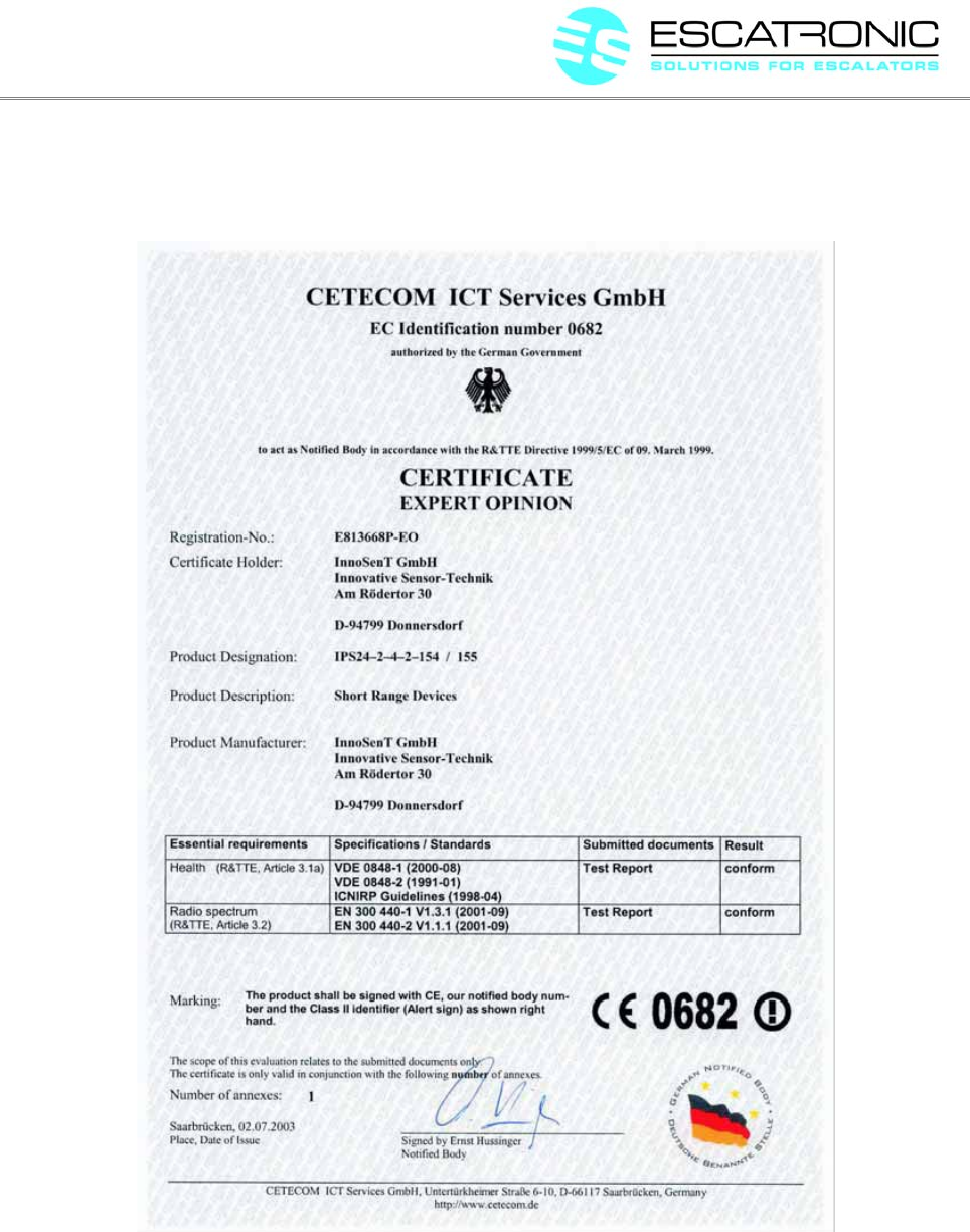
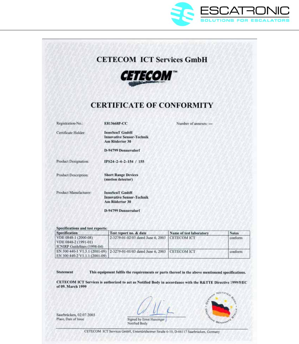
8.1 RADAR Module
DISTANCE S3 Version.1.0EN Revisionsdatum: 09.11.2017 Erstellt: MRU Freigegeben: SPA
ESCATRONIC GmbH, D-31157 Sarstedt, Ludwig Erhard Ring 24, Tel. +49 5066 699 990, Fax +49 5066 699 99 30 -9-

ESCA DISTANCE S3
Safety for Escalators
DISTANCE S3 Version.1.0EN Revisionsdatum: 09.11.2017 Erstellt: MRU Freigegeben: SPA
ESCATRONIC GmbH, D-31157 Sarstedt, Ludwig Erhard Ring 24, Tel. +49 5066 699 990, Fax +49 5066 699 99 30 -10-
ESCA DISTANCE S3
Safety for Escalators
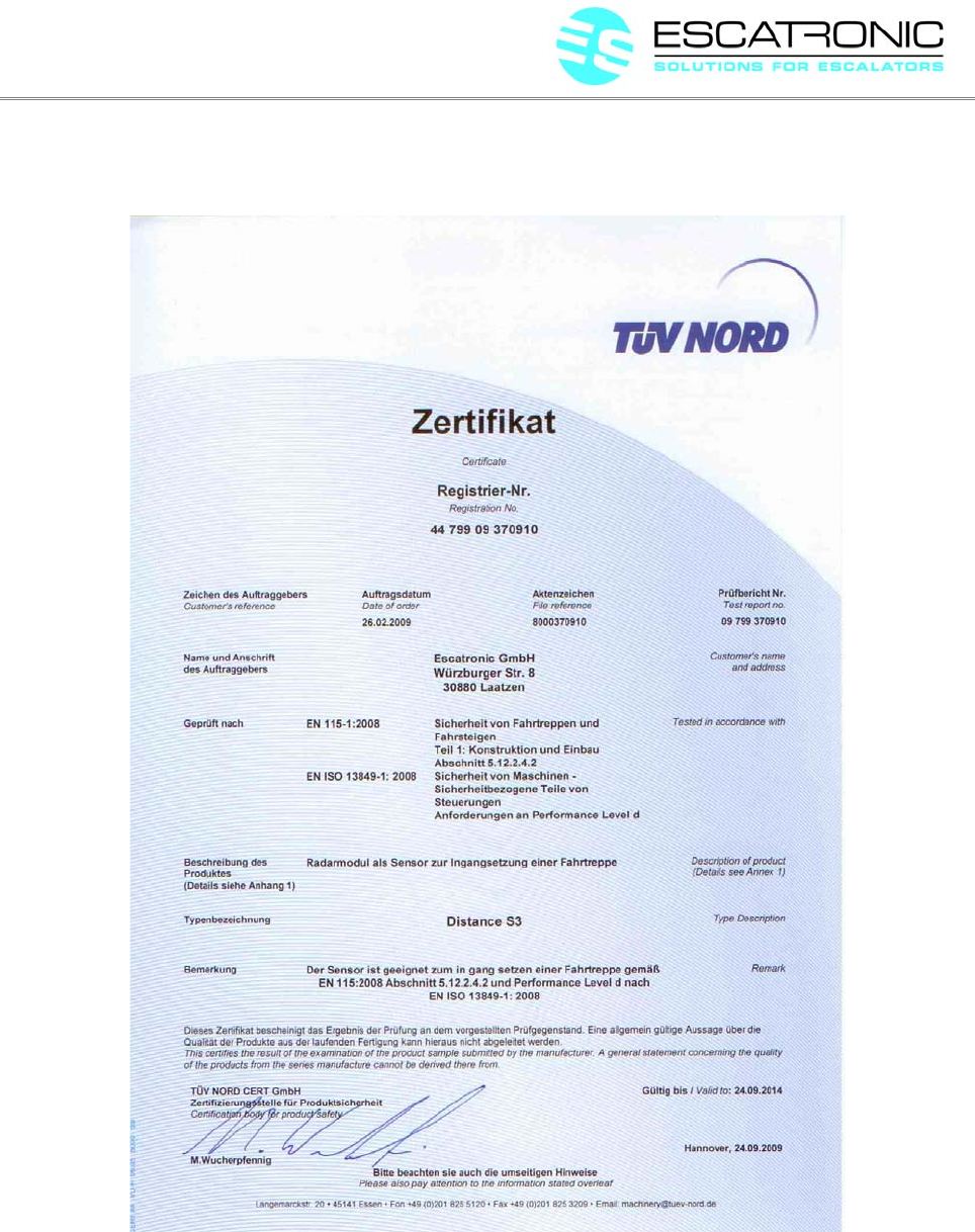
8.2 TÜV Certificate
DISTANCE S3 Version.1.0EN Revisionsdatum: 09.11.2017 Erstellt: MRU Freigegeben: SPA
ESCATRONIC GmbH, D-31157 Sarstedt, Ludwig Erhard Ring 24, Tel. +49 5066 699 990, Fax +49 5066 699 99 30 -11-
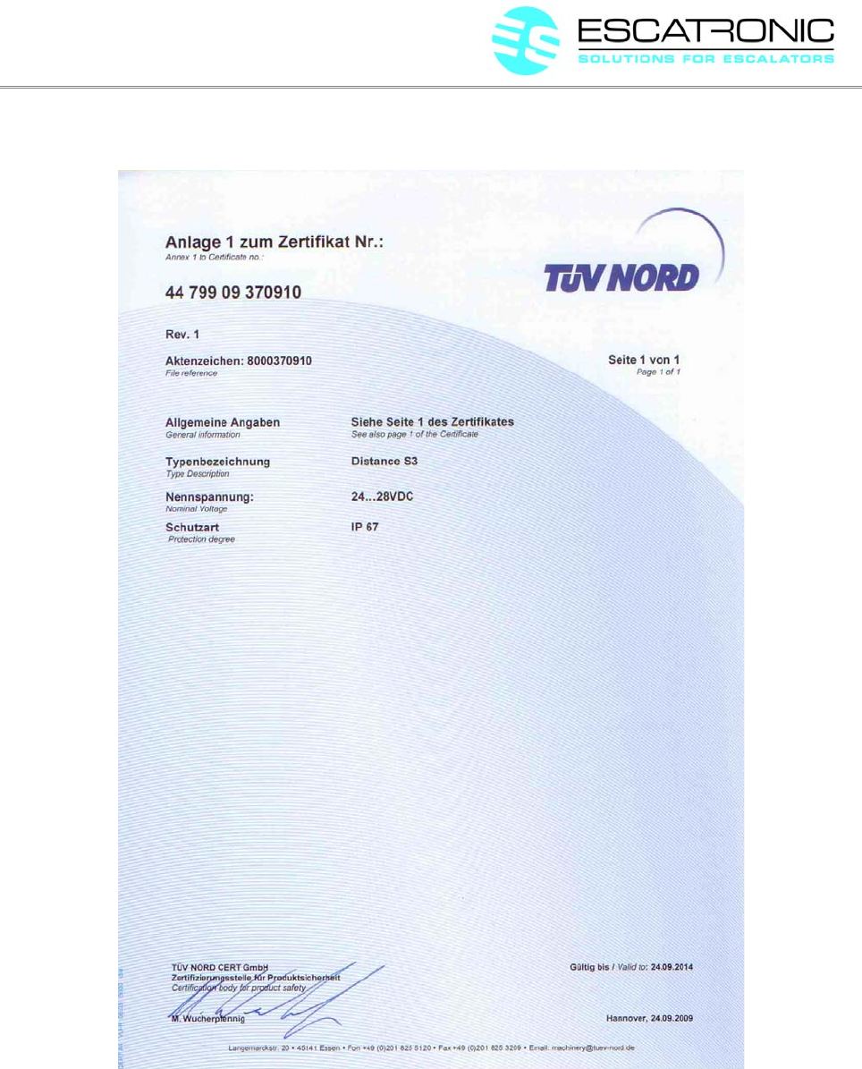
ESCA DISTANCE S3
Safety for Escalators
DISTANCE S3 Version.1.0EN Revisionsdatum: 09.11.2017 Erstellt: MRU Freigegeben: SPA
ESCATRONIC GmbH, D-31157 Sarstedt, Ludwig Erhard Ring 24, Tel. +49 5066 699 990, Fax +49 5066 699 99 30 -12-

ESCA DISTANCE S3
Safety for Escalators
8.3. FCC
FCC ID: 2ANWS-ESCADISTANCE
This device complies with part 15 of the FCC Rules. Operation is subject to the following
two conditions: This device may not cause harmful interference, and this device must
accept any interference received, including interference that may cause undesired
operation.
DISTANCE S3 Version.1.0EN Revisionsdatum: 09.11.2017 Erstellt: MRU Freigegeben: SPA
ESCATRONIC GmbH, D-31157 Sarstedt, Ludwig Erhard Ring 24, Tel. +49 5066 699 990, Fax +49 5066 699 99 30 -13-

ESCA DISTANCE 2S
Safety for Escalators
RADAR - Sensor to be used on escalators and walkways
according to EN115-1:2008
E 11.17
DISTANCE S3 Version.1.0EN Revisionsdatum: 09.11.2017 Erstellt: MRU Freigegeben: SPA
ESCATRONIC GmbH, D-31157 Sarstedt, Ludwig Erhard Ring 24, Tel. +49 5066 699 990, Fax +49 5066 699 99 30 -1-

ESCA DISTANCE 2S
Safety for Escalators
Table of contents
1. General description...........................................................................................................................3
2. Function............................................................................................................................................3
3. Technical data...................................................................................................................................3
3.1..........................................................................................................................................General
.........................................................................................................................................................3
3.2............................................................................................................................................Sensor
.........................................................................................................................................................4
3.3..................................................................................................................................Certification
.........................................................................................................................................................4
3.4...................................................................................................................Connection - versions
.........................................................................................................................................................4
4. Installation........................................................................................................................................5
4.1 Mounting position......................................................................................................................5
4.2 Prescribed check of mounting position......................................................................................5
5. DECLARATION OF CONFORMITY.............................................................................................6
6. Certificate.........................................................................................................................................7
6.1 RADAR Module........................................................................................................................7
6.2. FCC.........................................................................................................................................10
DISTANCE S3 Version.1.0EN Revisionsdatum: 09.11.2017 Erstellt: MRU Freigegeben: SPA
ESCATRONIC GmbH, D-31157 Sarstedt, Ludwig Erhard Ring 24, Tel. +49 5066 699 990, Fax +49 5066 699 99 30 -2-

ESCA DISTANCE 2S
Safety for Escalators
1. General description
The Radar Sensor DISTANCE 2S has been designed to be used as contact less acting security device for
moving staircases (escalators). The sensor is acting as a Doppler-radar. His capture range covers the
entrance area of the escalator above the contact plate area. It detects slow moving passengers as well as
passenger with low reflecting surface to start-up the escalator according to EN115-1:2008.
2. Function
The Radar-Sensor DISTANCE 2S is available only detect approaching persons or both approaching and
departing persons.
The standard detection range is defined from 3,0 to 3,3m. The detection range can be increase to 4,0 to
4,2m by pulling the input to 24VDC
If passengers are detected the OC PNP output will be activated for a minimum time of 700ms.
3. Technical data
3.1 General
Supply voltage: 24V...28V
Current consumption: max. 50mA
Signal output: potential free optocoupler (OC)
Contact type: normally closed (opener)
Alternative contact type: 2 phase output, 180° phase shift.
Switching current: max. 50mA
Response time: ca.100ms
Max. voltage level: 70VDC
min. duty cycle (open contact): 0,5s
Dimensions (H*W*D) 46 x 56 x 20 mm
Temp. range: -20°C....+80°C
Protection class: IP67
DISTANCE S3 Version.1.0EN Revisionsdatum: 09.11.2017 Erstellt: MRU Freigegeben: SPA
ESCATRONIC GmbH, D-31157 Sarstedt, Ludwig Erhard Ring 24, Tel. +49 5066 699 990, Fax +49 5066 699 99 30 -3-

ESCA DISTANCE 2S
Safety for Escalators
3.2 Sensor
Transmitter frequency: 24,075...24,0175 GHz
Max. RF output power: 100mW
Angle of beam horizontal: 70°
Angle of beam vertical: 32°
Sensitivity range: 2,5...2,7m pre-set
alternative:
Angle of beam horizontal: 45°
Angle of beam vertical: 38°
Sensitivity range: 1,2...1,3m pre-set
Moving sense: towards sensor or toward and from sensor
Response time: < 0,1m/s
3.3 Certification
EN115-1:2008
EN13849-1:2008
EN12015
EN12016:2004
2006/42/EG from 29.12.2009
2011/65/EU ROHS
2014/35/EU
2014/30/EU
Radio spectrum
ETSI EN300400-1V1.3.1 (2001-09)
ETSI EN300440-2V1.1.1. (2001-09)
Health
VDE 0848 (08/2000) Part1
VDE 0848 (01/1991) Part 2
ICNIRP Guidelines (04/1998)
3.4 Connection - versions
Cable 4 x 0,25mm², length 0,5m, M12 connector assembly
Pin assignment Single-Ended OC PNP output:
Pin 1 +24VDC brown
Pin 2 range expansion, open 3,0m, 24VDC 4,0m
DISTANCE S3 Version.1.0EN Revisionsdatum: 09.11.2017 Erstellt: MRU Freigegeben: SPA
ESCATRONIC GmbH, D-31157 Sarstedt, Ludwig Erhard Ring 24, Tel. +49 5066 699 990, Fax +49 5066 699 99 30 -4-

ESCA DISTANCE 2S
Safety for Escalators
Pin 3 GND blue
Pin 4 Output 2 OC PNP black
4. Installation
4.1 Mounting position
The recommended locations to install the sensor into the escalator:
- below of handrail entrance point
- into the balustrade base
- at the area of the contact-mat inside a protective housing
4.2 Prescribed check of mounting position
For each type of escalator it is once required to determine and document the selected mounting position.
It has be assured to cover the entrance area of the escalator by the sensor range and to make sure this
range/area can not be bypassed by any passenger. This procedure will secure a save start of the escalator.
The sensor should be protected from covering it by any metal parts.
To test the entrance area a metal sphere of 18cm diameter should be used to simulate repeatable an
approaching passenger.
The test using the metal sphere begins at a distance of 2.5m rolling the sphere slowly in direction of the
combline. The radar sensor has to activate the escalator in a distance of 1.6m from the combline. This
procedure has to be repeated for all possible passenger routes into the entrance area. If the sensor doesn't
recognise the movement of the sphere on a certain route, the mounting position of the radar sensor has to
be modified accordingly.
The escalator manufacturer or the service/refurbishment company is responsible for the correct check of the
sensor accordingly to the procedure shown above.
The radar sensor manufacture can not be held responsible for any loss or damage based on an inaccurate
selected mounting position or ambiance or coverage of the radar sensor.
DISTANCE S3 Version.1.0EN Revisionsdatum: 09.11.2017 Erstellt: MRU Freigegeben: SPA
ESCATRONIC GmbH, D-31157 Sarstedt, Ludwig Erhard Ring 24, Tel. +49 5066 699 990, Fax +49 5066 699 99 30 -5-

ESCA DISTANCE 2S
Safety for Escalators
5. DECLARATION OF CONFORMITY
EG-Konformitätserklärung
Im Sinne der EG-Richtlinie Maschinen 2006/42/EG
Hiermit erklären wir, dass die Bauart der folgenden Geräte
DISTANCE 2S
den einschägigen Bestimmungen entspricht.
Angewendete harmonisierte Normen:
EN12016:2004+A1:2008
EN115-1:2008+A1:2010 Abschnitt 5.12.2.4.2
Sonstige angewendete Normen:
EN12015:2004
2006/42/EG
2002/95/EG RoHS
2006/95/EG
2004/1008/EG
DISTANCE S3 Version.1.0EN Revisionsdatum: 09.11.2017 Erstellt: MRU Freigegeben: SPA
ESCATRONIC GmbH, D-31157 Sarstedt, Ludwig Erhard Ring 24, Tel. +49 5066 699 990, Fax +49 5066 699 99 30 -6-
ESCA DISTANCE 2S
Safety for Escalators
6. Certificate
6.1 RADAR Module
DISTANCE S3 Version.1.0EN Revisionsdatum: 09.11.2017 Erstellt: MRU Freigegeben: SPA
ESCATRONIC GmbH, D-31157 Sarstedt, Ludwig Erhard Ring 24, Tel. +49 5066 699 990, Fax +49 5066 699 99 30 -7-
ESCA DISTANCE 2S
Safety for Escalators
DISTANCE S3 Version.1.0EN Revisionsdatum: 09.11.2017 Erstellt: MRU Freigegeben: SPA
ESCATRONIC GmbH, D-31157 Sarstedt, Ludwig Erhard Ring 24, Tel. +49 5066 699 990, Fax +49 5066 699 99 30 -8-

ESCA DISTANCE 2S
Safety for Escalators
DISTANCE S3 Version.1.0EN Revisionsdatum: 09.11.2017 Erstellt: MRU Freigegeben: SPA
ESCATRONIC GmbH, D-31157 Sarstedt, Ludwig Erhard Ring 24, Tel. +49 5066 699 990, Fax +49 5066 699 99 30 -9-

ESCA DISTANCE 2S
Safety for Escalators
6.2. FCC
FCC ID: 2ANWS-ESCADISTANCE
This device complies with part 15 of the FCC Rules. Operation is subject to the following
two conditions: This device may not cause harmful interference, and this device must
accept any interference received, including interference that may cause undesired
operation.
DISTANCE S3 Version.1.0EN Revisionsdatum: 09.11.2017 Erstellt: MRU Freigegeben: SPA
ESCATRONIC GmbH, D-31157 Sarstedt, Ludwig Erhard Ring 24, Tel. +49 5066 699 990, Fax +49 5066 699 99 30 -10-

Information to user
• Any changes or modifications not expressly approved by the party responsible for compliance could
void the user's authority to operate the equipment.
• This equipment has been tested and found to comply with the limits for a Class B digital device,
pursuant to part 15 of the FCC Rules. These limits are designed to provide reasonable protection
against harmful interference in a residential installation. This equipment generates, uses and can
radiate radio frequency energy and, if not installed and used in accordance with the instructions, may
cause harmful interference to radio communications. However, there is no guarantee that interference
will not occur in a particular installation. If this equipment does cause harmful interference to radio or
television reception, which can be determined by turning the equipment off and on, the user is
encouraged to try to correct the interference by one or more of the following measures:
—Reorient or relocate the receiving antenna.
—Increase the separation between the equipment and receiver.
—Connect the equipment into an outlet on a circuit different from that to which the receiver is connected.
—Consult the dealer or an experienced radio/TV technician for help.