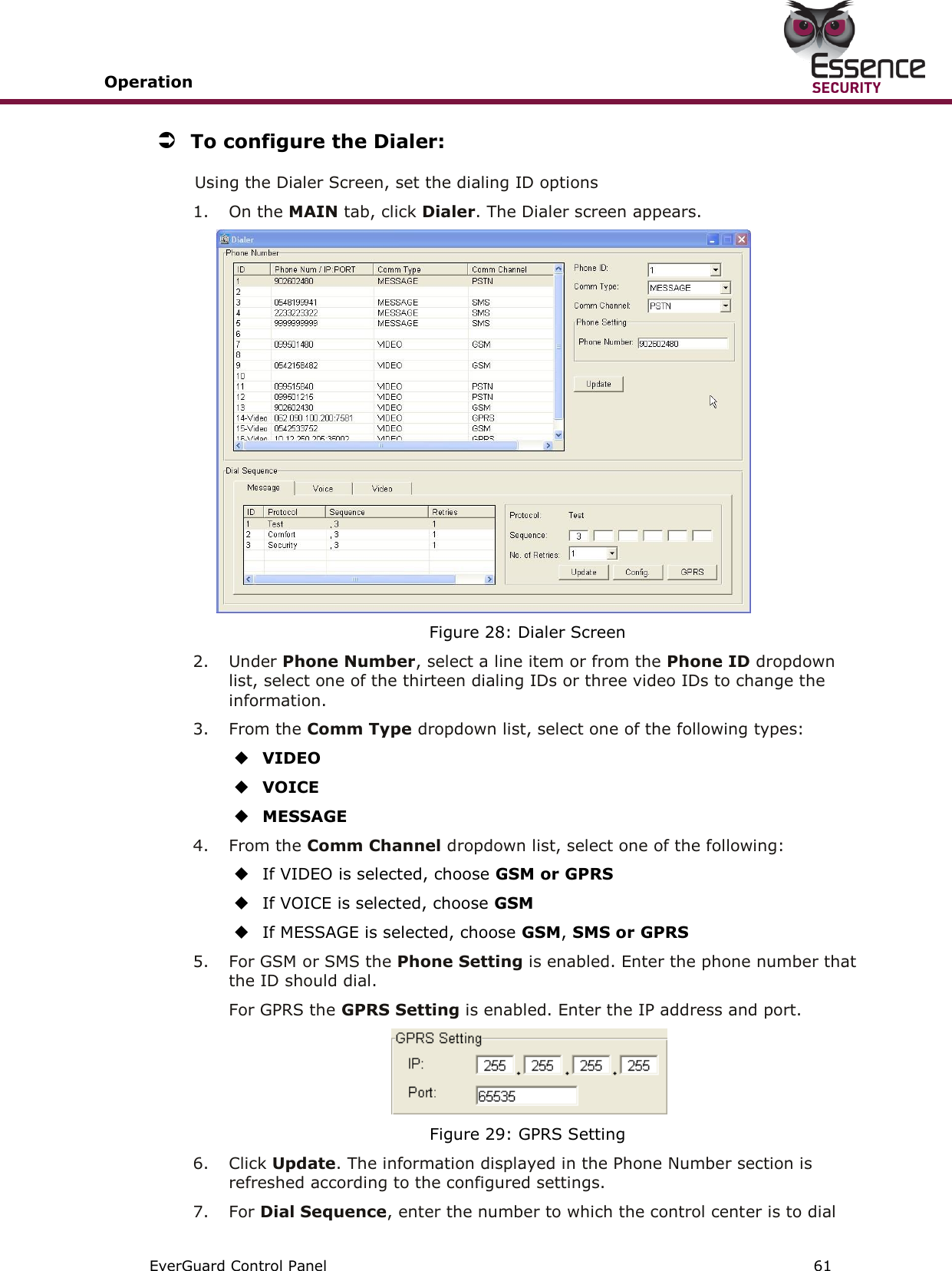
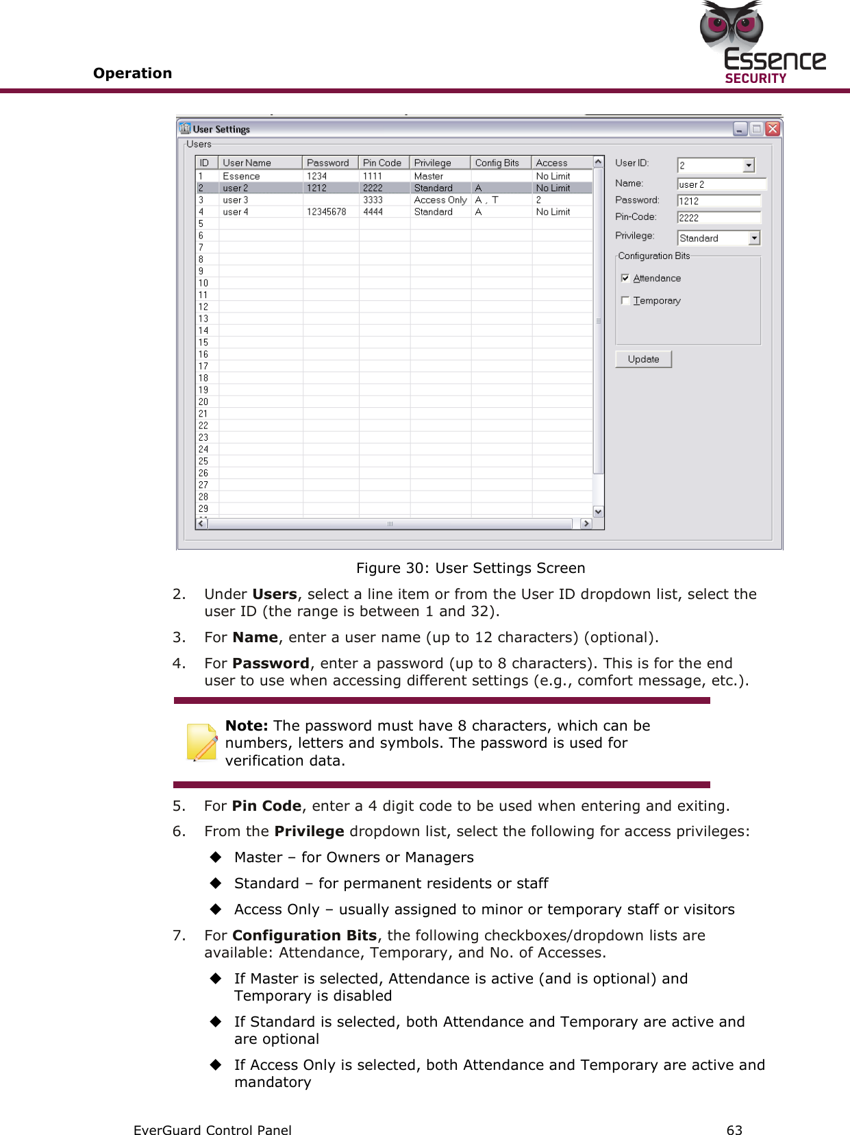
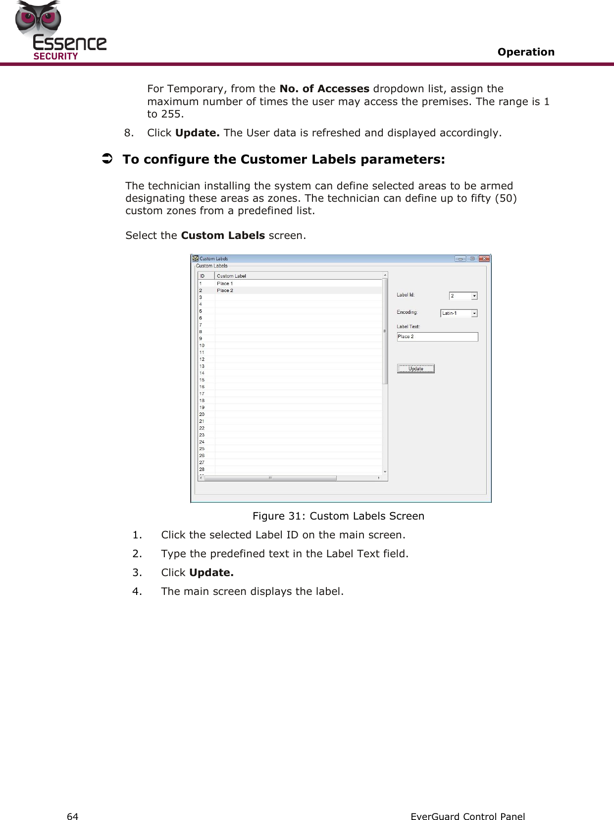
Essence Security ES7000EG Wireless Control Panel User Manual EverGuard Control Panel
Essence Security International ltd. Wireless Control Panel EverGuard Control Panel
UserManual.wiki
>
Essence Security
>
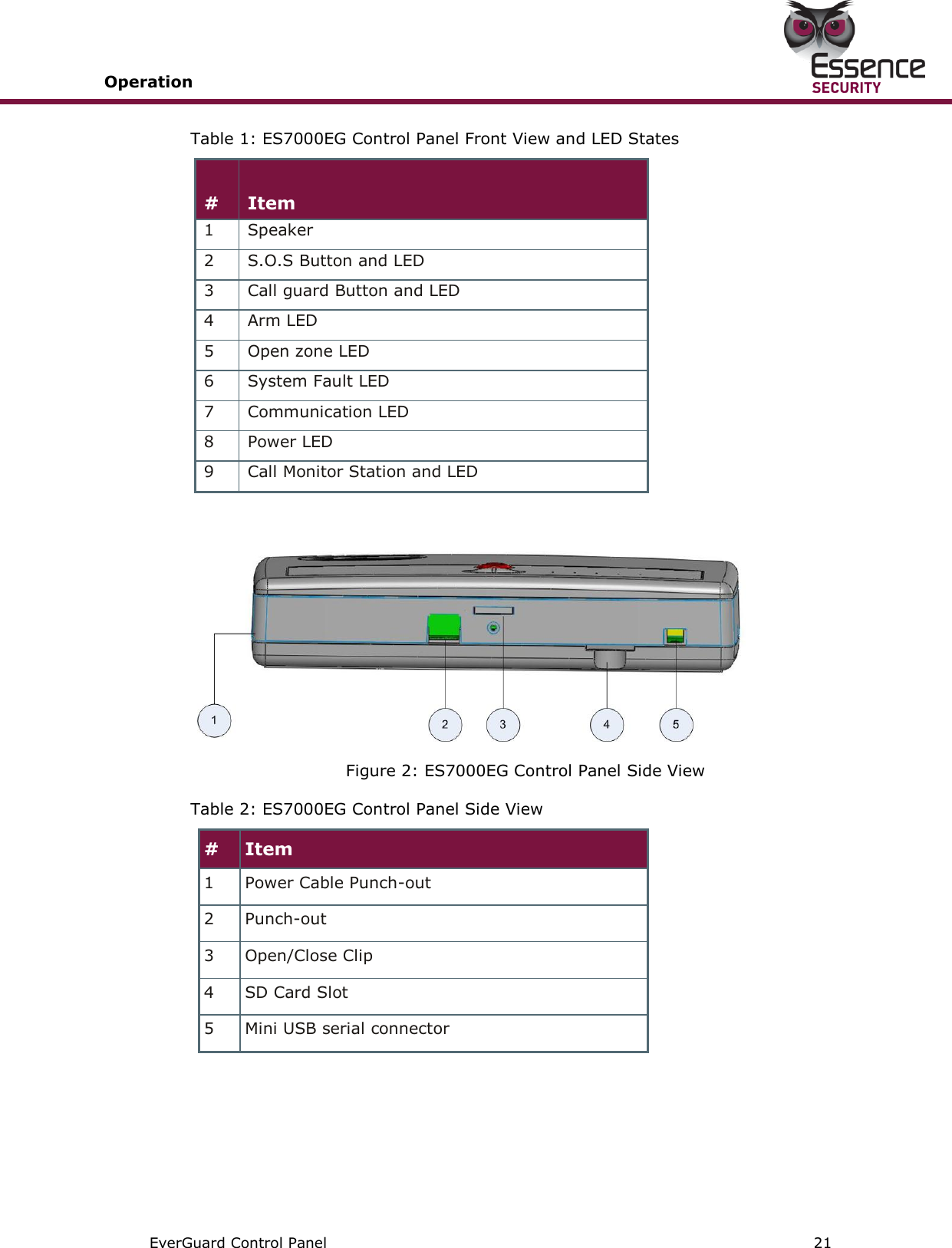
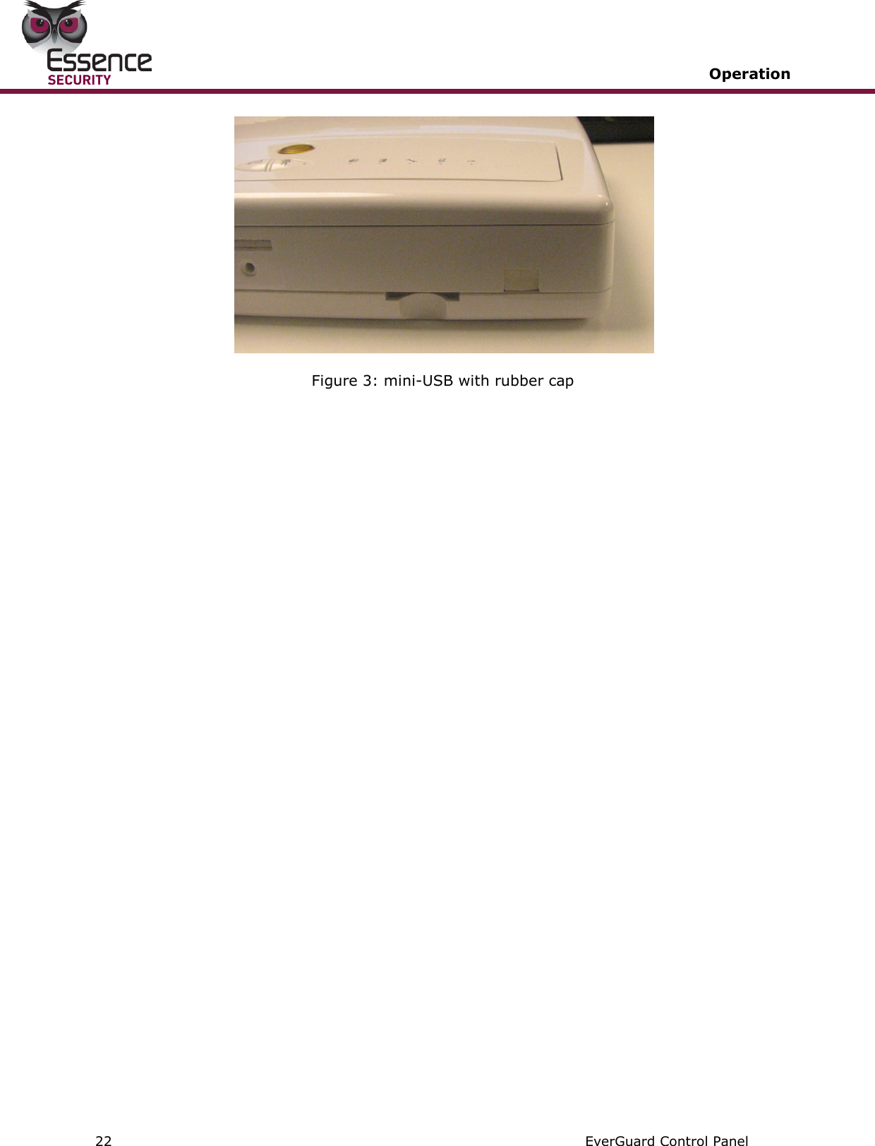
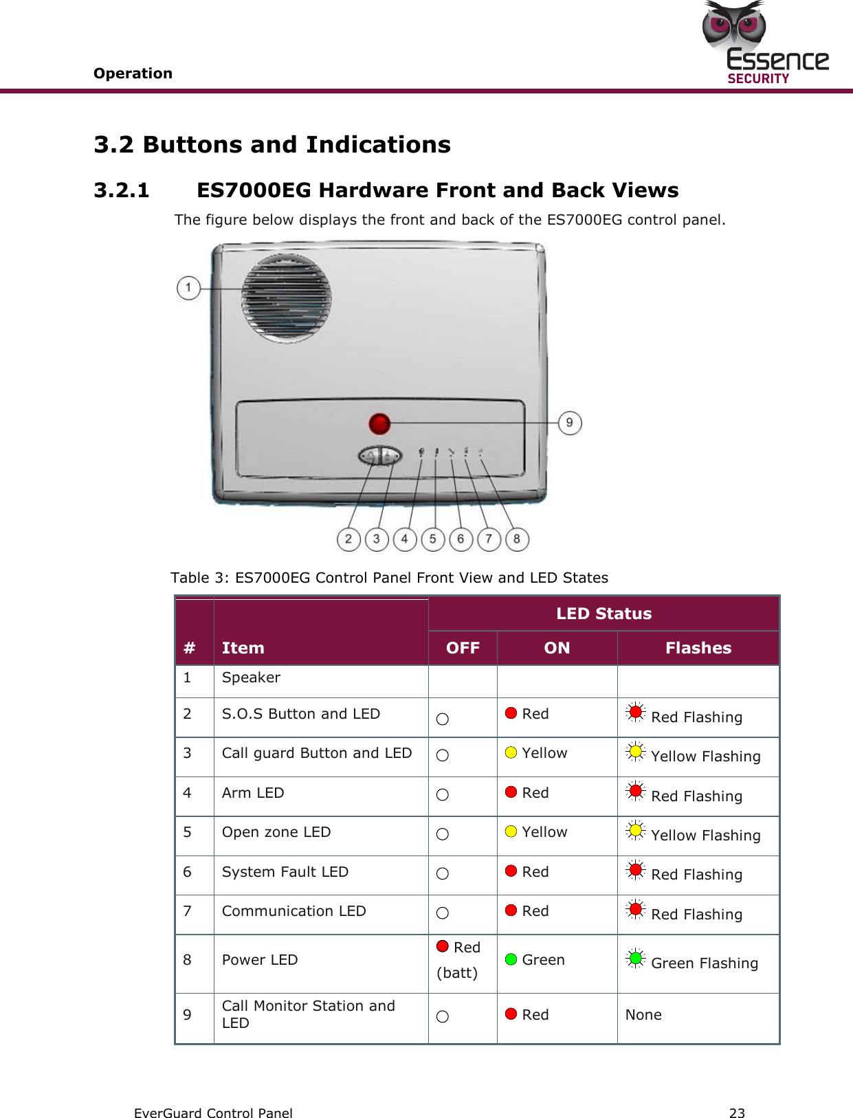
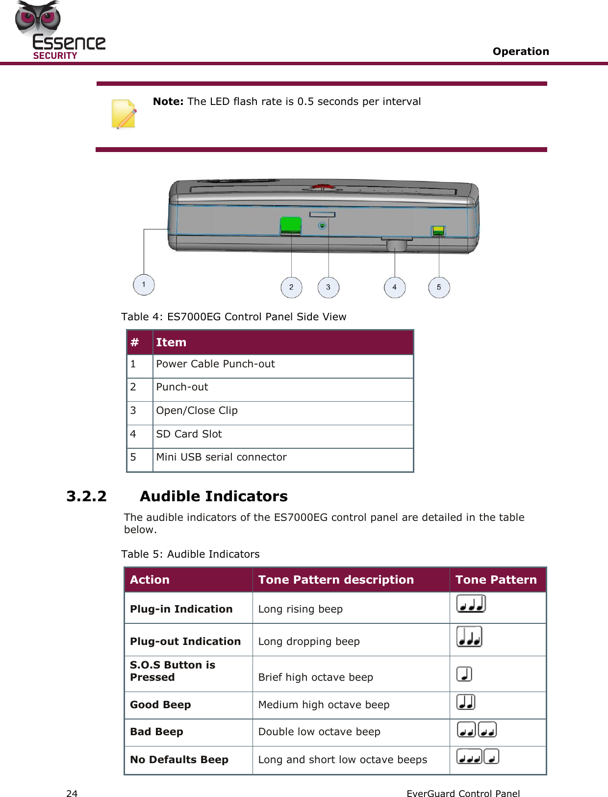
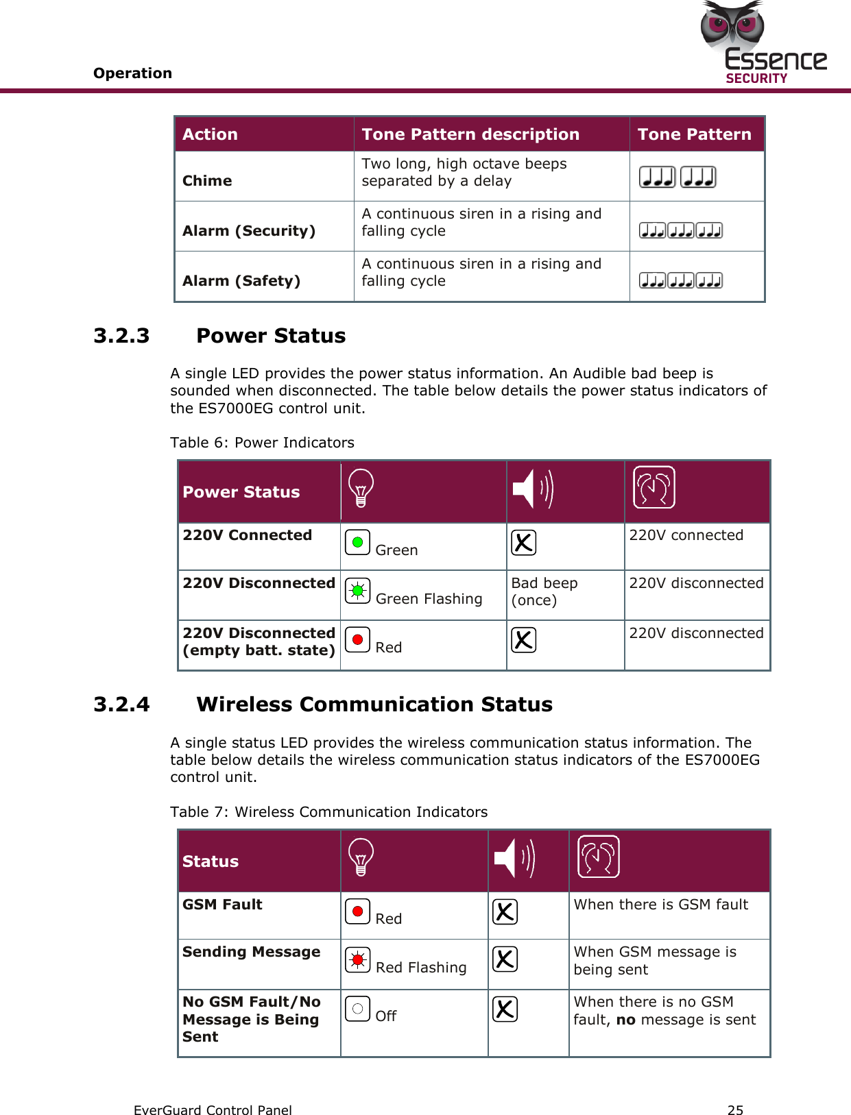
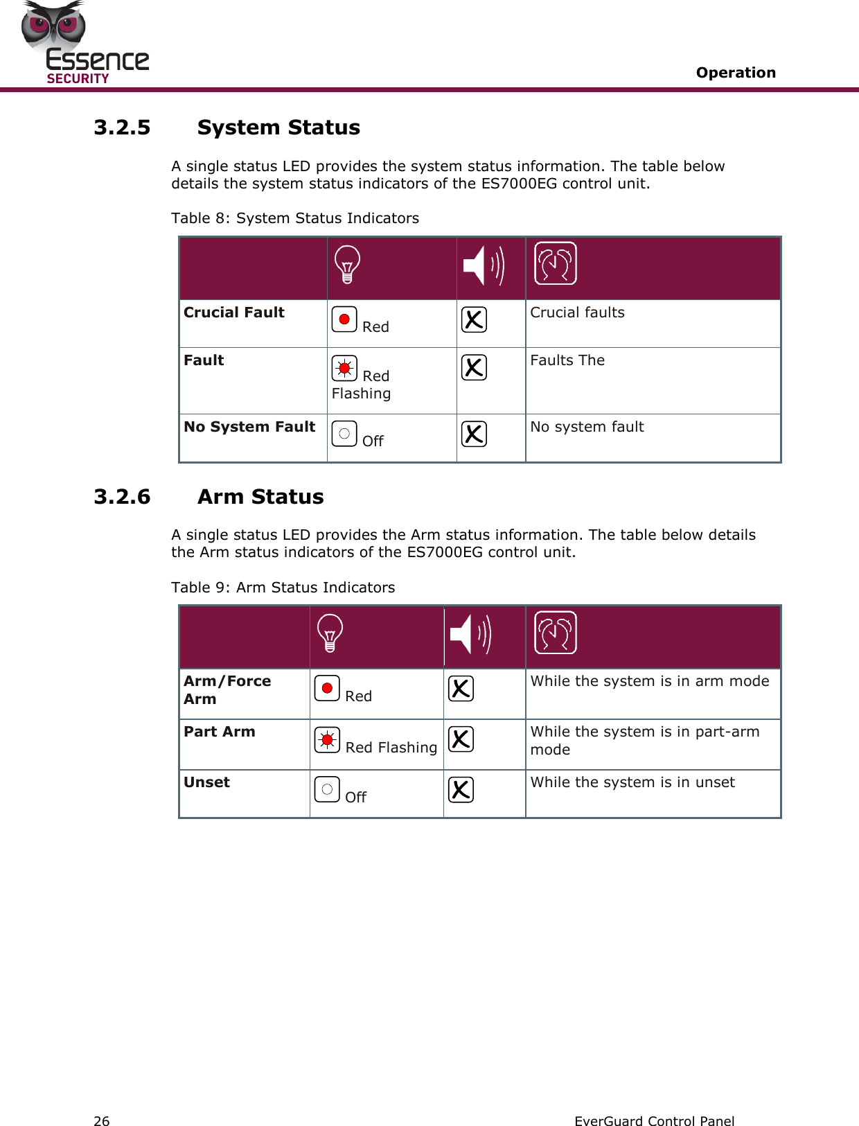
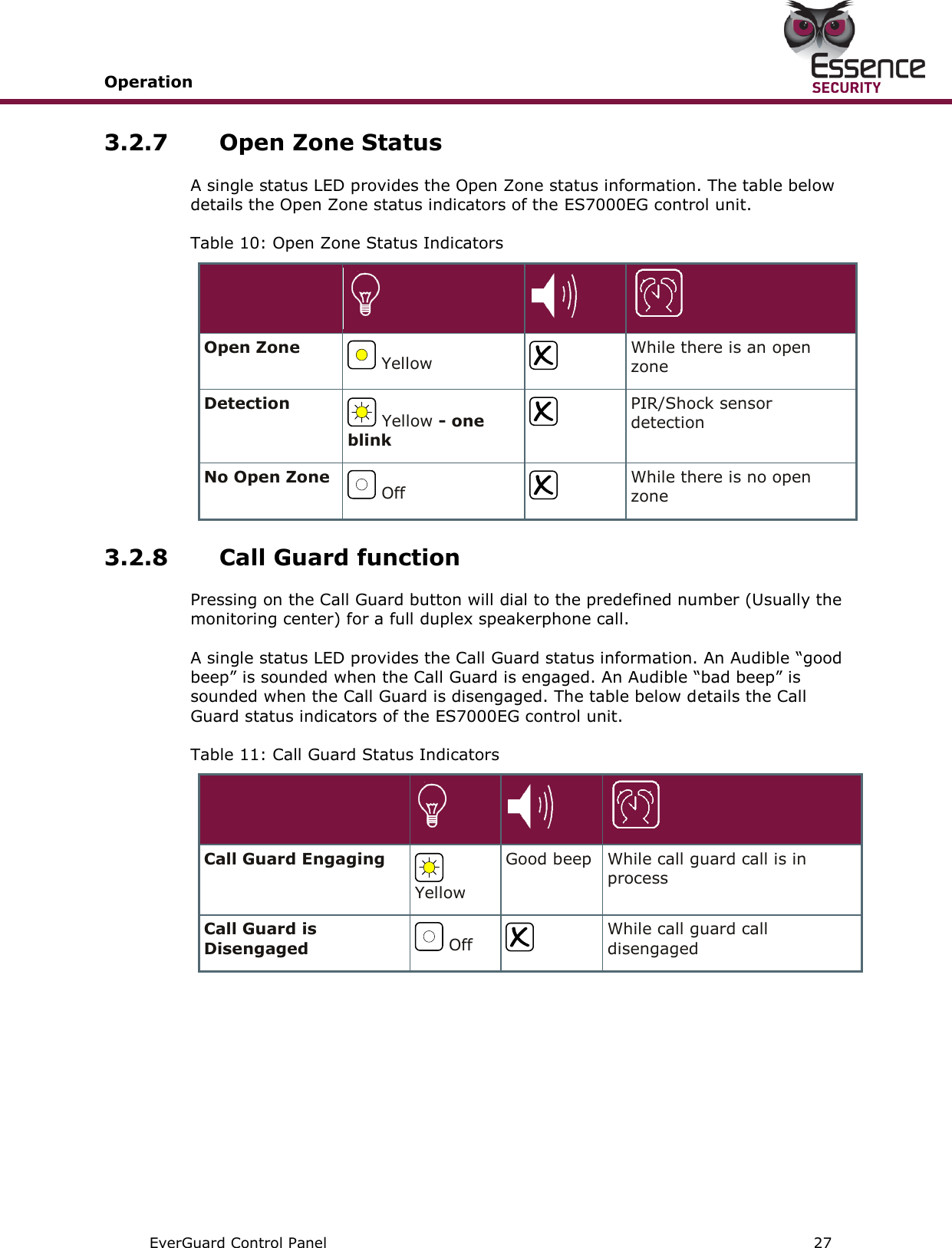
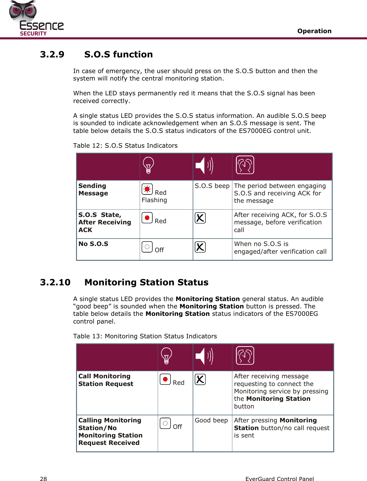
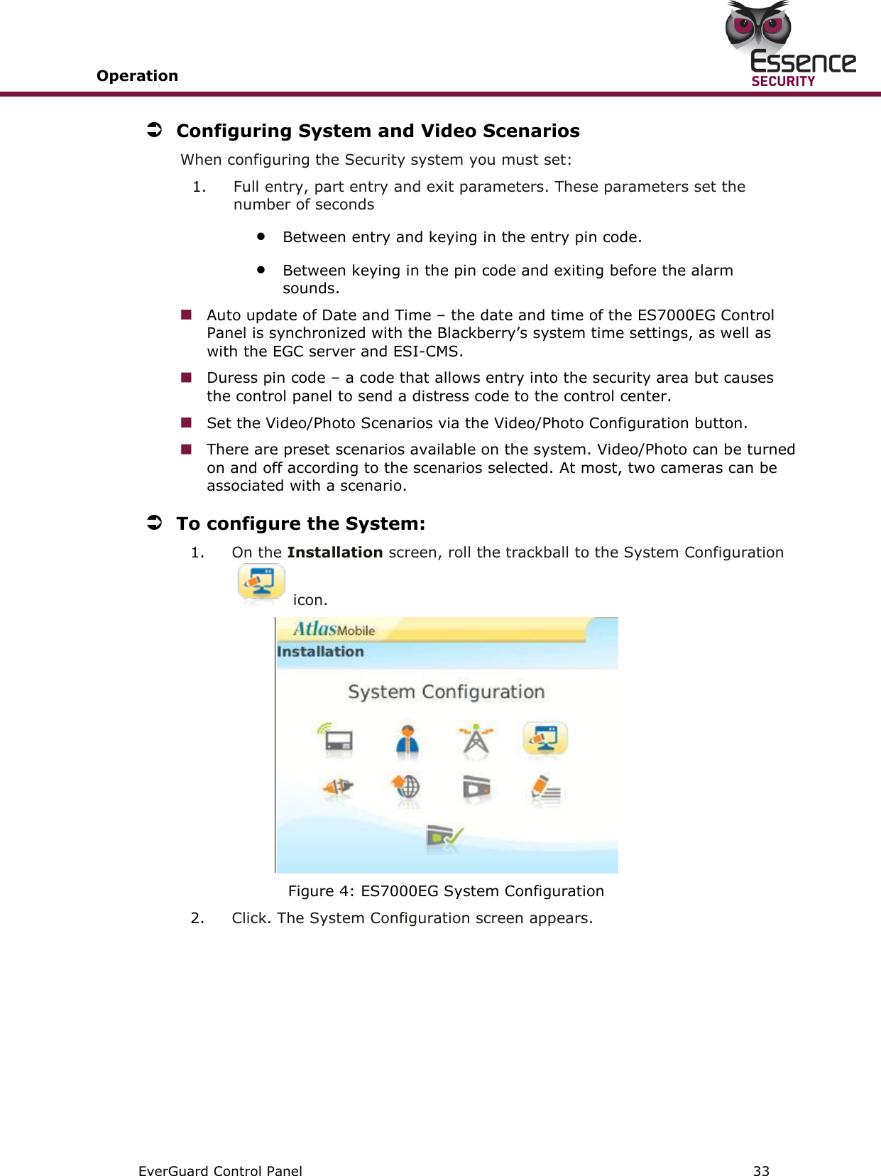
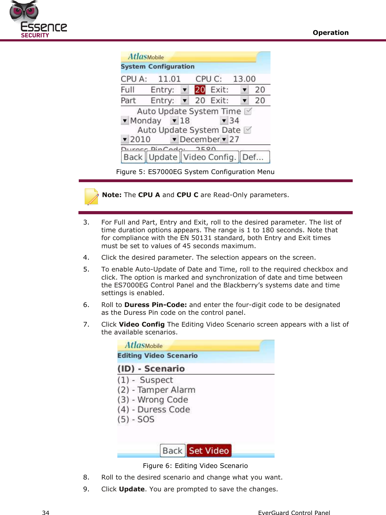
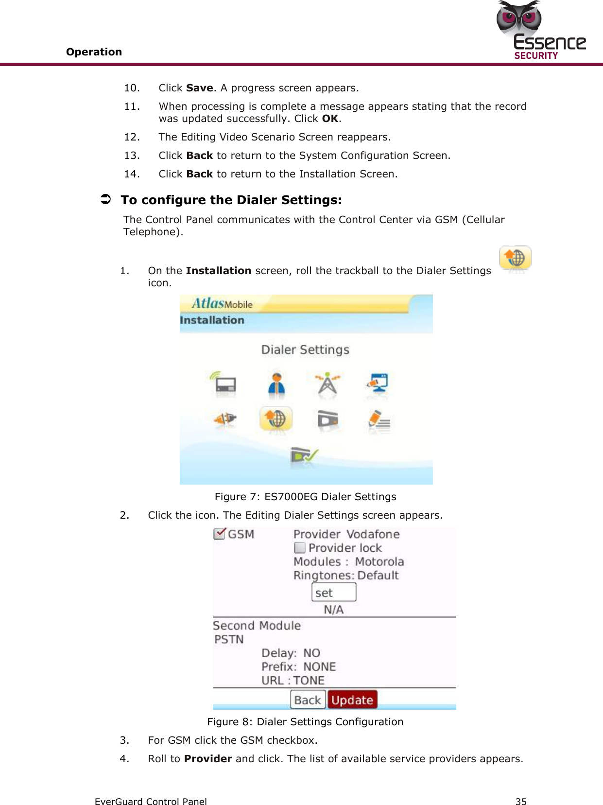
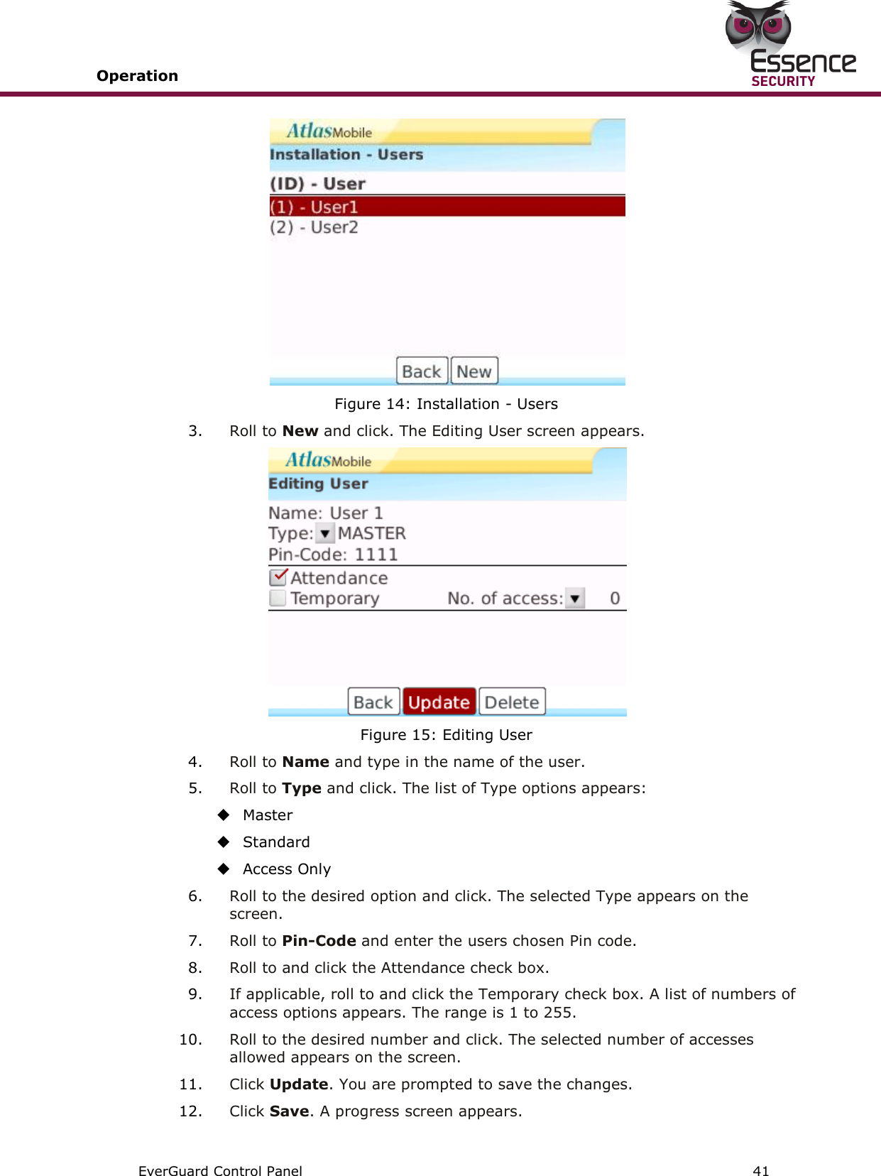
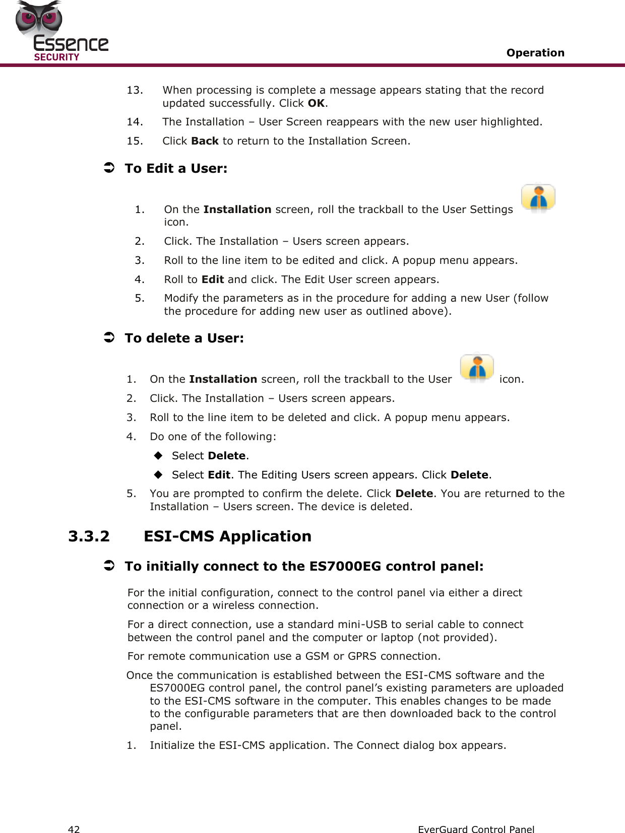
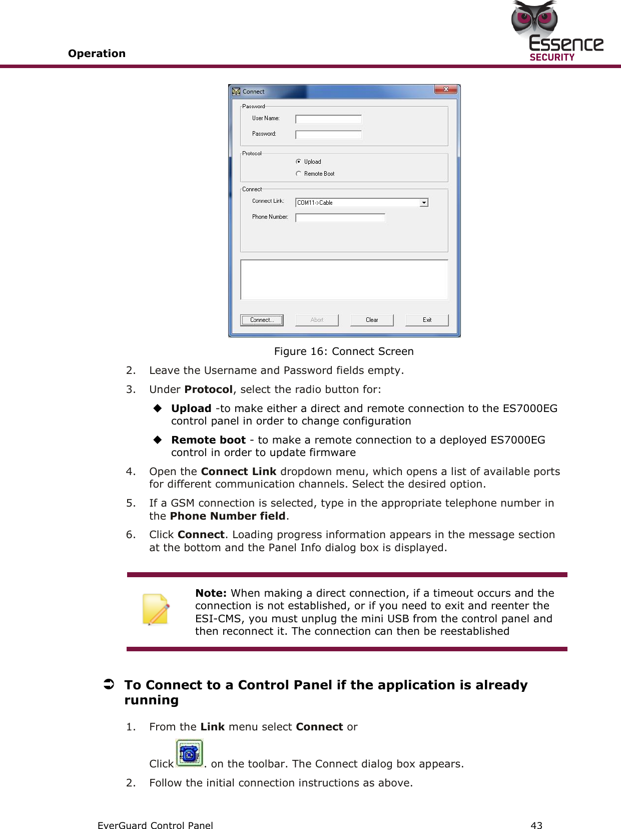
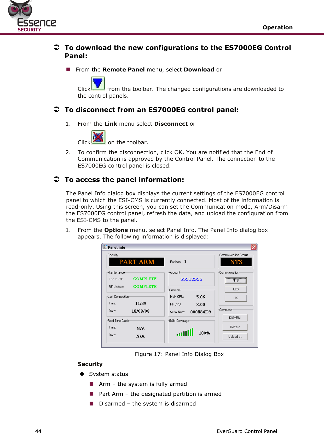
ES7000EG User Manual
manual
Navigation menu
Upload a User Manual
Namespaces
Wiki Guide
HTML
PDF
Info
Views
User Manual
Discussion / Help
Navigation