Essence Security ES7000EG Wireless Control Panel User Manual EverGuard Control Panel
Essence Security International ltd. Wireless Control Panel EverGuard Control Panel
manual

Part of the Essence Group
ES7000EG
Version 1.7_01
December 2011
EverGuard
Control Panel
User Guide

© 2011 Essence Security International Ltd.
All rights reserved.
This document is the protected intellectual property of the Essence Security
International Ltd. Any copying, reprinting, reuse, reproduction ,adaptation
distribution or translation without the prior written permission of Essence Security
Ltd is prohibited.
The information included in this document is subject to change without notice.
For more information, please contact:
Essence Security
12 Abba Eban Avenue, Ackerstein Towers Bldg. D
Herzliya Pituach
46120 Israel
www.essence-grp.com
Tel: +972-73-2447777
Fax: +972-9-7729962

Table of Contents
EverGuard Control Panel
3
Table of Contents
1 Overview ............................................................................................. 5
2 Installation .......................................................................................... 6
2.1 ES7000EG Wall Mount................................................................................. 6
2.2 GSM/GPRS Modem Installation ................................................................... 11
2.2.1 GSM/GPRS Modem Components ..................................................... 11
2.2.1.1 GSM/GPRS Modem .......................................................... 11
2.2.1.2 Antenna and Coaxial Cable............................................... 12
2.2.1.3 GSM/GPRS Modem Connector .......................................... 12
2.2.2 Mounting the GSM/GPRS Modem Antenna........................................ 15
2.3 Inserting the SIM Card .............................................................................. 17
2.4 Connecting the Mini USB Cable .................................................................. 18
3 Operation .......................................................................................... 20
3.1 About the ES7000EG Control Panel Equipment ............................................. 20
3.1.1 ES7000EG Hardware Front and Back Views ...................................... 20
3.2 Buttons and Indications ............................................................................. 23
3.2.1 ES7000EG Hardware Front and Back Views ...................................... 23
3.2.2 Audible Indicators ......................................................................... 24
3.2.3 Power Status ............................................................................... 25
3.2.4 Wireless Communication Status ...................................................... 25
3.2.5 System Status ............................................................................. 26
3.2.6 Arm Status .................................................................................. 26
3.2.7 Open Zone Status ......................................................................... 27
3.2.8 Call Guard function ....................................................................... 27
3.2.9 S.O.S function .............................................................................. 28
3.2.10 Monitoring Station Status .............................................................. 28
3.2.11 Detailed Operation and Modes ........................................................ 29
3.2.11.1 The Arm Cycle ................................................................ 29
3.2.12 Maintenance ................................................................................ 30
3.2.13 No Default ................................................................................... 30
3.2.14 Alarm 31
3.3 Optional Settings and Defaults ................................................................... 32
3.3.1 Atlas Mobile Application ................................................................. 32
3.3.2 ESI-CMS Application ..................................................................... 42

Table of Contents
4
EverGuard Control Panel
3.3.2.1 Toolbar .......................................................................... 46
3.3.2.2 Status Bar ..................................................................... 47
3.3.2.3 Navigation Pane ............................................................. 47
3.3.2.4 Main Tab ....................................................................... 47
3.3.2.5 CMD Tab ........................................................................ 48
3.3.2.6 Status Tab ..................................................................... 49
3.3.2.7 The control panel is divided into several parameter sets: ..... 50
4 Maintenance ...................................................................................... 66
5 FCC Radio frequency interference statement ..................................... 67
6 Specifications .................................................................................... 68
Overview
EverGuard Control Panel
5
1 Overview
The ES7000EG is a two-way, wireless control panel unit comprising the main
element of the EverGuard Control Panel security system. This unit receives Radio
Frequency (RF) signals from a full array of sensors and detectors, remote access
devices and interface devices, such as a key fob and key pad. It also transmits
bidirectional RF signals to these units providing supervision, re-configuration,
control and more.
The control panel has RF and GSM jamming detection and reporting feature,
making it very hard to be tampered or hacked.
This user guide provides detailed information on installing, configuring and
operation of the ES7000EG security system.
For information on the initial setup of the ES7000EG Security System, defining
the peripherals and setting the initial parameters, refer to the Atlas Mobile section
3.3.1 below.
For information on modifying and updating the ES7000EG Control Panel
parameters, refer to the ESI-CMS section 3.3.2 below2.

Installation
6
EverGuard Control Panel
2 Installation
2.1 ES7000EG Wall Mount
The ES7000EG can be mounted on a wall using the wall mount provided. In
addition, you must verify that there is adequate reception from the key pad
(ES700KPD) to the ES7000EG control panel and vice versa.
Note: The distance between the ES7000EG control panel and the
peripheral devices can be a maximum of 700 meters (2296 feet) (Open Air
Nominal) if there are no obstacles. The range can be augmented using the
ES700SOIR Repeater. (For more information on the ES700SIOR, refer to
the ES700SIOR User Guide.)
Mounting the ES700KPD requires the following components:
Drill with appropriate bit
Four (4) DIN 7982 cross recessed countersunk head tapping screws (4.2 x 40
mm) (not provided)
Standard appropriate screwdriver
To select a mounting location:
1. Find a suitable wall location:
Select a suitable location that is not too obvious, a secret or hidden
location that is not close to entry points, such as doors and windows.
The control panel must be located in an area that has good GSM signal
reception.
The control panel must be installed with a minimal distance of 20 cm
(0.66 ft) from users and nearby persons and must not be co-located or
operating in conjunction with any other antenna or transmitter.
The minimal installation height from the floor must be 70 cm (2.3 ft), and
at least 50 cm (1.65 ft) below the ceiling.
The control panel should be installed in a centric location, which means
centered between all the rooms and all the floors in the building.
The control panel should not be installed near:
High current electric appliances such refrigerators, washing
machines, electric or fuse boxes, etc.
Appliances such as cordless phones, TVs, which could cause
interference.
Heat sources such as stoves, radiators, or fireplaces, etc.
In any kind of metal enclosures like a metal cabinets or lockers.
2. Only after all the RF devices have been installed and tested, should the
installer mount the panel.
Installation
EverGuard Control Panel
7
In order to use the DVK RF test tool, the control panel location should be
selected first. The installer can then use the DVK tool to select the
location for all other devices.
To mount the ES7000EG control panel:
1. Identify a suitable location for the ES7000EG control panel according to the
guidelines above.
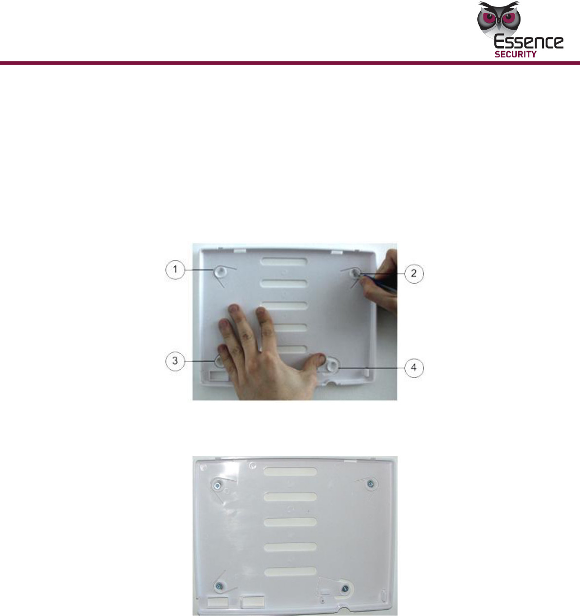
2. Remove the wall mount component from the ES7000EG control panel.
3. Place and hold the wall mount component on the desired mounting location.
Mark the desired drilling locations, using the four holes as shown below.
4. Using a drill with the appropriate drill bit, drill at the marked drilling locations.
5. Using the appropriate screwdriver, insert the four screws into the appropriate
locations on the wall mount component and secure them.
6. To open the ES7000EG control panel, use a large coin. Insert the coin into the
depression on the lower side of the panel. Twist the coin and the cover
separates from the main body.
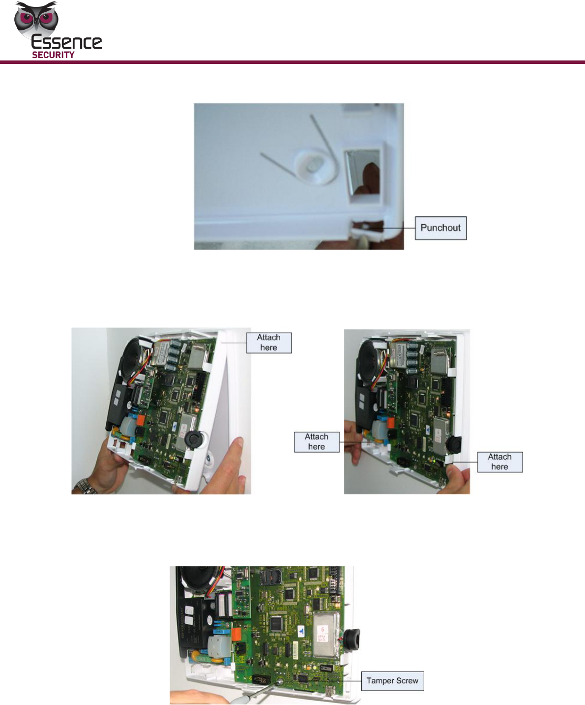
7. On the ES7000EG control panel main body, create an opening for the power
cable by removing the punch-out according to the figure below.
Installation
8
EverGuard Control Panel
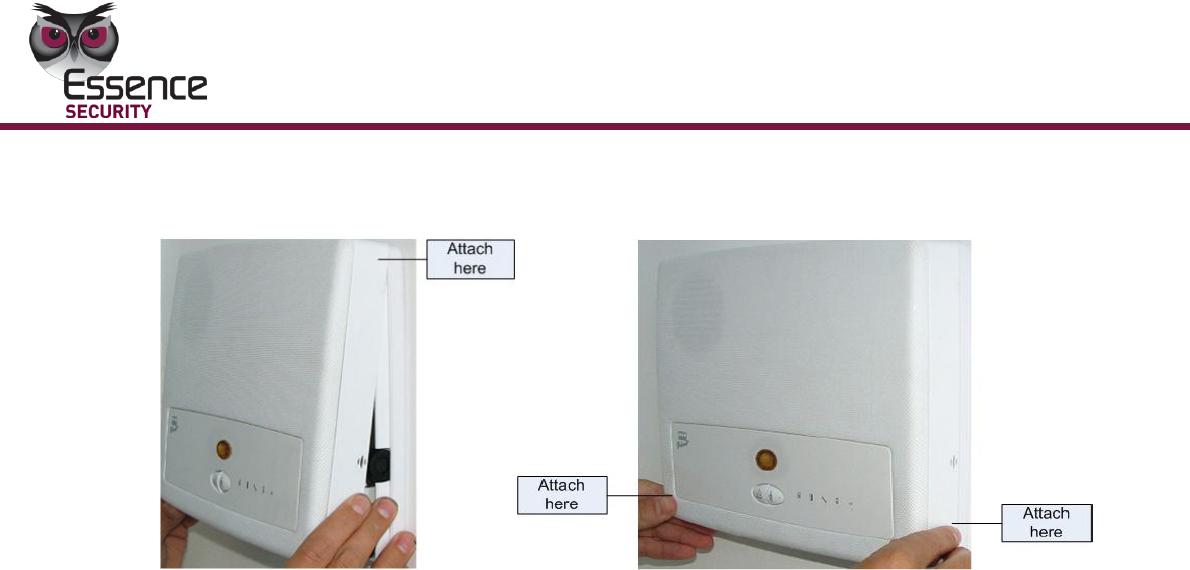
8. Attach the ES7000EG control panel to the wall mount, top first, then bottom
as shown in the figures below. ES7000EG control panel snaps into the
provided clips.
9. Using the appropriate screwdriver, insert the tamper screw and secure it in
place as shown in the figure below.
Installation
EverGuard Control Panel
9
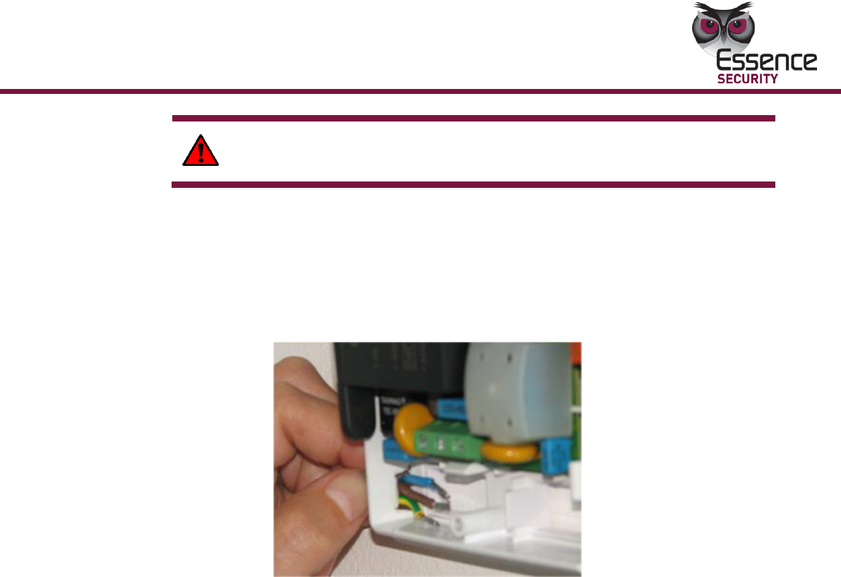
WARNING! 220V Hazard! Make sure AC cable is disconnected before
applying the following sections
10. Measure distance end-to-end of power cable from the ES7000EG control
panel to the power source to ascertain that it is of sufficient length.
11. Insert the power cable through the punch-out opening and secure the wires
to the terminal block connectors as shown in the figure below.
Connect the ground wire to the middle terminal block connector.
Connect the Live and neutral wires to the first and third terminal block
connectors.
12. If the system configuration requires wireless communication, attach the
GSM/GPRS modem and antenna according to the
Installation
10
EverGuard Control Panel
GSM/GPRS Modem Installation instructions in section 2.2 below
13. Attach the top cover, top first, then, bottom as shown in the figure below.
14. Connect the other end of the power cable to a plug.
15. Insert the plug into the designated power socket. The wall mount and
installation are complete.
Installation
EverGuard Control Panel
11
2.2 GSM/GPRS Modem Installation
The GSM/GPRS modem and antenna must be installed inside the ES7000EG
control panel for wireless communication. The mounting screws are supplied with
the modem kit.
Note: Be sure to follow the installation instructions closely so that the
antenna does not get disconnected.
2.2.1 GSM/GPRS Modem Components
The GSM/GPRS Modem components are comprised of:
GSM/GPRS modem
Antenna
Coaxial cable
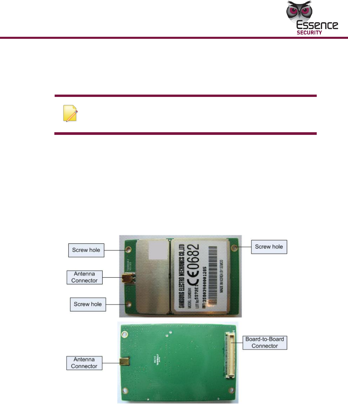
2.2.1.1 GSM/GPRS Modem
The figures below display the top and bottom view of the GSM/GPRS Modem.
The GSM/GPRS modem is comprised of:
Three screw holes
Installation
12
EverGuard Control Panel
Antenna Connector
Board-to-Board Connector (back view only)
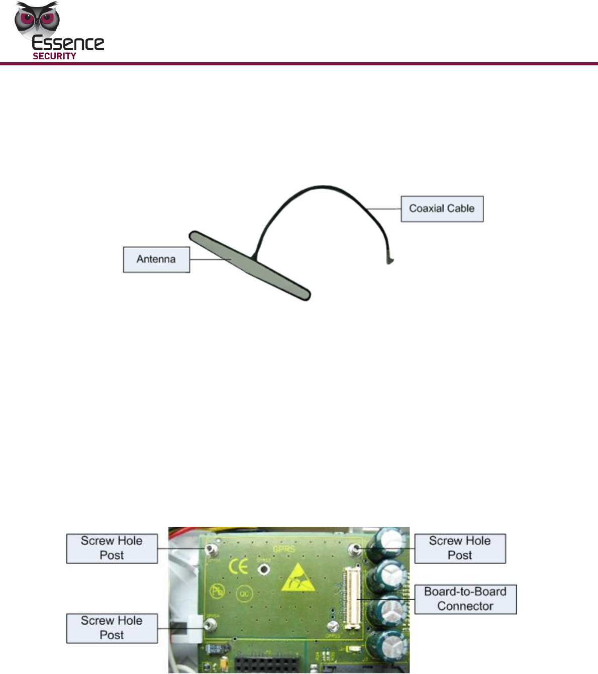
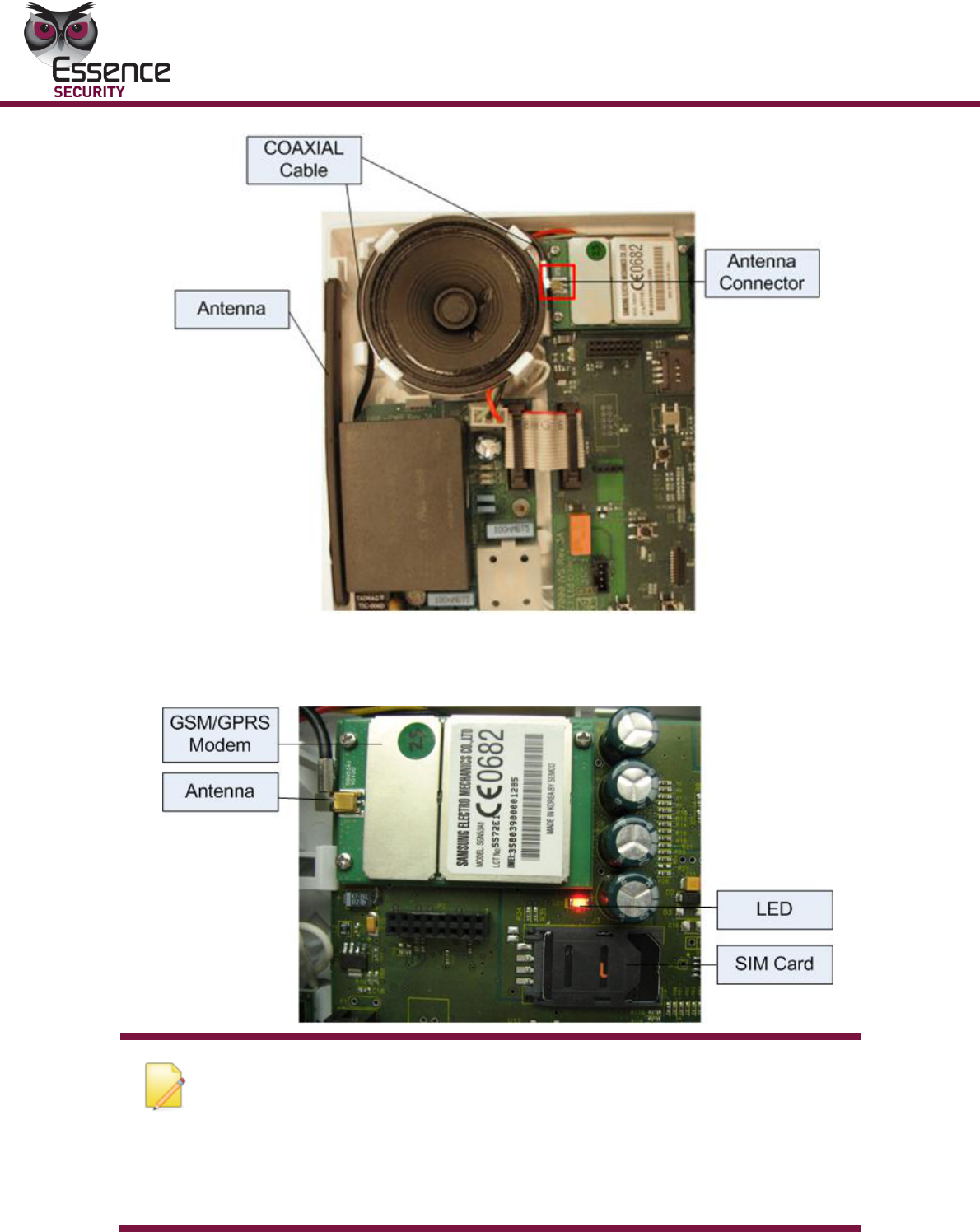
2.2.1.2 Antenna and Coaxial Cable
The figure below displays the Antenna and Coaxial Cable.
The GSM/GPRS Antenna is comprised of:
Antenna
COAXIAL Cable
Antenna Connector (at the end of the COAXIAL Cable)
2.2.1.3 GSM/GPRS Modem Connector
The GSM/GPRS Modem Connector is inside the ES7000EG control panel, on the
upper left corner of the printed circuit board. It connects to the bottom of the
GSM/GPRS Modem and contains:
Three screw hole posts
Board-to-Board Connector
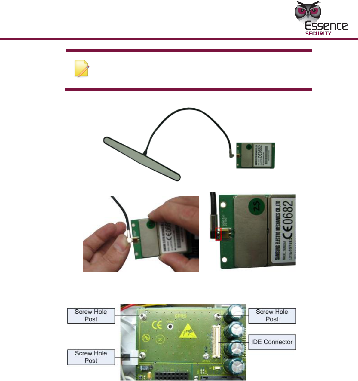
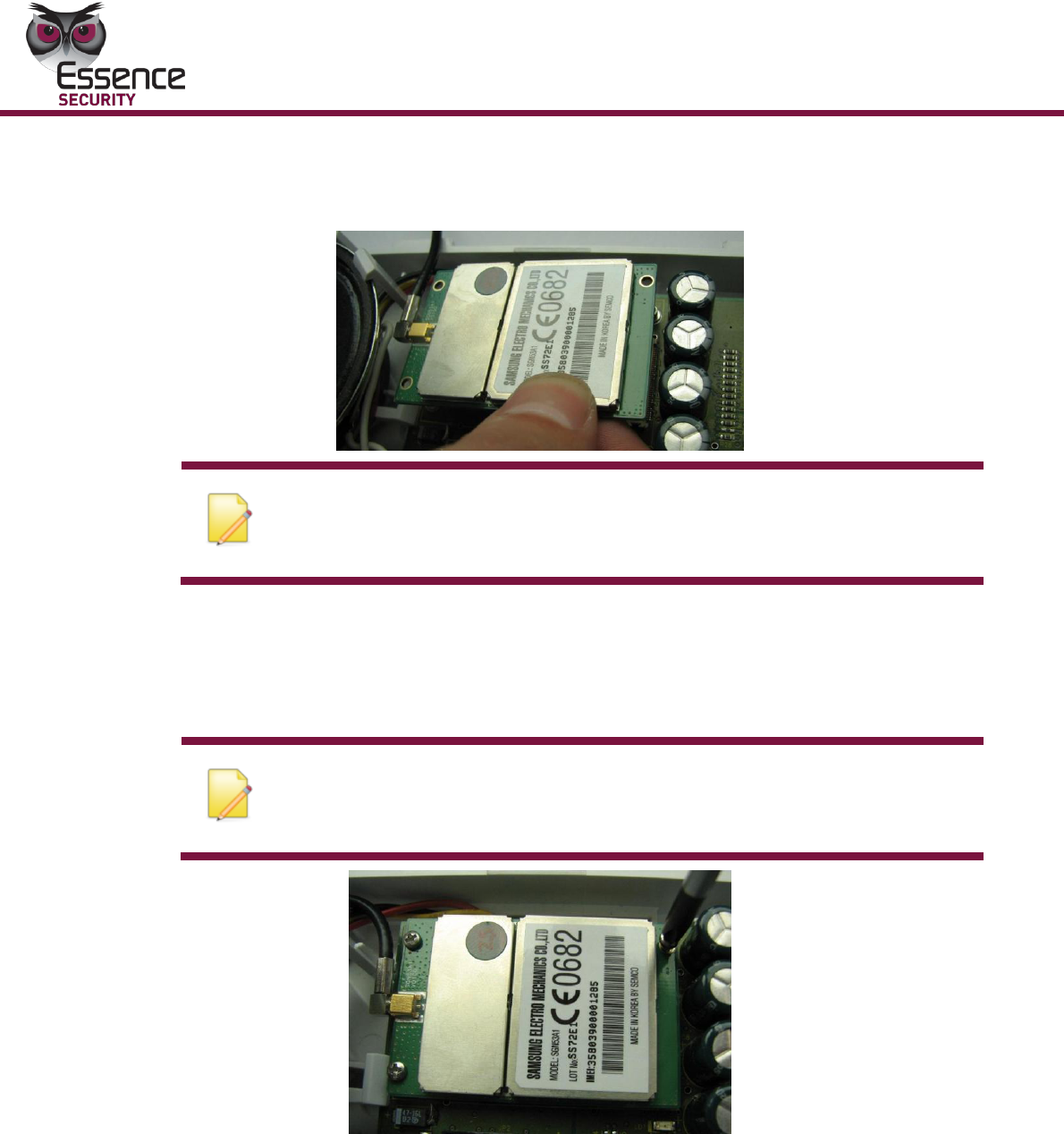
To install the GSM/GPRS modem:
1. Connect the coax cable connector of the antenna to the antenna
connector of the GSM/GPRS modem.
Installation
EverGuard Control Panel
13
Note: The pictures of the GSM/GPRS module below are an
example only. The actual brand and part-number of the module
may vary.
2. Verify that the connection is stable and firm.
3. With the ES7000EG control panel open, locate the GSM/GPRS Modem
Connector at the corner of the panel’s circuit board. It is labeled GPRS.
Installation
14
EverGuard Control Panel
4. Place the GSM/GPRS modem so that the screw holes line up with the
screw holes protrusions.
Note: Be careful not to not to disconnect the antenna while performing
this function. Antenna disconnection causes a fault in the system when
trying to connect to the GSM network.
5. Push down so that the Board-to-Board IDE Connectors match up and
connect.
6. Using the appropriate screwdriver, attach the three screws so that the
Modem Connector is securely fastened to the modem board.
Note: Use the screws supplied with the modem kit. Unspecified screws can
damage the GSM/GPRS Modem Hardware as well as its functionality.
Installation
EverGuard Control Panel
15
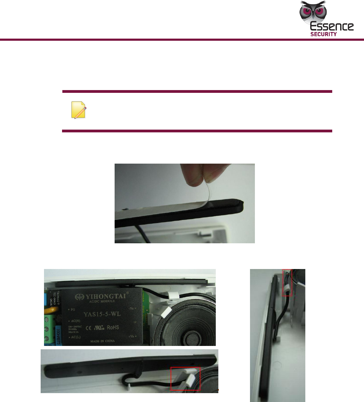
2.2.2 Mounting the GSM/GPRS Modem Antenna
The GSM/GPRS modem antenna is mounted on the upper side of the ES7000EG
control panel’s inner casing.
Note: Be sure to follow the installation instructions closely so that the
coaxial cable is positioned correctly and the antenna does not get
disconnected.
To mount the GSM/GPRS modem antenna:
1. Remove the protective plastic on the antenna to reveal double-sided tape.
2. Thread the coaxial cable and place the antenna on the inner casing at the top
of the ES7000 shell as shown in the figure below.
3. Double check to make sure that the modem and antenna have been mounted
in the correct positions (as is shown in the figures below).
Installation
16
EverGuard Control Panel
4. Insert the SIM Card according to the instructions in section 2.3 “ Inserting the
SIM Card”.
The figure below displays the full GSM/GPRS hardware assembly.
Note: When using a Samsung brand module with the ES7000EG control
panel connected to a power source, The LED lights up to indicate that the
GSM/GPRS Modem is synchronized with the GSM network. From power-up,
synchronization between the modem and the wireless telephone system
may take approximately two minutes.
When using Motorola brand module, this LED indicates an active GPRS
session.
Installation
EverGuard Control Panel
17
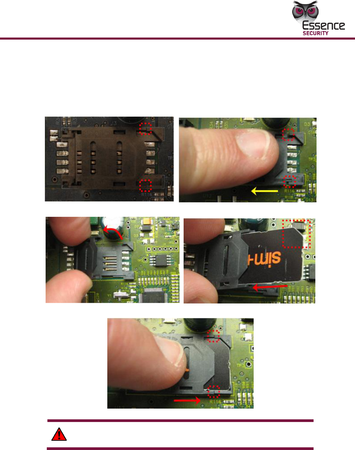
2.3 Inserting the SIM Card
As part of the GSM/GPRS transmission configuration, a SIM card is inserted into a
holder on the ES7000EG control panel’s circuit board.
To insert the SIM card:
5. Gently press down with your finger to slide the cover and pull the flap in the
direction as shown below.
6. Open the SIM card holder cover and insert the SIM card.
7. Close the SIM card holder cover and slide it back into place as shown below.
WARNING! Trying to insert a SIM card in the wrong direction can damage the
SIM card. Be sure to follow the above figures to assure the correct alignment.
Installation
18
EverGuard Control Panel
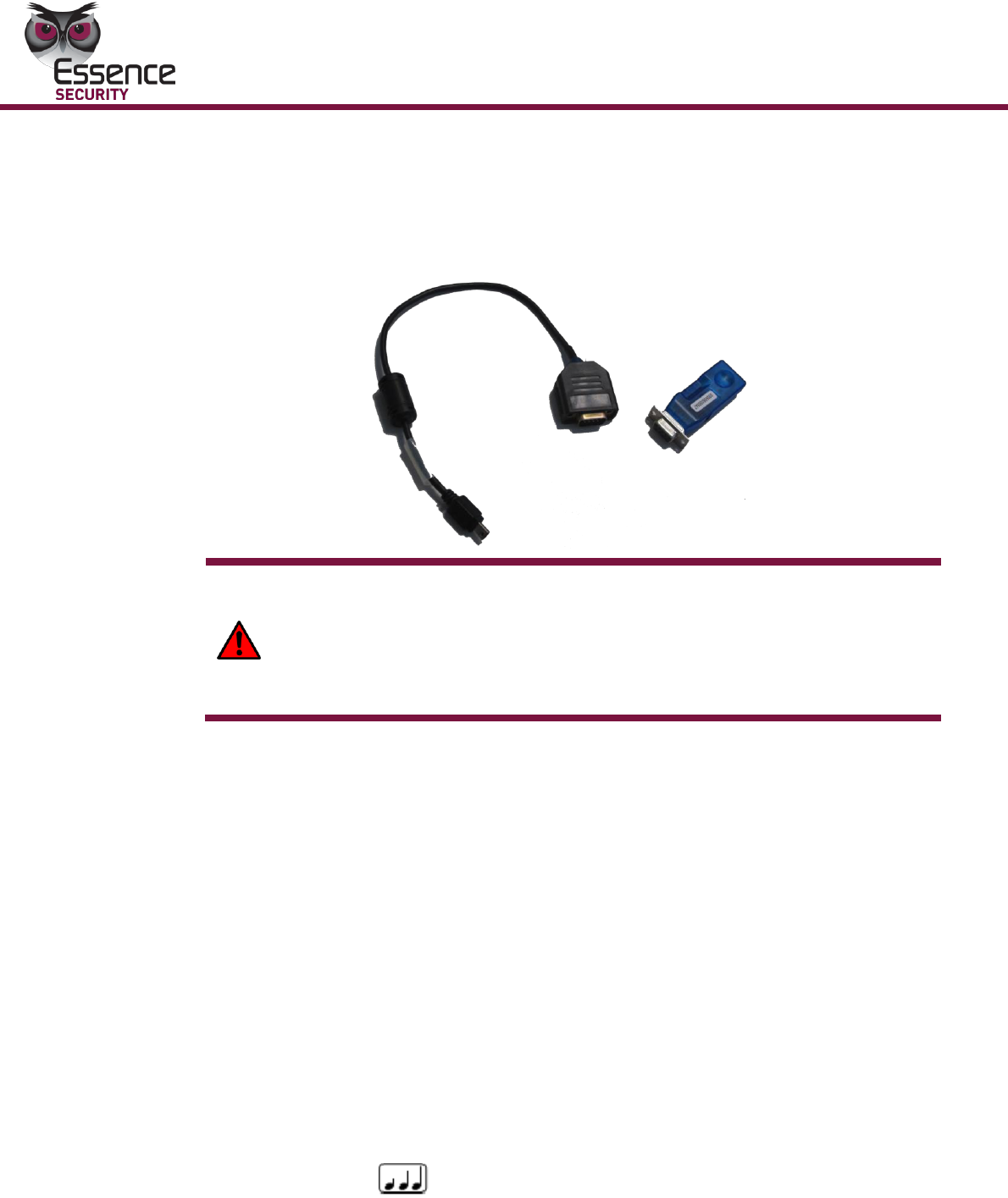
2.4 Connecting the Mini USB Cable
For initial setup using the Atlas Mobile application with the BlackBerry
Smartphone, each professional installer is provided with a Wireless Bluetooth
dongle and a specially designed Mini-USB cable that can be attached to the
ES7000EG control panel for setup.
WARNING! The mini USB port on the ES7000EG is not a real USB. It is
uniquely designed for use with the specific cable used by installers. Do not
connect to any USB equipment because it could seriously damage both the
ES7000EG and the USB equipment.
The end user must never use or access this Mini-USB port.
For information on the initial setup of the ES7000EG Security System using the
Atlas Mobile application via BlackBerry Smartphone, defining the peripherals and
setting the initial parameters, refer to the Atlas Mobile chapter 3.3.1 below.
For initial setup or for modifying the parameter configuration using the ESI-CMS
application, the professional installer is provided a special Mini-USB cable (with an
active electronic circuit) that enables the installer to connect a laptop or PC to the
ES7000EG control panel for setup.
For information on modifying and updating the ES7000EG Control Panel
parameters using the ESI-CMS application, refer to the ESI-CMS chapter 3.3.2
below.
To connect the Mini USB cable:
1. Locate the Mini USB connector on the bottom of the ES7000EG panel.
2. Insert the special Mini USB cable into the Mini USB connector. The
ES7000EG panel enters Installation mode and the 10 numbered LEDs on
the panel flash yellow.
3. If connection is approved and successful, the panel will sound the “long
rising tone” which symbolizes the “plug-in indication”.
4. If connection is not successful the panel will sound a bad beep.
5. After successful connection, when disconnecting the cable, the panel will
Special cable
Bluetooth dongle

EverGuard Control Panel
19
sound the “long dropping tone” which symbolizes the “plug-out
indication”.
Operation
20
EverGuard Control Panel
3 Operation
3.1 About the ES7000EG Control Panel Equipment
The ES7000EG Control Panel can utilize the following auxiliary equipment:
GSM/GPRS Modem – required for wireless communication
Antenna and Coaxial Cable – required for wireless communication
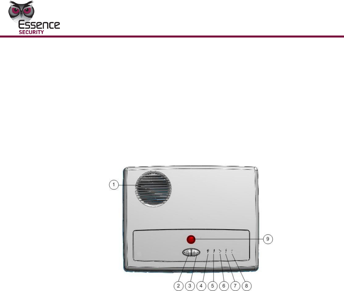
3.1.1 ES7000EG Hardware Front and Back Views
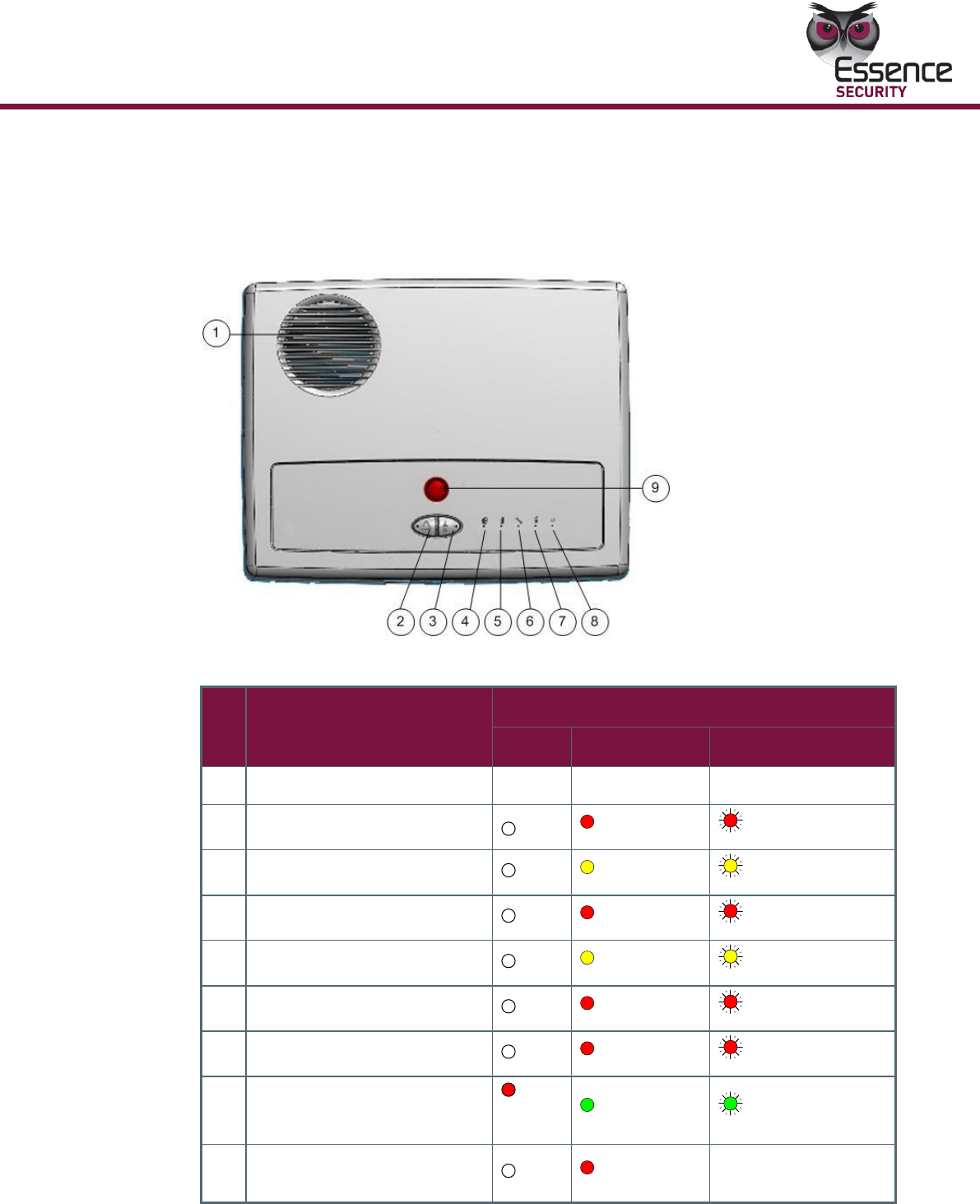
The figures below display the front and back of the ES7000EG control panel.
Figure 1: ES7000EG Control Panel Front View
Operation
EverGuard Control Panel
21
Table 1: ES7000EG Control Panel Front View and LED States
#
Item
1
Speaker
2
S.O.S Button and LED
3
Call guard Button and LED
4
Arm LED
5
Open zone LED
6
System Fault LED
7
Communication LED
8
Power LED
9
Call Monitor Station and LED
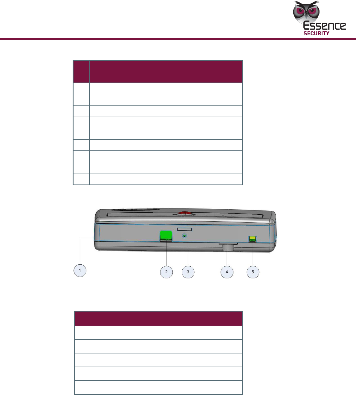
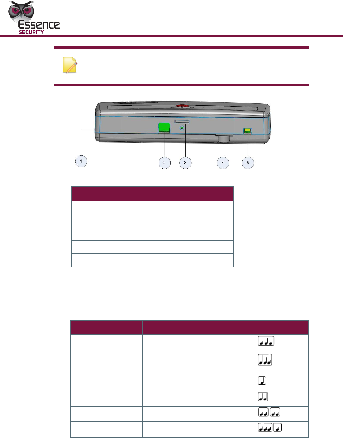
Figure 2: ES7000EG Control Panel Side View
Table 2: ES7000EG Control Panel Side View
#
Item
1
Power Cable Punch-out
2
Punch-out
3
Open/Close Clip
4
SD Card Slot
5
Mini USB serial connector
Operation
22
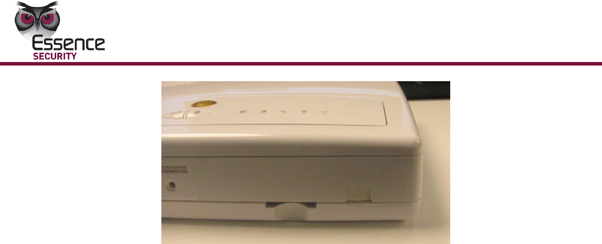
EverGuard Control Panel
Figure 3: mini-USB with rubber cap
Operation
EverGuard Control Panel
23
3.2 Buttons and Indications
3.2.1 ES7000EG Hardware Front and Back Views
The figure below displays the front and back of the ES7000EG control panel.
Table 3: ES7000EG Control Panel Front View and LED States
#
Item
LED Status
OFF
ON
Flashes
1
Speaker
2
S.O.S Button and LED
Red
Red Flashing
3
Call guard Button and LED
Yellow
Yellow Flashing
4
Arm LED
Red
Red Flashing
5
Open zone LED
Yellow
Yellow Flashing
6
System Fault LED
Red
Red Flashing
7
Communication LED
Red
Red Flashing
8
Power LED
Red
(batt)
Green
Green Flashing
9
Call Monitor Station and
LED
Red
None
Operation
24
EverGuard Control Panel
Note: The LED flash rate is 0.5 seconds per interval
Table 4: ES7000EG Control Panel Side View
#
Item
1
Power Cable Punch-out
2
Punch-out
3
Open/Close Clip
4
SD Card Slot
5
Mini USB serial connector
3.2.2 Audible Indicators
The audible indicators of the ES7000EG control panel are detailed in the table
below.
Table 5: Audible Indicators
Action
Tone Pattern description
Tone Pattern
Plug-in Indication
Long rising beep
Plug-out Indication
Long dropping beep
S.O.S Button is
Pressed
Brief high octave beep
Good Beep
Medium high octave beep
Bad Beep
Double low octave beep
No Defaults Beep
Long and short low octave beeps
Operation
EverGuard Control Panel
25
Action
Tone Pattern description
Tone Pattern
Chime
Two long, high octave beeps
separated by a delay
Alarm (Security)
A continuous siren in a rising and
falling cycle
Alarm (Safety)
A continuous siren in a rising and
falling cycle
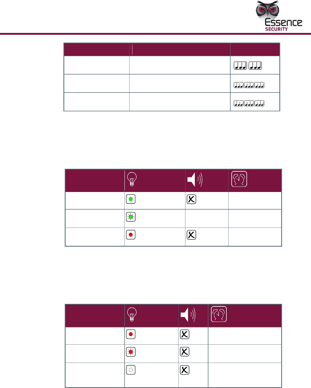
3.2.3 Power Status
A single LED provides the power status information. An Audible bad beep is
sounded when disconnected. The table below details the power status indicators of
the ES7000EG control unit.
Table 6: Power Indicators
Power Status
220V Connected
Green
220V connected
220V Disconnected
Green Flashing
Bad beep
(once)
220V disconnected
220V Disconnected
(empty batt. state)
Red
220V disconnected
3.2.4 Wireless Communication Status
A single status LED provides the wireless communication status information. The
table below details the wireless communication status indicators of the ES7000EG
control unit.
Table 7: Wireless Communication Indicators
Status
GSM Fault
Red
When there is GSM fault
Sending Message
Red Flashing
When GSM message is
being sent
No GSM Fault/No
Message is Being
Sent
Off
When there is no GSM
fault, no message is sent
Operation
26
EverGuard Control Panel
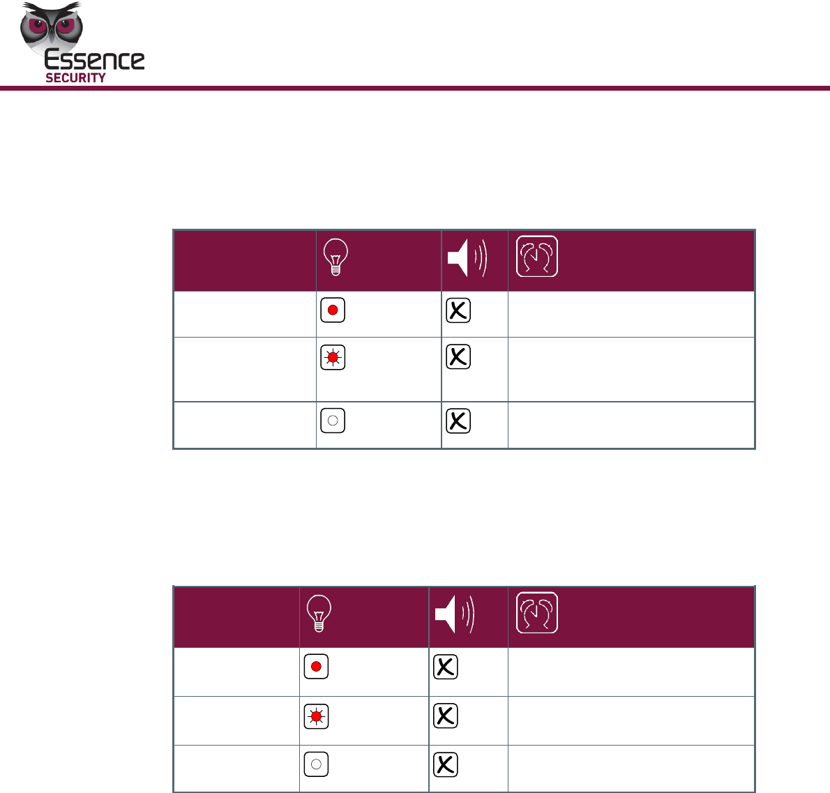
3.2.5 System Status
A single status LED provides the system status information. The table below
details the system status indicators of the ES7000EG control unit.
Table 8: System Status Indicators
Crucial Fault
Red
Crucial faults
Fault
Red
Flashing
Faults The
No System Fault
Off
No system fault
3.2.6 Arm Status
A single status LED provides the Arm status information. The table below details
the Arm status indicators of the ES7000EG control unit.
Table 9: Arm Status Indicators
Arm/Force
Arm
Red
While the system is in arm mode
Part Arm
Red Flashing
While the system is in part-arm
mode
Unset
Off
While the system is in unset
Operation
EverGuard Control Panel
27
3.2.7 Open Zone Status
A single status LED provides the Open Zone status information. The table below
details the Open Zone status indicators of the ES7000EG control unit.
Table 10: Open Zone Status Indicators
Open Zone
Yellow
While there is an open
zone
Detection
Yellow - one
blink
PIR/Shock sensor
detection
No Open Zone
Off
While there is no open
zone
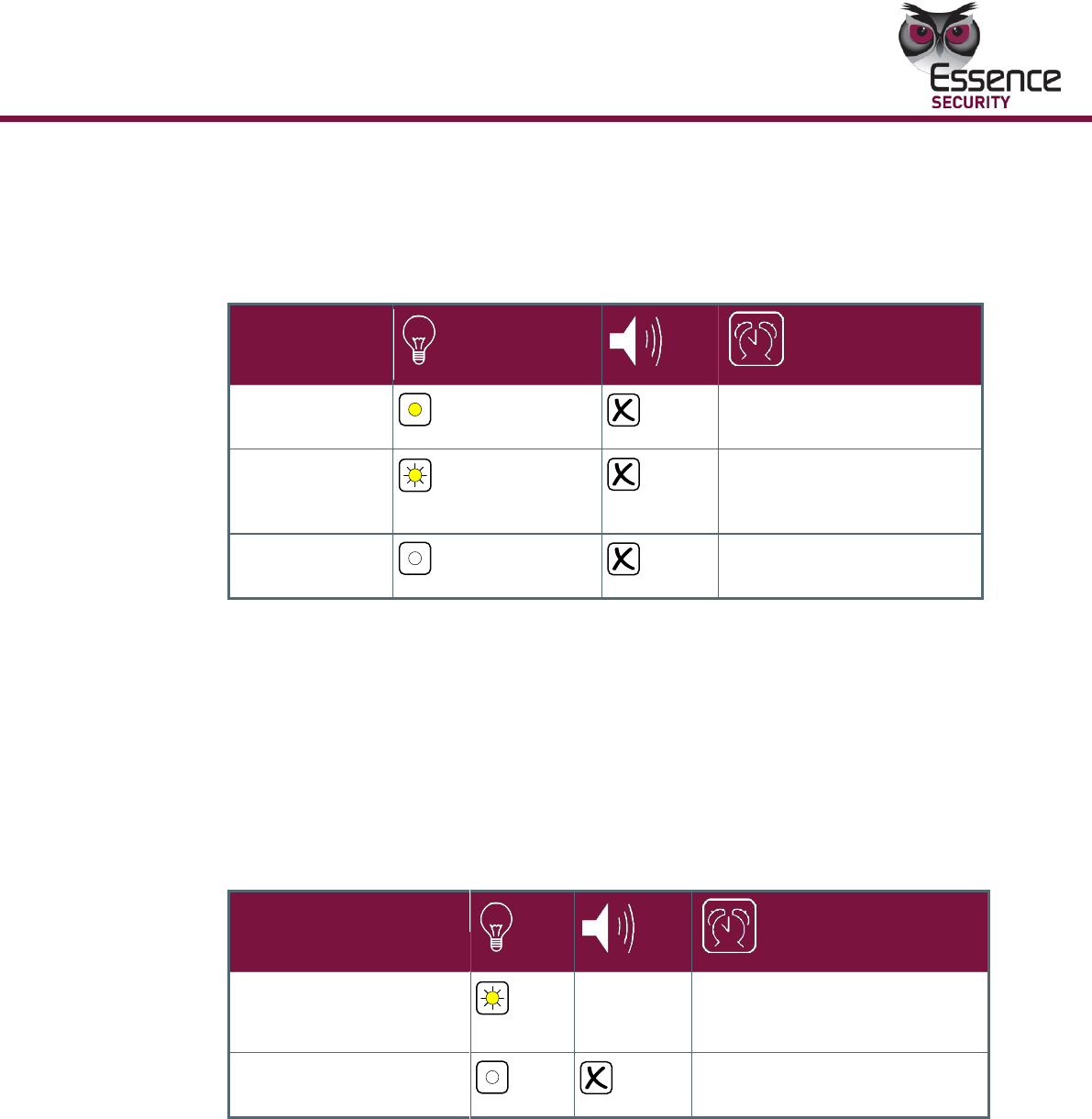
3.2.8 Call Guard function
Pressing on the Call Guard button will dial to the predefined number (Usually the
monitoring center) for a full duplex speakerphone call.
A single status LED provides the Call Guard status information. An Audible “good
beep” is sounded when the Call Guard is engaged. An Audible “bad beep” is
sounded when the Call Guard is disengaged. The table below details the Call
Guard status indicators of the ES7000EG control unit.
Table 11: Call Guard Status Indicators
Call Guard Engaging
Yellow
Good beep
While call guard call is in
process
Call Guard is
Disengaged
Off
While call guard call
disengaged
Operation
28
EverGuard Control Panel
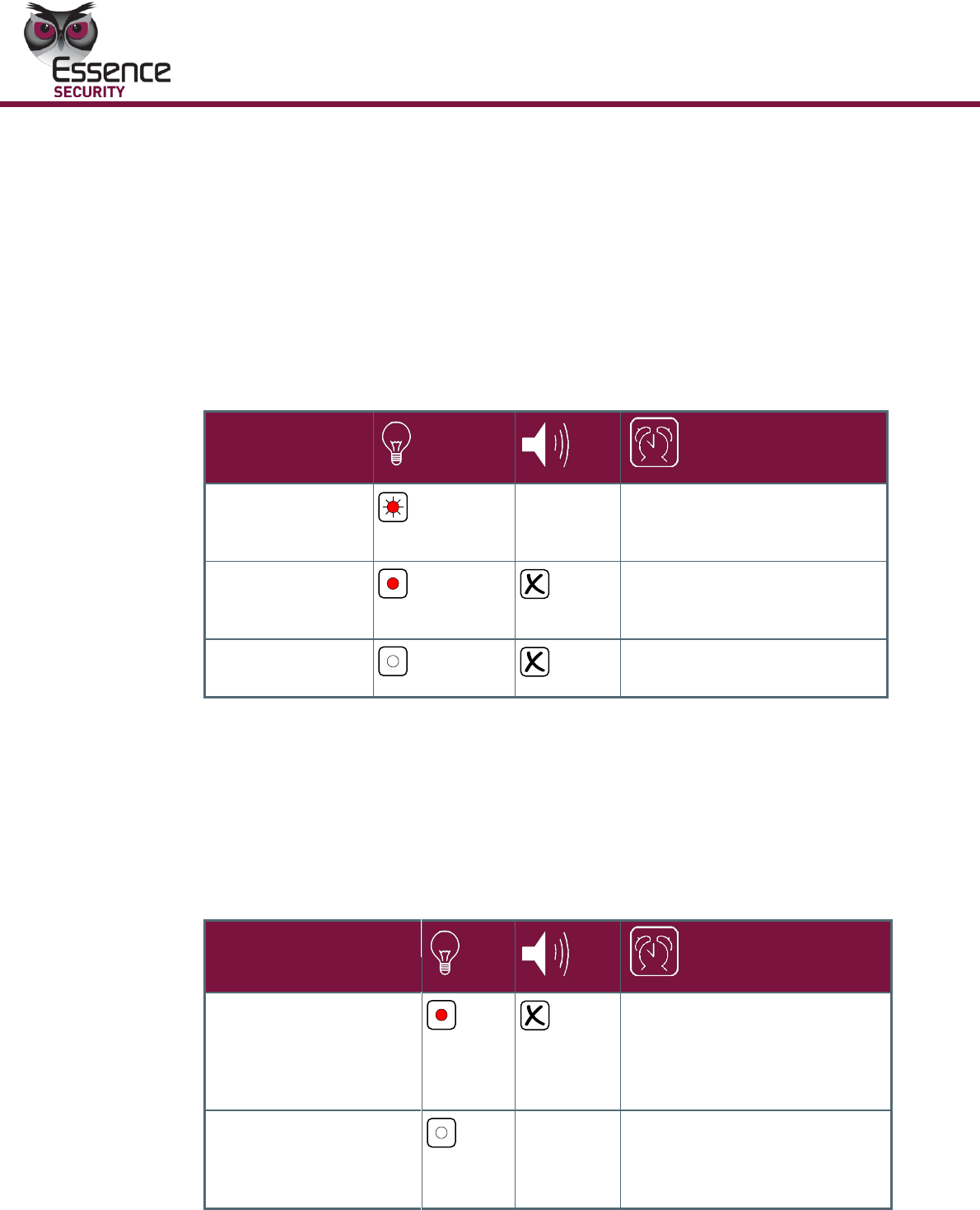
3.2.9 S.O.S function
In case of emergency, the user should press on the S.O.S button and then the
system will notify the central monitoring station.
When the LED stays permanently red it means that the S.O.S signal has been
received correctly.
A single status LED provides the S.O.S status information. An audible S.O.S beep
is sounded to indicate acknowledgement when an S.O.S message is sent. The
table below details the S.O.S status indicators of the ES7000EG control unit.
Table 12: S.O.S Status Indicators
Sending
Message
Red
Flashing
S.O.S beep
The period between engaging
S.O.S and receiving ACK for
the message
S.O.S State,
After Receiving
ACK
Red
After receiving ACK, for S.O.S
message, before verification
call
No S.O.S
Off
When no S.O.S is
engaged/after verification call
3.2.10 Monitoring Station Status
A single status LED provides the Monitoring Station general status. An audible
“good beep” is sounded when the Monitoring Station button is pressed. The
table below details the Monitoring Station status indicators of the ES7000EG
control panel.
Table 13: Monitoring Station Status Indicators
Call Monitoring
Station Request
Red
After receiving message
requesting to connect the
Monitoring service by pressing
the Monitoring Station
button
Calling Monitoring
Station/No
Monitoring Station
Request Received
Off
Good beep
After pressing Monitoring
Station button/no call request
is sent
Operation
EverGuard Control Panel
29
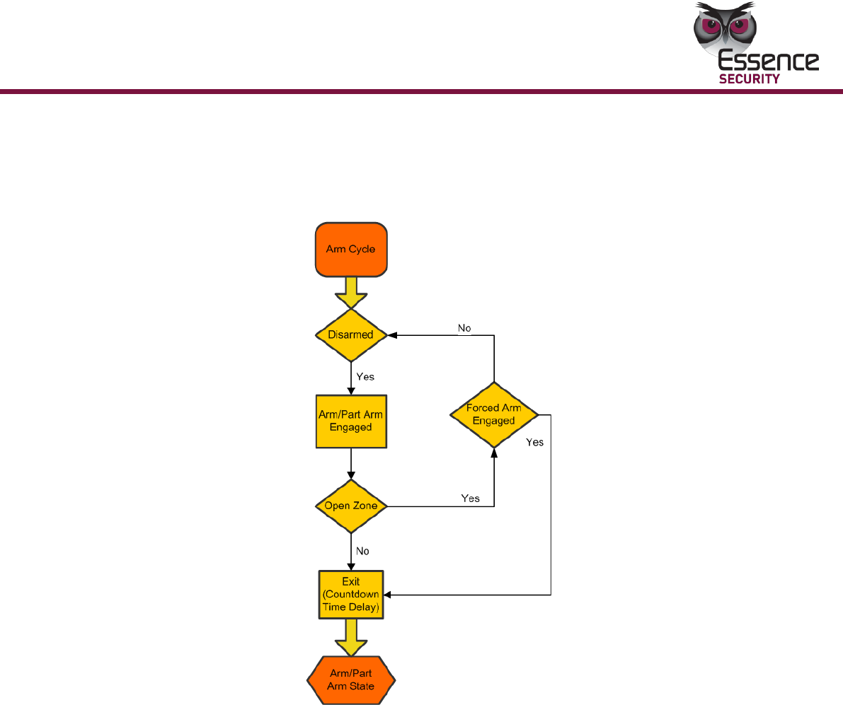
3.2.11 Detailed Operation and Modes
3.2.11.1 The Arm Cycle
The diagram below illustrates the phases of the Arm cycle.
Operation
30
EverGuard Control Panel
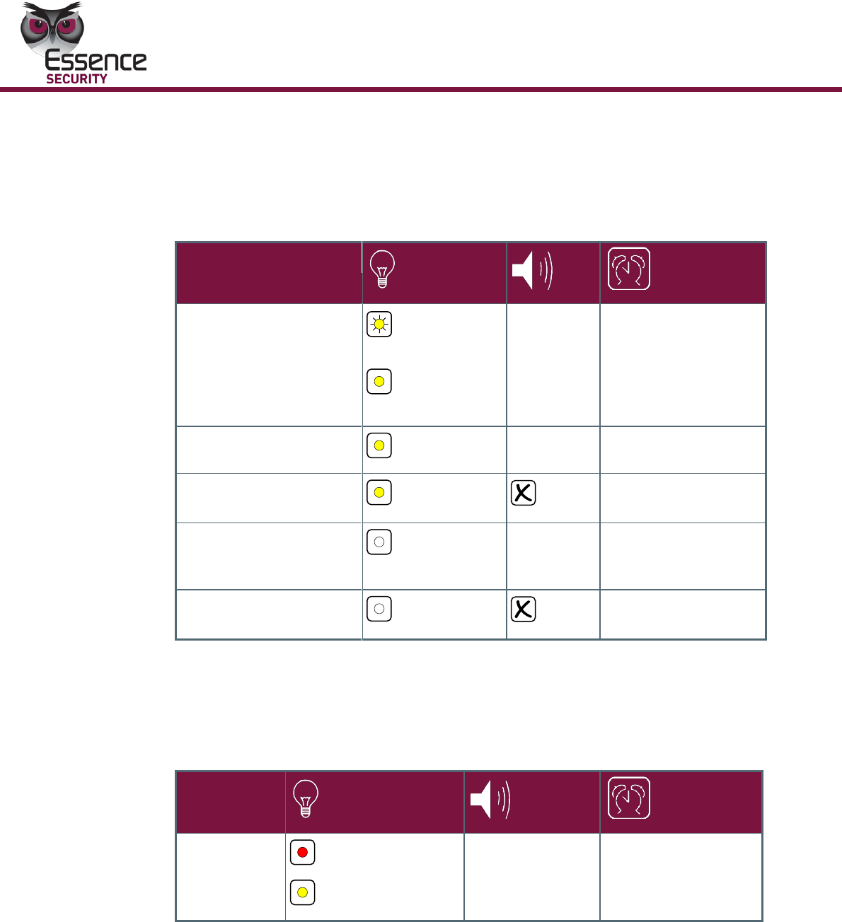
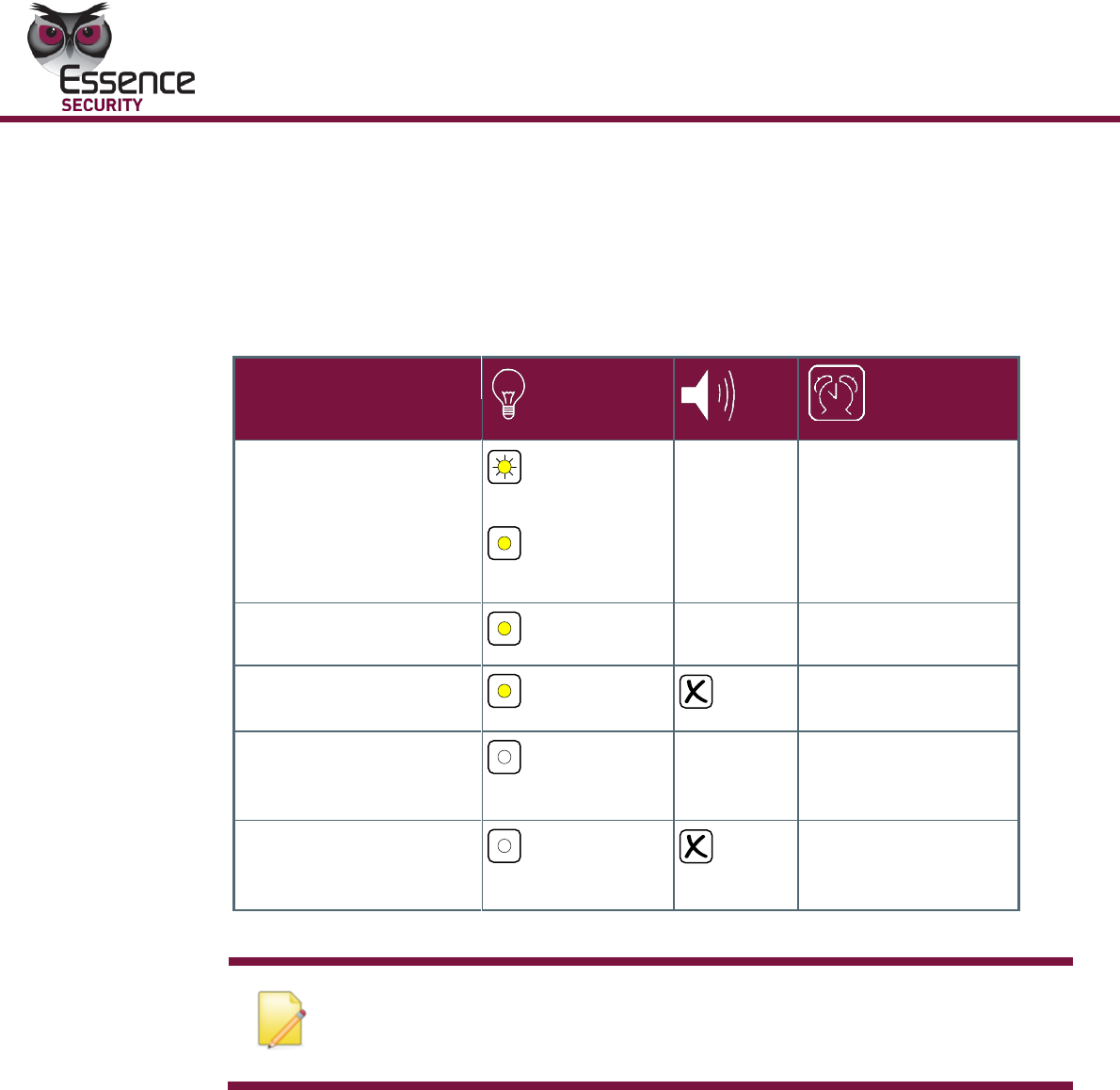
3.2.12 Maintenance
A singe Maintenance LED provides the system status when the ES7000EG control
panel is set to Maintenance mode. When the communications mini USB connecter
is attached or detached, an audible beep is sounded.
Table 14: Maintenance Related Indicators
Attach Indication/
During Installation
Yellow - open
zone
Yellow- call
guard
Attach
beep
After attachment,
connection is
identified
Fault Attached State
Yellow
Bad beep
After plug-in failure
End Install Performed
Yellow
After successful
installation
Detached Without
Preceding “End
Install”
Off
Detached
beep
After detach, without
performing “end
install”
Detached preceding
“End Install”
Off
“End install”
preceding time-out
3.2.13 No Default
The LED combination in the table below indicates a non-operational mode in
which the panel is not in operational mode or is missing default parameters.
Table 15: Non-operational mode indicators
No Defaults
Indication
Red - fault
Yellow - open zone
No defaults beep
While no default
parameters were
downloaded
Operation
EverGuard Control Panel
31
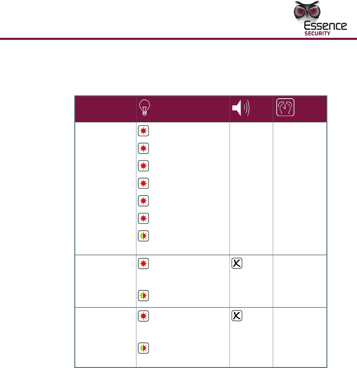
3.2.14 Alarm
A single LED indicates the Alarm status activated when an alarm is triggered. An
audible alarm is sounded.
Table 16: Alarm Status Indicators
Alarm in Process
Red Flashing - S.O.S
Red Flashing - call guard
Red Flashing - arm
Red Flashing - open zone
Red Flashing - fault
Red Flashing - GSM
Red/Yellow Flashing –
power
Alarm
While alarm is in
progress, its
duration could
be configured
by CMS
Arm After Alarm
Red Flashing - S.O.S,
call guard, arm,
open zone, fault, GSM
Red Flashing - power
Arm state which
comes after
alarm is no
unset action is
made
Alarm in Memory
Red Flashing - S.O.S,
call guard, arm,
open zone, fault, GSM
Red/Yellow Flashing –
power
Alarm in
memory is
displayed after
single unset
action
Operation
32
EverGuard Control Panel
3.3 Optional Settings and Defaults
You can configure basic parameters for the EverGuard Control Panel using the
Atlas Mobile application and the ESI-CMS applications.
3.3.1 Atlas Mobile Application
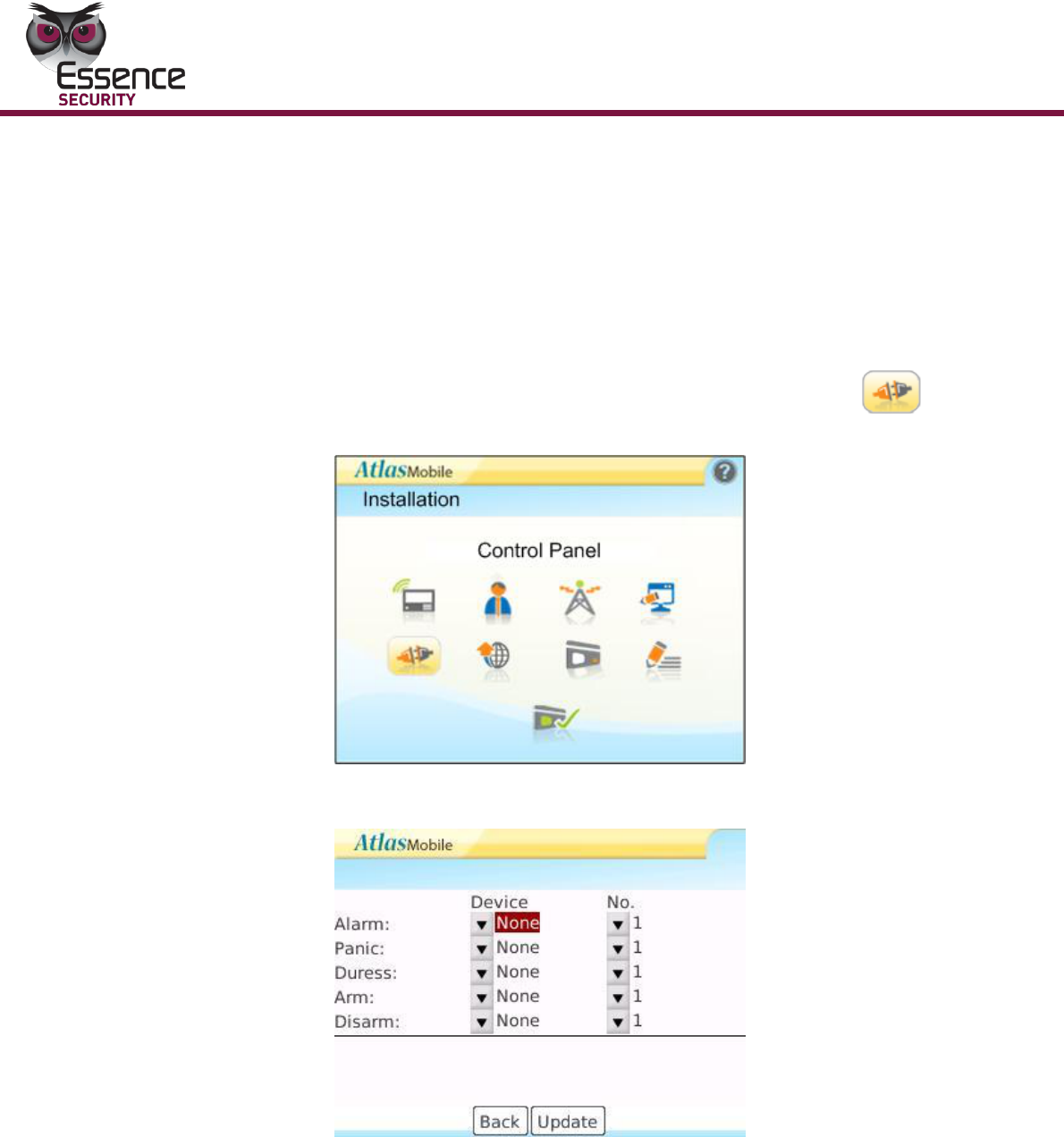
To configure the Control Panel’s automated behavior:
1. On the Installation screen, roll the trackball to the Control Panel
icon.
2. Click. The Installation - Control Panel screen appears displaying the
automated scenarios of the detected EverGuard Control Panel.
3. Roll to the line item to be edited and click. A popup menu appears.
4. Choose which device with corresponding ID No. you want to activate during
each of the five (5) scenarios on the screen.
5. Press the Update button to activate changes.
Operation
EverGuard Control Panel
33
Configuring System and Video Scenarios
When configuring the Security system you must set:
1. Full entry, part entry and exit parameters. These parameters set the
number of seconds
Between entry and keying in the entry pin code.
Between keying in the pin code and exiting before the alarm
sounds.
Auto update of Date and Time – the date and time of the ES7000EG Control
Panel is synchronized with the Blackberry’s system time settings, as well as
with the EGC server and ESI-CMS.
Duress pin code – a code that allows entry into the security area but causes
the control panel to send a distress code to the control center.
Set the Video/Photo Scenarios via the Video/Photo Configuration button.
There are preset scenarios available on the system. Video/Photo can be turned
on and off according to the scenarios selected. At most, two cameras can be
associated with a scenario.
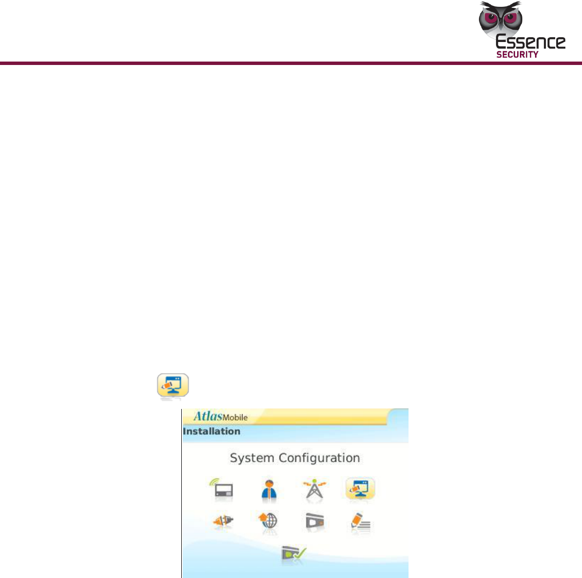
To configure the System:
1. On the Installation screen, roll the trackball to the System Configuration
icon.
Figure 4: ES7000EG System Configuration
2. Click. The System Configuration screen appears.
Operation
34
EverGuard Control Panel
Figure 5: ES7000EG System Configuration Menu
Note: The CPU A and CPU C are Read-Only parameters.
3. For Full and Part, Entry and Exit, roll to the desired parameter. The list of
time duration options appears. The range is 1 to 180 seconds. Note that
for compliance with the EN 50131 standard, both Entry and Exit times
must be set to values of 45 seconds maximum.
4. Click the desired parameter. The selection appears on the screen.
5. To enable Auto-Update of Date and Time, roll to the required checkbox and
click. The option is marked and synchronization of date and time between
the ES7000EG Control Panel and the Blackberry’s systems date and time
settings is enabled.
6. Roll to Duress Pin-Code: and enter the four-digit code to be designated
as the Duress Pin code on the control panel.
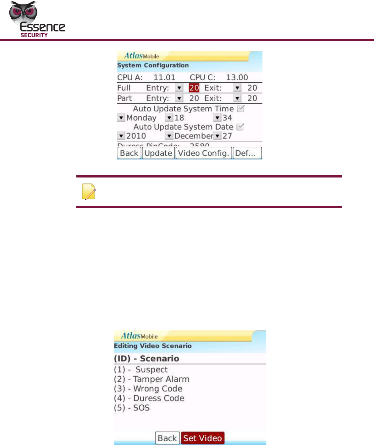
7. Click Video Config The Editing Video Scenario screen appears with a list of
the available scenarios.
Figure 6: Editing Video Scenario
8. Roll to the desired scenario and change what you want.
9. Click Update. You are prompted to save the changes.
Operation
EverGuard Control Panel
35
10. Click Save. A progress screen appears.
11. When processing is complete a message appears stating that the record
was updated successfully. Click OK.
12. The Editing Video Scenario Screen reappears.
13. Click Back to return to the System Configuration Screen.
14. Click Back to return to the Installation Screen.
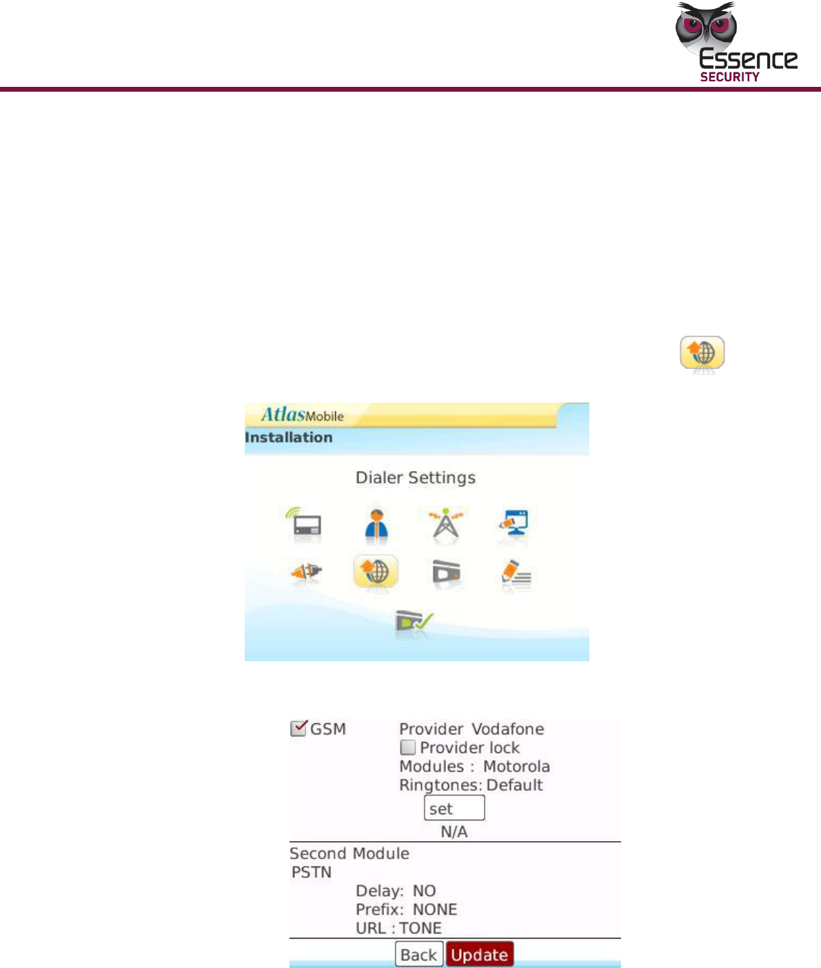
To configure the Dialer Settings:
The Control Panel communicates with the Control Center via GSM (Cellular
Telephone).
1. On the Installation screen, roll the trackball to the Dialer Settings
icon.
Figure 7: ES7000EG Dialer Settings
2. Click the icon. The Editing Dialer Settings screen appears.
Figure 8: Dialer Settings Configuration
3. For GSM click the GSM checkbox.
4. Roll to Provider and click. The list of available service providers appears.

Operation
36
EverGuard Control Panel
5. Select the desired provider and click. The selected provider is listed on the
screen and a predefined dialing sequence is added.
6. A selection of at least one communication channel is mandatory. A pop up
message will appear in case of no communication channel is chosen.
7. Roll to Delay and choose yes or no.
8. To add a required dialing prefix, roll to Prefix and click. Select the prefix
from the dropdown.
9. Enter the required prefix digits and click. The prefix digits appear on the
screen.
10. Click Update. You are prompted to save the changes
To Edit the Dialer Settings:
1. On the Installation screen, roll the trackball to the Dialer Settings
icon.
2. Click the icon. The Editing Dialer Settings screen appears.
3. Modify the settings as in the procedure for configuring Dialing Settings.
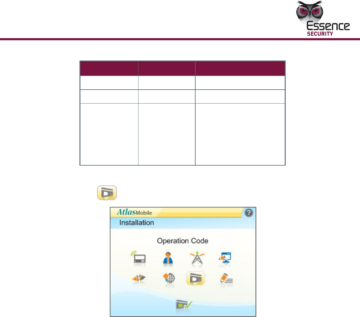
To enter the Operation Code:
Configuring the Operation Code is only available to control panels that have not
yet been set to operating mode (CCS).
The following Operation Codes are used in the system:
Operation
EverGuard Control Panel
37
Table 17: Operation codes
Status
Description
Trigger
NTS
Set up
Preset
ITS
Testing
End Installation
CCS
Operating
Panel activation by:
1. Monitoring station
operation
(command)
2. ESI-CMS
3. Blackberry®
The operation codes are set on the control panel depending on the trigger.
1. On the Installation screen roll the trackball to the Operation Code
icon.
Figure 9: ES7000EG Operation Code
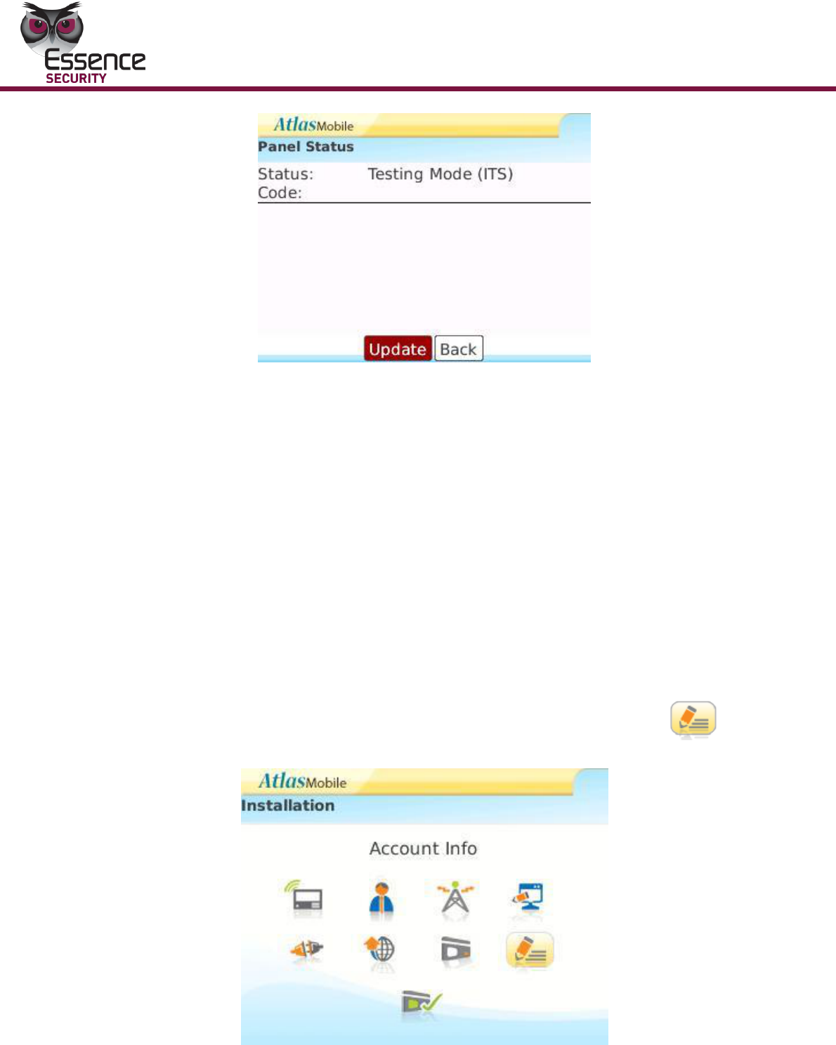
2. Click. The Panel Status screen appears displaying the currently
implemented mode.
Operation
38
EverGuard Control Panel
Figure 10: Atlas Mobile Panel Status
3. Roll to Code and Click.
4. Enter the 4 digit activation code.
5. Click Update.
6. A message appears stating whether or not the activation code was
accepted and stating the current status of the system.
7. Click OK.
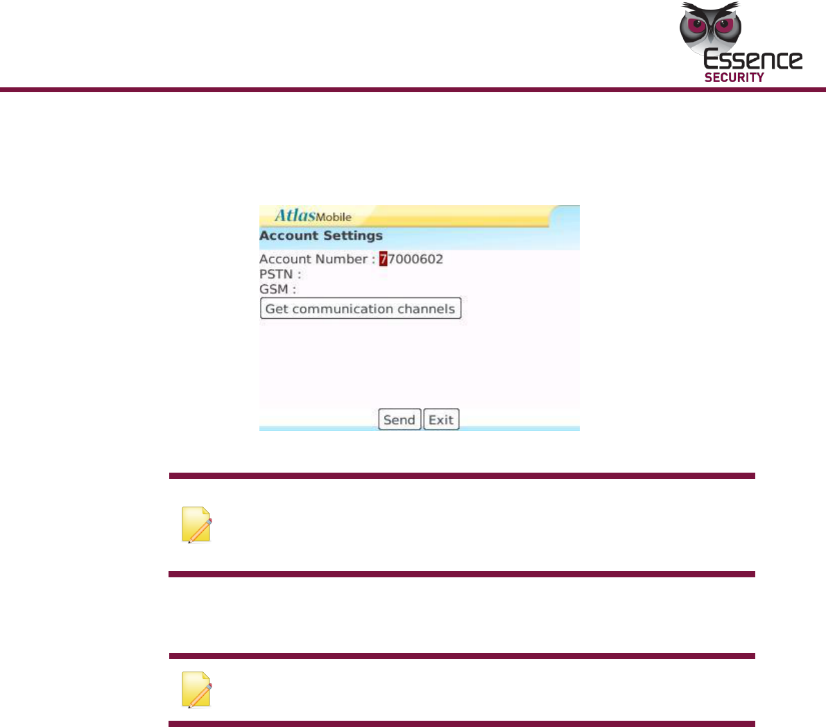
To configure the Account Information:
The Account Number identifies the customer to the control center. The default
settings of a new panel define the Account Number as 0. A Red message is
displayed stating DTMF not received.
The GSM phone number on the account info screen is the one that the monitoring
station uses to contact the panel.
1. On the Installation screen, roll the trackball to the Account Info
icon.
Figure 11: ES7000EG Account Info
Operation
EverGuard Control Panel
39
2. Click. The Account Settings screen appears. This screen appears automatically
only for new control panels that have not yet been assigned an account
number.
Figure 12: ES7000EG Account Settings
Note: In order to check the account number and GSM phone number for
configured control panels, click the account info button to access this
screen manually. If this information does not appear automatically, click
Get communication channels button.
3. Roll to Account Number and enter the Customer Account Number
4. Click send. The system connects the control center to the new panel. This
may take a few seconds.
Note: You need to set at least one communication option (GSM) before
you can click send.
5. Click Send to generate a new DTMF code that is sent to the database. A
notification message is displayed on the screen confirming this action.
6. When complete, press the exit button (or back) and you are returned to
the main screen.
To configure the User Settings:
Different types of users can be defined with different permissions regarding
access to the secured area. Each user is assigned a unique pin number and entry
settings.
The available option combinations are listed in the table below.
Operation
40
EverGuard Control Panel
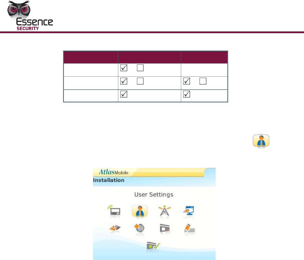
Table 18: User types
Type
Attendance
Temporary
Master
or
Not available
Standard
or
or
Access Only
Attendance – keeps track of access (entrances and exits) in a log on the panel
that is sent to the control center. This log can be accessed at a later date.
Temporary – limits the number of times a user can access the secured area.
1. On the Installation screen, roll the trackball to the User Settings
icon.
Figure 13: ES7000EG User Settings
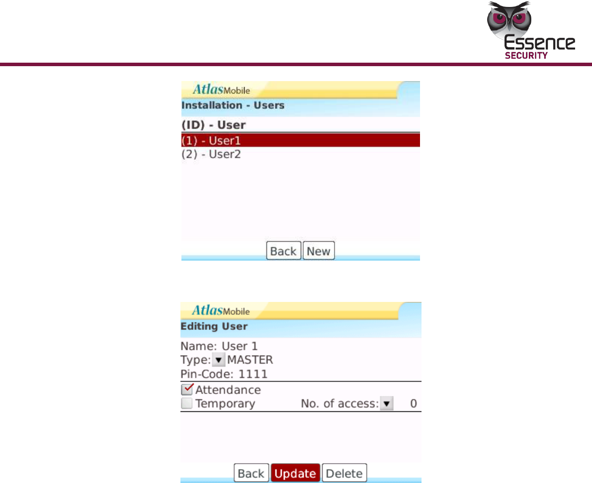
2. Click. The Installation – Users screen appears with a list of Users currently
defined in the system displayed.
Operation
EverGuard Control Panel
41
Figure 14: Installation - Users
3. Roll to New and click. The Editing User screen appears.
Figure 15: Editing User
4. Roll to Name and type in the name of the user.
5. Roll to Type and click. The list of Type options appears:
Master
Standard
Access Only
6. Roll to the desired option and click. The selected Type appears on the
screen.
7. Roll to Pin-Code and enter the users chosen Pin code.
8. Roll to and click the Attendance check box.
9. If applicable, roll to and click the Temporary check box. A list of numbers of
access options appears. The range is 1 to 255.
10. Roll to the desired number and click. The selected number of accesses
allowed appears on the screen.
11. Click Update. You are prompted to save the changes.
12. Click Save. A progress screen appears.

Operation
42
EverGuard Control Panel
13. When processing is complete a message appears stating that the record
updated successfully. Click OK.
14. The Installation – User Screen reappears with the new user highlighted.
15. Click Back to return to the Installation Screen.
To Edit a User:
1. On the Installation screen, roll the trackball to the User Settings
icon.
2. Click. The Installation – Users screen appears.
3. Roll to the line item to be edited and click. A popup menu appears.
4. Roll to Edit and click. The Edit User screen appears.
5. Modify the parameters as in the procedure for adding a new User (follow
the procedure for adding new user as outlined above).
To delete a User:
1. On the Installation screen, roll the trackball to the User icon.
2. Click. The Installation – Users screen appears.
3. Roll to the line item to be deleted and click. A popup menu appears.
4. Do one of the following:
Select Delete.
Select Edit. The Editing Users screen appears. Click Delete.
5. You are prompted to confirm the delete. Click Delete. You are returned to the
Installation – Users screen. The device is deleted.
3.3.2 ESI-CMS Application
To initially connect to the ES7000EG control panel:
For the initial configuration, connect to the control panel via either a direct
connection or a wireless connection.
For a direct connection, use a standard mini-USB to serial cable to connect
between the control panel and the computer or laptop (not provided).
For remote communication use a GSM or GPRS connection.
Once the communication is established between the ESI-CMS software and the
ES7000EG control panel, the control panel’s existing parameters are uploaded
to the ESI-CMS software in the computer. This enables changes to be made
to the configurable parameters that are then downloaded back to the control
panel.
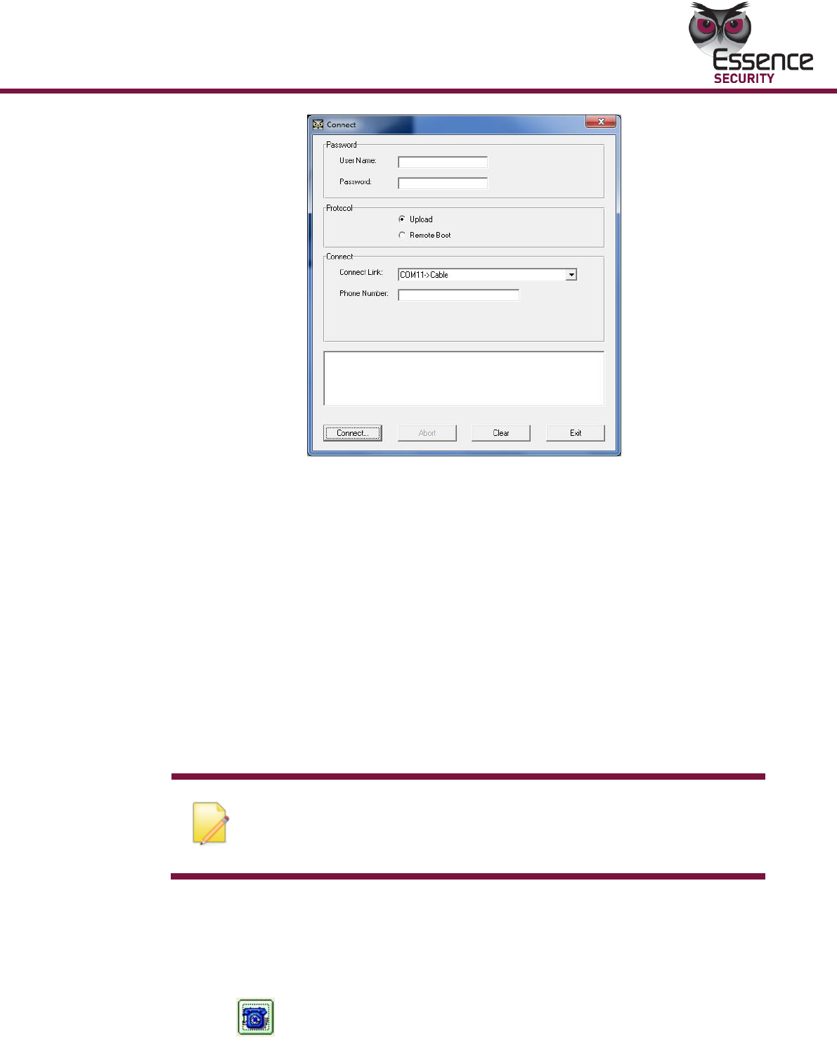
1. Initialize the ESI-CMS application. The Connect dialog box appears.
Operation
EverGuard Control Panel
43
Figure 16: Connect Screen
2. Leave the Username and Password fields empty.
3. Under Protocol, select the radio button for:
Upload -to make either a direct and remote connection to the ES7000EG
control panel in order to change configuration
Remote boot - to make a remote connection to a deployed ES7000EG
control in order to update firmware
4. Open the Connect Link dropdown menu, which opens a list of available ports
for different communication channels. Select the desired option.
5. If a GSM connection is selected, type in the appropriate telephone number in
the Phone Number field.
6. Click Connect. Loading progress information appears in the message section
at the bottom and the Panel Info dialog box is displayed.
Note: When making a direct connection, if a timeout occurs and the
connection is not established, or if you need to exit and reenter the
ESI-CMS, you must unplug the mini USB from the control panel and
then reconnect it. The connection can then be reestablished
To Connect to a Control Panel if the application is already
running
1. From the Link menu select Connect or
Click . on the toolbar. The Connect dialog box appears.
2. Follow the initial connection instructions as above.
Operation
44
EverGuard Control Panel
To download the new configurations to the ES7000EG Control
Panel:
From the Remote Panel menu, select Download or
Click from the toolbar. The changed configurations are downloaded to
the control panels.
To disconnect from an ES7000EG control panel:
1. From the Link menu select Disconnect or
Click on the toolbar.
2. To confirm the disconnection, click OK. You are notified that the End of
Communication is approved by the Control Panel. The connection to the
ES7000EG control panel is closed.
To access the panel information:
The Panel Info dialog box displays the current settings of the ES7000EG control
panel to which the ESI-CMS is currently connected. Most of the information is
read-only. Using this screen, you can set the Communication mode, Arm/Disarm
the ES7000EG control panel, refresh the data, and upload the configuration from
the ESI-CMS to the panel.
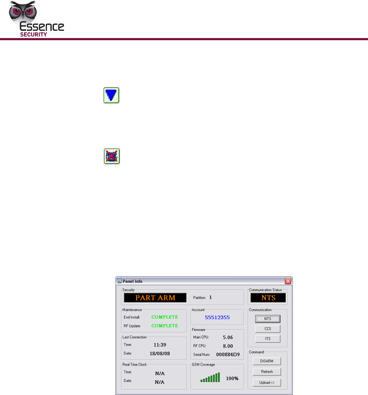
1. From the Options menu, select Panel Info. The Panel Info dialog box
appears. The following information is displayed:
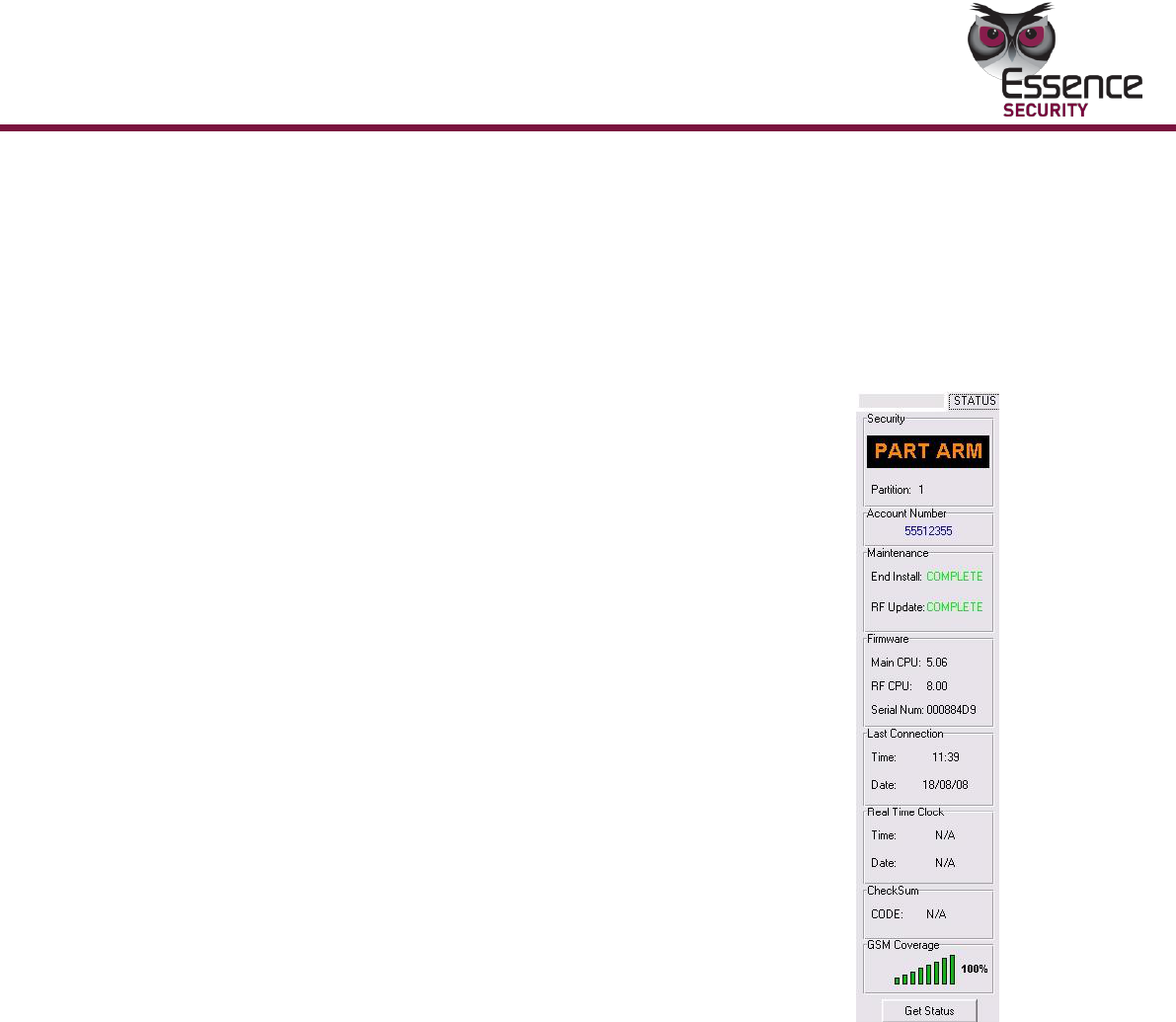
Figure 17: Panel Info Dialog Box
Security
System status
Arm – the system is fully armed
Part Arm – the designated partition is armed
Disarmed – the system is disarmed

Operation
EverGuard Control Panel
45
Partition – In Part Arm mode, indicates the number of the partition that
is armed
Communication Status – Communication mode in operation
NTS - no transmission status
CCS - continuous cycle status (default setting and after activation)
ITS - test mode, used by the technician during initial panel configuration,
modification, or upgrade
Note: The test mode remains in effect for only two hours. It will
automatically revert to its previous state if a new a state is not manually
selected or if an operative code is not sent.
Maintenance - status of the last software update
End Install – Complete = successful update
RF Update – Complete = successful update
Account – ES7000EG Control Panel ID number
Communications – Sets the desired Communication mode (See
Communication Status above)
NTS
CCS
ITS
Last Connection
Time – the time when the ESI-CMS was last connected to this particular
ES7000EG control panel
Date - the date when the ESI-CMS was last connected to this particular
ES7000EG control panel
Firmware
Main CPU – firmware version number of the main CPU
RF CPU – firmware version number of the RF CPU
Serial Num - ES7000EG Control Panel serial number
Real Time Clock
Time
Date
GSM Coverage – displays the quality in percentage of the cellular connection
Command
Arm/Part Arm/Disarm – Sets the Security operation mode on the
ES7000EG or ES7000EG Control Panel
Refresh – refreshes the data from the panel
Operation
46
EverGuard Control Panel
Upload – uploads the configuration from the ES7000EG or ES7000EG
Control Panel to the ESI-CMS
2. To exit the Panel Info dialog box, click . You are returned to the main
screen.
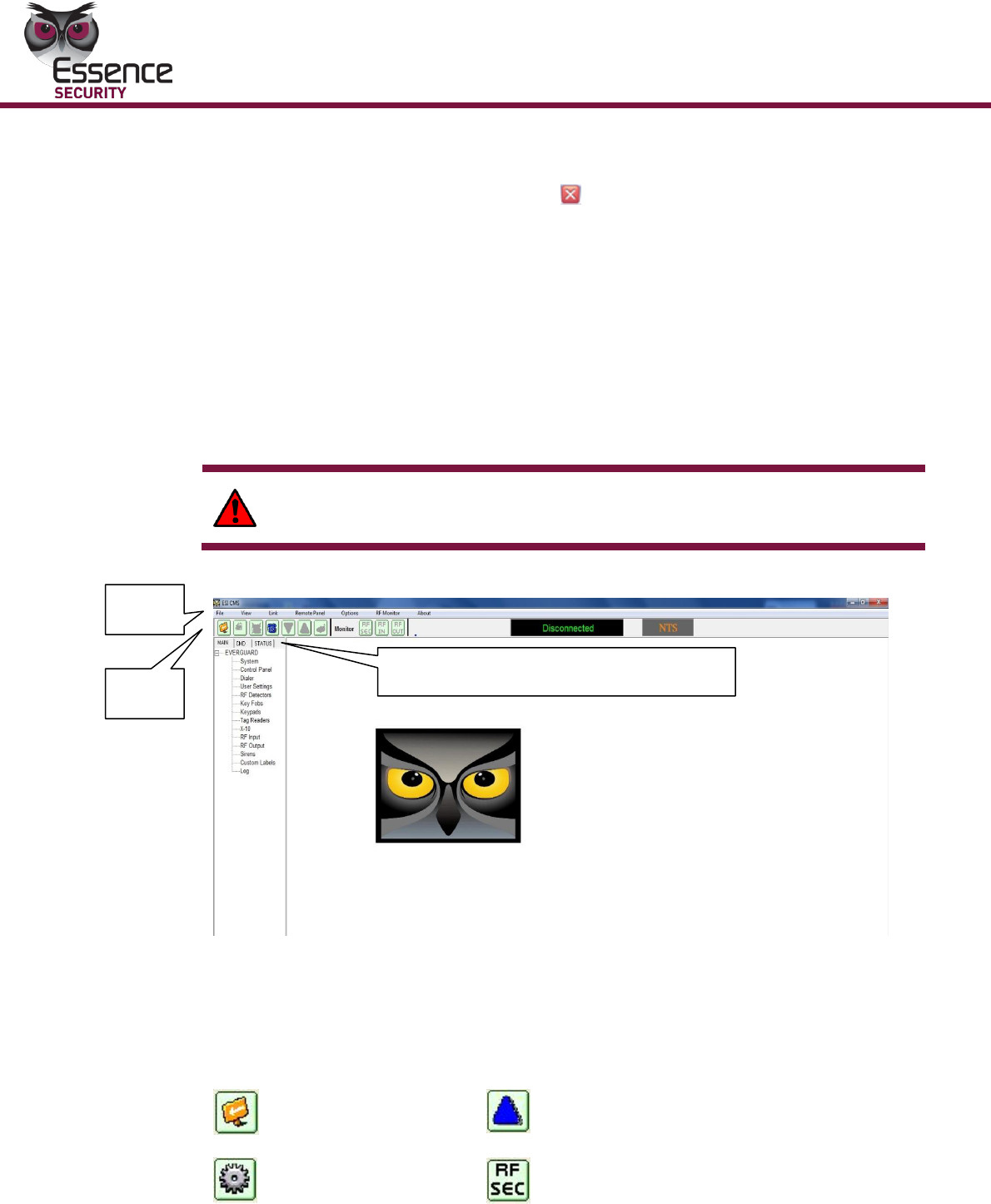
EverGuard Control Panel Main Interface
ESI-CMS main interface contains the following elements:
Menu bar
Toolbar
Status bar
Navigation pane tabs
WARNING! Changes made in the ESI-CMS are NOT automatically applied
to the panel. Any changes MUST be downloaded to the panel.
Figure 18: ESI-CMS Main Interface
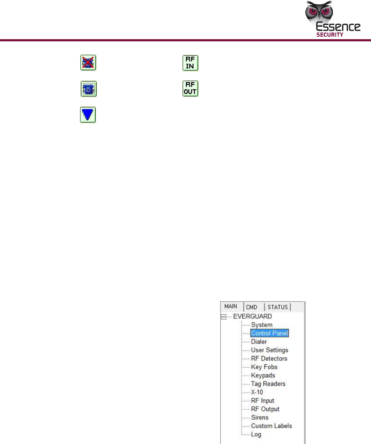
3.3.2.1 Toolbar
The toolbar contains the following buttons:
Exit ESI-CMS
Upload
Properties
RF Security Monitor
Menu
Bar
Tool
Bar
Navigation Tabs
Main Tab, CMD Tab, and Status Tab
Operation
EverGuard Control Panel
47
Disconnect
RF Input Monitor
Connect
RF Output Monitor
Download
The use of these buttons is detailed in the relevant procedures throughout this
document.
3.3.2.2 Status Bar
The Status bar displays the current connection status of the panel,
Connected/Disconnected, as well as the Communication Status:
NTS - no transmission status
CCS - continuous cycle status (default setting and after activation)
ITS - test mode, used by the technician during initial panel configuration,
modification, or upgrade
3.3.2.3 Navigation Pane
The Navigation Pane is comprised of three tabs: Main (default display), CMD and
Status.
3.3.2.4 Main Tab
The MAIN tab of the navigation pane contains links each accessing a category of
parameters. They are:
System
Control Panel
Dialer
User settings
RF Detectors
Key Fobs
Keypads Tag Readers
X-10RF Input
RF Output
Sirens
Custom Labels
Log
Operation
48
EverGuard Control Panel
Note: by default, every screen that is displayed from the navigation
pane contains parameters that cannot be modified until they are
enabled.
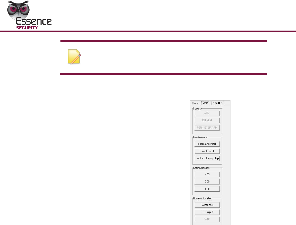
3.3.2.5 CMD Tab
The CMD tab controls many of the
security commands in this single
navigation pane.
It is divided into the following
sections:
Security
Maintenance
Communication
Home Automation
To set the command options via the CMD tab:
1. On the Navigation pane, CMD tab, select Security, and set the Security
mode according to the desired method to secure the designated area. This is
done using remote upload.
Arm – the system is fully armed
Disarmed – the system is disarmed
Perimeter Arm – the perimeter partition is armed
2. Under Maintenance, if the Panel Info dialog box reads INCOMPLETE after a
software update attempt, force the end of a Software update. Click Force
End Installation.
3. To reset the Control Panel, click Reset Panel.
4. Under Communication Status, CCS is the default setting.
5. Under Communication, select one of the following three modes to change
the status in the Communication Status:
NTS
CCS
ITS
Operation
EverGuard Control Panel
49
After any change, press the communication button, and a dialog box appears
to state that the Communication status is being changed.
6. Under Home Automation, to activate a door lock, click Door Lock.
7. To activate an RF Output device, click RF Output.
8. To activate and X-10 device, click X-10.
3.3.2.6 Status Tab
The Status tab contains the same information as is
found on the Panel Information dialog box.
Two additional items in this tab are:
Checksum – displays N/A
This is only relevant for remote boot otherwise it
displays NA
Get Status – refreshes the data in the status
tab
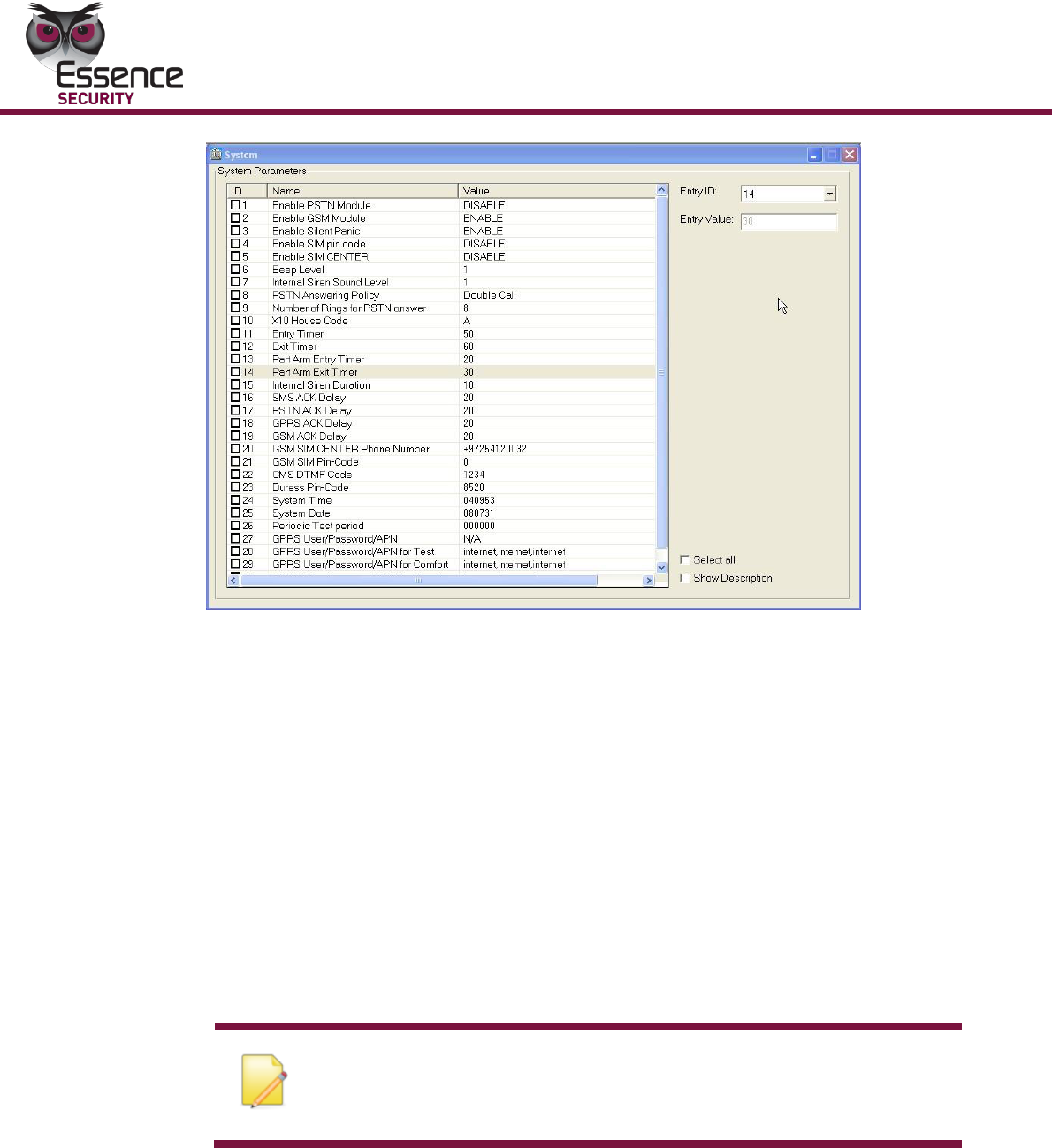
To display System Parameters:
The System parameters screen is a read-only display of the system parameters
and their current settings.
On the MAIN tab of the Navigation pane, click System. The system screen
appears.
Operation
50
EverGuard Control Panel
Figure 19: System Screen
To configure the Control Panel
3.3.2.7 The control panel is divided into several
parameter sets:
Timer Delay – the delay of the alarm when entering/exiting
Sound – the alarm volume and setup
Power – sets the messages sent to the monitoring station after a power failure
Active Output Devices – Device IDs
Password – Duress pin-code and ESI-CMS DTMF code
System Time – Read-only date/time parameters
Transmitter – Wire line or wireless transmission parameters
Note: When the Control Panel screen is initially opened, all
checkboxes are unmarked, and all of the parameters are dimmed and
not configurable. Click the checkbox to enable.
You can also access the following configuration groups via the Control Panel
screen:
Dialer Configuration
GPRS Configuration
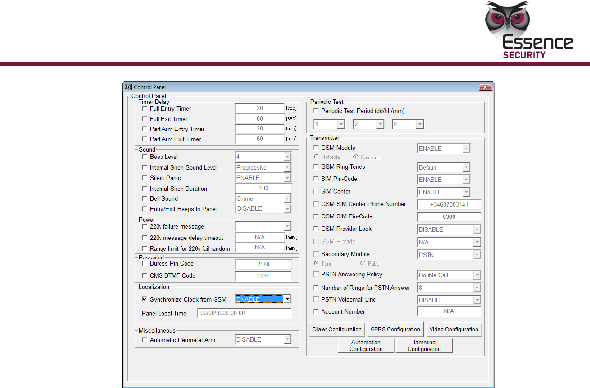
1. On the MAIN tab, click Control Panel. The Control Panel screen appears.
Operation
EverGuard Control Panel
51
Figure 20: Control Panel Screen
2. To edit a specific parameter, mark the relevant checkbox. The parameter is
then enabled and you can modify it.
3. Under Timer Delay, parameters enable you to set the, configure the
entry/exit timed devices using the following Timer Delay parameters:
Full Entry Timer
Full Exit Timer
Part Arm Entry Timer
Part Arm Exit Timer
The valid range for each of these parameters is 1 to 180 seconds.
For compliance with the EN 50131 standard, both Entry and Exit times must be
set to values of 45 seconds maximum.
4. Under Sound, set the sound levels and functions of the alarm for the
following parameters:
Beep Level - The beep level controls the volume of the beep and can be
set from 1 to 7.
Internal Siren Sound Level – The internal siren sound level controls
the volume of the internal siren and can be set from 1 to 9, or it can be
set for Progressive (beginning at a lower decibel and escalates).
Silent Panic – When Silent Panic is enabled, it is not necessary to set
the Beep level or the Internal Siren Sound level.
Internal Siren Duration – Determines the duration that the internal
siren sounds. The Internal Siren duration can be set between 5 to 180
seconds.

Operation
52
EverGuard Control Panel
5. Under Power, set the indicators that notify the monitoring station of power
failure for the following parameters:
Random time for 220v fail indication – Enables or disables the
random time message that is sent to the monitoring station. This sends a
message at random time intervals to the monitoring station along with
the fixed time message. For multiple panels (e.g., in an apartment
building), it is recommended to set random time to send a message.
220v indication delay timeout – Defines the fixed time message to be
sent (in minutes). The master clock, after a delay, sends a message to
the monitoring station regarding a power failure.
Range limit for 220v fail Random - Sets the random message to be
sent (in minutes). This parameter can only be configured if the Random
time for 220V fail indication parameter is enabled. It is recommended
to set this parameter for the value of that set for Random time for
220v fail indication + an additional 5 min.
6. Press the Automatic Configuration button to set the automatic RF output
activation in each of the following system states:
ALARM
PANIC
ARM
DISARM
DURESS
From the Device dropdown list, select one of the following:
X-10 devices - can handle stronger appliances (e.g., washing machine,
etc.)
RF Output devices - generally is set for lights. Assign assigned an ID
number. The range is 1 to 16.
7. Under Password, configure the following codes:
Duress Pin-Code – Enter a 4 digit code to trigger dispatching a duress
message to the control center.
ESI-CMS DTMF Code – Enter a 4 digit code to activate external devices.
8. Localization – Set the source for the control panel real-time-clock. Select
enable to sync with the GSM network clock or disable to sync with the
monitoring station server.
For compliance with the EN 50131 standard, set Synchronize Clock from
GSM to enable.
The Panel local Time parameters are read-only and are drawn from the
system.
9. Set the Periodic Test Period, in days, hours, minutes, how often the system
should send a test message to the control center.
Note that for compliance with the EN 50131 standard, this test should be
enabled and set to a period of not more than 2 hours.
10. Set the Transmitter parameters according to requirements:
GSM Module – Enables or disables the GSM module.
Operation
EverGuard Control Panel
53
Note: If the panel connection has been set to Serial (COM), the
GSM module must be disabled.
SIM Pin-Code - Enables or disables the SIM pin code. When using SIM
cards that are unlocked and do not require a PIN code, the SIM Pin-Code
parameter should be disabled.
SIM Center – Enables or disables the SIM center, which is the cellular
service provider.
GSM SIM Center Phone Number – Defines the SIM Center telephone
number. To add a GSM SIM Center Phone Number, the SIM Center
parameter must be enabled.
GSM SIM Pin-Code – Defines the 4 digit SIM pin-code. To add a SIM
PIN code, the SIM Pin-Code parameter must be enabled.
Account Number - Defines the panel’s account number, when
necessary.
To configure the Dialer Configuration
Using the Dialer Configuration Screen, configure dialer parameters for:
SMS Configuration
GPRS Configuration
GSM DATA Configuration
Cycle Permanent (minutes)
GSM Configuration
Video Configuration
Note: When the Dialer Configuration dialog box is initially opened,
all checkboxes are unmarked, and all of the parameters are
disabled. Click a checkbox to enable it.
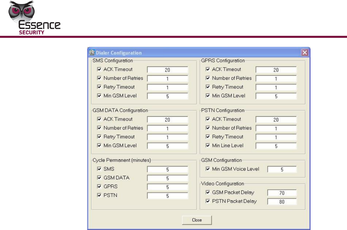
1. On the Control Panel screen, click Dialer Configuration button. The Dialer
Configuration dialog box appears.
Operation
54
EverGuard Control Panel
Figure 21: Dialer Configuration Dialog
2. To edit a specific parameter, mark the relevant checkbox. The parameter is
enabled. You can then modify it.
3. For SMS Configuration, GPRS Configuration and GSM DATA
Configuration set the following parameters:
ACK Timeout –Defines the maximum amount of time (in seconds) that
the system waits to receive an acknowledge message before continuing
to the next dialing option.
Number of Retries – Defines the number of times the dialer redials.
Retry Timeout – Defines the number of minutes the dialer waits before
retrying.
Min GSM Level – Defines the minimum volume level of the GSM.
4. For Cycle Permanent (minutes), set the amount of time in minutes that
the system attempts to connect using the following:
SMS
GSM DATA
GPRS
5. For GSM Configuration, set the Min GSM Voice Level parameter to the
minimum volume level of the GSM voice.
6. For Video Configuration, set the parameters for the GSM Packet Delay
Time (in milliseconds).
7. Click Close. You are returned to the Control Panel screen.
Operation
EverGuard Control Panel
55
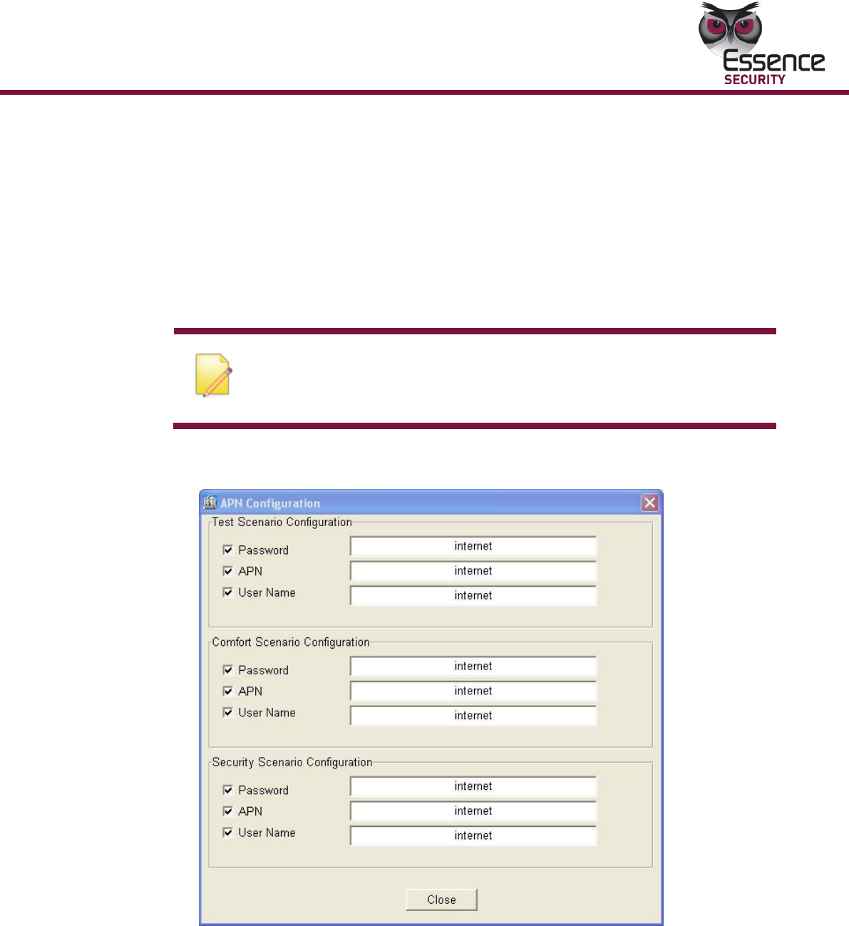
To configure the APN (GPRS) Configuration:
Using the GPRS Configuration dialog box, configure the destination servers for
indoor/outdoor videos. The APN (GPRS) Configuration screen is divided into the
following parameters sets:
Test Scenario Configuration – used during system testing and when
modifying the configuration
Comfort Scenario Configuration – used when the end user tests the device
Security Scenario Configuration – set for normal use
Note: When the GPRS Configuration dialog box is initially opened, all
checkboxes are unmarked, and all of the parameters are dimmed
and not configurable. Click a checkbox to enable the parameter.
1. On the Control Panel screen, click GPRS Configuration button. The APN
(GPRS) Configuration dialog box appears.
Figure 22: APN (GPRS) Configuration Dialog Box
2. To edit a specific parameter, mark the relevant checkbox. The parameter is
enabled. You can then modify it.
3. For the Test Configuration, Comfort Configuration, and Security
Scenario Configuration parameters, define the following:

Operation
56
EverGuard Control Panel
Password – enter the Password received from the local SIM card provider
APN – enter the Access Point Name received from the local SIM card
provider
User Name – enter the User Name received from the local SIM card
provider
4. Click Close. You are returned to the Control Panel screen.
To configure the Video Scenario Configuration parameters:
The Video Configuration dialog box contains the following tabs:
Suspect – RF Input device type
Tamper Alarm – tamper action is detected only from the control panel
Wrong Code – pin code entered five times incorrectly
Duress Code – end user enters the duress code
SOS – end user presses panic button on panel or key fob
IVD/IPD Security – detects movement via indoor video/photo device
Comfort – activated by a comfort command message
Security – activated by a security command message
Perimeter Alarm – detects movement via outside photo device
All Units Scenario – activated by a command message
OPEN/CLOSE – user attendance triggers video/photo upon
arming/disarming
Configuration – general definitions for video/photo
Note: When the Video Configuration dialog box is initially opened,
all checkboxes are unmarked, and all of the parameters are
disabled. Click a checkbox to enable the parameter.
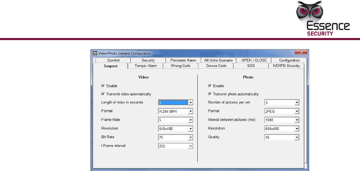
1. On the Control Panel screen, click Video Scenario Configuration button.
The Video Scenario Configuration dialog box appears displaying the
Suspect tab.
Operation
EverGuard Control Panel
57
Figure 23: Video Configuration Suspect Tab
2. To access a specific tab page, click on the appropriate tab.
3. For all tabs (except for the Configuration tab), set the following parameters:
To enable, check the checkbox to activate all parameters underneath.
For Transmit video automatically, check the checkbox to transmit the
video automatically to the monitoring station.
From the Length of video in seconds dropdown list, select parameters
between 5 to 30 seconds.
From the Format dropdown list, select one of the following video formats:
H 264 VES or H 264 MP4
From the Frame Rate dropdown list, select a parameter of between 5 and
30 frame rates.
From the Resolution dropdown list, select one of the following sizes:
640x480, 320x240, 160x120, or 80x60.
From the Bit Rate dropdown list, select a parameter of between 20 and
255 bit rates.
From the I-Frame interval dropdown list, select one of the following
intervals: 5, 10, 15, 20, 30, 45, 60, or 255 I-frame intervals.
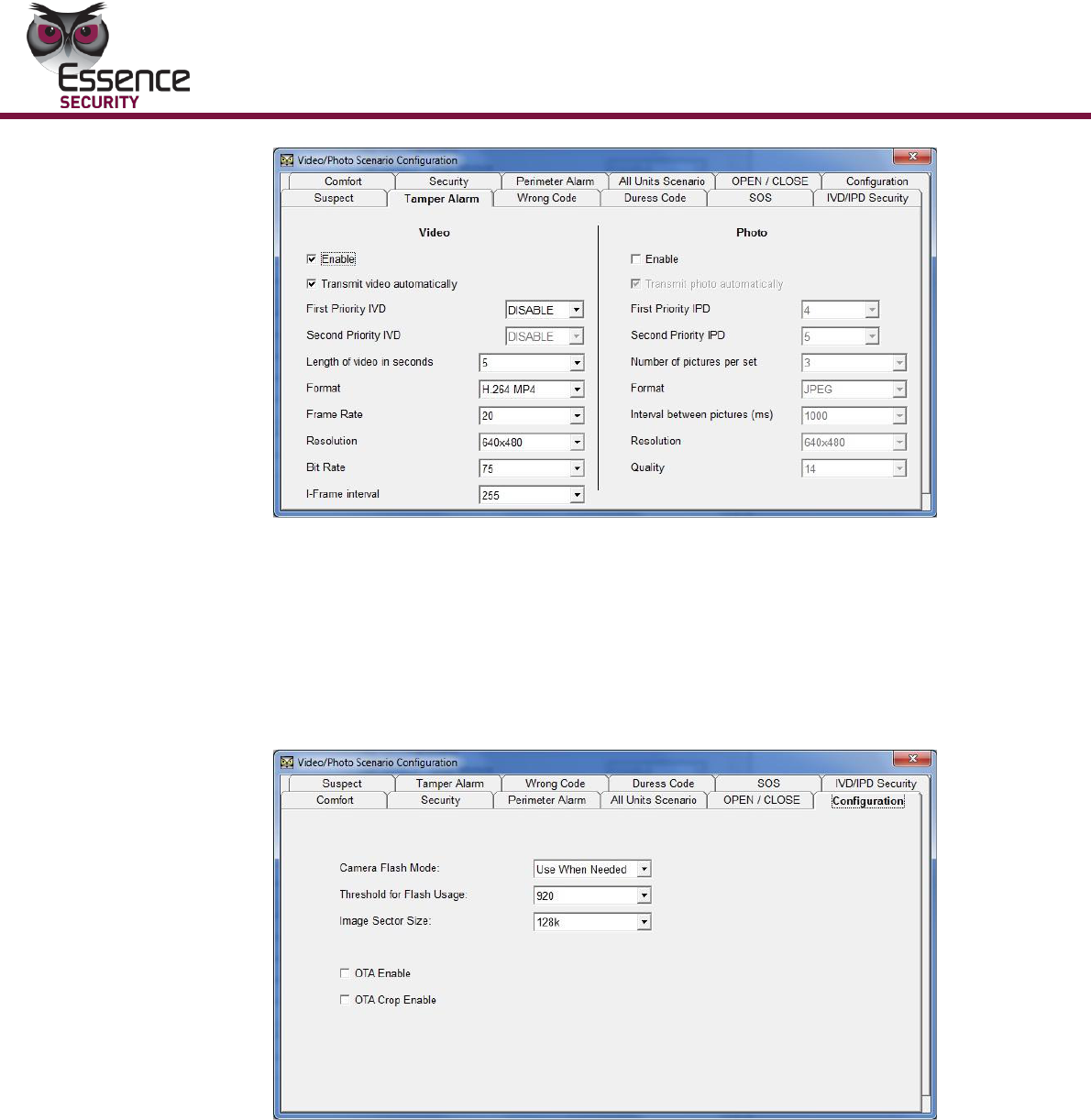
4. For the Tamper Alarm, SOS, and OPEN/CLOSE tabs, set the following
additional parameters:
Operation
58
EverGuard Control Panel
Figure 24: Video Scenario Configuration Screen Tamper Alarm Tab
ID of first IVD associated with scenario
ID of second IVD associated with scenario
Set each to a designated ID device between 1 and 64 that corresponds to the
appropriate IVD devices in the control panel.
5. For the Configuration tab, set the following parameters:
Figure 25: Video Scenario Configuration Screen Configuration Tab
IVD Flash Mode – select one of the following:
Never Use
Use When Needed
Always Use
Threshold for flash usage –set the threshold percentage of the
minimum darkness level. The range is 1-1023%.
Video Sector Size – Select from one of the following sizes:
64k
Operation
EverGuard Control Panel
59
128k
256k
OTA Enable – check to enable object tracking
OTA Crop Enable – check to enable zoom in upon movement detection
Note: OTA Enable and OTA Crop Enable can only be enabled with a
resolution set to 320x240.
6. Click . You are returned to the Control Panel screen.
Caution: If you have not chosen a valid IVD or OVDS, the parameters in
the Video Scenario Configuration tabs cannot be saved.
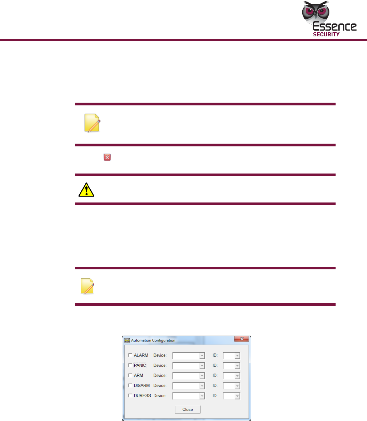
To configure the Automation Configuration:
Using the Automation Configuration dialog box, configure the device and ID of the
automated actions.
Note: When the Automation Configuration dialog box is initially opened, all
checkboxes are unmarked, and all of the parameters are dimmed and not
configurable. Click a checkbox to enable.
1. On the Control Panel screen, click Automation Configuration button. The
Automation Configuration dialog box appears.
Figure 26: Automation Configuration Dialog Box
2. To edit a specific parameter, mark the relevant checkbox. The parameter is
enabled. You can then modify it.
3. For each automatic re-action parameter, define the following:
Operation
60
EverGuard Control Panel
Device – select a device or a protocol from the dropdown list.
The list groups peripherals that use the X10 and RF Output protocols.
These protocols are set in the relevant Main tab category. Door Lock is an
independent action not grouped by protocol.
ID – enter the identification number of a peripheral assigned in the
relevant Main tab.
4. Click Close. You are returned to the Control Panel screen.
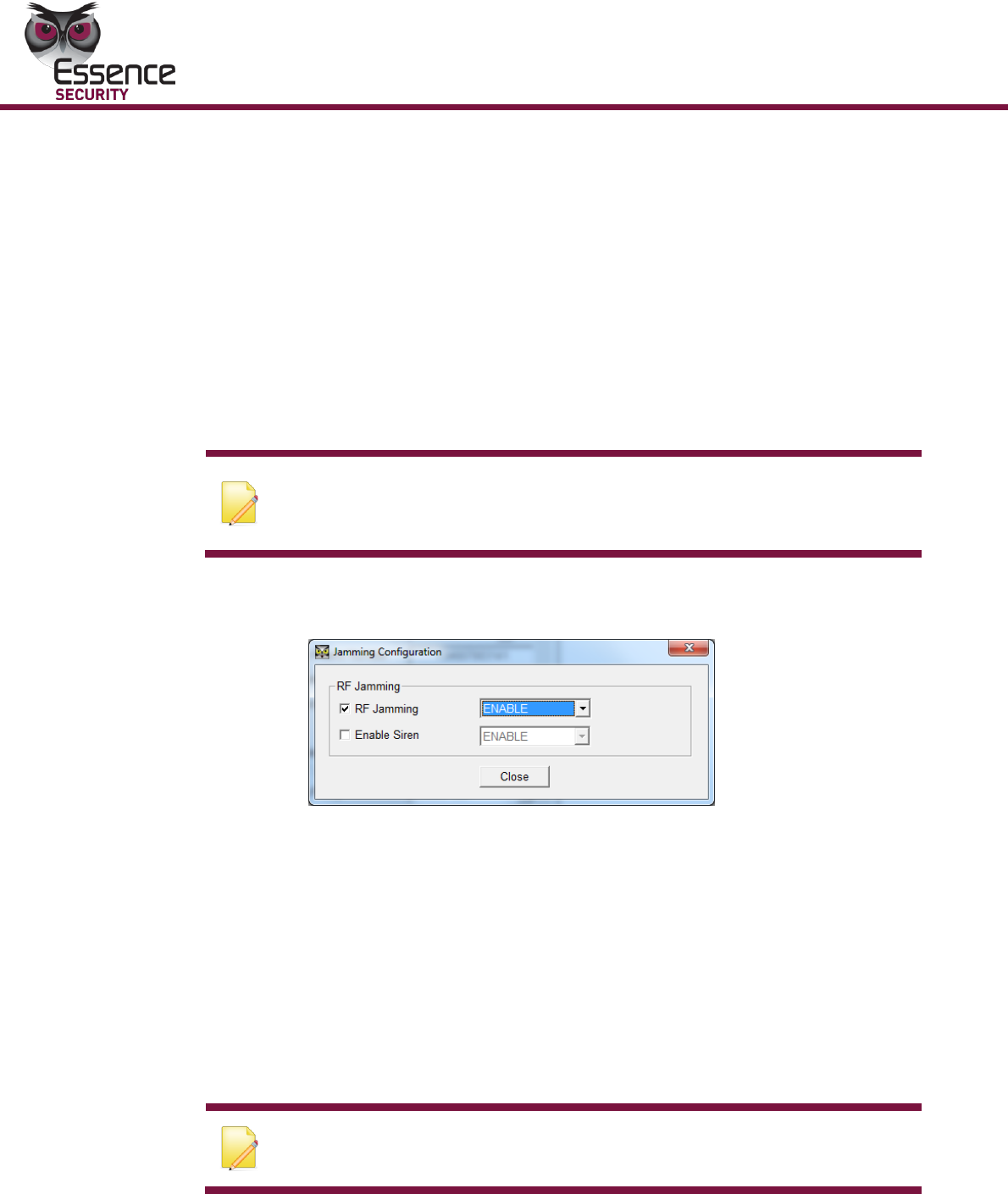
To configure the Jamming Configuration:
Using the Jamming Configuration dialog box, configure the action taken where a
jamming signal is detected.
Note: When the Automation Configuration dialog box is initially opened, all
checkboxes are unmarked, and all of the parameters are dimmed and not
configurable. Click a checkbox to enable.
1. On the Control Panel screen, click Jamming Configuration button. The
Jamming Configuration dialog box appears.
Figure 27: Jamming Configuration Dialog Box
2. To edit the Jamming parameter, mark the relevant checkboxes. The
parameter is enabled. You can then modify it.
3. Enable jamming detection (Enable or Disable). If enable is selected a reaction
parameter is enabled.
4. Select the Enable Siren re-action checkbox and set the parameter (Enable or
Disable).
Note that the Enable Siren re-action checkbox is only available where
jamming is enabled.
5. Click Close. You are returned to the Control Panel screen.
Note: For compliance with the EN 50131 standard, jamming detection
must be enabled.
Operation
EverGuard Control Panel
61
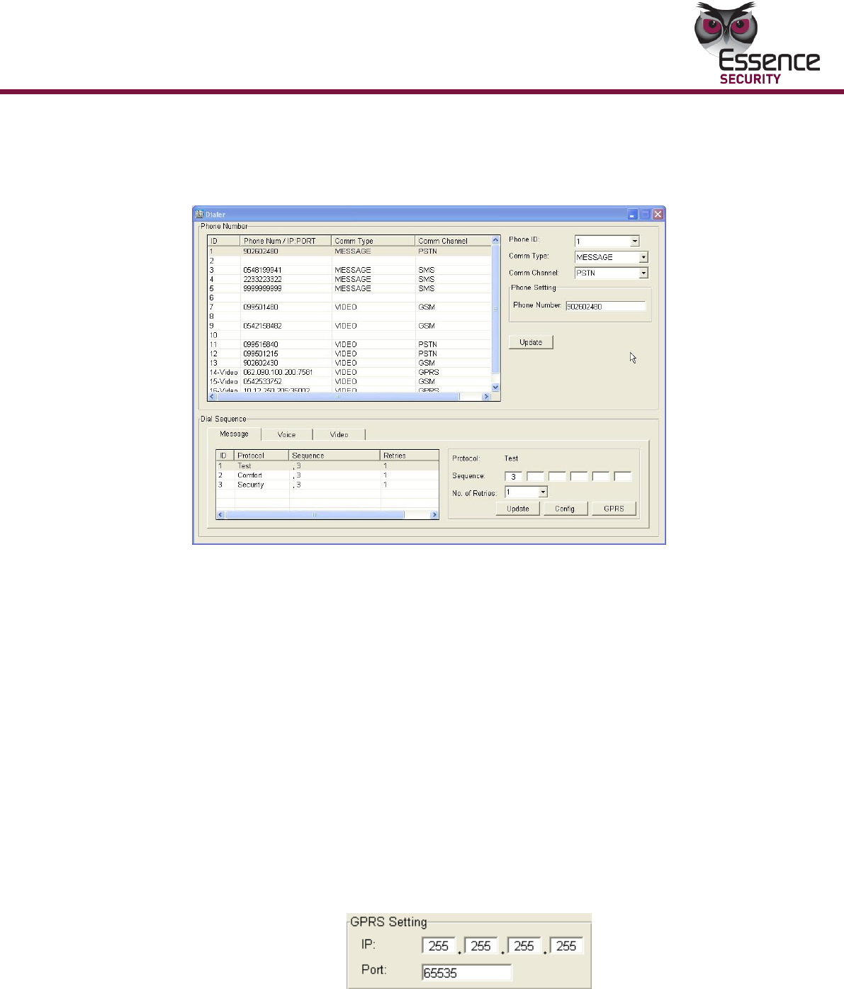
To configure the Dialer:
Using the Dialer Screen, set the dialing ID options
1. On the MAIN tab, click Dialer. The Dialer screen appears.
Figure 28: Dialer Screen
2. Under Phone Number, select a line item or from the Phone ID dropdown
list, select one of the thirteen dialing IDs or three video IDs to change the
information.
3. From the Comm Type dropdown list, select one of the following types:
VIDEO
VOICE
MESSAGE
4. From the Comm Channel dropdown list, select one of the following:
If VIDEO is selected, choose GSM or GPRS
If VOICE is selected, choose GSM
If MESSAGE is selected, choose GSM, SMS or GPRS
5. For GSM or SMS the Phone Setting is enabled. Enter the phone number that
the ID should dial.
For GPRS the GPRS Setting is enabled. Enter the IP address and port.
Figure 29: GPRS Setting
6. Click Update. The information displayed in the Phone Number section is
refreshed according to the configured settings.
7. For Dial Sequence, enter the number to which the control center is to dial

Operation
62
EverGuard Control Panel
and specify the number of redial times (specifically with messages, voice, and
video).
Select the Message, Voice, or Video tab to set the configurations.
For Sequence, enter up to six numbers to be called.
From the No. of Retries dropdown list, select between 1 and 8 times to
redial the sequence.
8. Click Update to refresh all of the information displayed in the Dial Sequence
section.
9. To access the Dialer Configuration dialog box, click Config.10.
10. To access the APN Configuration dialog box, click GPRS.
11. Click to return to the Control Panel screen.
Note: For compliance with the EN 50131 standard, also add the home-
owner cellular phone number as the last entry to the dial sequence, so that
if all communication with the monitoring station is lost, he will get an SMS.
This SMS has some encoded data in it and it looks like this:
“ESIP04D010501010199000003000110519005303E#
XDN000020NNNICE19ZL34NIUP00…”.
The only meaning for the user is that the communication with the
monitoring station is lost.
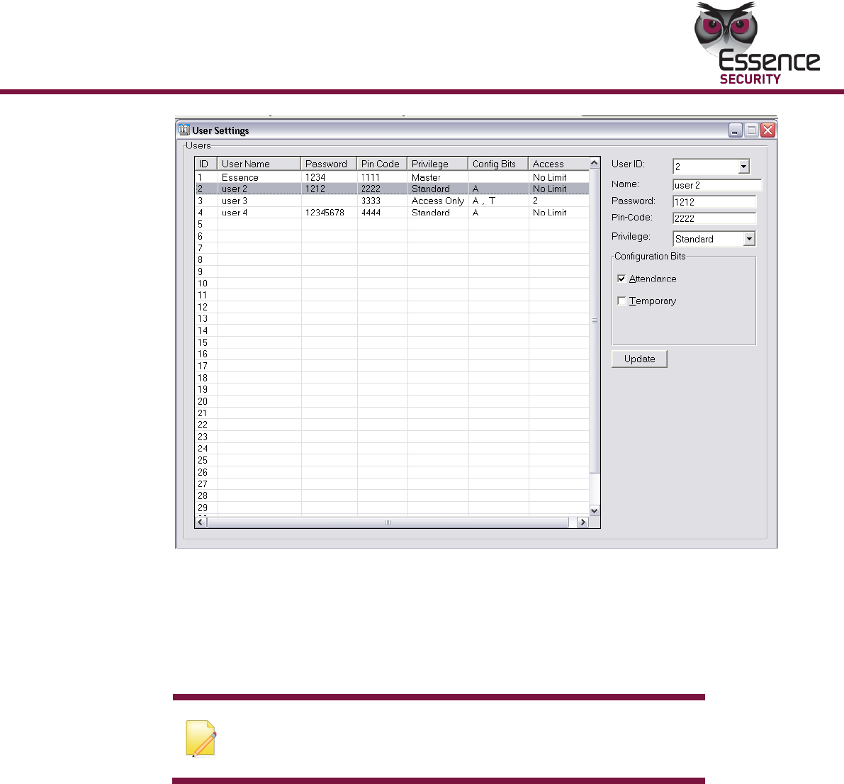
To configure the User Settings parameters:
Using the User Settings Screen, you can configure the parameters of up to 31
Users. User can be set to one of three types, Master, Standard, or Access Only,
according to their Privilege status on the premises. Their Entry/Exit attendance
can be tracked.
1. On the MAIN tab, click Users. The User Settings screen appears.
Operation
EverGuard Control Panel
63
Figure 30: User Settings Screen
2. Under Users, select a line item or from the User ID dropdown list, select the
user ID (the range is between 1 and 32).
3. For Name, enter a user name (up to 12 characters) (optional).
4. For Password, enter a password (up to 8 characters). This is for the end
user to use when accessing different settings (e.g., comfort message, etc.).
Note: The password must have 8 characters, which can be
numbers, letters and symbols. The password is used for
verification data.
5. For Pin Code, enter a 4 digit code to be used when entering and exiting.
6. From the Privilege dropdown list, select the following for access privileges:
Master – for Owners or Managers
Standard – for permanent residents or staff
Access Only – usually assigned to minor or temporary staff or visitors
7. For Configuration Bits, the following checkboxes/dropdown lists are
available: Attendance, Temporary, and No. of Accesses.
If Master is selected, Attendance is active (and is optional) and
Temporary is disabled
If Standard is selected, both Attendance and Temporary are active and
are optional
If Access Only is selected, both Attendance and Temporary are active and
mandatory
Operation
64
EverGuard Control Panel
For Temporary, from the No. of Accesses dropdown list, assign the
maximum number of times the user may access the premises. The range is 1
to 255.
8. Click Update. The User data is refreshed and displayed accordingly.
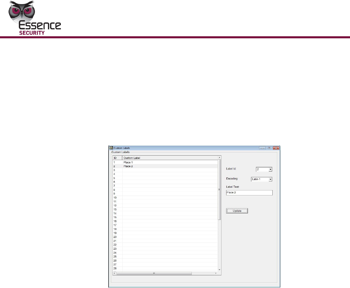
To configure the Customer Labels parameters:
The technician installing the system can define selected areas to be armed
designating these areas as zones. The technician can define up to fifty (50)
custom zones from a predefined list.
Select the Custom Labels screen.
Figure 31: Custom Labels Screen
1. Click the selected Label ID on the main screen.
2. Type the predefined text in the Label Text field.
3. Click Update.
4. The main screen displays the label.

Operation
EverGuard Control Panel
65
To edit a Custom Label:
1. Select the Label ID on the main screen.
2. Edit the free text in the label field.
3. Click Update.
To delete a Custom Label:
1. Select the Label ID on the main screen.
2. Delete the label text.
3. Click Update.
Maintenance
66
EverGuard Control Panel
4 Maintenance
A singe Maintenance LED indicates the system status when the ES7000EG control
panel is set to Maintenance mode. When the communications mini USB connecter
is attached or detached, an audible beep is sounded.
Table 19: Maintenance Related Indicators
Attach Indication/
During Installation
Yellow - open
zone
Yellow- call
guard
Attach
beep
After attachment,
connection is
identified
Fault Attached State
Yellow
Bad beep
After plug-in fail
End Install Performed
Yellow
After successful
installation
Detached Without
Preceding “End
Install”
Off
Detached
beep
After Detach, without
performing “end
install”
Detached After
Preceding “End
Install”
Off
“End install”
preceding time-out
Note: Battery maintenance - As all rechargeable batteries have a limited
lifetime (usually a few years), the battery of this product should be
replaced as recommended by its manufacturer.

FCC Radio frequency interference statement
EverGuard Control Panel
67
5 FCC Radio frequency interference
statement
This equipment has been tested and found to comply with the limits for a Class B
digital device, pursuant to part 15 of the FCC Rules. These limits are designed to
provide reasonable protection against harmful interference in a residential installation.
This equipment generates uses and can radiate radio frequency energy and, if not
installed and used in accordance with the instructions, may cause harmful interference
to radio communications. However, there is no guarantee that interference will not
occur in a particular installation. If this equipment does cause harmful interference to
radio or television reception, which can be determined by turning the equipment off
and on, the user is encouraged to try to correct the interference by one or more of the
following measures:
Reorient or relocate the receiving antenna.
Increase the separation between the equipment and receiver.
Connect the equipment into an outlet on a circuit different from that to which
the receiver is connected.
Consult the dealer or an experienced radio/TV technician for help.
Essence Security is not responsible for any radio or communication interference caused
by using other than specified or recommended cables and battery or by unauthorized
changes or modifications to this equipment.
Changes or modifications to this equipment not expressly approved by the party
responsible for compliance (Essence Security International Ltd.) could void the user’s
authority to operate the equipment.
This device complies with part 15 of the FCC Rules. Operation is subject to the
following two conditions:
1. This device may not cause harmful interference, and
2. This device must accept any interference received, including interference that
may cause undesired operation.

Specifications
68
EverGuard Control Panel
6 Specifications
Electrical
Power Supply:
Advanced switching power supply.
Input: 100~240 VAC, 50/60 Hz internal AC to DC
adaptor.
Lithium Polymer rechargeable backup battery
Battery Life:
Provides at least 60 hours backup power during
temporary loss of power source
Backup battery spec:
Lithium Polymer battery
Rated average voltage: 3.7V
Maximum capacity: 6Ah
Maximum time to recharge to 80%: 10 hours
Low-battery threshold: 3.6V
Battery Power Test:
Upon power-up and periodically
Average current
consumption during
alarm condition:
320 mA
Average current
consumption not
during alarm condition:
237 mA
90 mA when operating on backup battery
Wireless
Bi-directional:
End-to-End Bi-Directional ESI protocol
Advanced radio supervision algorithm
Modulation &
Frequency:
FM 868.3 MHz in Europe and FM 916.5MHz in America
(Factory configured)
RF Coverage:
Up to 700m (2296 feet) (Open Air Nominal)
Supervised Wireless
Devices (Powered by
Dynamic Memory Map
technology):
64 Wireless Detectors
16 RF Input Devices
16 RF Output Devices
8 Key Fobs
5 Key pads
3 tag readers
4 sirens

Specifications
EverGuard Control Panel
69
Communication
Modules:
Cellular network: GSM/GPRS Module
Quad band (850/900/1800/1900 MHz)
Transmission time:
The time measured from transmission by a wireless
detector to the time the system is requesting connection
from the cellular network.
SMS: 0.2 ±0.05 Sec
GPRS: 1 ±0.3 Sec
GSM data: 5.5 ± 1 Sec
Note that SMS message usually have much larger delays
over the cellular network than the other 2 link types.
GSM data delay could be reduced (preconfigured) on
certain cellular networks.
Functional
Bi-directional :
Instant system status feedback
Instant command Acknowledgement
Security Functionality:
5 Scenarios
32 Users
Silent SOS
Silent Duress Alarm
Internal Siren, up to 100dbA @1m (configurable)
Tamper detector (Top, Wall)
Extended Event Log with Time/Date stamp
Home Automation:
Wireless control of electrical appliances
Remote Interactivity:
Remote software upgrades
Remote programming and configuration
Long range digital
voice verification:
High quality
Two-way digital audio
Enhanced echo cancelling DSP-based algorithm
Speaker programmable gain
Safety functionality:
Separate safety alarm, up to 100dBA @1m (configurable)
Various detectors (water, gas, smoke etc.)
Various panic (SOS) devices
Environmental
Operating
Temperatures:
0°~50° Celsius (32° - 122° Fahrenheit)

Specifications
70
EverGuard Control Panel
Storage Temperatures:
-20°~60° Celsius (-4° - 140° Fahrenheit)
Humidity:
85% relative humidity, non-condensing
Physical
Dimensions:
(L x W x D)
250mm x 185mm x 50mm (9.84” x 7.28” x 1.97”)
Weight:
1180 grams (incl. battery) – unit only
Color:
Glossy White
Mounting:
Wall, with bracket
Compliance with Standards
Certification Body:
Telefication B.V.
CE:
CE mark, EMC/EMI according to ETSI EN 301 489-4
ETSI EN 301 489-1, EN 50130-4:1996
EU Directive 1999/5/EC for R&TTE
Radio:
ETSI EN 300 220-3, ETSI EN 300 220-1
CEPT/ERC Recommendation 70-03
EN 50131-5-3:2005 + A1:2008
Safety:
EN/IEC 60950-1, TUV: UL 60950-1, NOM
Security and Alarm
Systems:
EN 50131-1:2006 + A1:2009 Class-II Grade-2
EN 50131-3:2009 Class-II Grade-2
EN 50131-6:2008 Type-A
EN 50136-1-1:1998 + A1:2001 + A2:2008 (GSM/GPRS
module classification: D2, M2, T3, S1, I2, A2 ATS 4)
UL 1023:11-Jan-2010
ANSI/SIA CP-01-2010
Environmental
Regulation:
RoHS 2002/95/EC
Reliability (Mechanical
and Environmental
conditions):
EN 50130-5:1999
IEC 60068
Manufacturing and
Materials Standards:
ISO 9001:2008
ISO 14000
ANSI/IPC-610 Class II

Specifications
EverGuard Control Panel
71
Markings: