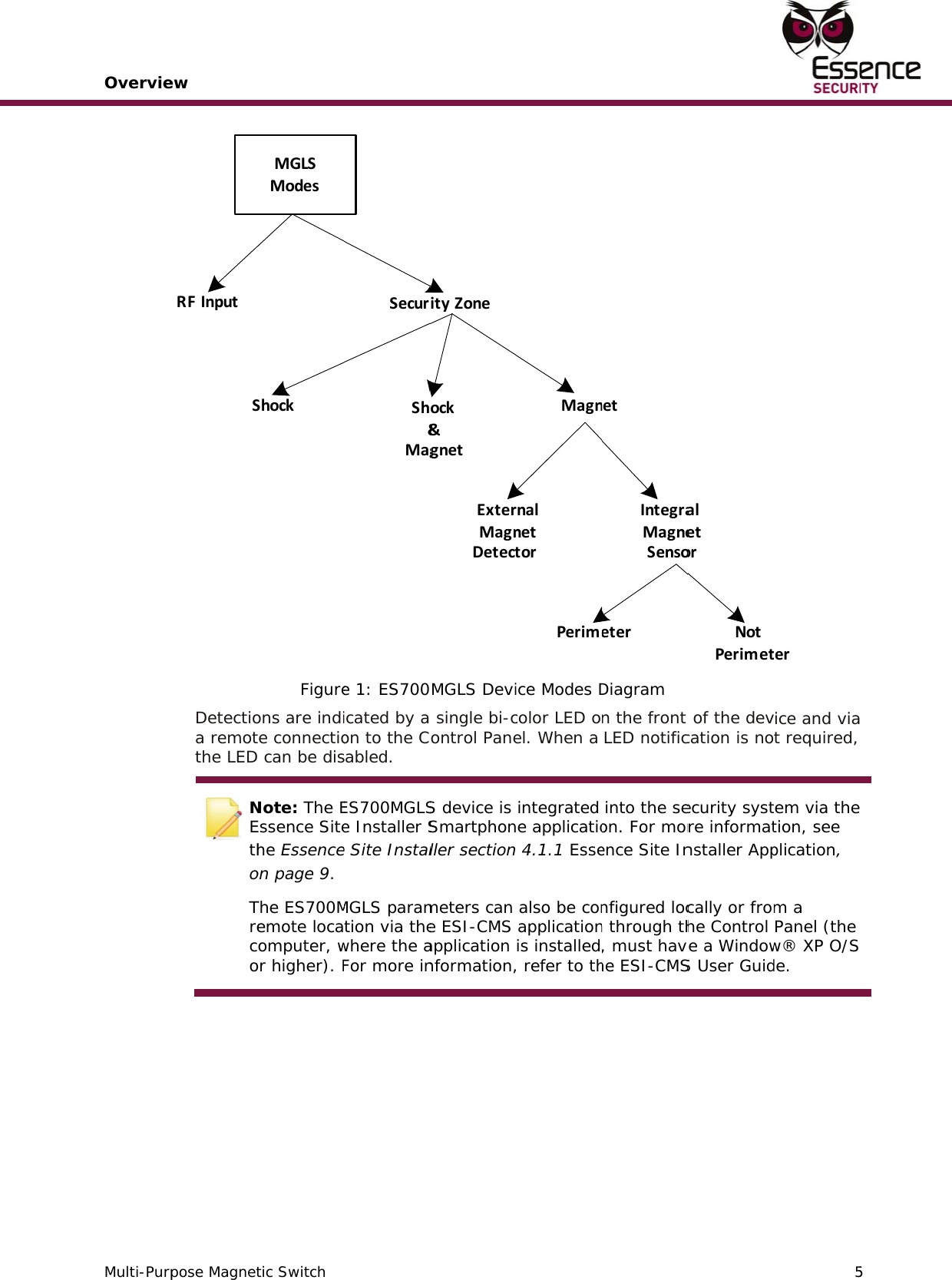
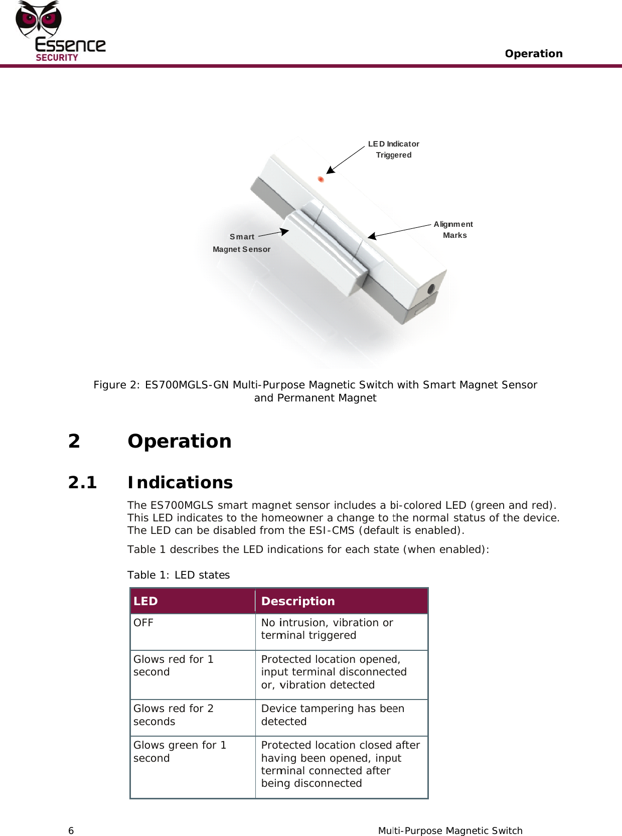
Essence Security ES700MGLS Magnet switch detector User Manual User guide
Essence Security International ltd. Magnet switch detector User guide
UserManual.wiki
>
Essence Security
>
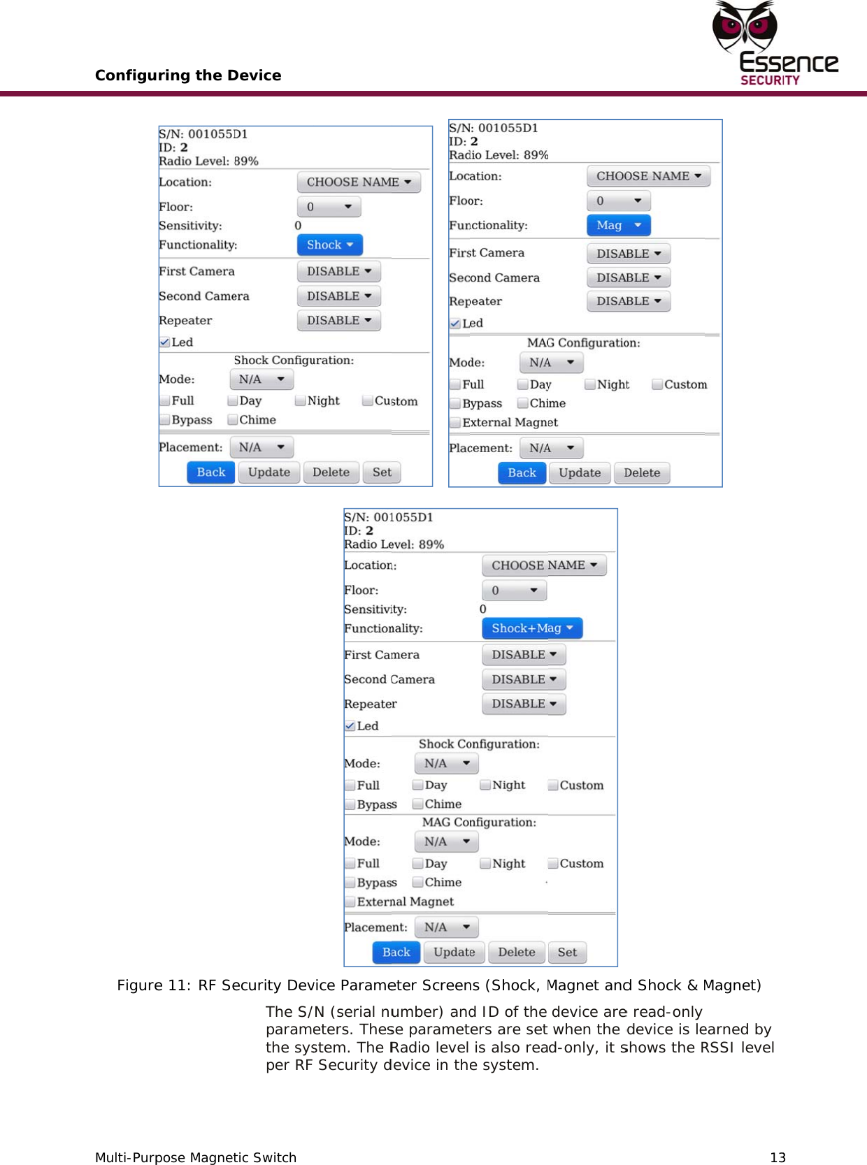
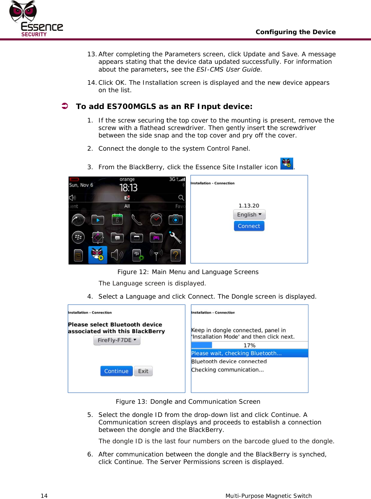
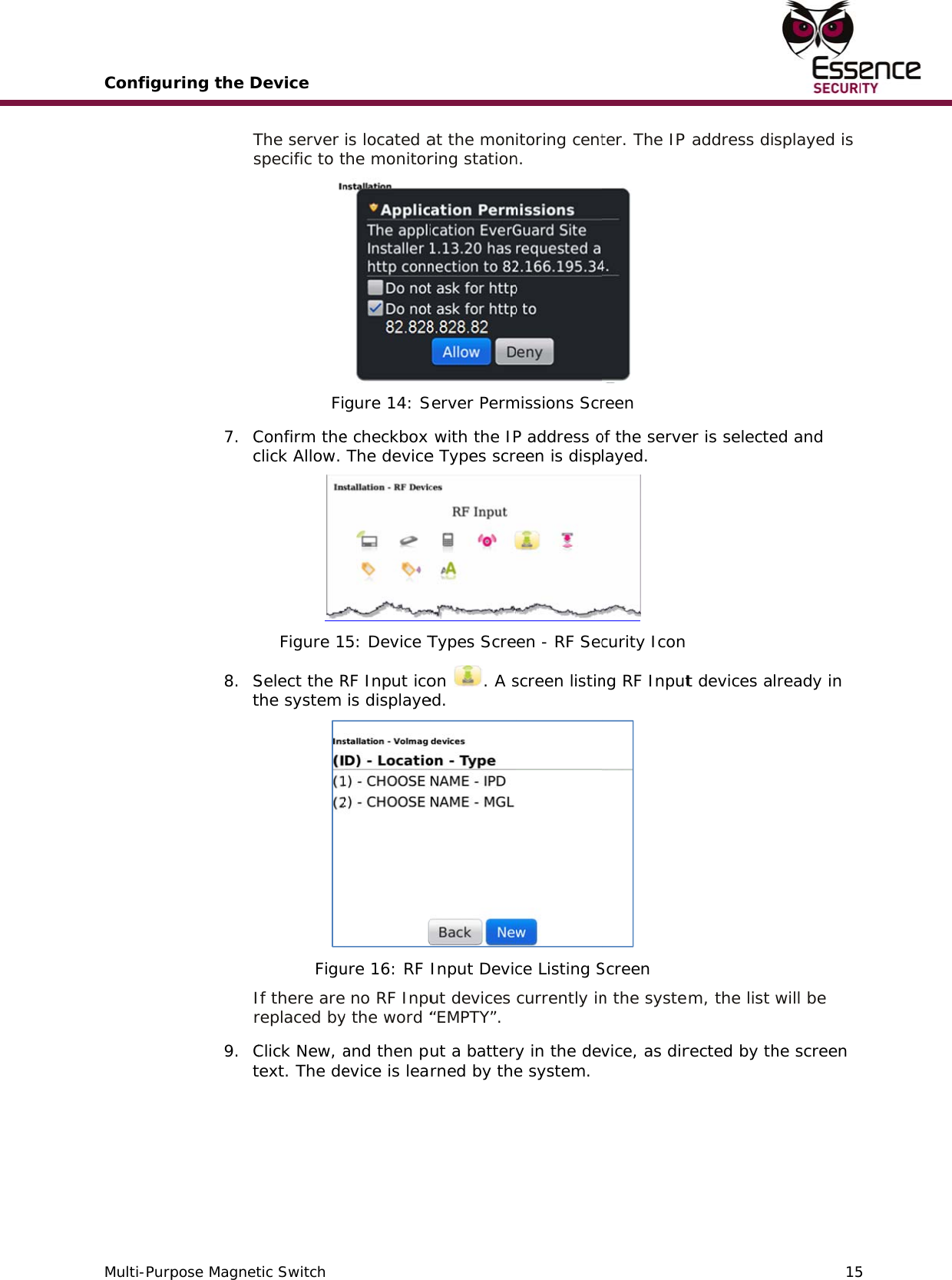
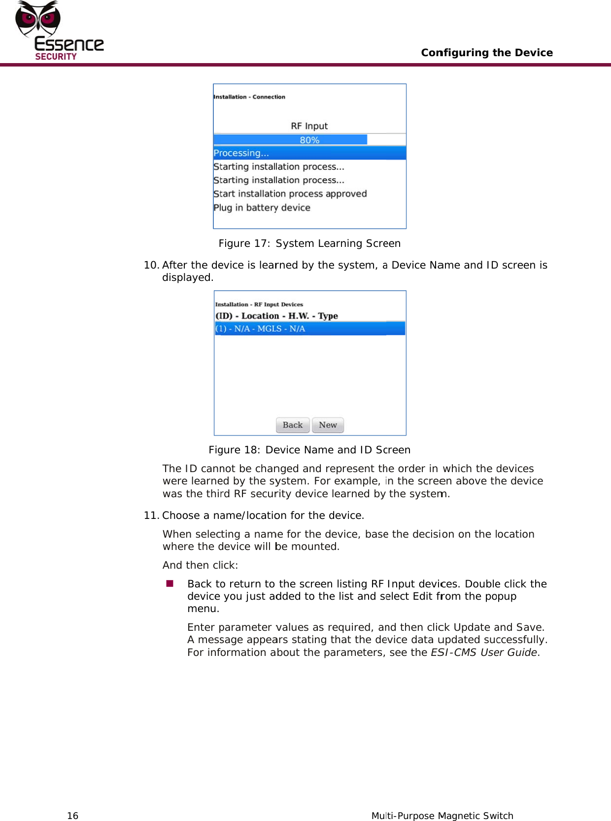
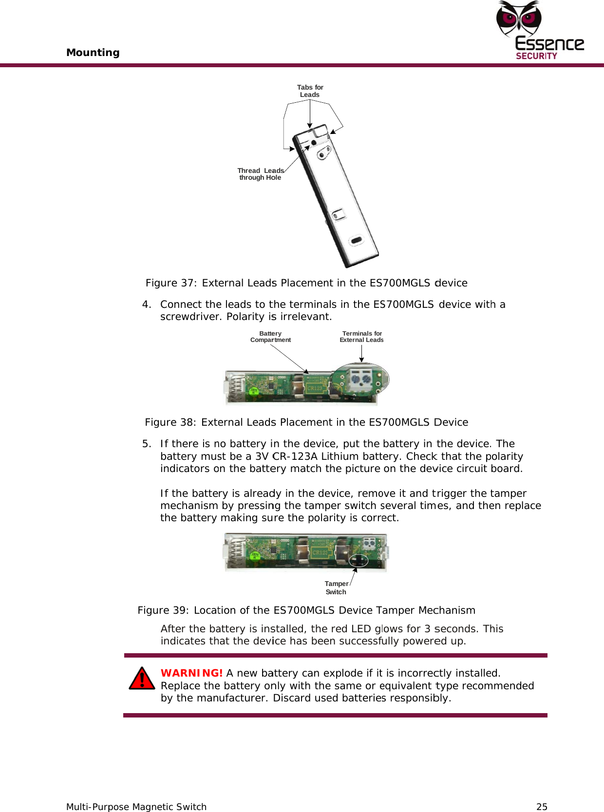
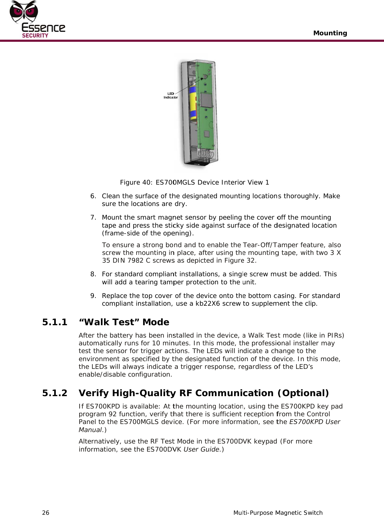
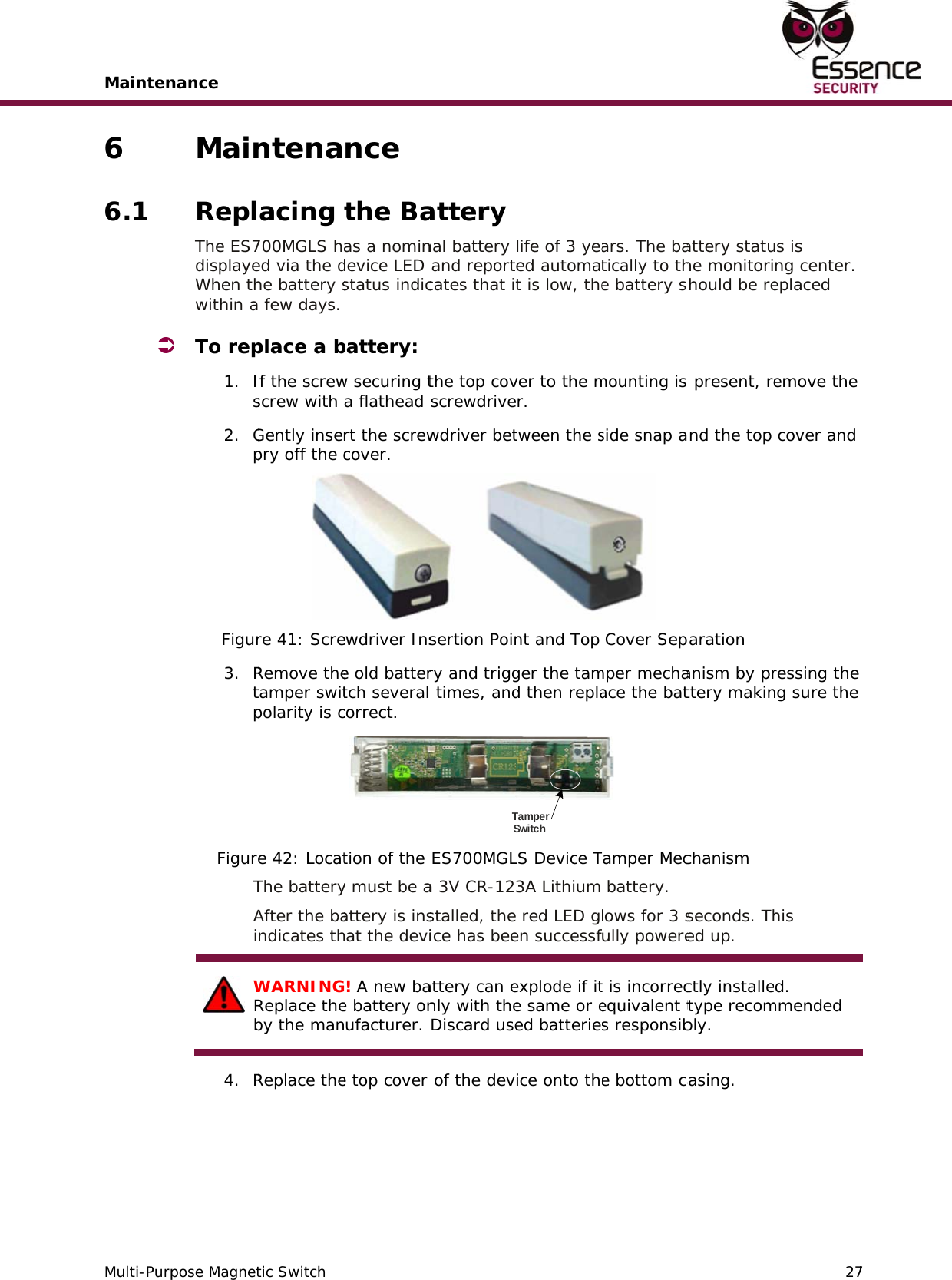
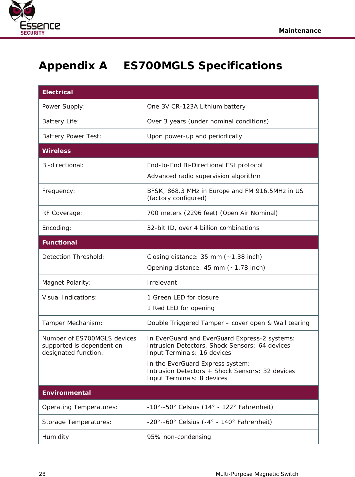
ES700MGLS User Manual
User_guide
Navigation menu
Upload a User Manual
Namespaces
Wiki Guide
HTML
PDF
Info
Views
User Manual
Discussion / Help
Navigation