Essence Security ES700MGLS Magnet switch detector User Manual User guide
Essence Security International ltd. Magnet switch detector User guide
User_guide

Mul
t
Ma
g
Use
r
ES70
0
Versi
o
May
2
t
i‐P
u
g
neti
r
Gu
i
0
MGL
S
o
n1.0
_
2
012
Par
t
u
rpo
s
cS
w
i
de
S
‐GN
_
06
t
oftheE
s
s
e
w
itch
s
sence
G
G
roup

© 2012
All right
s
This doc
Any cop
y
the prio
r
The info
r
For mor
e
Essence
12 Sder
o
Ackerst
e
Herzliya
46120 I
s
www.es
s
Tel:
Fax:
NOTE: T
part 15 of
a residenti
and used i
there is n
o
harmful in
t
the user is
-Reorient
o
-Increase
t
-Connect t
-Consult t
h
Changes o
Security L
t
Essence S
e
s
reserved.
ument is t
h
y
ing, repri
n
r
written p
e
r
mation in
c
e
informati
o
Security
o
t Abba Eb
a
e
in Towers
Pituach
s
rael
s
ence-grp.
c
+972-73
+972-9-
7
his equipmen
the FCC Rule
s
al installation
n accordance
o
guarantee t
h
t
erference to
encouraged
t
o
r relocate th
e
t
he separatio
n
he equipmen
t
h
e dealer or a
r modificatio
n
t
d.) could voi
d
e
curity Int
e
h
e protecte
n
ting, reus
e
e
rmission o
c
luded in t
h
o
n, please
a
n Street
Bldg. D
c
om
-2447777
7
729962
t has been te
s
s
. These limit
s
. This equip
m
with the inst
r
h
at interferen
c
radio or telev
t
o try to corr
e
e
receiving a
n
n
between th
e
t
into an outl
e
n experience
d
n
s to this equi
d
the user’s a
u
T
his devi
c
Operatio
n
(1) This
d
(2) This
d
interfere
n
e
rnational
L
d intellect
u
e
, reprodu
c
f Essence
S
h
is docume
n
contact:
s
ted and foun
s
are designe
d
ent generate
s
r
uctions, may
c
e will not oc
c
ision receptio
e
ct the interfe
n
tenna.
e
equipment
a
e
t on a circuit
d
radio/TV te
c
pment not ex
u
thority to op
c
e complies
w
n
is subject t
o
d
evice may n
o
d
evice must a
n
ce that may
L
td.
u
al propert
y
c
tion
,
adap
t
S
ecurity Lt
d
n
t is subje
c
n
d to comply
w
d
to provide r
s
, uses and c
a
cause harmf
u
c
ur in a partic
u
n, which can
rence by one
a
nd receiver.
different fro
m
c
hnician for h
e
pressly appr
o
erate the eq
u
w
ith Part 15 o
f
o
the followin
g
o
t cause har
m
ccept any int
e
cause undesi
r
y
of the Es
s
t
ation distri
d
is prohibi
t
c
t to chang
w
ith the limit
s
easonable pr
o
a
n radiate rad
u
l interferenc
e
u
lar installati
o
be determine
d
or more of t
h
m
that to whic
e
lp.
o
ved by the p
a
ipment.
f
the FCC Rul
e
g
two conditio
m
ful interferen
e
rference rec
e
r
ed operation
.
s
ence Secu
bution or t
r
t
ed.
e without
n
for a Class B
o
tection again
io frequency
e
e
to radio co
m
o
n. If this equ
d
by turning
t
e following m
h the receive
r
a
rty responsi
b
e
s.
n
s:
ce, and
e
ived, includi
n
.
rity Intern
a
ranslation
w
n
otice.
B
digital devic
e
n
st harmful in
t
e
nergy and, i
f
m
munications.
u
ipment does
c
t
he equipmen
t
m
easures:
r
is connecte
d
b
le for compli
a
n
g
a
tional Ltd.
w
ithout
e
, pursuant t
o
t
erference in
f
not installed
However,
c
ause
t
off and on,
d
.
a
nce (Essenc
e
o
e

Table o
f
Multi-Pur
p
Tab
1O
v
2O
p
2.
1
3In
3.
1
3.
2
3.
3
4C
o
4.
1
5M
o
5.
1
6M
a
6.
1
Appen
d
f
Content
s
p
ose Magne
t
le of
C
v
erview .
.
p
eration
.
1
Indicati
o
stallatio
n
1
Installa
t
2
Power ..
3
Selectin
o
nfigurin
g
1
Setting
s
4.1.1
o
unting .
.
1
Installi
n
5.1.1
5.1.2
a
intenan
c
1
Replaci
n
d
ix A
s
t
ic Switch
C
ont
e
.
.............
.
.
.............
.
o
ns ..........
n
Overvi
e
t
ion Work
F
...............
g a Mounti
g
the De
v
s
and Defa
u
Essence S
.
.............
.
n
g the ES7
0
“Walk Tes
t
Verify Hig
h
c
e ..........
.
n
g the Batt
e
ES700M
G
e
nts
.
.............
.
.............
..............
.
e
w ..........
F
low .........
.
..............
.
ng Locatio
n
v
ice ........
u
lts ..........
.
ite Installe
.
.............
0
0MGLS D
e
t
” Mode ...
.
h
-Quality
R
.
.............
e
ry ..........
.
G
LS Spe
c
.............
.
.............
.
.
..............
.............
.
.
..............
.
..............
n
.............
.............
.
.
..............
r Applicati
o
.............
.
e
vice (as S
h
.
..............
R
F Commu
n
.............
.
.
..............
c
ification
s
.
.............
.
.............
...............
.
.............
...............
...............
...............
.
.............
...............
o
n ............
.
.............
h
ock Senso
...............
n
ication (O
p
.
.............
...............
s
............
.............
.
.............
.
..............
.
.............
.
..............
.
..............
.
..............
.
.............
.
..............
.
..............
.
.............
.
r and/or M
a
..............
.
p
tional) ....
.
.............
.
..............
.
.............
.
.
.............
.
.............
.
..............
.
.............
.
..............
.
..............
.
..............
.
.............
.
..............
.
..............
.
.............
agnet Det
e
.
..............
.
..............
.
.............
.
..............
.
.............
3
.......... 4
.......... 6
........... 6
.......... 7
........... 7
........... 8
........... 8
.......... 8
........... 8
........... 9
........ 21
e
ctor) .. 21
.......... 26
.......... 26
........ 27
.......... 27
........ 28
3

4
1
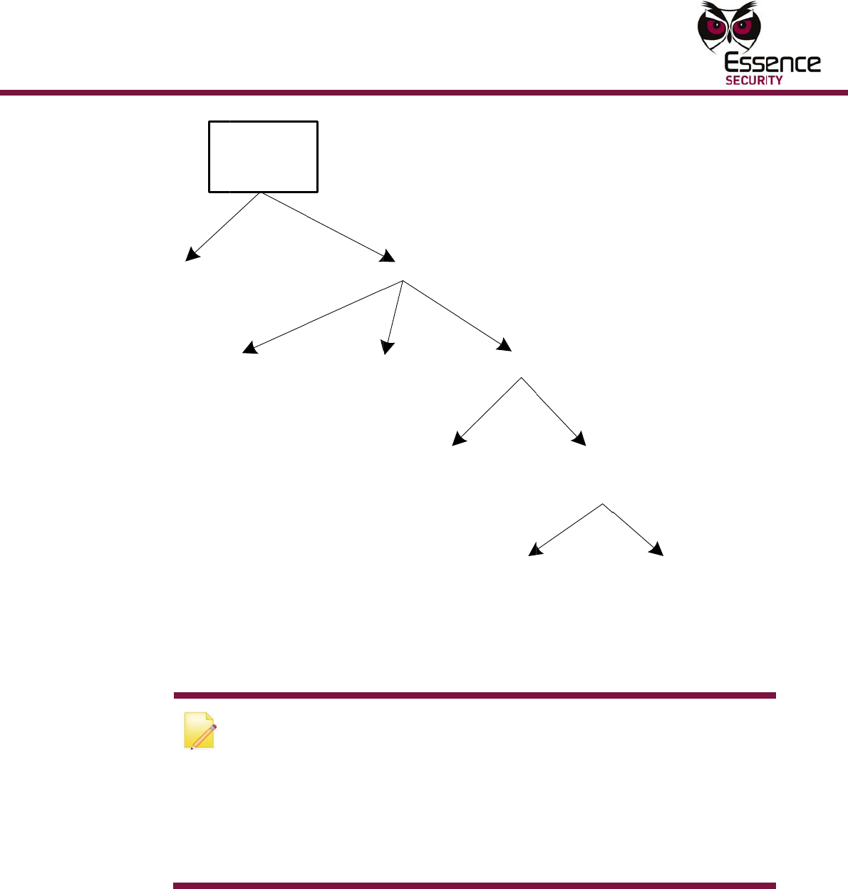
Ove
The ES
7
operate
d
compos
e
smart
m
RF com
m
operate
d
mounts
smart
m
Control
The ES
7
modes:
De
t
int
e
De
t
De
t
se
n
As
de
v
de
v
rvie
w
7
00MGLS
M
d
magnet
s
e
d of two
p
m
agnet sen
s
m
unication
d
. When t
h
next to th
e
m
agnet sen
s
Panel.
7
00MGLS d
t
ects intru
s
e
gral mag
n
t
ects intru
s
t
ects surfa
c
n
sor is mo
u
a pure RF
v
ice. Possi
b
v
ice are as
Gas Detec
t
Flood Dete
Fire Detec
t
Panic (SO
S
Gas Monit
o
w
M
ulti-Purpo
s
s
witch dete
p
arts: a sm
s
or is the
b
with the
C
e magnet
d
e
smart m
a
s
or change
e
vice has
a
s
ions at br
e
n
et sensor.
s
ions by co
c
e shocks
/v
u
nted.
input devi
c
b
le externa
follows:
t
or
ctor
t
or
S
) Button
o
r
s
e Magneti
c
e
ctor
/
shock
art magne
t
b
rain of the
C
ontrol Pan
e
d
etector is
a
gnet sens
o
s, the sma
a
multipur
p
e
ak-in poin
t
nnecting t
o
v
ibrations
o
c
e, detects
l devices t
h
Mu
l
c
Switch is
detector/
R
t
sensor a
n
device; it
e
l. The sm
a
operation
a
o
r. When t
h
rt magnet
s
ose design
t
s such as
d
o
an extern
o
n the surf
a
status cha
n
h
at may be
ti-Purpose
M
a bi-directi
R
F input te
r
d a perma
n
is responsi
a
rt magnet
l, the per
m
h
e magnet’
s
s
ensor trig
g
that supp
o
d
oors and
w
al wired m
a
a
ce where
t
n
ges in a
w
connected
M
agnetic S
w
i
onal RF, b
a
r
minal. It i
s
nent magn
ble for det
e
sensor is
b
m
anent ma
g
s proximit
y
g
ers an ac
t
o
rts the fol
w
indows t
h
agnet sen
s
the smart
m
w
ired exter
n
d
to the ES
7
Overvie
w
itch
a
ttery
s
et. The
e
ction and
b
attery
g
net
y
to the
t
ion via th
e
l
owing
h
rough an
or.
m
agnet
n
al input
7
00MGLS
w
e
Overvi
e
Multi-Pur
p
e
w
p
ose Magne
t
RFInput
S
Detecti
o
a remot
the LED
N
E
t
h
o
T
r
e
c
o
t
ic Switch
MGLS
Modes
S
hock
Figur
e
o
ns are ind
i
e connecti
o
can be di
s
N
ote: The
E
E
ssence Sit
e
h
e Essenc
e
o
n page
9.
T
he ES700
M
e
mote loca
omputer,
w
o
r higher).
F
Secur
Sh
&
Ma
g
e
1: ES700
i
cated by a
o
n to the C
s
abled.
E
S700MGL
S
e
Installer
S
e
Site Insta
l
M
GLS para
m
tion via th
e
w
here the
a
F
or more i
n
ityZone
oc
k
&
gne
t
Exte
r
Mag
n
Detec
t
MGLS Dev
i
single bi-
c
ontrol Pan
e
S
device is
S
martphon
l
le
r
section
m
eters can
e
ESI-CMS
a
pplication
n
formation
,
Perim
e
Mag
n
r
nal
n
et
t
or
i
ce Modes
D
c
olor LED o
e
l. When a
integrated
e applicati
o
4.1.1 Ess
e
also be co
n
applicatio
n
is installed
,
refer to t
h
e
ter
n
et
Integr
a
Magn
e
Sens
o
D
iagram
n
the front
LED notifi
c
into the s
e
o
n. For mo
r
e
nce Site I
n
n
figured lo
c
n
through t
h
,
must hav
e
h
e ESI-CM
S
al
e
t
o
r
Not
Perime
t
of the dev
c
ation is no
e
curity sys
t
re informa
t
n
staller Ap
p
c
ally or fro
m
h
e Control
e a Windo
w
S
User Gui
d
5
er
ice and via
t required,
t
em via the
t
ion, see
p
lication,
m
a
Panel (the
w
® XP O/S
d
e.
5
6
Fig
u
2
2.1
u
re 2: ES7
0
Ope
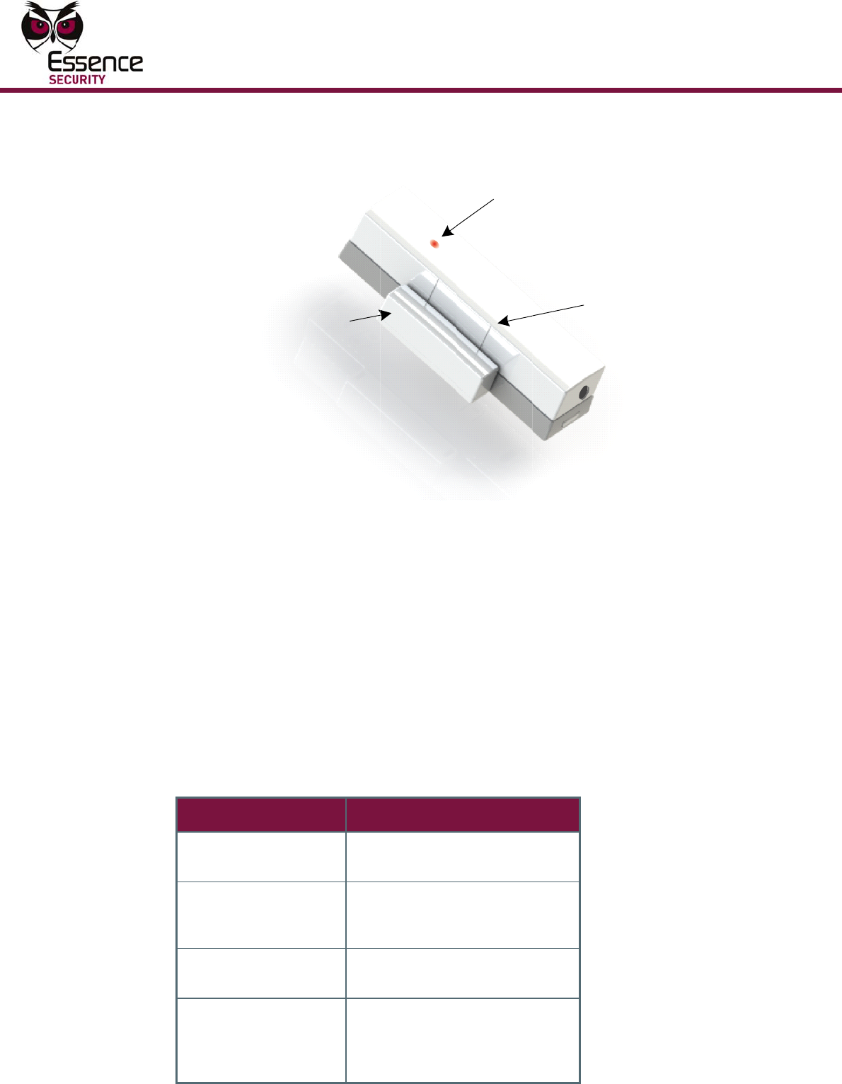
Indi
c
The ES
7
This LE
D
The LE
D
Table 1
Table 1
:
LED
OFF
Glows
secon
d
Glows
secon
d
Glows
secon
d
Ma
g
0
0MGLS-G
N
ratio
n
c
ation
s
7
00MGLS s
m
D
indicates
D
can be di
s
describes
t
:
LED state
red for 1
d
red for 2
d
s
green for
1
d
Smart
g
net Sensor
N
Multi-Pur
and
P
n
s
m
art magn
to the ho
m
s
abled fro
m
t
he LED in
d
s
De
s
No
i
ter
m
Pro
t
inp
u
or,
v
De
v
det
e
1
Pro
t
hav
ter
m
bei
n
pose Magn
P
ermanent
et sensor i
m
eowner a
m
the ESI-
C
d
ications fo
s
cription
i
ntrusion,
v
m
inal trigg
e
t
ected loca
t
u
t terminal
v
ibration d
e
v
ice tampe
r
e
cted
t
ected loca
t
ing been o
p
m
inal conn
e
n
g disconn
e
Mu
l
LED In
Trig
g
etic Switch
Magnet
ncludes a
b
change to
t
C
MS (defau
r each sta
t
v
ibration o
r
e
red
t
ion opene
d
disconnec
t
e
tected
r
ing has be
e
t
ion closed
p
ened, inp
u
e
cted after
e
cted
ti-Purpose
M
d
icator
g
ere
d
A
lig
n
M
with Sma
r
b
i-colored
L
t
he normal
l
t is enable
e (when e
n
d
,
t
ed
e
n
after
u
t
O
M
agnetic S
w
n
ment
M
arks
r
t Magnet
S
L
ED (green
status of
t
e
d).
n
abled):
O
peratio
n
itch
S
ensor
and red).
t
he device.
n
Install
a
Multi-Pur
p
3
3.1
a
tion Over
v
p
ose Magne
t
Device
t
signals
t
configu
r
the stat
For mo
r
Default
s
Actions
Ma
m
o
Sh
o
wh
In
p
th
e
te
r
De
v
Ins
t
The ES
7
the feat
The con
Sh
o
Sh
o
In
t
In
p
N
g
t
e
Inst
a
Perform
1.
H
2.
F
3.
D
o
4.
D
5.
I
(
c
r
v
iew
t
ic Switch
t
rigger beh
t
o the Con
t
r
able from
t
us of the s
y
r
e informat
i
s
, on page
8
that trigge
gnet Dete
c
o
ved away
o
o
ck Senso
r
ere the de
v
p
ut Termin
a
e
ES700MG
r
minals ma
y
v
ice Maint
e
t
allati
o
7
00MGLS d
ure(s) tha
t
figurations
o
ck Senso
r
o
ck Senso
r
t
rusion Det
e
p
ut Termin
a
N
ote: If th
e
o-between
e
rminal), t
h
a
llatio
the install
H
ave the t
o
F
amiliarize
D
etermine
t
o
r a combi
n
D
ecide wh
e
I
nstall and
(
BlackBerr
y
c
onfigurati
o
r
efer to the
a
vior is no
t
t
rol Panel.
T
t
he softwa
r
y
stem (Ar
m
i
on on con
f
8
.
r a respon
s
c
tor: Open
o
r towards
r
: Vibration
v
ice is mo
u
a
l: Leads a
LS device.
y
also trigg
e
nance: Lo
w
o
n O
v
e
vice can
b
t
will be us
e
pertain to
r
and Intru
s
r
(exclusiv
e
e
ctor –doo
r
a
l device (
e
e
device wi
l
for the se
c
h
e perman
e
n Wor
a
tion proc
e
o
ols, batter
y
the owner
t
he functio
n
n
ation).
e
re the dev
i
c
onfigure t
y
). After th
e
o
n in collab
ESI-CMS
U
t
limited to
T
he action
r
e part of t
m
, Disarm
a
f
iguring th
e
s
e from th
e
and close
a
the smart
s (in sever
u
nted.
re disconn
e
Triggers f
r
g
er a Contr
o
w
battery
o
v
ervi
e
b
e installed
e
d on the
p
the followi
s
ion Detec
t
e
ly)
r
s & windo
w
e
xclusively
)
l
l be used
t
c
urity syst
e
e
nt magne
t
k Flo
w
e
ss in the f
o
y
and scre
w
with the a
v
nality for t
h
i
ce will be
m
t
he device
w
e
installati
o
oration wi
t
U
ser Guide
the LED o
n
taken fro
m
he installa
t
a
nd Partial
e
ES700MG
e
Control P
a
a
ction whe
r
magnet d
e
ity or quan
e
cted or re
c
r
om the ex
t
o
l Panel re
s
o
r ES700M
G
e
w
in multipl
e
p
remises.
ng functio
n
t
or operati
n
w
s (exclusi
)
t
o detect s
u
e
m and an
t
is not req
w
o
llowing lo
g
w
s (option
a
v
ailable fu
n
h
e device (
m
ounted.
w
ith the Es
o
n, perfor
m
h the mon
i
.
n
the devic
m
the Contr
o
t
ion proces
s
Arm).
LS device,
a
nel are as
r
e the per
m
e
tector.
tity) is det
e
c
onnected
t
t
ernal devi
c
s
ponse.
G
LS device
e
configura
t
n
alities:
n
g from th
e
v
ely)
u
rface shoc
external d
e
uired.
g
ical order.
a
l) availabl
e
n
ctional co
n
intruder, s
h
s
ence Site
m
a more c
o
toring cen
t
c
e, but also
ol Panel is
s
and may
see
4.1 S
e
follows:
m
anent ma
g
e
cted on t
h
to the ter
m
c
e connect
e
tampering
t
ions, dep
e
e
same dev
c
ks exclusi
v
e
vice (inpu
t
.
e
.
n
figuration
s
h
ock, inpu
t
Installer
o
mprehens
i
t
er via the
7
includes
depend on
e
ttings and
g
net is
h
e surface
m
inals in
e
d to the
.
e
nding on
ice
v
ely or as a
t
s
.
t
terminal,
ve
ESI-CMS,
7
8
3.2
3.3
4
4.1
6.
M
a
t
i
7.
T
Pow
e
The ES
7
giving a
battery.
Sele
c
The ES
7
(such a
s
followin
g
Th
e
of
a
Do
su
r
N
c
If the E
S
the foll
o
Th
e
sid
on
su
r
N
m
a
h
Con
f
Sett
i
Once th
section
able to
r
configu
r
Site Ins
t
may als
M
ount the
d
a
ppropriat
e
t
he mount
a
nformation
T
est the de
v
e
r
7
00MGLS s
m
nominal b
c
ting
a
7
00MGLS d
s
a doorpo
s
g
factors
m
e
ES700M
G
a
possible
i
not install
r
faces kno
w
N
ote: Do n
o
harged, as
S
700MGLS
o
wing addit
e
ES700M
G
e of the d
o
the surfac
e
r
face is be
s
N
ote: Thou
m
ounting t
a
lso be use
d
h
ole for the
f
iguri
i
ngs a
n
e battery i
s
4.1.1 Esse
n
r
ecognize
/
l
r
ed to fit t
h
t
aller appli
c
o be confi
g
d
evice as d
e
, use two
3
a
nd two pr
o
about the
v
ice.
m
art magn
attery life
o
a
Mou
n
e
vice can
b
s
t or windo
w
m
ust be tak
e
G
LS device
i
ntruder, b
u
the ES700
w
n to inter
f
o
t mount t
h
this may l
i
device will
ion criteria
G
LS device
o
or or wind
o
e
of the do
o
s
t to ensur
e
gh the inst
a
pe to affix
d
. The scre
w
screw is p
r
ng th
e
n
d De
f
s
inserted i
n
ce Site In
s
earn the n
e
e needs of
c
ation, as
d
g
ured via t
h
etermined
3
X 35 DIN
o
vide tam
p
screws se
e
et sensor
r
o
f 3 years.
n
ting
L
b
e mounte
d
w frame).
W
en into co
n
should be
m
u
t still acc
e
0
MGLS devi
f
ere with r
a
h
e device
o
i
mit the de
be used t
o
for selecti
o
smart ma
g
o
w openin
g
o
r or wind
o
e
optimal c
o
t
allation in
s
the devic
e
w will prov
r
ovided in
t
e
De
v
f
aults
nto the de
v
s
taller App
e
w device.
the install
a
d
escribed i
n
h
e ESI-CM
S
Mu
l
by the sel
e
7982 C sc
r
p
er/tear off
e
, Figure 3
2
r
equires on
The perm
a
L
ocati
o
d
on the fix
W
hen sele
c
n
sideration
:
m
ounted a
s
e
ssible for
o
ce on met
a
a
dio trans
m
o
n surfaces
vice’s effe
c
o
detect in
t
o
n a moun
t
g
net senso
r
g
. The per
m
o
w (where
o
ntact with
s
tructions
b
e
to a surfa
c
ided a rein
t
he mounti
v
ice
v
ice, via Si
t
lication, o
n
After the
d
a
tion and t
n
this secti
o
S
applicatio
Co
n
ti-Purpose
M
e
cted funct
i
r
ews to ad
d
protection
2
, on page
e
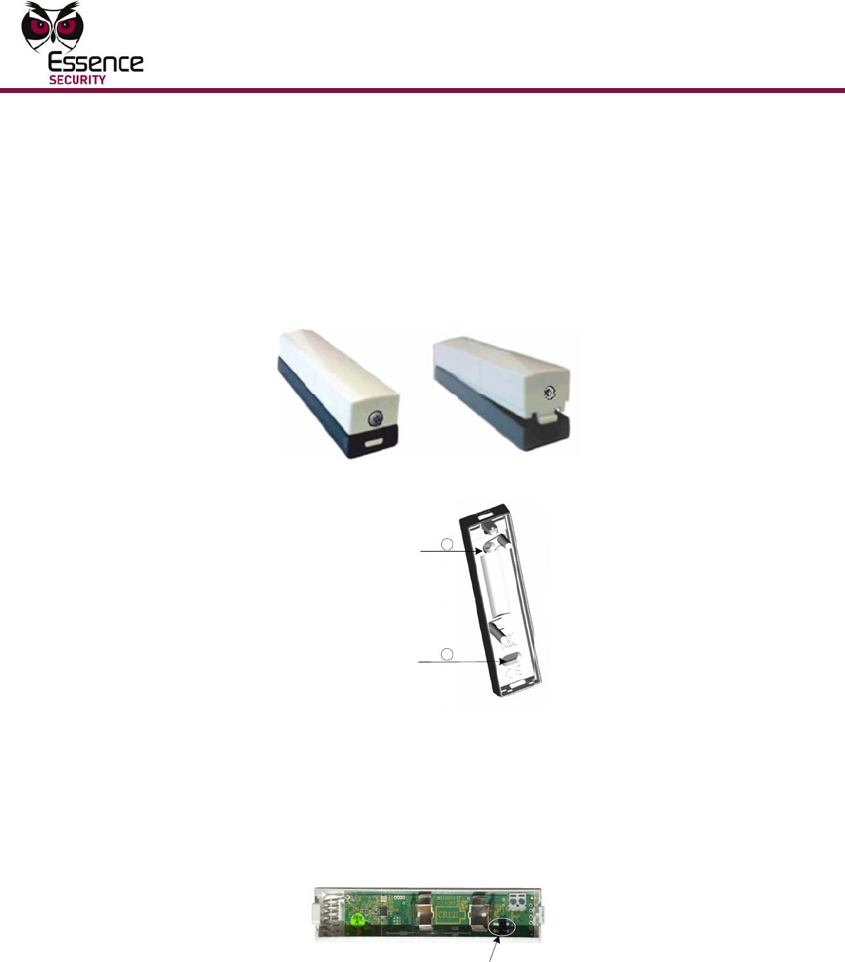
3V C
R
-1
2
a
nent mag
n
o
n
ed side of
a
c
ting a mo
u
s
high as p
o
ccasional
m
a
llic surfac
e
m
issions.
that can b
c
tiveness.
t
rusions or
t
ing locatio
should be
m
anent ma
g
r
equired).
A
the moun
t
elow speci
f
c
e, A scre
w
f
orced bon
d
ng.
t
e Installer
page 9), t
d
evice is le
a
h
e homeo
w
o
n. Additio
n
n through
t
n
figuring
t
M
agnetic S
w
ionality. W
h
d
extra su
p
. For more
22.
2
3A Lithiu
m
n
et does n
o
a
protecte
d
u
nting posi
t
ossible, ou
m
aintenan
c
e
s or on ot
h
b
e magneti
c
surface sh
o
o
n
placed on
g
net shoul
d
A
smooth
a
t
ing tape.
f
y using th
e
w
(not prov
d to the su
r
instructio
n
t
he Control
a
rned, it c
a
w
ner via th
e
nally, para
t
he Contro
l
t
he Devic
e
itch
h
ere
p
port to
m
battery,
o
t require a
d
opening
t
ion, the
t of reach
c
e.
h
er
c
ally
o
cks, use
the frame
d
be placed
a
nd clean
e
ided) may
rface. A
n
s (see
Panel is
a
n be
e
Essence
m
eters
l
Panel.
e
Configu
Multi-Pur
p
4.1.1
ring the
D
p
ose Magne
t
For mo
r
Guide.
Esse
n
The ES
7
on the
s
magnet
device
c
it into t
h
The ins
t
ES700
M
As
De
t
or
As
ico
de
v
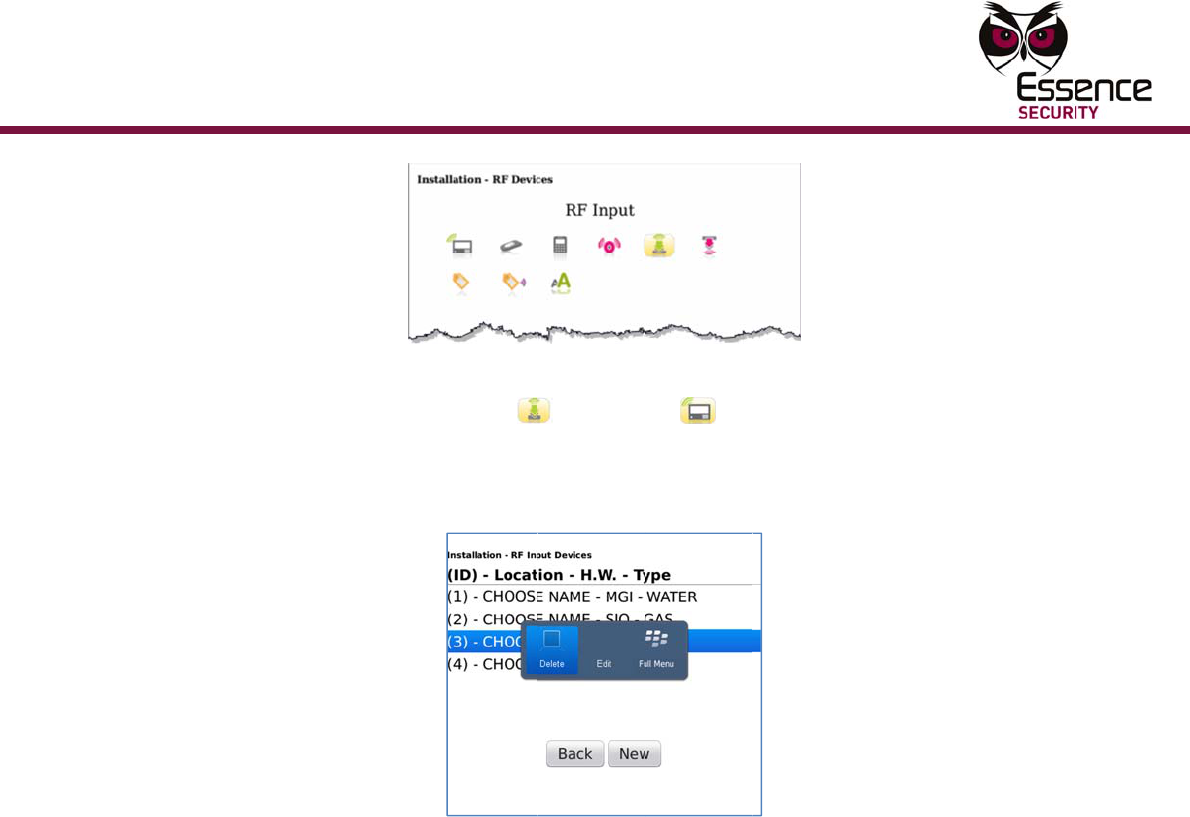
To ad
d
or, M
a
1.
I
s
b
2.
C
3.
F
T
D
evice
t
ic Switch
r
e informat
i
n
ce Sit
e
7
00MGLS d
s
urface wh
e
as in open
c
an act as
a
h
e security
t
allation pr
o
M
GLS devic
e
an RF Sec
u
t
ector): S
e
both.
an RF Inp
u
n , an
d
v
ice termin
Note:
as a li
m
ES700
and th
device
d
ES700
M
ag
net &
S
I
f the scre
w
s
crew with
b
etween th
e
C
onnect th
e
F
rom the B
l
Figu
r
T
he Langu
a
i
on about t
e
Insta
l
e
vice dete
c
e
re the de
v
ing/closing
a
n input de
system.
o
cess varie
e
being ins
t
u
rity devic
e
lect the R
F
u
t device (I
then sele
c
als.
The RF Se
c
m
ited inpu
t
MGLS devi
c
e device c
o
is a wired
M
GLS a
s
S
hock s
e
w
securing
t
a flathead
e
side sna
p
e
dongle to
l
ackBerry,
c
r
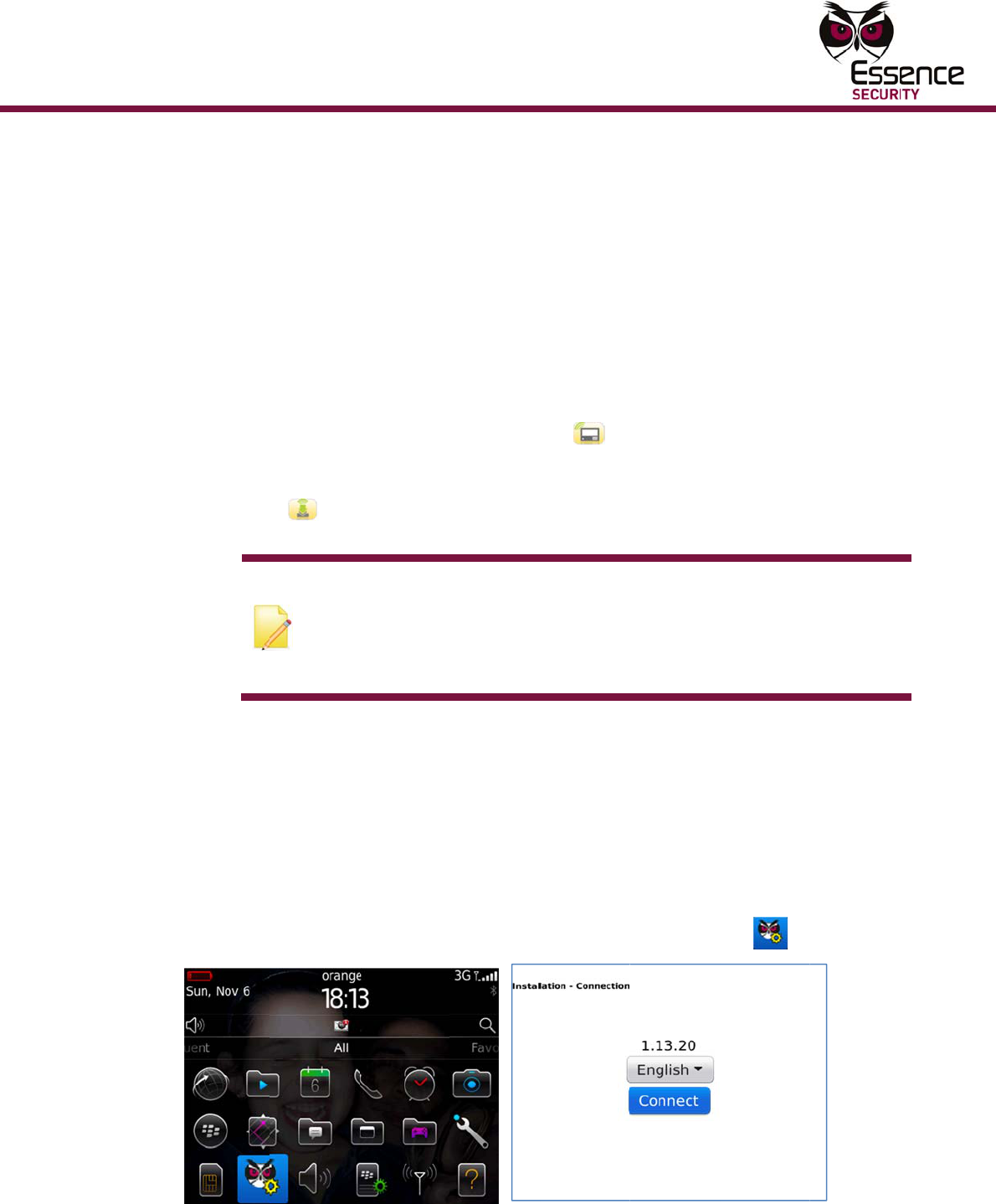
e 3: Main
M
a
ge screen
he ESI-CM
S
l
ler Ap
p
c
ts change
s
v
ice is mou
n
g
a door or
e
vice for an
s dependi
n
t
alled:
e
(Integral
F
Security i
c
I
nput Term
c
t the type
curity func
t
t
terminal.
ce is confi
g
o
nnected t
o
magnet d
e
s
an RF
S
e
nsor):
t
he top co
v
screwdrive
p
and the t
o
o
the syste
m
click the E
s
Menu and
L
is displaye
d
S
applicati
o
p
licatio
s
in shock
a
n
ted, or ch
a
window. I
n
external
w
n
g on the i
n
Magnetic
D
c
on , a
n
inal functi
o
of device
c
t
ionality d
o
This optio
n
g
ured as R
F
o
the input
e
vice.
S
ecurity
d
v
er to the
m
r. Then ge
n
o
p cover a
n
m
Control
P
s
sence Site
L
anguage
S
d
.
o
n, refer to
n
a
nd magne
t
a
nges in t
h
n
addition,
t
w
ired perip
h
n
tended pu
r
D
etector an
d
n
d then ch
o
o
nality): Se
c
onnected
t
o
es allow y
o
n
is availab
l
F
Security
M
terminal o
f
d
evice (
m
ounting is
n
tly insert
t
n
d pry off t
P
anel.
Installer i
c
S
creens
o
the ESI-C
tism, i.e.,
v
h
e vicinity
o
t
he ES700
M
h
eral and i
n
r
pose of th
d or Shoc
k
o
ose Shoc
k
e
lect the R
F
t
o the ES7
0
o
u to use t
h
le when th
e
M
agnet De
t
f
the ES70
0
Ma
g
net,
present, r
e
t
he screwd
he cover.
c
on .
9
MS User
v
ibrations
o
f a
M
GLS
n
corporate
e
k
k
, Magnet,
F
Input
0
0MGLS
h
e device
e
t
ector only
;
0
MGLS
Shock
e
move the
river
9
;
10
4.
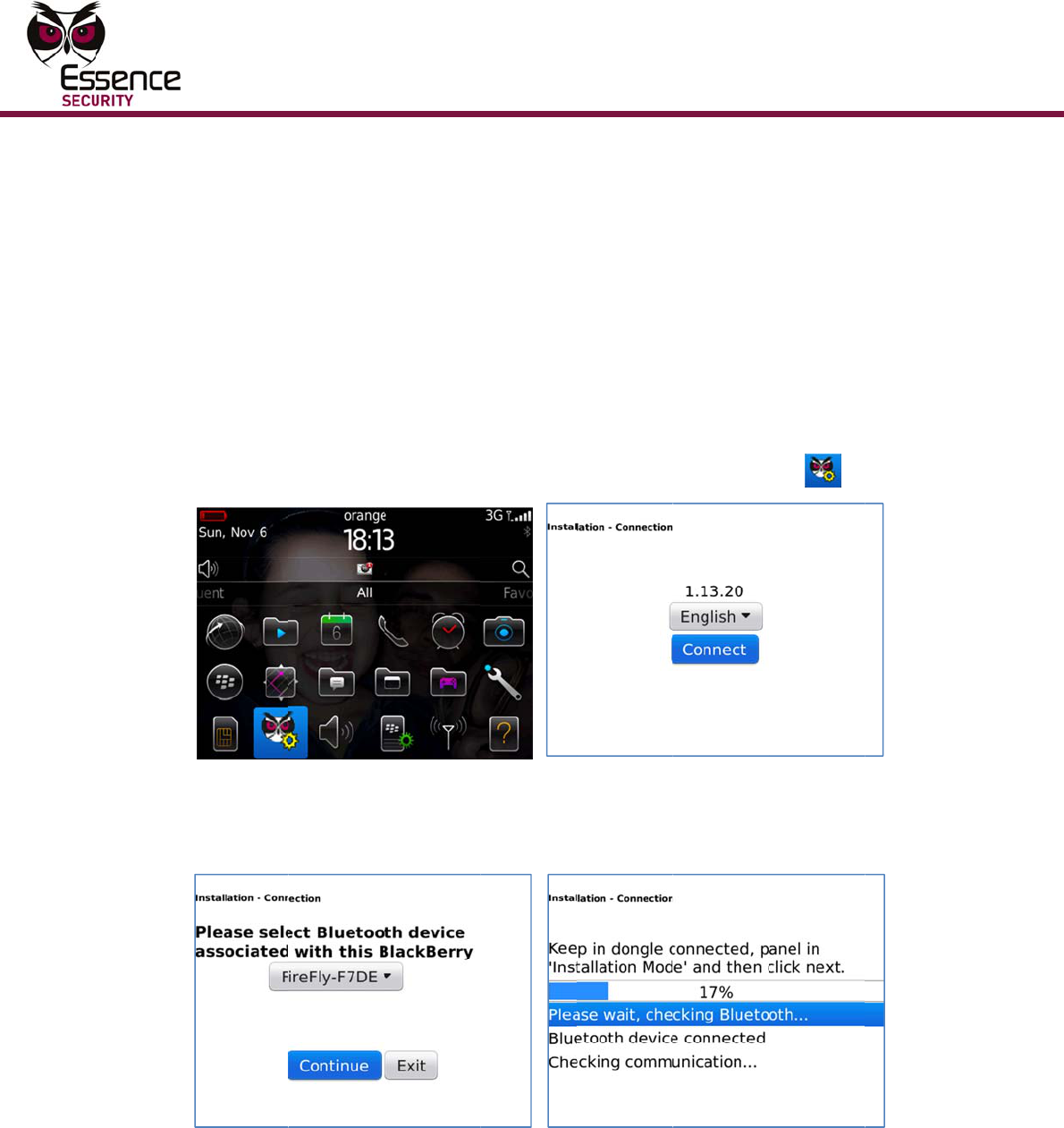
S
5.
S
C
b
T
6.
A
c
T
s
7.
C
c
8.
S
M
d
o
S
elect a La
n
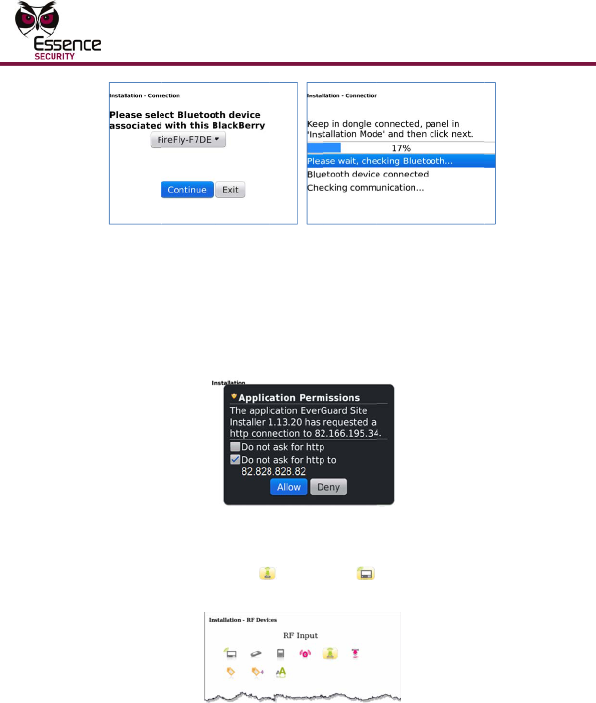
Figur
e
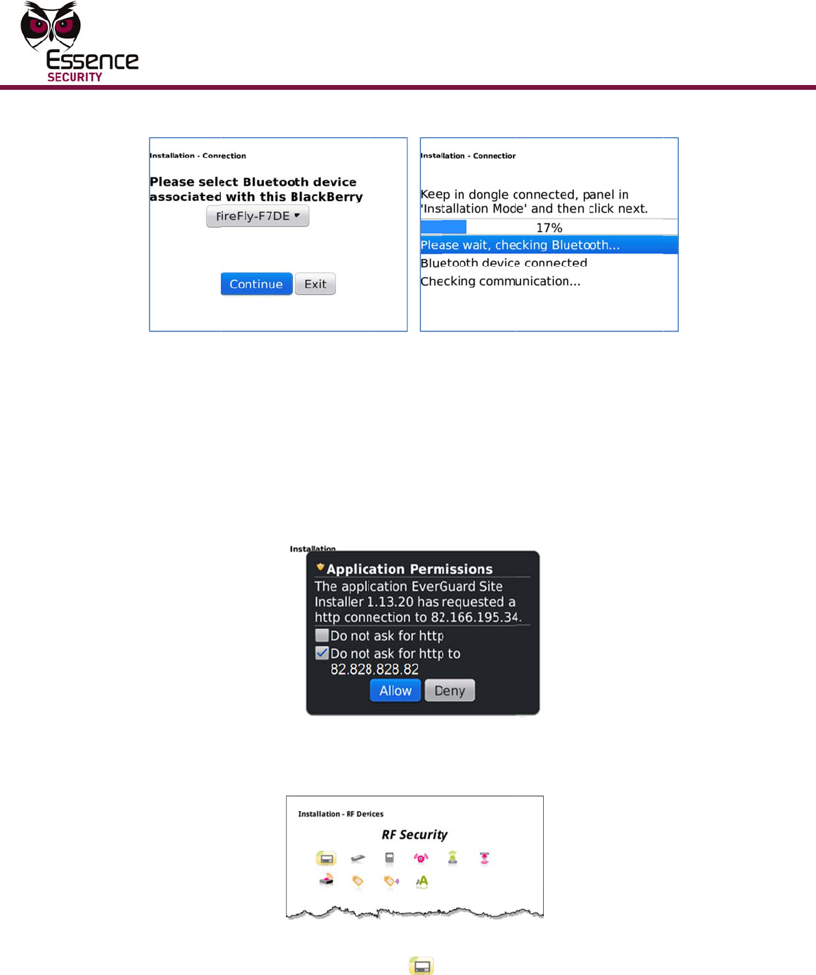
S
elect the
d
C
ommunic
a
b
etween th
e
T
he dongle
A
fter com
m
c
lick Contin
T
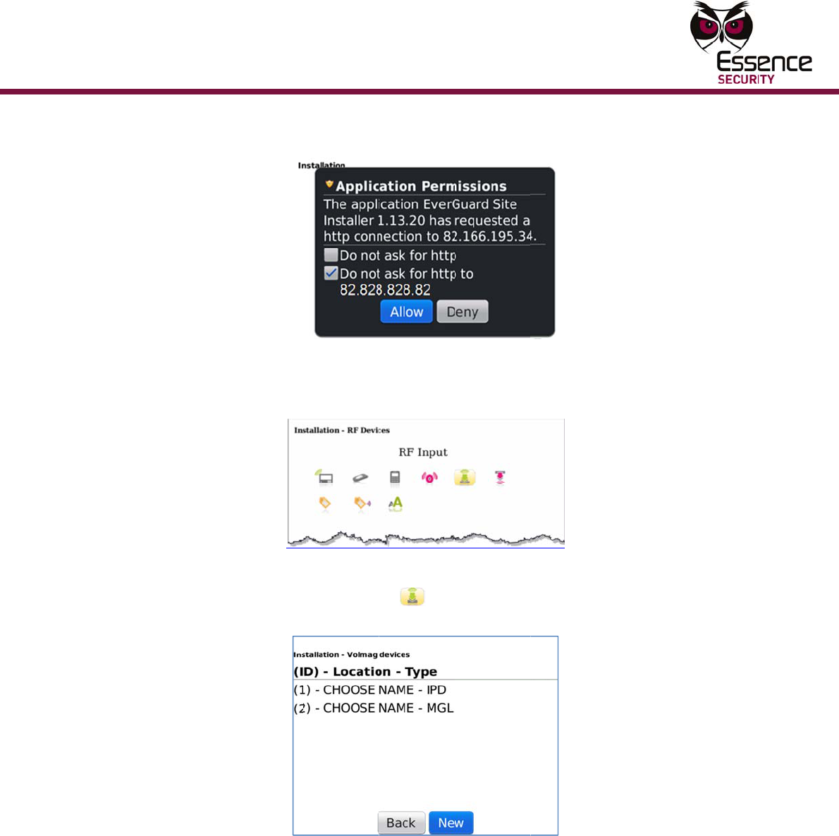
he server
s
pecific to
t
F
C
onfirm th
e
c
lick Allow.
Figure
6
S
elect the
R
M
GS and M
d
evice has
o
r, MG
L
de
p
n
guage an
d
e
4: Dongl
e
d
ongle ID f
r
a
tion scree
n
e
dongle a
n
ID is the l
a
m
unication
b
ue. The S
e
is located
a
t
he monito
r
F
igure 5: S
e
e
checkbox
The devic
e
6
: Device
T
R
F Security
GL devices
a
lready be
e
p
ending on
d
click Con
n
e
and Com
rom the dr
o
n
displays
a
n
d the Bla
c
a
st four nu
b
etween th
e
rver Permi
a
t the mon
r
ing statio
n
e
rver Perm
with the I
P
e
Types scr
T
ypes Scre
e
y
icon .
s
) already i
n
e
n installe
d
the devic
e
Mu
l
n
ect. The
D
m
unication
o
p-down li
s
a
nd procee
d
c
kBerry.
mbers on
t
e dongle a
n
ssions scr
e
itoring cen
t
n
.
issions Scr
e
P
address
o
een is disp
e
n - RF Se
c
A screen li
s
n
the syste
d
, it will ap
p
e
’s configu
r
Co
n
ti-Purpose
M
D
ongle scre
Screen
s
t and clic
k
d
s to esta
b
he barcod
e
n
d the Bla
c
e
en is displ
a
t
er.
T
he IP
e
en
o
f the serv
e
layed.
c
urity Icon
s
ting RF se
m is displa
y
p
ear in the
ation.
n
figuring
t
M
agnetic S
w
e
en is displ
a
k
Continue.
b
lish a con
n
e
glued to
t
c
kBerry is
s
a
yed.
address di
e
r is select
e
e
curity devi
yed. If an
list as an
M
t
he Devic
e
itch
a
yed.
A
n
ection
t
he dongle.
s
ynched,
splayed is
e
d and
ces (MGI,
R
F securit
y
M
GI, MGS
e
y
Configu
Multi-Pur
p
ring the
D
p
ose Magne
t
A
I
r
9.
C
l
e
10.
A
s
d
D
evice
t
ic Switch
Figu
r
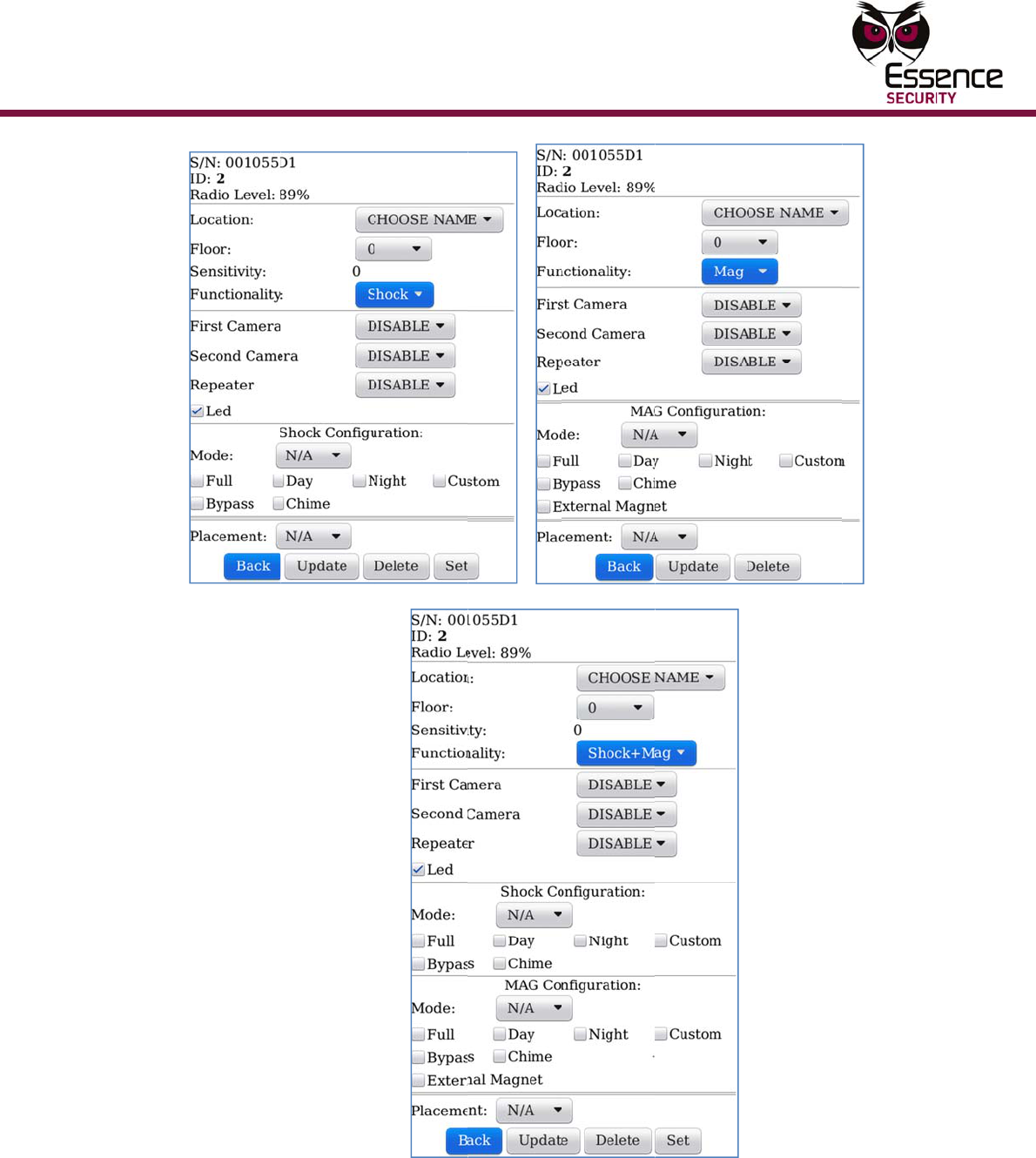
A
t this poin
When
A
the de
v
Sh
o
Se
t
Sh
o
Se
t
Ma
g
Se
t
an
d
de
t
ma
If
th
e
de
t
pe
r
ac
c
I
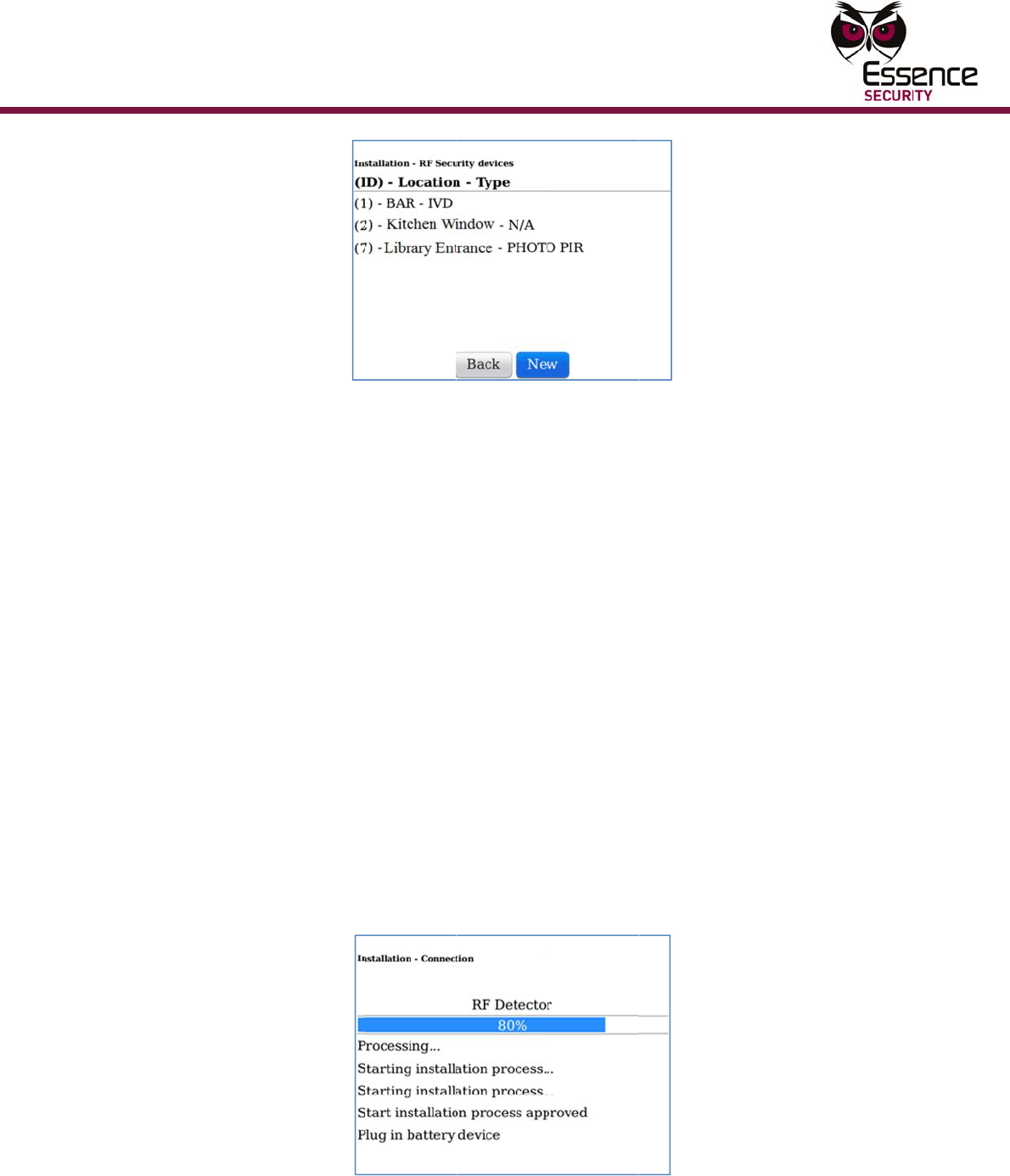
f there ar
e
r
eplaced b
y
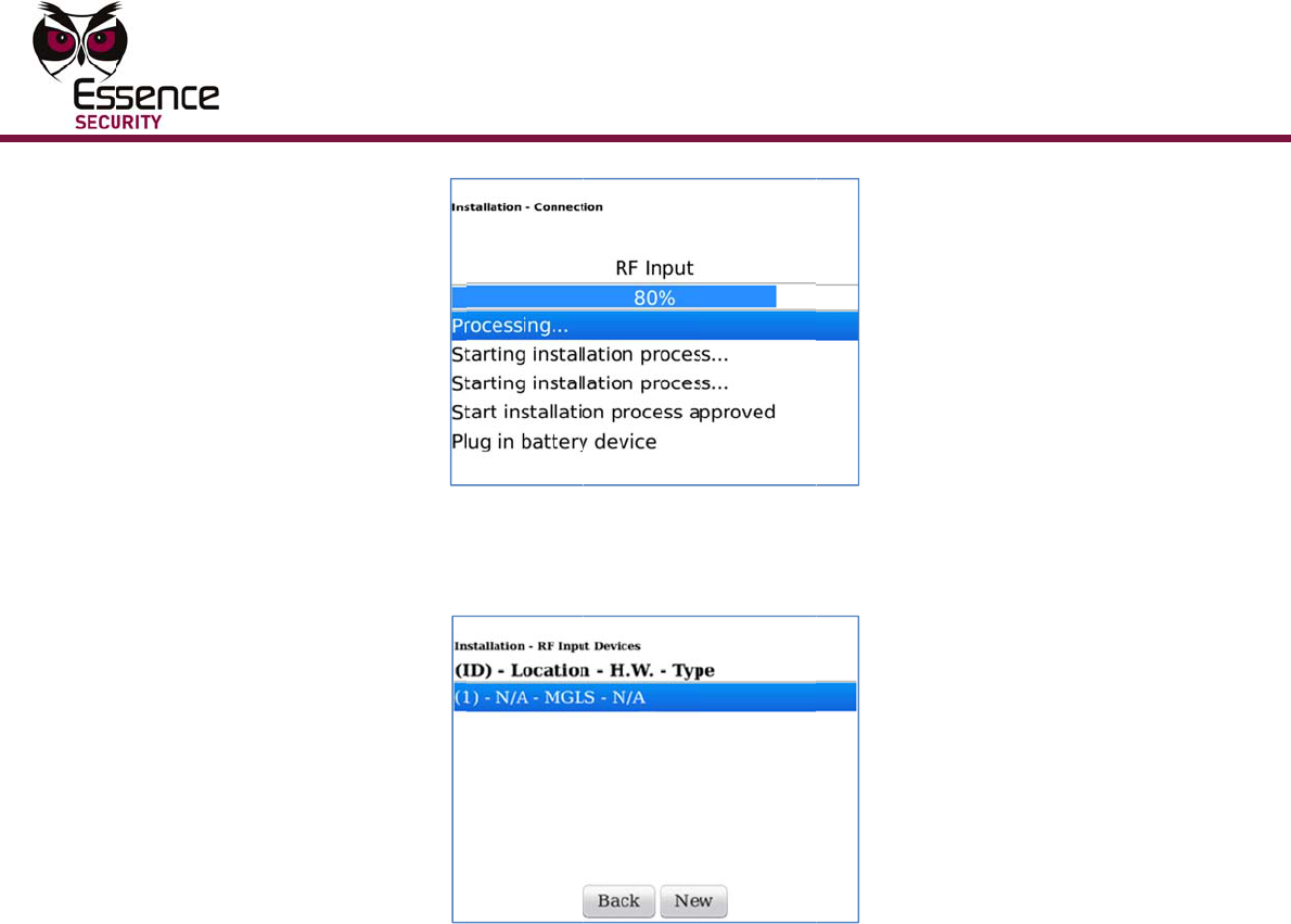
C
lick New,
a
e
arned by
t
A
fter the d
e
s
creen disp
d
evice row
r
e 7: RF S
e
t the follo
w
A
dding or
E
v
ice as foll
o
o
ck & Mag
n
t
the confi
g
o
ck sensor
t
the confi
g
g
net senso
t
the confi
g
d
t
ermine if
a
gnet, confi
e
re is no ex
t
ermine if t
r
imeter ma
g
c
ordingly.
no RF Se
c
y
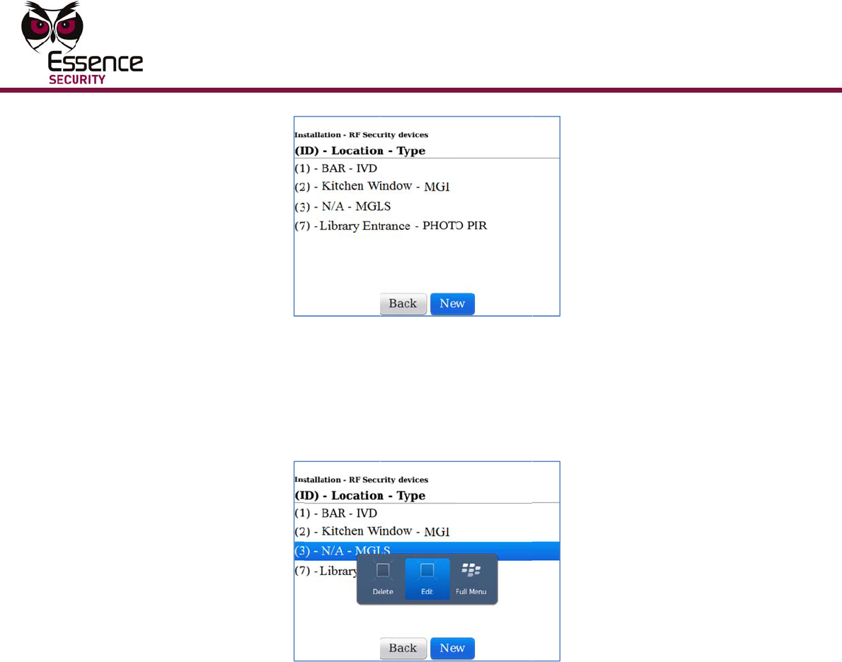
the word
“
a
nd then p
t
he syste
m
Figure 8:
S
e
vice is lea
r
lays again,
text is “N/
A
e
curity De
v
w
ing shoul
d
E
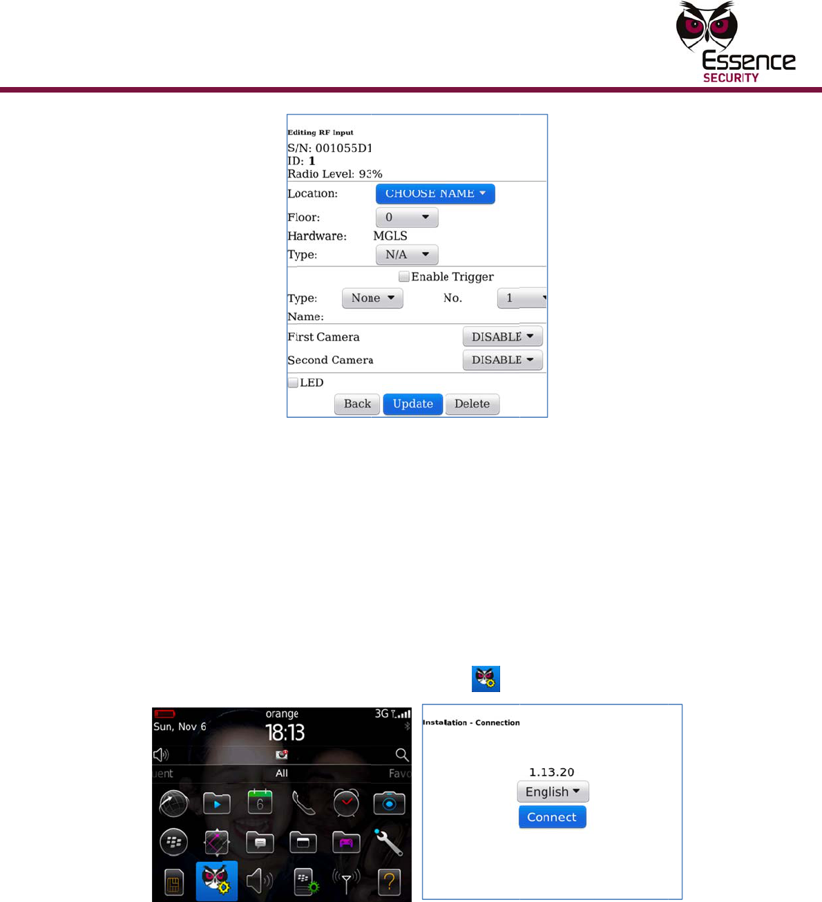
diting an
R
o
ws:
n
et sensor
g
uration fo
r
g
uration fo
r
o
r
g
uration fo
r
a
wired ext
e
gure the d
e
x
ternal wir
e
he integral
gnet or no
t
c
urity devic
“
EMPTY”.
ut a batter
y
m
.
S
ystem Le
a
r
ned by th
e
but with
a
A
– MGLS”
,
ice Listing
d
be consid
e
R
F security
r
the magn
e
r
the shock
r
the magn
e
e
rnal mag
n
e
vice acco
r
e
d magnet
c
magnet s
e
t
, and then
es currentl
y
y
in the de
v
a
rning Scre
e
e
system, t
a
new row
f
,
because i
t
Screen
e
red:
device pla
e
t sensor a
sensor.
e
t sensor
n
et will be
c
r
dingly.
c
onnected
t
e
nsor will f
u
configure
t
y
in the sy
s
v
ice as ins
t
e
n
he RF Sec
u
f
or the lear
n
t
has not b
e
n the func
t
a
nd the sh
o
c
onnected
t
t
o the devi
u
nction as
a
the device
s
tem, the l
t
ructed. Th
u
rity Devic
e
ned device
e
en name
d
1
1
t
ionality of
ck sensor.
t
o the
ce,
a
ist will be
e device is
e
Listing
. The new
d
yet.
1
12
Fig
T
w
t
11.
C
m
F
12.
E
T
s
s
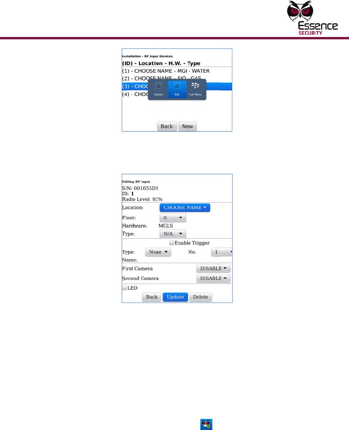
ure 9: Dev
T
he ID can
n
w
ere put in
t
he third R
F
C
lick the d
e
m
enu.
F
igure 10:
D
E
nter para
m
T
he locatio
n
s
creen. Th
e
s
creen to i
n
ice Name
a
n
ot be cha
n
the syste
m
F
Security
d
e
vice you j
u
D
evice Na
m
m
eter valu
e
n
selected
w
e
Function
s
n
clude the
p
a
nd ID Scr
e
n
ged and r
e
m
. For exa
m
d
evice put
u
st added
t
m
e and ID
S
e
s as requi
r
w
ill replac
e
s
elected wi
p
arameter
s
Mu
l
e
en with a
N
e
present t
h
m
ple, in th
e
i
n the syst
e
t
o the list a
S
creen wit
h
r
ed.
e
the N/A v
a
ll automati
s
relevant
f
Co
n
ti-Purpose
M
N
ew Devic
e
h
e order in
e
screen a
b
e
m.
nd select
E
h
Popup M
e
a
lue in the
c
ally chan
g
or the sele
c
n
figuring
t
M
agnetic S
w
e
Row
which the
d
b
ove the d
e
E
dit from t
h
e
nu
Device Na
g
e the Para
cted functi
o
t
he Devic
e
itch
d
evices
e
vice was
h
e popup
m
e and ID
meter
o
n.
e
Configu
Multi-Pur
p
Figur
e
ring the
D
p
ose Magne
t
e
11: RF S
e
D
evice
t
ic Switch
e
curity De
v
T
he S
/
param
the sy
s
per RF
v
ice Param
e
/
N (serial n
u
e
ters. The
s
s
tem. The
R
Security d
e
ter Scree
n
umber) an
d
s
e paramet
R
adio level
d
evice in th
e
n
s (Shock,
M
d
ID of the
ers are set
is also rea
e
system.
M
agnet an
d
device are
when the
d
d-only, it
s
d
Shock &
M
e
read-only
device is l
e
s
hows the
R
1
3
M
agnet)
e
arned by
R
SSI level
3
14
13.
A
a
a
14.
C
o
To ad
d
1.
I
s
b
2.
C
3.
F
T
4.
S
5.
S
C
b
T
6.
A
c
A
fter comp
l
a
ppears st
a
a
bout the
p
C
lick OK. T
h
o
n the list.
d
ES700
M
I
f the scre
w
s
crew with
b
etween th
e
C
onnect th
e
F
rom the B
l
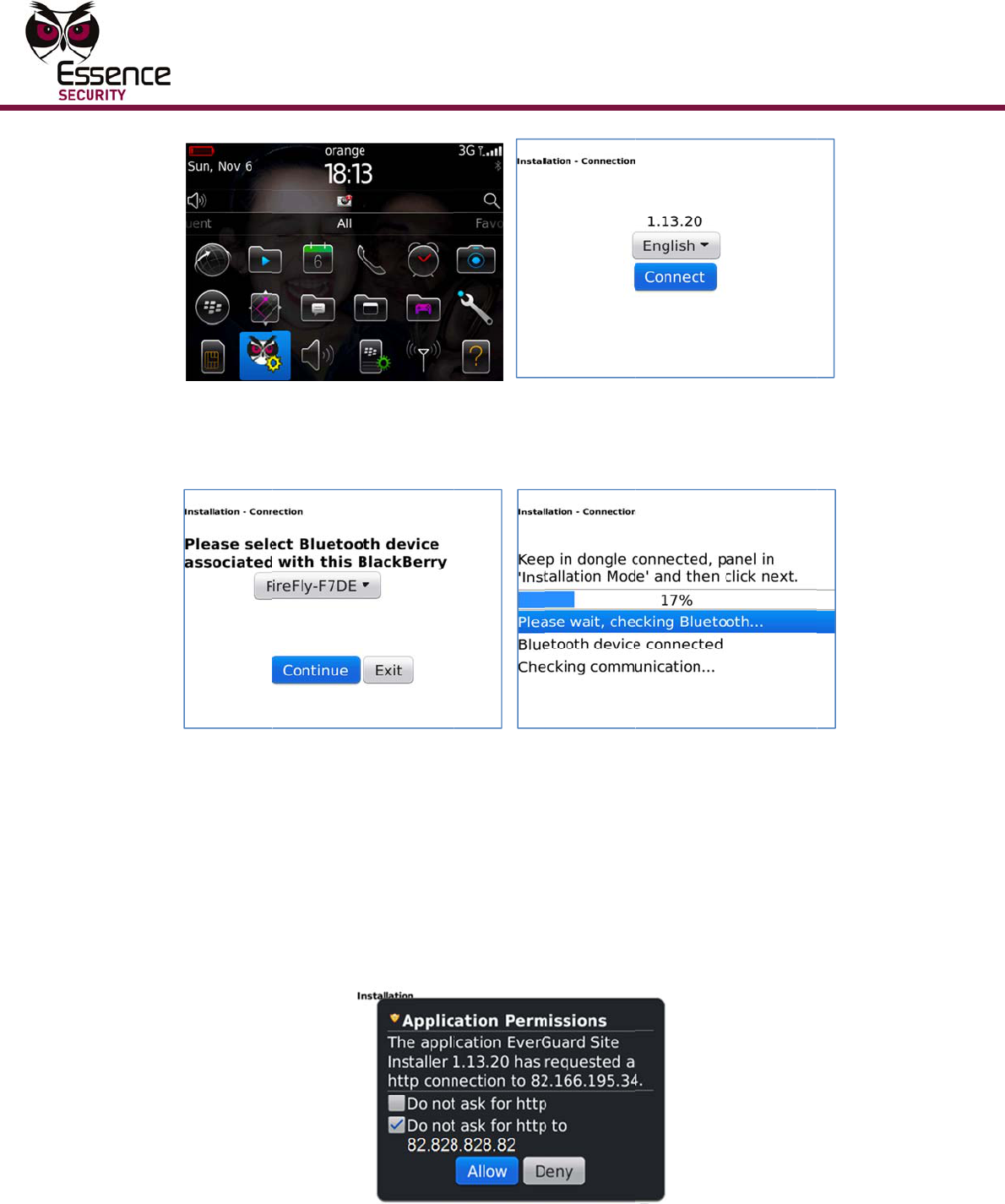
Figur
e
T
he Langu
a
S
elect a La
n
Figur
e
S
elect the
d
C
ommunic
a
b
etween th
e
T
he dongle
A
fter com
m
c
lick Contin
eting the
P
a
ting that t
h
p
arameters
,
h
e Installa
t
M
GLS a
s
w
securing
t
a flathead
e
side sna
p
e
dongle to
l
ackBerry,
c
e
12: Main
a
ge screen
n
guage an
d
e
13: Dong
l
d
ongle ID f
r
a
tion scree
n
e
dongle a
n
ID is the l
a
m
unication
b
ue. The S
e
P
arameters
h
e device
d
,
see the E
S
t
ion screen
s
an RF I
t
he top co
v
screwdrive
p
and the t
o
o
the syste
m
click the E
s
Menu and
is displaye
d
d
click Con
n
le and Co
m
rom the dr
o
n
displays
a
n
d the Bla
c
a
st four nu
b
etween th
e
rver Permi
Mu
l
screen, cli
d
ata updat
e
S
I-CMS Us
e
is display
e
nput de
v
v
er to the
m
r. Then ge
n
o
p cover a
n
m
Control
P
s
sence Site
Language
d
.
n
ect. The
D
m
municatio
n
o
p-down li
s
a
nd procee
d
c
kBerry.
mbers on
t
e dongle a
n
ssions scr
e
Co
n
ti-Purpose
M
c
k Update
e
d success
f
e
r Guide.
e
d and the
n
v
ice:
m
ounting is
n
tly insert
t
n
d pry off t
P
anel.
Installer i
c
S
creens
D
ongle scre
n
Screen
s
t and clic
k
d
s to esta
b
he barcod
e
n
d the Bla
c
e
en is displ
a
n
figuring
t
M
agnetic S
w
and Save.
f
ully. For in
new devic
e
present, r
e
t
he screwd
he cover.
c
on .
e
en is displ
a
k
Continue.
b
lish a con
n
e
glued to
t
c
kBerry is
s
a
yed.
t
he Devic
e
itch
A messag
e
formation
e
appears
e
move the
river
a
yed.
A
n
ection
t
he dongle.
s
ynched,
e
e
Configu
Multi-Pur
p
ring the
D
p
ose Magne
t
T
s
7.
C
c
8.
S
t
I
r
9.
C
t
D
evice
t
ic Switch
T
he server
s
pecific to
t
Fi
C
onfirm th
e
c
lick Allow.
Figure 1
S
elect the
R
t
he system
Fig
u
I
f there ar
e
r
eplaced b
y
C
lick New,
a
t
ext. The d
e
is located
a
t
he monito
r
gure 14: S
e
checkbox
The devic
e
5: Device
T
R
F Input ic
o
is display
e
u
re 16: RF
no RF Inp
u
y
the word
“
a
nd then p
e
vice is lea
a
t the mon
r
ing statio
n
S
erver Per
m
with the I
P
e
Types scr
T
ypes Scre
o
n . A
s
e
d.
Input Devi
c
ut devices
“
EMPTY”.
ut a batter
y
rned by th
e
itoring cen
t
n
.
m
issions Sc
r
P
address
o
een is disp
en - RF Se
c
s
creen listi
n
c
e Listing
S
currently i
n
y
in the de
v
e
system.
t
er.
T
he IP
r
een
o
f the serv
e
layed.
c
urity Icon
n
g RF Inpu
t
S
creen
n
the syste
v
ice, as di
r
address di
e
r is select
e
t
devices a
m, the list
r
ected by t
h
1
5
splayed is
e
d and
lready in
will be
h
e screen
5
16
10.
A
d
T
w
w
11.
C
W
w
A
F
A
fter the d
e
d
isplayed.
Fi
g
T
he ID can
n
w
ere learn
e
w
as the thi
r
C
hoose a n
a
W
hen sele
c
w
here the
d
A
nd then cl
Back t
o
device
menu.
Enter
p
A mes
s
For inf
F
igure 17:
e
vice is lea
r
g
ure 18: D
e
n
ot be cha
n
e
d by the s
y
r
d RF secu
r
a
me
/
locati
o
ting a nam
d
evice will
b
ick:
o
return to
you just a
d
p
arameter
v
s
age appe
a
o
rmation a
System Le
a
r
ned by th
e
e
vice Nam
e
n
ged and r
e
y
stem. For
r
ity device
o
n for the
d
m
e for the d
b
e mounte
d
the scree
n
dded to th
e
values as
r
a
rs stating
t
bout the p
a
Mu
l
a
rning Scr
e
e
system,
a
e
and ID S
c
e
present t
h
example,
i
learned by
d
evice.
evice, bas
e
d
.
n
listing RF
e
list and s
e
r
equired, a
n
t
hat the d
e
a
rameters,
Co
n
ti-Purpose
M
e
en
a
Device N
a
c
reen
h
e order in
i
n the scre
e
the syste
m
e
the decisi
Input devi
c
e
lect Edit f
r
n
d then cli
c
e
vice data
u
see the E
S
n
figuring
t
M
agnetic S
w
a
me and I
D
which the
d
e
n above t
h
m
.
on on the
l
c
es. Doubl
e
rom the p
o
c
k Update
a
u
pdated su
c
S
I-CMS Us
e
t
he Devic
e
itch
D
screen is
d
evices
h
e device
ocation
e
click the
o
pup
a
nd Save.
c
cessfully.
e
r Guide.
e
Configu
Multi-Pur
p
ring the
D
p
ose Magne
t
To ed
i
1.
C
2.
C
T
3.
S
D
evice
t
ic Switch
Figur
e
T
he S
/
param
the sy
s
per RF
Click
O
appea
r
New t
o
i
t an ES
7
C
onnect th
e
C
lick the E
s
Figu
r
T
he Langu
a
S
elect a La
n
e
19: RF In
/
N (serial n
u
e
ters. The
s
s
tem. The
R
Input dev
i
O
K. The Ins
r
s on the li
s
o
add an a
d
7
00MGL
S
e
dongle to
s
sence Site
r
e 20: Mai
n
a
ge screen
n
guage an
d
n
put Devic
e
umber) an
d
s
e paramet
R
adio level
i
ce in the s
s
tallation s
c
s
t.
d
ditional d
e
S
device
o
the syste
m
Installer i
c
n
Menu and
is displaye
d
d
click Con
n
e
Paramete
r
d
ID of the
ers are set
is also rea
ystem.
c
reen is dis
p
e
vice.
(RF Sec
m
Control
P
c
on o
n
Language
d
.
n
ect. The
D
r
Screen
device are
when the
d
d-only, it
s
p
layed and
u
rity or
P
anel.
n
the Black
B
Screen
D
ongle scre
e
read-only
device is l
e
s
hows the
R
the new d
RF Inpu
t
B
erry.
e
en is displ
a
1
7
e
arned by
R
SSI level
evice
t
):
a
yed.
7
18
4.
S
C
b
T
5.
A
c
T
s
6.
C
c
7.
S
d
a
8.
C
a
Figur
e
S
elect the
d
C
ommunic
a
b
etween th
e
T
he dongle
A
fter com
m
c
lick Contin
T
he server
s
pecific to
t
Fi
C
onfirm th
e
c
lick Allow.
S
elect the
R
d
evice was
a
lready in t
C
lick the it
e
a
ppears.
e
21: Dong
l
d
ongle ID f
r
a
tion scree
n
e
dongle a
n
ID is the l
a
m
unication
b
ue. The S
e
is located
a
t
he monito
r
gure 22: S
e
checkbox
The devic
e
R
F input
previously
he system
Figure 23
e
m row of
t
le and Co
m
rom the dr
o
n
displays
a
n
d the Bla
c
a
st four nu
b
etween th
e
rver Permi
a
t the mon
r
ing statio
n
S
erver Per
m
with the I
P
e
Types scr
or RF S
e
defined. A
is display
e
3
: Device T
y
t
he device
t
Mu
l
m
municatio
n
o
p-down li
s
a
nd procee
d
c
kBerry.
mbers on
t
e dongle a
n
ssions scr
e
itoring cen
t
n
.
m
issions Sc
r
P
address
o
een is disp
e
curity
screen lis
t
d.
y
pes Scree
t
hat will b
e
Co
n
ti-Purpose
M
n
Screen
s
t and clic
k
d
s to esta
b
he barcod
e
n
d the Bla
c
e
en is displ
a
t
er.
T
he IP
r
een
o
f the serv
e
layed.
icon, depe
ing device
s
n
edited. A
p
n
figuring
t
M
agnetic S
w
k
Continue.
b
lish a con
n
e
glued to
t
c
kBerry is
s
a
yed.
address di
e
r is select
e
nding on h
s
of the sp
e
popup me
n
t
he Devic
e
itch
A
n
ection
t
he dongle.
s
ynched,
splayed is
e
d and
ow the
e
cified typ
e
n
u
e
e
Configu
Multi-Pur
p
ring the
D
p
ose Magne
t
9.
S
d
G
10.
C
m
T
T
R
s
11.
C
r
To de
l
1.
C
2.
C
D
evice
t
ic Switch
Figu
S
elect Edit
d
isplayed.
F
G
uide.
Figur
e
C
hange pa
r
m
essage a
p
T
he S/N (s
e
T
hese para
m
R
adio level
s
ystem.
C
lick OK. T
h
r
ow is upd
a
l
ete an
E
C
onnect th
e
C
lick the E
s
re 24: De
v
in the pop
u
F
or inform
a
e
25: RF In
r
ameter val
p
pears stat
e
rial numb
e
m
eters are
is also rea
d
h
e Installa
t
a
ted accord
E
S700M
G
e
dongle to
s
sence Site
v
ice Listing
u
p menu.
T
a
tion about
n
put Devic
e
l
ues as req
ing that th
e
e
r) and ID
set when
t
d
-only, it s
t
ion screen
ingly.
G
LS devi
c
the syste
m
Installer i
c
with Popu
p
T
he param
e
the para
m
e
Paramete
r
uired and
c
e
device d
a
of the devi
t
he device
hows the
R
is display
e
c
e (RF S
m
Control
P
c
on o
n
p
Menu
e
ters of the
eters, see
r
Screen
c
lick Updat
e
a
ta update
d
c
e are rea
d
is learned
b
R
SSI level
p
e
d and the
p
ecurity
o
P
anel.
n
the Black
B
selected d
the ESI-C
M
e
and Sav
e
d
successf
u
d
-only para
by the sys
t
p
er device
t
previously
o
r RF In
p
B
erry.
1
9
evice are
M
S User
e
. A
lly.
meters.
t
em. The
t
ype in the
selected
p
ut):
9
20
T
3.
S
4.
S
C
b
T
5.
A
c
T
s
6.
C
c
Figur
e
T
he Langu
a
S
elect a La
n
Figure
S
elect the
d
C
ommunic
a
b
etween th
e
T
he dongle
A
fter com
m
c
lick Contin
T
he server
s
pecific to
t
Fi
C
onfirm th
e
c
lick Allow.
e
26: Main
a
ge screen
n
guage an
d
27: Dongl
e
d
ongle ID f
r
a
tion scree
n
e
dongle a
n
ID is the l
a
m
unication
b
ue. The S
e
is located
a
t
he monito
r
gure 28: S
e
checkbox
The devic
e
Menu and
is displaye
d
d
click Con
n
e
and Com
rom the dr
o
n
displays
a
n
d the Bla
c
a
st four nu
b
etween th
e
rver Permi
a
t the mon
r
ing statio
n
S
erver Per
m
with the I
P
e
Types scr
Mu
l
Language
d
.
n
ect. The
D
municatio
n
o
p-down li
s
a
nd procee
d
c
kBerry.
mbers on
t
e dongle a
n
ssions scr
e
itoring cen
t
n
.
m
issions Sc
r
P
address
o
een is disp
Co
n
ti-Purpose
M
S
creens
D
ongle scre
Screens
s
t and clic
k
d
s to esta
b
he barcod
e
n
d the Bla
c
e
en is displ
a
t
er.
T
he IP
r
een
o
f the serv
e
layed.
n
figuring
t
M
agnetic S
w
e
en is displ
a
k
Continue.
b
lish a con
n
e
glued to
t
c
kBerry is
s
a
yed.
address di
e
r is select
e
t
he Devic
e
itch
a
yed.
A
n
ection
t
he dongle.
s
ynched,
splayed is
e
d and
e
Mounti
n
Multi-Pur
p
5
5.1
n
g
p
ose Magne
t
7.
S
w
a
8.
C
9.
S
10.
C
p
Mo
u
Inst
a
(as
S
The ES
7
smart
m
A single
activate
50131
s
strengt
h
When i
n
settings
an exte
r
ES700
M
t
ic Switch
S
elect the
R
w
as previo
u
a
lready in t
C
lick the it
e
Figu
S
elect one
o
Delete
Edit a
n
C
onfirm th
e
p
reviously
s
u
ntin
g
a
lling
t
S
hock
7
00MGLS d
m
agnet sen
s
screw ma
y
the tear-
o
s
tandard).
A
h
and sym
m
n
stalling th
e
provides
y
r
nal legacy
M
GLS devic
e
Figure 29
R
F input
u
sly define
d
he system
e
m row of
a
re 30: De
v
o
f the follo
w
n
d then cli
c
e
delete op
e
s
elected ro
w
g
t
he E
S
Senso
e
vice is m
o
s
or and th
e
y
be added
ff tamper
p
A
second o
m
etry of th
e
e
ES700M
G
y
ou with th
e
magnet d
e
e
as if it w
a
9
: Device T
y
or Secu
r
d
. A screen
is display
e
a
device. A
v
ice Listing
w
ing men
u
c
k Delete i
n
e
ration. Th
w
is remo
v
S
700M
G
o
r and
/
o
unted usi
n
e
correspo
n
to the mo
u
p
rotection
f
ptional scr
e
e
installati
o
G
LS device
e
option of
e
vice. The
e
a
s defined
a
y
pes Scree
r
ity ico
listing de
v
d.
popup me
n
with Popu
p
items:
n
the Devic
e
e Installati
v
ed.
G
LS D
e
/
or M
a
n
g mountin
g
n
ding perm
a
u
nting par
t
f
or the dev
e
w may be
o
n See Fig
u
as an mag
n
using the
d
e
xternal m
a
a
s an RF I
n
n
n
, dependi
n
v
ices of the
n
u appear
s
p
Menu
e
Paramet
e
o
n screen i
e
vice
gnet
D
g
tape fou
n
a
nent mag
t
of the sm
a
i
ce (and b
e
added for
u
re 32 and
n
et detect
o
d
evice as
a
a
gnet mus
t
put device
n
g on how
e
specified
t
s
.
e
rs screen.
i
s displaye
d
D
etect
o
n
d on the
b
net.
a
rt magne
t
e
complian
t
the mecha
step
5 bel
o
o
r, the con
f
a
n input te
r
t
be hardw
(see Figur
2
1
the device
t
ype
d
and the
o
r)
b
ack of the
t
sensor to
t
to the EN
nical
o
w.
f
iguration
r
minal for
i
red to the
e 37 and
1
22
Figure
3
externa
To in
s
(as S
h
1.
I
c
2.
I
s
s
Figu
r
3.
I
b
i
I
m
t
Figur
A
i
3
8). This m
l magnet d
s
tall the
h
ock Se
n
I
dentify th
e
c
riteria in s
e
I
f the scre
w
s
crew with
s
ide snap a
r
e 31: Scr
e
S
w
S
P
w
Figure 32:
I
f there is
n
b
attery mu
s
ndicators
o
I
f the batte
m
echanism
t
he battery
e 33: Loca
t
A
fter the b
a
ndicates t
h
eans place
m
e
vice.
E
S700M
G
n
sor and
/
e
location f
o
e
ction 3.3.
w
securing
t
a screwdri
v
nd the top
e
wdriver In
s
S
crew 2: For firm
c
w
ith the mounting
S
crew 1: For Tear-
P
rotection and fir
m
w
ith the mounting
Tear-Off T
n
o battery i
s
t be a 3V
C
o
n the batt
e
ry is alrea
d
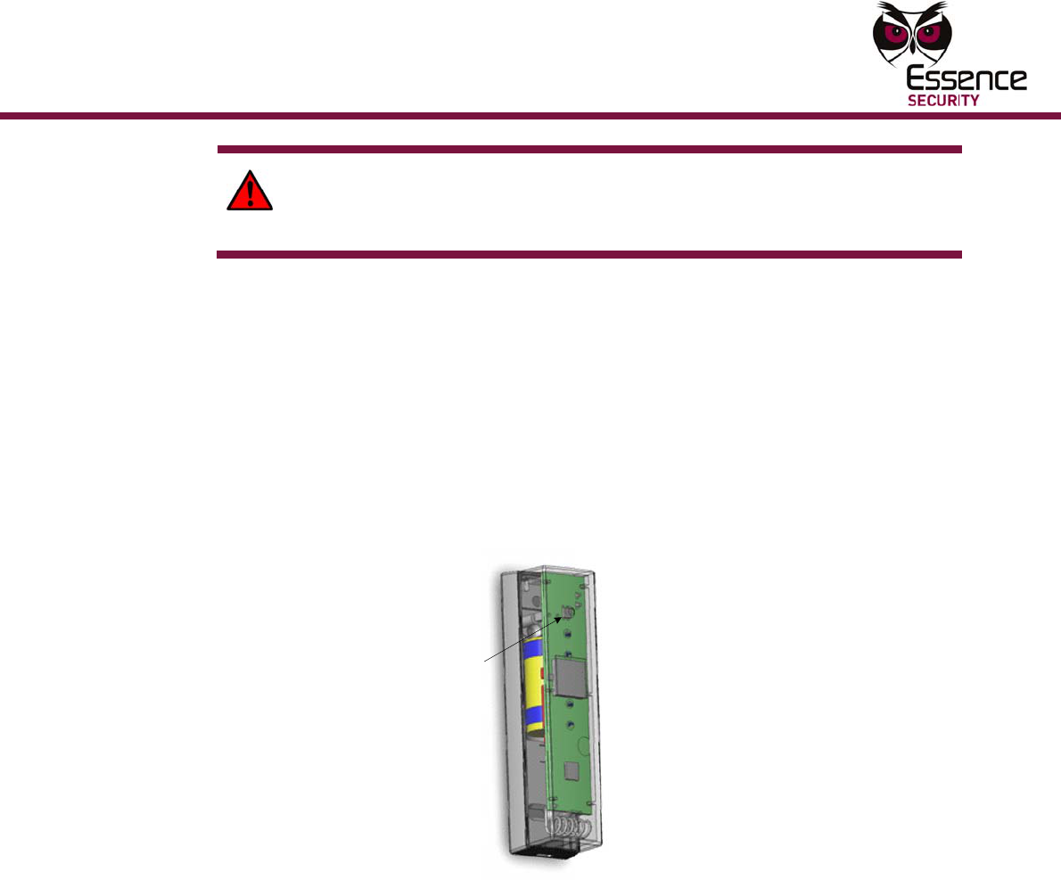
by pressi
n
making su
t
ion of the
a
ttery is in
s
h
at the dev
i
ment of th
e
G
LS dev
/
or Ma
g
o
r mountin
g
t
he top co
v
v
er. Then
g
cover and
s
ertion Poi
n
contact
surface
-
Off/Tamper
m
contact
surface
2
1
amper Scr
e
n the devi
c
C
R
-123A L
e
ry match
t
d
y in the d
e
n
g the tam
p
u
re the pol
a
T
S
ES700MG
L
s
talled, the
ice has be
e
Mu
l
e
ES700M
G
ice
net Det
e
g
the ES7
0
v
er to the
m
g
ently inse
r
pry off the
n
t and Top
e
w Locatio
n
c
e, put the
ithium bat
t
t
he picture
e
vice, rem
o
p
er switch
s
a
rity is corr
e
T
amper
S
witch
L
S Device
T
red LED g
e
n success
f
ti-Purpose
M
G
LS device
e
ctor):
0MGLS de
v
m
ounting is
r
t the scre
w
cover.
Cover Sep
n
in Mounti
battery in
t
t
ery. Chec
k
on the de
v
o
ve it and t
s
everal tim
e
ct.
T
amper Me
c
l
ows for 3
s
ully power
e
M
agnetic S
w
must be n
e
v
ice accord
present, r
e
w
driver bet
w
aration
ng
the device
.
k
that the
p
v
ice circuit
t
rigger the
t
es, and th
e
c
hanism
s
econds. T
h
e
d up.
Mounting
itch
e
ar the
ing the
e
move the
w
een the
.
The
olarity
board.
t
amper
e
n replace
h
is
Mounti
n
Multi-Pur
p
n
g
p
ose Magne
t
W
R
b
4.
C
l
o
5.
M
t
(
T
s
3
6.
F
w
7.
R
c
8.
L
t
p
g
s
m
p
T
i
m
r
i
u
t
ic Switch
W
ARNING
R
eplace th
e
b
y the man
C
lean the s
o
cations a
r
M
ount the
s
t
ape and p
r
(
frame-sid
e
T
o ensure
a
s
crew the
m
3
5 DIN 79
8
F
or standa
r
w
ill add a t
e
Figur
e
R
eplace th
e
c
ompliant i
n
L
ine up the
t
he indicat
o
p
ermanent
g
reen LED.
s
ensor app
r
m
agnet by
p
lace.
T
he distan
c
nstallation
m
olding on
r
equire the
n another
i
u
sually be
a
! A new ba
e
battery o
n
ufacturer.
urfaces of
t
r
e dry.
s
mart mag
n
r
ess the sti
c
e
of the op
e
a
strong bo
m
ounting i
n
8
2 C screw
s
r
d complia
n
e
aring tam
p
LE
D
Indica
e
34: ES70
0
e
top cover
n
stallation,
permanen
o
r marks a
r
magnet b
a
From this
p
r
oximately
peeling th
e
c
e between
to installa
t
a frame o
r
sensor to
b
nstallation
a
round 3 c
m
a
ttery can
e
n
ly with th
e
Discard us
e
t
he mounti
n
et sensor
c
ky side a
g
e
ning).
nd and to
e
n
place, aft
e
s
as depict
e
n
t installati
o
per protec
t
D
a
to
r
0
MGLS De
v
of the dev
use a kb2
2
t magnet
n
r
e aligned.
a
ck and for
t
point, mov
0.5 cm (0.
e
cover off
the two p
a
t
ion, depen
r
a deviati
o
b
e closer t
o
. As a gen
e
m
from ea
c
e
xplode if i
t
e
same or
e
e
d batterie
ng locatio
n
by peeling
g
ainst surf
a
e
nable the
e
r using th
e
e
d in Figur
e
o
ns, a sing
l
t
ion to the
v
ice Interio
ice onto th
e
2
X6 screw
n
ext to the
T
hough tri
a
t
h until yo
u
e the per
m
2 inch).
Th
the mount
i
a
rts of the
d
ding on th
e
o
n between
o
the perm
a
e
ral rule, t
h
c
h other.
t
is incorre
c
e
quivalent
t
s
responsi
b
s thoroug
h
the cover
o
ce of the d
Tear-Off/T
a
e
mountin
g
e
32.
l
e screw m
u
u
nit.
r View 1
e
bottom c
a
to supple
m
smart ma
g
a
l and erro
r
u
find the t
h
m
anent ma
g
en Mount
t
ng tape an
d
evice ma
y
e
surfaces.
the plane
s
a
nent mag
n
h
e two part
s
c
tly install
e
t
ype reco
m
b
ly.
h
ly. Make s
off the mo
u
d
esignated
T
amper fea
t
g
tape, wit
h
ust be add
e
asing. For
m
ent the cli
g
net senso
r
r, move th
e
h
reshold p
o
g
net towar
d
t
he perma
n
n
d pressing
y
vary fro
m
For exam
p
s
of the su
r
net than it
s of the de
2
3
d.
m
mended
u
re the
u
nting
location
t
ure, also
h
two 3 X
e
d. This
s
tandard
p.
r
so that
e
o
int of the
d
the smar
t
n
ent
it into
m
p
le,
faces may
would be
v
ice will
3
t
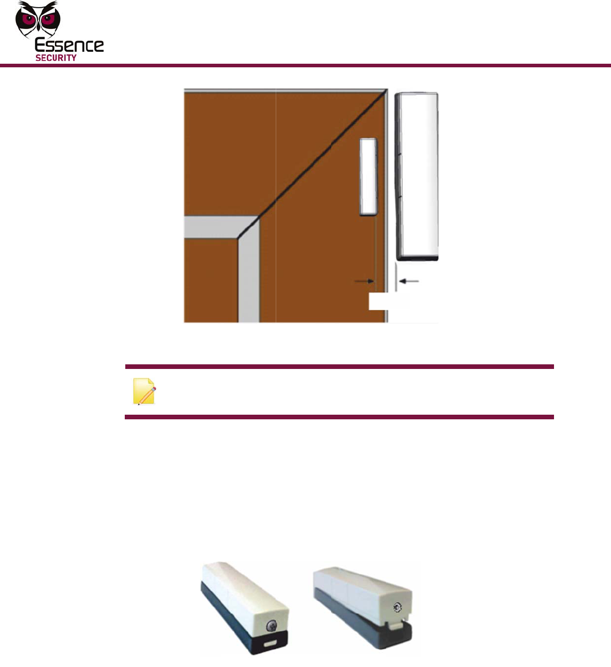
24
Figure
35: Corre
c
N
p
To in
s
Only)
:
1.
I
c
2.
I
s
s
Figu
r
3.
T
m
D
t
t
c
t ES700M
G
Marks
a
N
ote: If th
e
p
ermanent
s
tall the
:
I
dentify th
e
c
riteria in s
e
If
the scre
w
s
crew with
s
ide snap a
r
e 36: Scr
e
T
hread the
m
ounting (
s
D
epending
t
he tab cov
t
he tabs, u
s
G
LS-GN Ali
g
a
re Exagge
r
e
device is
magnet is
E
S700M
G
e
location f
o
e
ction 3.3.
w
securing
t
a screwdri
v
nd the top
e
wdriver In
s
leads from
s
ee Figure
on the typ
e
er of the t
a
s
e needle
n
g
nment an
r
ated for B
e
being use
d
not requir
e
G
LS dev
o
r mountin
g
t
he top co
v
v
er. Then
g
cover and
s
ertion Poi
n
the exter
n
37).
e
of wire fr
a
b that bes
n
ose pliers
Mu
l
~ 3
d Gap for
I
e
tter Unde
r
d
exclusive
l
e
d.
ice (as
a
g
the ES7
0
v
er to the
m
g
ently inse
r
pry off the
n
t and Top
n
al device
t
om the ex
t
t suits the
ti-Purpose
M
cm
ntrusion D
e
r
standing)
l
y as a Sho
a
n Input
0MGLS de
v
m
ounting is
r
t the scre
w
cover.
Cover Sep
hrough th
e
t
ernal devi
c
wire place
m
M
agnetic S
w
etection (
A
o
ck detecto
Termin
a
v
ice accord
present, r
e
w
driver bet
w
aration
e
back of t
h
c
e, carefull
y
m
ent. To b
r
Mounting
itch
A
lignment
r
, the
a
l
ing the
e
move the
w
een the
h
e
y
break off
r
eak off
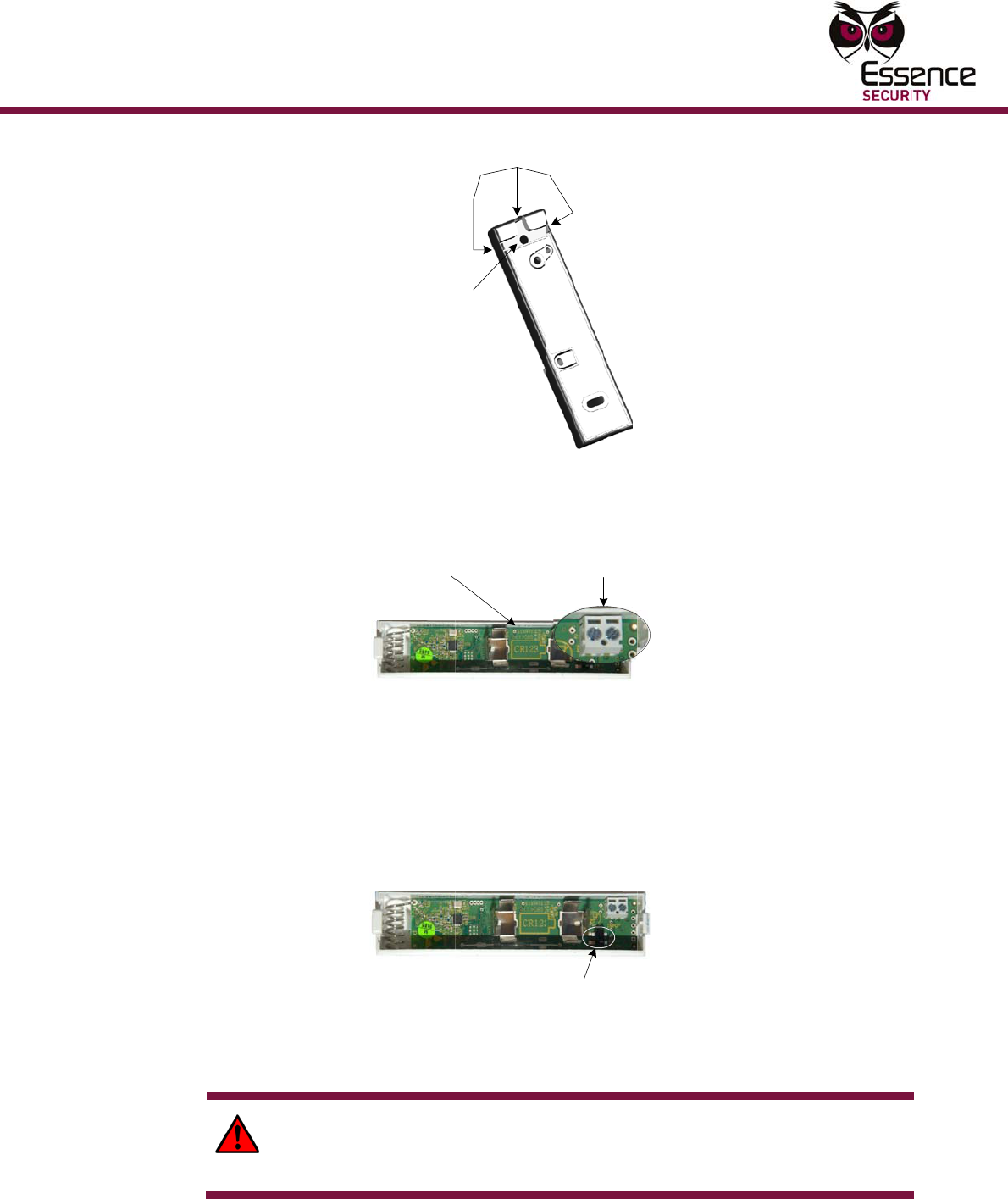
Mounti
n
Multi-Pur
p
n
g
p
ose Magne
t
Fig
u
4.
C
s
Fig
u
5.
I
b
i
I
m
t
Figur
A
i
W
R
b
t
ic Switch
u
re 37: Ext
C
onnect th
e
s
crewdrive
r
u
re 38: Ext
e
I
f there is
n
b
attery mu
s
ndicators
o
I
f the batte
m
echanism
t
he battery
e 39: Loca
t
A
fter the b
a
ndicates t
h
W
ARNING
R
eplace th
e
b
y the man
Thread Le
a
through H
o
ernal Lead
s
e
leads to t
r
. Polarity i
s
Batt
e
Compa
r
e
rnal Lead
s
n
o battery i
s
t be a 3V
C
o
n the batt
e
ry is alrea
d
by pressi
n
making su
t
ion of the
a
ttery is in
s
h
at the dev
i
! A new ba
e
battery o
n
ufacturer.
Tabs for
Leads
a
d
s
o
le
s
Placeme
n
t
he termin
a
s
irrelevan
t
e
r
y
r
tment
s
Placeme
n
n the devi
c
C
R
-123A L
e
ry match
t
d
y in the d
e
n
g the tam
p
u
re the pol
a
T
S
ES700MG
L
s
talled, the
ice has be
e
a
ttery can
e
n
ly with th
e
Discard us
e
n
t in the E
S
a
ls in the E
S
t
.
Terminals fo
r
External Lead
s
n
t in the ES
c
e, put the
ithium bat
t
t
he picture
e
vice, rem
o
p
er switch
s
a
rity is corr
e
T
amper
S
witch
L
S Device
T
red LED g
e
n success
f
e
xplode if i
t
e
same or
e
e
d batterie
S
700MGLS
d
S
700MGLS
s
700MGLS
D
battery in
t
t
ery. Chec
k
on the de
v
o
ve it and t
s
everal tim
e
ct.
T
amper Me
c
l
ows for 3
s
ully power
e
t
is incorre
c
e
quivalent
t
s
responsi
b
d
evice
device wit
h
D
evice
the device
.
k
that the
p
v
ice circuit
t
rigger the
t
es, and th
e
c
hanism
s
econds. T
h
e
d up.
c
tly install
e
t
ype reco
m
b
ly.
2
5
h
a
.
The
olarity
board.
t
amper
e
n replace
h
is
d.
m
mended
5

26
5.1.1
5.1.2
6.
C
s
7.
M
t
(
T
s
3
8.
F
w
9.
R
c
“Wal
After th
e
automa
t
test the
environ
m
the LED
enable/
d
Verif
y
If ES70
0
progra
m
Panel t
o
Manual.
Alterna
t
informa
t
Figur
e
C
lean the s
s
ure the lo
c
M
ount the
s
t
ape and p
r
(
frame-sid
e
T
o ensure
a
s
crew the
m
3
5 DIN 79
8
F
or standa
r
w
ill add a t
e
R
eplace th
e
c
ompliant i
n
k Test
”
e
battery h
t
ically runs
sensor for
m
ent as sp
s will alwa
y
d
isable co
n
y
High
-
0
KPD is av
a
m
92 functi
o
o
the ES70
0
)
t
ively, use
t
t
ion, see t
h
LE
D
Indica
e
40: ES70
0
urface of t
h
c
ations are
s
mart mag
n
r
ess the sti
c
e
of the op
e
a
strong bo
m
ounting i
n
8
2 C screw
s
r
d complia
n
e
aring tam
p
e
top cover
n
stallation,
”
Mode
as been in
s
for 10 mi
n
trigger ac
t
ecified by
t
y
s indicate
figuration.
-
Q
ualit
y
a
ilable: At
t
o
n, verify t
h
0
MGLS dev
t
he RF Tes
t
h
e ES700D
V
D
a
to
r
0
MGLS De
v
h
e designa
t
dry.
n
et sensor
c
ky side a
g
e
ning).
nd and to
e
n
place, aft
e
s
as depict
e
n
t installati
o
per protec
t
of the dev
use a kb2
2
s
talled in t
h
n
utes. In t
h
t
ions. The
L
t
he design
a
a trigger r
e
y
RF Co
t
he mounti
hat there i
s
ice. (For m
t
Mode in t
h
V
K User G
u
Mu
l
v
ice Interio
t
ed mounti
by peeling
g
ainst surf
a
e
nable the
e
r using th
e
e
d in Figur
e
o
ns, a sing
l
t
ion to the
ice onto th
e
2
X6 screw
h
e device,
a
h
is mode, t
h
L
EDs will i
n
a
ted functi
o
e
sponse, r
e
mmuni
ng locatio
n
s
sufficient
ore inform
a
h
e ES700D
u
ide.)
ti-Purpose
M
r View 1
n
g location
the cover
o
ce of the d
Tear-Off/T
a
e
mountin
g
e
32.
l
e screw m
u
u
nit.
e
bottom c
a
to supple
m
a
Walk Tes
h
e professi
o
dicate a c
h
o
n of the d
e
e
gardless o
cation
n
, using th
e
reception
f
a
tion, see
t
VK keypad
M
agnetic S
w
n
s thoroug
h
off the mo
u
d
esignated
T
amper fea
t
g
tape, wit
h
ust be add
e
asing. For
m
ent the cli
s
t mode (li
k
onal install
h
ange to th
e
vice. In t
h
o
f the LED’
s
(Optio
n
e
ES700KP
D
f
rom the C
o
t
he ES700
K
(For more
Mounting
itch
h
ly. Make
u
nting
location
t
ure, also
h
two 3 X
e
d. This
s
tandard
p.
k
e in PIRs)
er may
e
h
is mode,
s
n
al)
D
key pad
o
ntrol
K
PD User
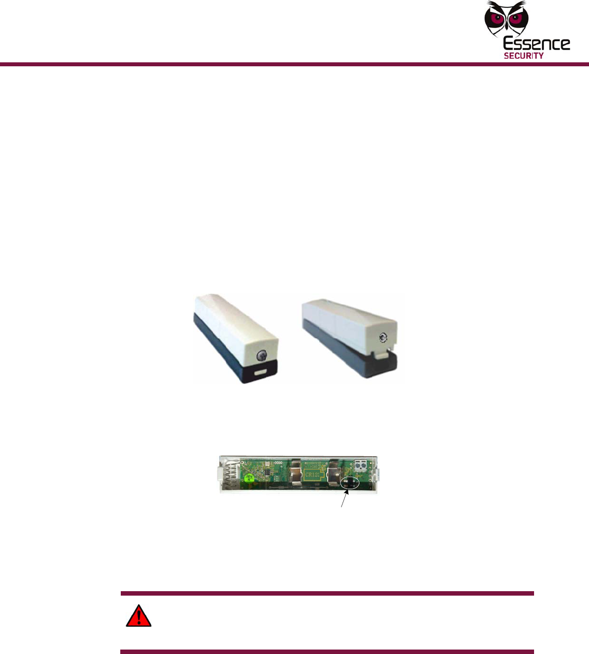
Mainte
n
Multi-Pur
p
6
6.1
n
ance
p
ose Magne
t
Mai
n
Repl
The ES
7
display
e
When t
h
within a
To re
p
1.
I
s
2.
G
p
Figu
r
3.
R
t
p
Figur
T
A
i
W
R
b
4.
R
t
ic Switch
n
tena
acing
7
00MGLS h
e
d via the
d
h
e battery
s
few days.
p
lace a
b
I
f the scre
w
s
crew with
G
ently inse
p
ry off the
c
r
e 41: Scr
e
R
emove th
e
t
amper swi
t
p
olarity is
c
e 42: Loca
t
T
he batter
y
A
fter the b
a
ndicates t
h
W
ARNING
R
eplace th
e
b
y the man
R
eplace th
e
nce
the B
a
a
s a nomi
n
d
evice LED
s
tatus indi
c
b
attery:
w
securing
t
a flathead
rt the scre
w
c
over.
e
wdriver In
s
e
old batte
r
t
ch several
c
orrect.
t
ion of the
y
must be
a
a
ttery is in
s
h
at the dev
i
! A new ba
e
battery o
n
ufacturer.
e
top cover
a
ttery
n
al battery
and report
c
ates that i
t
t
he top co
v
screwdrive
w
driver be
t
s
ertion Poi
n
r
y and trig
g
times, an
d
T
S
ES700MG
L
a
3V CR-12
s
talled, the
ice has be
e
a
ttery can
e
n
ly with th
e
Discard us
e
of the dev
life of 3 ye
a
ed automa
t
t
is low, th
e
v
er to the
m
r.
t
ween the
s
n
t and Top
g
er the ta
m
d
then repl
a
T
amper
S
witch
L
S Device
T
3A Lithium
red LED g
e
n success
f
e
xplode if i
t
e
same or
e
e
d batterie
ice onto th
e
a
rs. The b
a
t
ically to t
h
e
battery s
m
ounting is
s
ide snap a
Cover Sep
m
per mech
a
a
ce the ba
t
T
amper Me
c
battery.
l
ows for 3
s
ully power
e
t
is incorre
c
e
quivalent
t
s
responsi
b
e
bottom c
a
a
ttery stat
u
h
e monitori
hould be r
e
present, r
e
nd the top
aration
a
nism by p
r
t
tery maki
n
c
hanism
s
econds. T
h
e
d up.
c
tly install
e
t
ype reco
m
b
ly.
asing.
2
7
u
s is
ng center.
e
placed
e
move the
cover and
r
essing the
n
g sure the
h
is
d.
m
mended
7

28
App
e
Electri
c
Power
S
Battery
Battery
Wirele
s
Bi-dire
c
Freque
n
RF Cov
e
Encodi
n
Functi
o
Detecti
o
Magnet
Visual I
Tampe
r
Numbe
r
suppor
t
design
a
Enviro
n
Operati
Storag
e
Humidi
t
e
ndix
c
al
S
upply:
Life:
Power Te
s
ss
c
tional:
n
cy:
e
rage:
n
g:
o
nal
o
n Thresh
o
Polarity:
I
ndications
:
r
Mechanis
m
r
of ES700
M
t
ed is depe
a
ted functi
o
n
mental
ng Tempe
r
e
Tempera
t
t
y
A
E
s
t:
o
ld:
:
m
:
M
GLS devi
c
ndent on
o
n:
r
atures:
t
ures:
E
S70
0
One
Ove
r
Upo
n
End
-
Adv
a
BFS
K
(fac
t
700
32-
b
Clos
i
Ope
n
Irrel
e
1 Gr
1 R
e
Dou
b
c
es In E
v
Intr
u
Inp
u
In t
h
Intr
u
Inp
u
-10°
-20°
95
%
0
MGL
S
3V C
R
-12
3
r
3 years (
u
n
power-u
p
-
to-End Bi-
D
a
nced radi
o
K
, 868.3 M
t
ory config
u
meters (2
2
b
it ID, over
ing distanc
n
ing distan
evant
r
een LED f
o
e
d LED for
o
b
le Trigger
e
v
erGuard
a
u
sion Dete
c
u
t Terminal
s
h
e EverGua
u
sion Dete
c
u
t Terminal
s
°
~50° Celsi
°
~60° Celsi
%
non-cond
e
Mu
l
S
Spe
c
3
A Lithium
u
nder nomi
p
and perio
d
D
irectional
o
supervisi
o
H
z in Euro
p
u
red)
2
96 feet) (
O
4 billion c
o
e: 35 mm
ce: 45 m
m
o
r closure
o
pening
e
d Tamper
a
nd EverGu
c
tors, Shoc
s
: 16 devi
c
rd Express
c
tors + Sh
o
s
: 8 device
us (14° -
1
us (-4° - 1
e
nsing
ti-Purpose
M
c
ifica
t
battery
nal conditi
o
d
ically
ESI proto
c
o
n algorith
m
p
e and FM
9
O
pen Air N
o
o
mbination
s
(
~1.38 inc
h
(~1.78 in
c
– cover o
p
a
rd Expres
k
Sensors:
es
system:
o
ck Sensor
s
s
1
22° Fahre
n
40° Fahre
n
Ma
M
agnetic S
w
t
ions
o
ns)
c
ol
m
9
16.5MHz
i
o
minal)
s
h
)
c
h)
p
en & Wall
s-2 syste
m
64 device
s
s
: 32 devic
n
heit)
n
heit)
intenanc
e
itch
i
n US
t
earing
m
s:
s
es
e

Mainte
n
Multi-Pur
p
Physic
a
Dimen
s
Weight
:
Color:
Compl
i
CE:
Radio:
Safety:
Securit
y
Enviro
n
Reliabil
Enviro
n
Manufa
Standa
r
Markin
g
n
ance
p
ose Magne
t
a
l
s
ions:
:
i
ance wit
h
y
and Alar
m
n
mental Re
g
ity (Mecha
n
n
mental co
n
cturing an
d
r
ds:
g
s:
t
ic Switch
h
Standar
d
m
Systems
g
ulation:
n
ical and
n
ditions):
d
Materials
Sma
Per
m
Sma
Per
m
Cov
e
Bas
e
Mag
n
d
s
ETS
I
ETS
I
EN
5
EU
D
ETS
I
ETS
I
CEP
T
EN
5
EN/I
:
EN
5
EN
5
EN5
0
Com
EN
5
IEC
6
ISO
ISO
rt magnet
m
anent ma
g
rt magnet
m
anent ma
g
e
r: RAL 90
0
e
: RAL 703
5
n
et: RAL 9
0
I
EN 301 4
8
I
EN 301 4
8
5
0130-4
D
irective 1
9
I
EN 300 2
2
I
EN 300 2
2
T
/ERC - Re
c
5
0131-5-3
I
EC60950-
1
5
0131-1:2
0
5
0131-2-6:
0
131-6:20
0
m
pliance to
5
0130-5:1
9
6
0068
9001:200
8
14000
sensor– 9
8
g
net – 46
x
sensor – 4
g
net – 25
g
0
3 (Glossy
5
(Silver)
0
03 (Gloss
y
8
9-4
8
9-1
9
99/5/EC f
o
2
0-3
2
0-1
c
ommenda
1
0
06 + A1:2
2008 Clas
s
0
8 Type-C
RoHS: 200
9
98
8
8
x 25 x 25
x
14.5 x 10
5
grams (i
n
g
rams
white)
y
white)
o
r R&TTE
tion 70-3
009 Class-
I
s
-II Grade-
2
2/95/EC
mm (L x
W
0
mm (L x
W
n
cl. batter
y
II Grade-2
2
2
9
W
x H)
W
x H)
y
)
9