Essence Security ES800TR5 Tag reader User Manual We R System
Essence Security International ltd. Tag reader We R System
Contents
- 1. User manual_24733FL_part5
- 2. User manual _24733SK2_part6
- 3. User manual _24733UT_part7
- 4. User manual _24734_part1
- 5. User manual _24734_part2
- 6. User manual _24734_part3
- 7. User manual _24734_part8
- 8. User manual _24734TR5_part4
- 9. User manual_24733SK2_part6
- 10. User manual_24733UT_part7
- 11. User manual_24734_part1
- 12. User manual_24734_part2
- 13. User manual_24734_part3
- 14. User manual_24734_part8
- 15. User manual_24734TR5_part4
User manual_24733FL_part5
Installation of the We.R™ System
146
We.R™ System User Guide
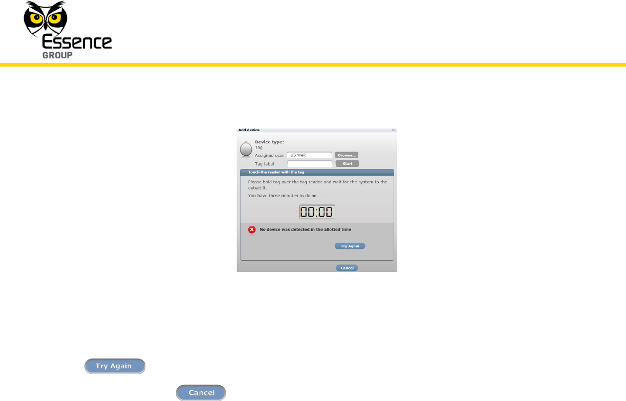
Figure 115: Add New Tag Timeout Error Message
In such a case, it is possible to re-initiate the Add New Device process by clicking over the
button.
Clicking over the button will terminate the Add New Device process.
11. If the new Tag was properly identified by the CCU within this time-frame, the counter will
freeze.
12. You may verify that the Tag was properly added by checking the details of the We.R™ Web
Application’s Devices page.
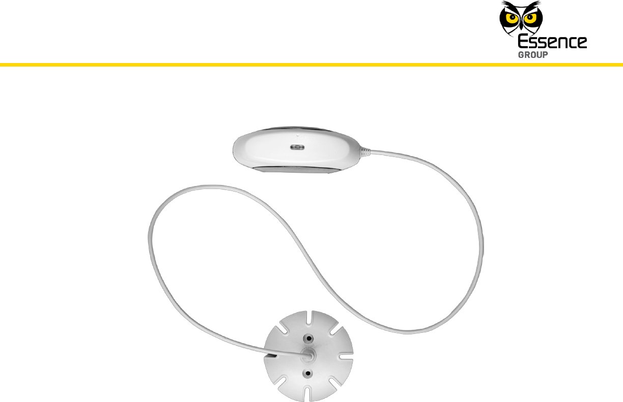
3.11. The Flood Detector (FL) – ES800FL
The Flood Detector (FL) is a We.R™ sensor/detector for early warning of developing floods.
This sensor device consists of two (2) connected elements – a passive Fluid Sensor Unit and a
larger RF Transmitter Unit.
Accessories available for the Flood Detector:
Double-sided adhesive tape on both the Transmitter and the Sensor.
Installation of the We.R™ System
We.R™ System User Guide
147
Figure 116: The Flood Detector
3.11.1. The Flood Detector Function
The Flood Detector incorporates the following functions:
Bi-directional wireless sensor.
Detect developing floods in high‐risk areas such as basements, near air conditioners
and washing machines, sinks and alike.
Dual-LED indication for flood detected (red) and flood diminished (green) status.
Data security is ensured with 128-bit AES encryption.
Up to 500m (1640 feet) RF range (open air) communication.
Unique electronic serial number.
Supports automatic over-the-air software upgrade programming and configuration.

Installation of the We.R™ System
148
We.R™ System User Guide
Tamper Alarm – when the Transmitter unit is ripped off its base.
Provides long operation period while powered by a single standard AA-size Alkaline
battery.
3.11.2. Installing the Flood Detector
The Flood Detector should be mounted near the flood risked area.
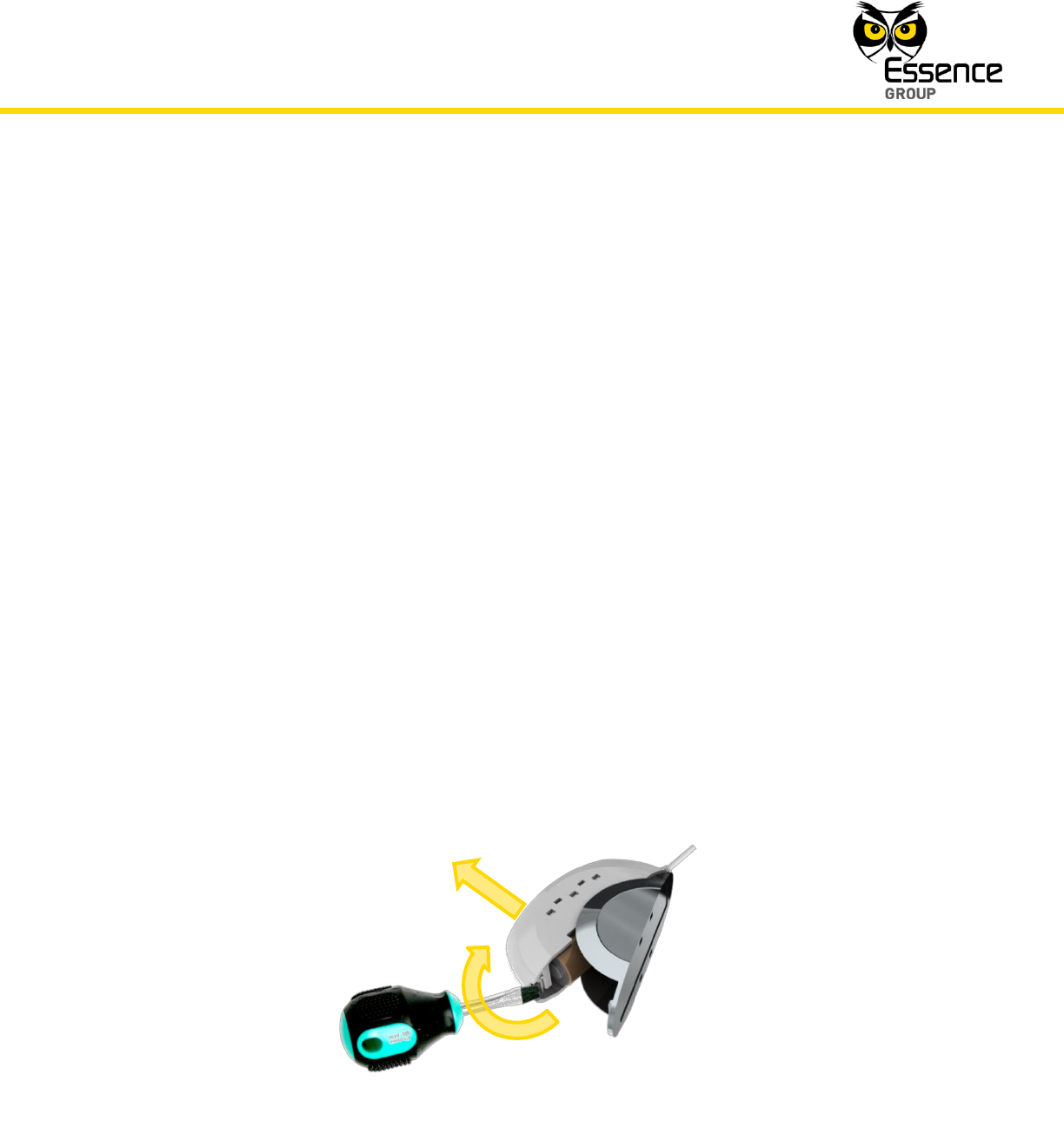
Figure 117: Releasing the Flood Detector Transmitter Base
The Flood Detector Transmitter Unit mounting base is the unit’s back cover (where it also
serves the purpose of battery cover).
The base should be disassembled from the Transmitter Unit body, as demonstrated in Figure
117 above, and attached either by the double-sided tape (pre-attached to the base) or using
screws as demonstrated in Figure 118 below.
The Flood Detector’s Sensor Unit mounts directly utilizing either the double-sided tape (pre-
attached to the Sensor’s bottom) or using screws as demonstrated in Figure 119 below.
Installation of the We.R™ System
We.R™ System User Guide
149
3.11.2.1. Flood Detector Positioning Recommendations
For optimal safety, the following factors must be taken into consideration when selecting the
Flood Detector mounting position:
A flat vertical surface for the transmitter, horizontal for the sensor.
Attach the Flood Detector (applicable for both parts) to a surface that is clean, dry, flat
and smooth.
The Flood Detector must be mounted within 700m (2300ft) (open air nominal) of the
CCU.
Typically, the Transmitter Unit will be attached onto a nearby wall or furniture while the
Sensor Unit is built for installation directly onto the potentially flooded zone.
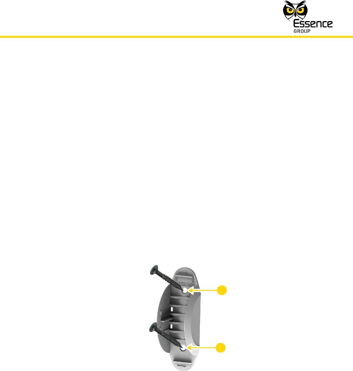
3.11.2.2. Installing the Flood Detector Transmitter Unit with Screws
1. Release the Flood Detector Transmitter Unit base by inserting a coin into one of the edge
slots, as demonstrated in the Figure 117 above, and twist it to open the cover.
2. Use a flat screwdriver to remove the punch-outs 1 and 2 (see Figure 118 below).
Figure 118: Flood Detector Transmitter Unit Base with Screws
2
1
Installation of the We.R™ System
150
We.R™ System User Guide
3. Place and hold the base on the desired mounting location and mark the drilling locations
(the above-mentioned punch-outs 1 and 2).
4. Drill the holes; insert two (2) dowels if needed, place the base over them and screw in the
two (2) screws.
5. Attach the Transmitter Unit onto its base.
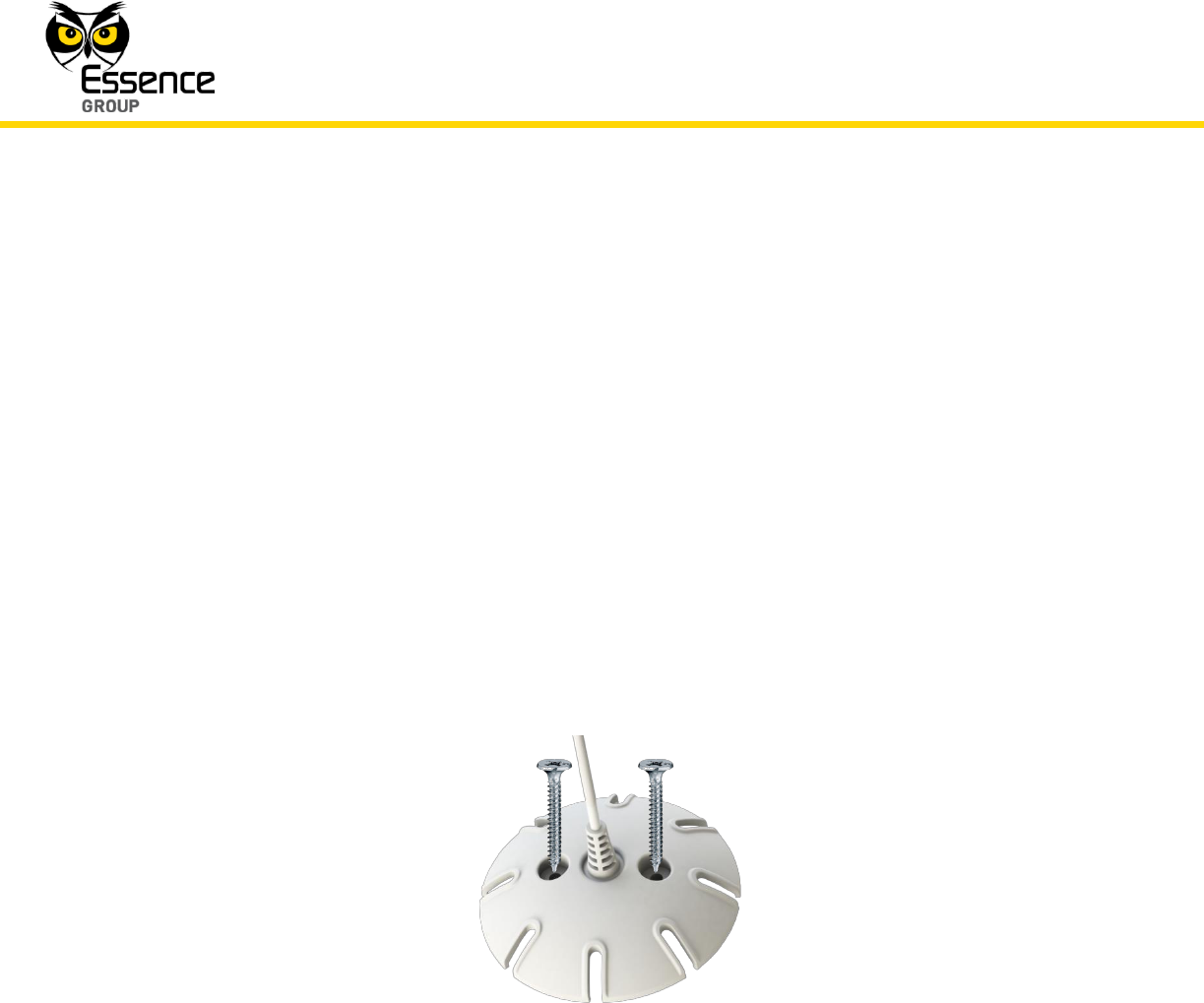
3.11.2.3. Installing the Flood Detector Sensor Unit with Screws
1. Place and hold the Sensor Unit base on the desired mounting location and mark the drilling
locations.
2. Drill the holes; insert two (2) dowels if needed, place the Sensor Unit base over them and
screw in the two (2) screws.
Figure 119: Mounting the Sensor Unit with Screws
3.11.2.4. Installing Transmitter Unit with Pre-attached Double-side Tape
The pre-attached double-sided tape will be mostly utilized for installation of the Transmitter
Unit.
1. Release the Transmitter Unit base (see above Figure 117).
2. Peel the tapes’ protective covers.
Installation of the We.R™ System
We.R™ System User Guide
151
3. Attach the base to its designated location while applying slight pressure.
4. Attach the Transmitter Unit back to its base.
3.11.2.5. Installing Sensor Unit with Pre-attached Double-side Tape
Pre-attached double-sided tape will be mostly utilized for the installation of the Sensor Unit.
1. Peel the tapes’ protective covers.
2. Attach the base to its designated location while applying slight pressure.
3.11.2.6. Dismounting the Flood Detector
For dismounting the Flood Detector (Transmitter unit only) from its designated installation site
(i.e. in case of battery replacement):
1. Insert a coin (or flat screw driver) into one of the edge slots as demonstrated in Figure 120
below.
2. Twist it to raise the cover (body) edge.
3. Pull the body strait out of the base’s shoulders.
Figure 120: Dismounting the Flood Detector Transmitter Unit

Installation of the We.R™ System
152
We.R™ System User Guide
3.11.3. Adding the Flood Detector to the We.R™ System
The Flood Detector need to be functionally added to the system following the above described
physical installation procedure.
The addition of the Flood Detector is a standard Add Device procedure performed as follows:
Note: You may also want to refer to paragraph 5.1 below to get acquainted
with the process of installing/replacing a battery in the Flood Detector.
1. Prepare a single AA-size Alkaline battery required to power the Flood Detector.
2. Activate the We.R™ Web Application.
3. Select the Devices page (tab) and click over the button.
Figure 121: Add Flood Detector Device Utilizing Web Application
Installation of the We.R™ System
We.R™ System User Guide
153
4. A roll-down selection menu will open.
5. Click over the _Add Flood Detector_ option of the menu as illustrated in Figure 121 above:
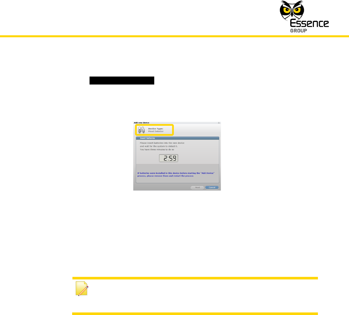
6. An Add New Device (Flood Detector) window will pop-up and its timer will start running.
Figure 122: Add Flood Detector Window
7. Verify that the Device Type is Flood Detector.
8. The down-counter provides a time-frame of three (3) minutes within which the battery
should be installed to power-up the Flood Detector, as demonstrated in Figure 123 below:
Note: In case the installation of the battery could not be accomplished
within the three (3) minutes period, it is possible to restart the process by
applying step 2 (on page 152) and onwards again.
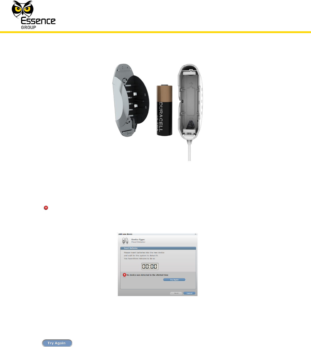
Verify battery polarity to match marking within the unit body.
9. The insertion of battery into the Flood Detector triggers a handshake process in which the
Flood Detector communicates with the CCU to inform it of its presence and the CCU add it
to its peripherals’ inventory.
Installation of the We.R™ System
154
We.R™ System User Guide
Figure 123: Inserting a Battery into the Flood Detector
10. If the CCU did not detect the new Flood Detector within this time-frame, the following error
( ) message will appear within the Add New Device window:
Figure 124: Add New Flood Detector Timeout Error Message
In such a case, it is possible to re-initiate the Add New Device process by clicking over the
button.

Installation of the We.R™ System
We.R™ System User Guide
155
Clicking over the button will terminate the Add New Device process.
13. If the new Flood Detector was properly detected by the CCU within this time-frame, the
counter will freeze and a Device Properties sub-window will appear within the Add New
Device window, where the Flood Detector’s system name/location needs to be typed-in.
Figure 125: Add New Flood Detector Device Properties
Clicking over the button will end the Add New Device process while the new
Flood Detector is added onto the system configuration.
14. You may verify that the Flood Detector (FL) was properly added by checking the details of
the We.R™ Web Application’s Devices page.
3.12. The Smoke Detector (SK2) – ES800SK2
The ES800SK2 is a battery-powered Smoke Detector device designed for installation on
ceilings or walls.
It contains a photoelectric smoke detection chamber and is capable of bi-directional RF (radio
frequency) communication with the We.R™ system Central Control Unit at a remote location.