Essence Security ES800TR5 Tag reader User Manual We R System
Essence Security International ltd. Tag reader We R System
Contents
- 1. User manual_24733FL_part5
- 2. User manual _24733SK2_part6
- 3. User manual _24733UT_part7
- 4. User manual _24734_part1
- 5. User manual _24734_part2
- 6. User manual _24734_part3
- 7. User manual _24734_part8
- 8. User manual _24734TR5_part4
- 9. User manual_24733SK2_part6
- 10. User manual_24733UT_part7
- 11. User manual_24734_part1
- 12. User manual_24734_part2
- 13. User manual_24734_part3
- 14. User manual_24734_part8
- 15. User manual_24734TR5_part4
User manual _24733SK2_part6
Installation of the We.R™ System
156
We.R™ System User Guide
When properly located, installed and maintained, it is designed to give early warning of fires by
producing alarm sounds. It can provide precious time for you and your family to escape before
a fire spreads.
Smoke detection triggers:
A loud piezoelectric buzzer (85 dBA at 3 meters),
Turns-on red LEDs on the device, and
Sends an RF signal to the We.R™ system Central Control Unit.
The Smoke Detector detects smoke that enters its chamber. It does not detect gas, heat or
flame.
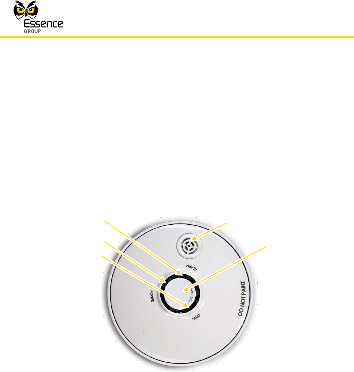
Figure 126: The Smoke Detector Front Panel
Buzzer
LEDs:
Orange
Green
Red
Test/Mute
Button

Installation of the We.R™ System
We.R™ System User Guide
157
WARNING! Never disable the Smoke Detector device and never remove
the batteries to stop a nuisance alarm.
To eliminate the alarm, open a window or use a fan to remove the smoke
around the device. The alarm will turn itself off as soon as the smoke
scatters.
If a nuisance alarms persists, clean the Smoke Detector as described in
paragraph 3.12.2.3 below.
Do not stand close to the Smoke Detector when the alarm is on. The alarm
is very loud in order to wake you up in case of an emergency. Continuous
exposure to the buzzer sound at close range may be harmful to your
hearing.
3.12.1. Product Function
The Smoke Detector incorporates the following functions:
Bi-directional wireless sensor.
The alarm functions even if RF connectivity with the Central Control Unit is lost.
Data security is ensured with 128-bit AES encryption.
Up to 500m (1640 feet) RF range (open air) communication.
Unique electronic serial number.
Supports automatic over-the-air software upgrade programming and configuration.
Tamper Alarm – when the device is ripped off its base.
Special mechanism to prevent installation without batteries.
Three (3) colored LEDs indication for Power (green), Alarm (red) and trouble (amber).
Provides long operation period while powered by two (2) standard AA-size Alkaline
batteries.
Complies with all major electromagnetic compatibility/interference, safety, security,
reliability, and environmental standards for smoke detectors.
Installation of the We.R™ System
158
We.R™ System User Guide
3.12.2. Installing the Smoke Detector
The Smoke Detector is designed for residential zones only. It can be used in a single family
home or in apartment buildings. In multi-family buildings, each apartment needs to install its
own Smoke Detector.
WARNING! Do not use this Smoke Detector device in non-residential
buildings. Warehouses, industrial buildings, commercial buildings, etc.,
require special fire detection and alarm systems.
This device is not a substitute for a complete fire detection system for sites
where many people live or work (i.e. hotels, motels, dormitories, hospitals,
nursing homes and group homes) even if they once were single family
homes.
See NFPA (National Fire Protection Association) standard 101 (Life Safety
Code) and NFPA standard 72 (Fire Alarm and Signaling Code) for fire alarm
requirements.
3.12.2.1. Smoke Detector Positioning Recommendations
For complete coverage in residential units, Smoke Detectors should be installed in all
rooms, halls, storage areas, basements, and attics.
WARNING! Smoke Detectors installed in common areas such as porches
or outside hallways may not provide sufficient early warning for residents.
For minimum coverage install one alarm on each floor and one in each bedroom zone.
Smoke Detectors should be installed in accordance with the NFPA (National Fire
Protection Association) standard 72.
For optimal detection, consider these factors when selecting a mounting position:
Installation of the We.R™ System
We.R™ System User Guide
159
The Smoke Detector should be mounted on the ceiling but may also be
mounted on a wall.
The Smoke Detector must be installed within 500m (1640 feet) of the Central
Control Unit.
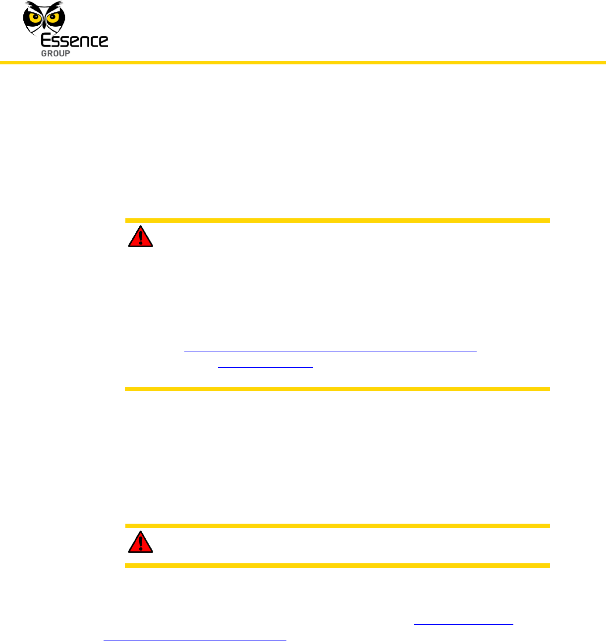
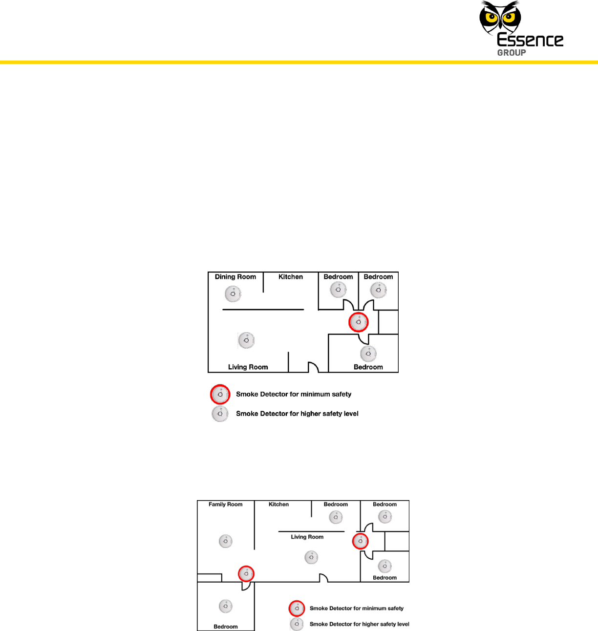
Install the Smoke Detector in the hallway, close but outside every separated
bedroom area, as shown in Figure 127 below. Two alarms are required in
homes with two bedroom areas, as shown in Figure 128 below.
Figure 127: Smoke Detectors in Single Bedroom Area
Figure 128: Smoke Detectors in Multiple Bedroom Areas

Installation of the We.R™ System
160
We.R™ System User Guide
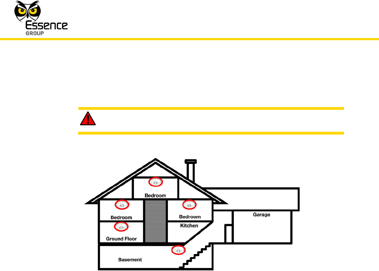
Install a Smoke Detector on every floor of a multi-floor house as shown in
Figure 129 below.
WARNING! Make sure doors or other barriers do not block the path of
smoke to the Smoke Detectors.
Figure 129: Smoke Detectors in Multi-floor House
Install Smoke Detectors at both ends of a bedroom hallway if the hallway is
longer than 12 meters (40 feet).
Install basement Smoke Detectors at the bottom of the stairway as shown in
Figure 129 above.
Install the Smoke Detectors as close to the center of the ceiling as possible. If
this is not practical, install the Smoke Detector on the ceiling no less than 10
cm (4 inches) away from any wall or corner.
If ceiling mounting is not possible and wall mounting is allowed by your local
and state codes, mount the Smoke Detectors on a wall 10 to 15 cm (4 to 6
inches) from the ceiling.

Installation of the We.R™ System
We.R™ System User Guide
161
In rooms with sloped, peaked, or gabled ceilings, mount the Smoke
Detectors 90 cm (3 feet) measured horizontally from the highest point of the
ceiling.
Nuisance alarms occur if Smoke Detectors are installed where they do not
work properly. To avoid nuisance alarms, do not install alarms in the following
locations:
a) Areas where combustion particles are present (i.e. kitchens with few
windows or poor ventilation, garages where there may be vehicle
exhaust), or near heaters, hot water boilers, etc.
b) Less than 6 meters (20 feet) from places where combustion particles are
present. If such distance is not available (e.g., in mobile homes), install
the alarm as far away from the combustion particles as possible,
preferably on the wall. Provide good ventilation in such places.
c) Damp or humid areas. Moisture can enter the detection chamber. Upon
cooling, the developed water drops may cause nuisance alarms. Install
Smoke Detectors at least 3 meters (10 feet) away from bathrooms.
d) Very cold or very hot areas, including unheated buildings and outdoor
rooms. If the temperature goes above or below the operating range of
the Smoke Detector, the device will not work properly.
e) Very dusty or dirty areas. Dirt and dust can build up in the Smoke
Detector’s chamber, making it over-sensitive. In addition, dust or dirt
can block openings to the chamber and keep the Smoke Detector from
sensing smoke.
f) Drafty areas and areas near fresh air vents, air conditioners, heaters or
fans. These can drive smoke away from smoke alarms.
g) Dead air spaces near the top of a peaked roof or in the corners formed
by ceilings and walls. Dead air can prevent smoke from reaching the
Smoke Detector.
h) In insect-infested areas. If insects enter the Smoke Detector’s chamber,
they may cause a nuisance alarm.
Installation of the We.R™ System
162
We.R™ System User Guide
i) Near fluorescent lights. Electrical discharges from fluorescent lights can
cause nuisance alarms. Install Smoke Detectors at least 1.5 meters (5
feet) from such lights.
WARNING! To prevent injury, the Smoke Detector must be securely
attached to the wall/ceiling in accordance with the following instruction.
3.12.2.2. Installing Smoke Detector with Screws
Mounting the Smoke Detector with screws requires the following tools and materials:
A drill with a standard 5 mm (3/16-inch) bit.
Standard Phillips screwdriver.
Two DIN 7982 Philips cross recessed flat countersunk head screws (3.5 x 16 mm) and,
pending material of installation site, two plastic, series 108 dowels, with drill hole
diameter of 5 mm (3/16-inch) and length of 25 mm (1-inch).
Note: The Smoke Detector base include four (4) holes for screws for
flexibility of installation. Only two (2) screws are necessary for a secure
installation.
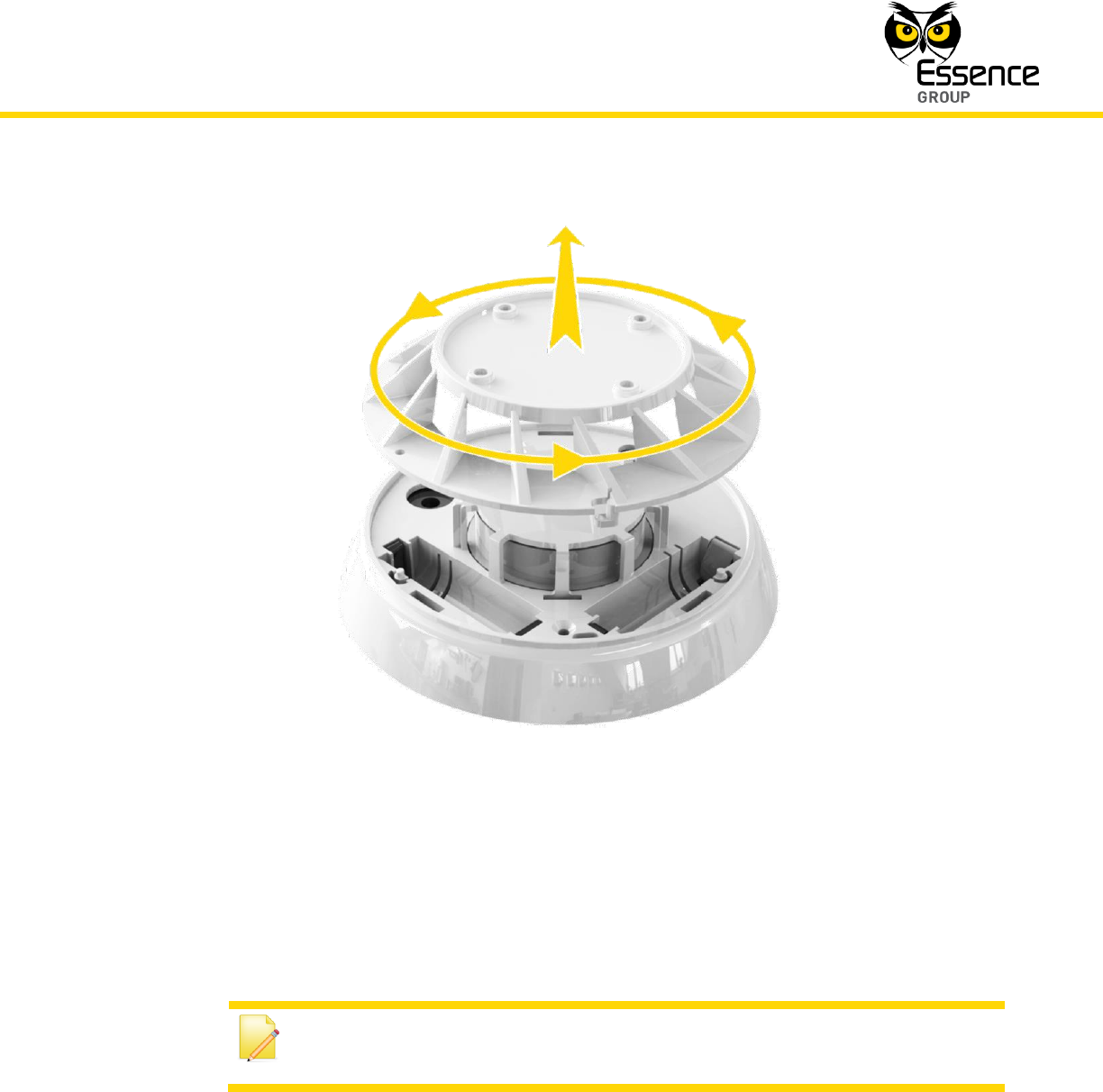
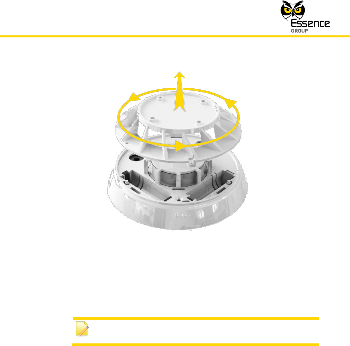
1. Remove the mounting bracket (base of the Smoke Detector) from the device by turning it
counter-clockwise as demonstrated in Figure 130 below.
Installation of the We.R™ System
We.R™ System User Guide
163
Figure 130: Disassembling the Mounting Bracket of the Smoke Detector
2. Place the Bracket in the installation position. Mark each keyhole slot.
3. Remove the Bracket and use a 5 mm (3/16-inch) drill bit to drill a hole at each of the three
marks.
Note: Prevent dust from getting into the Smoke Detector while drilling the
holes!
4. Insert the plastic dowels, if needed, into the drilled holes.
5. Attach the Bracket onto the ceiling (or wall) using the two screws.
Installation of the We.R™ System
164
We.R™ System User Guide
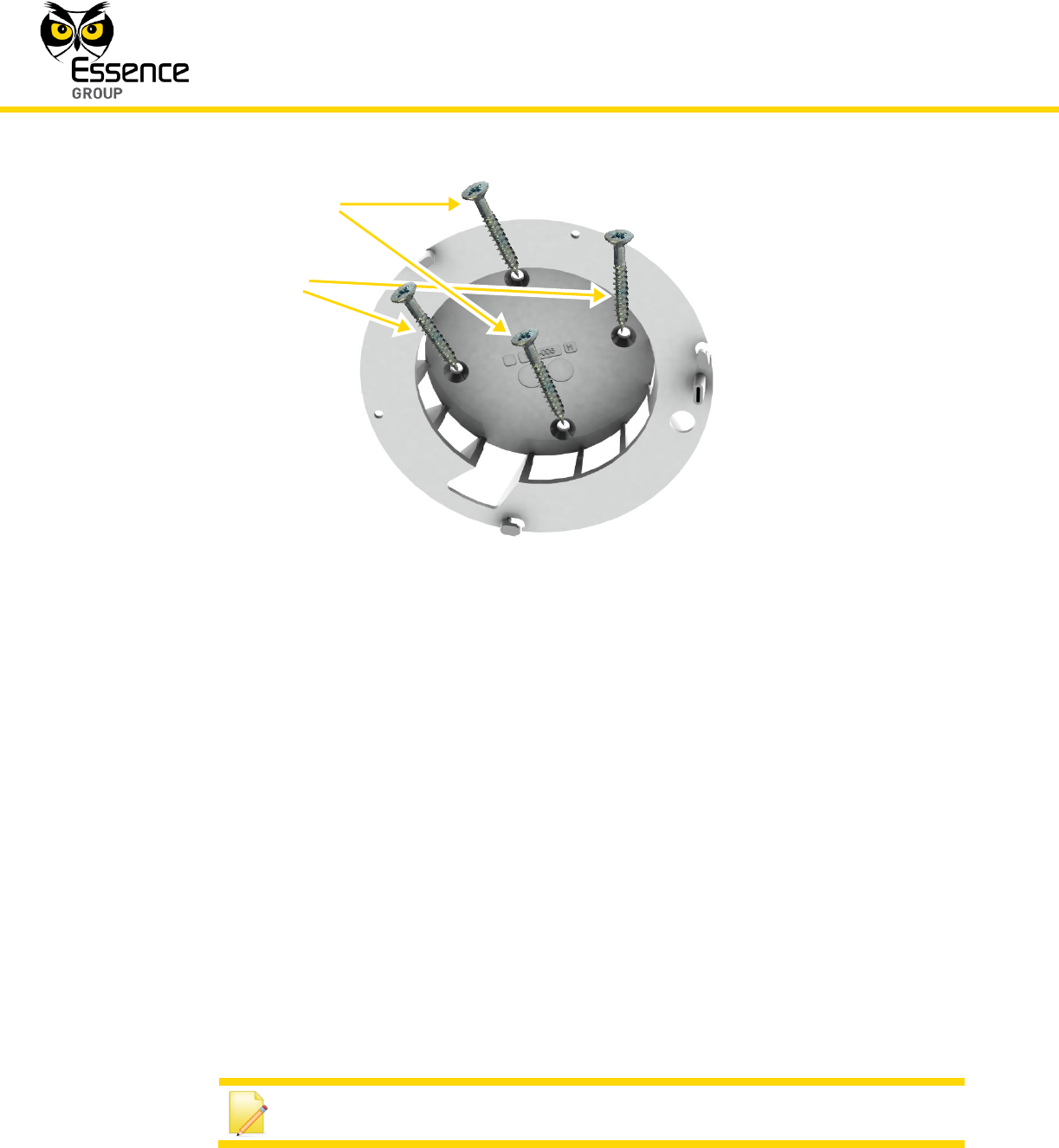
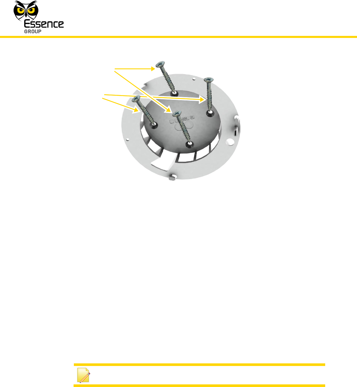
Figure 131: Screw Positions for Mounting the Bracket of the Smoke Detector
The Smoke Detector is now ready for power-up and addition onto the We.R™ system.
3.12.2.3. Cleaning the Smoke Detector
Following the installation and prior to the power-up of the Smoke Detector, or, on a regular
basis as detailed below, it is advised to clean the Smoke Detector.
The Smoke Detector is designed to be as maintenance-free as possible. To keep the Smoke
Detector in good working condition, there is a need to test the device once a month and clean
it once a year.
To clean the Smoke Detector, dismount it from the bracket, remove the batteries, and vacuum
the dust out of the detection chamber. Use the soft brush of the vacuum cleaner to remove
dust and dirt from the detection chamber.
Note: Do not use water or detergents since they can damage the device.
Install with either this set
of screws…
or this set of screws
Installation of the We.R™ System
We.R™ System User Guide
165
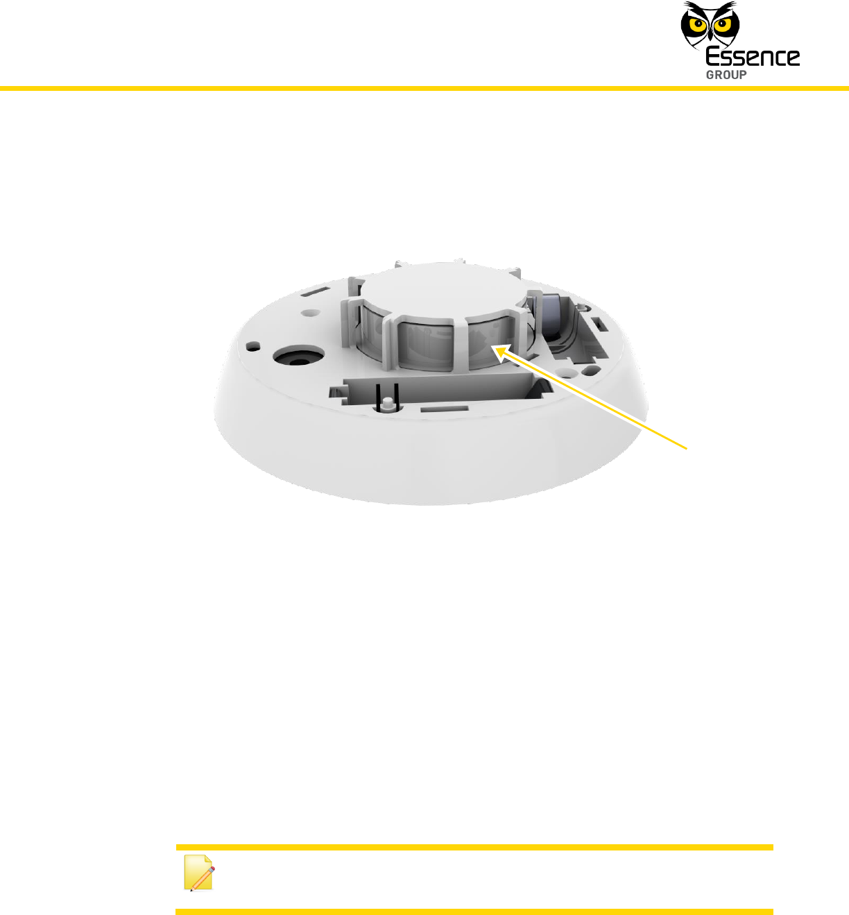
Carefully remove any dust residing on the Smoke Detector's components applying special
attention to the openings of the detection chamber.
Figure 132: Cleaning the Smoke Detector
After cleaning, replace the batteries, and then test the smoke alarm, by pressing the Test/Mute
button, to make sure it is functioning properly.
3.12.3. Adding the Smoke Detector to the We.R™ System
The Smoke Detector need to be functionally added to the system following the above
described physical installation procedure.
The addition of the Smoke Detector is a standard Add Device procedure performed as follows:
Note: You may also want to refer to paragraph 5.1 below to get acquainted
with the process of installing/replacing batteries in the Smoke Detector.
Clean
here

Installation of the We.R™ System
166
We.R™ System User Guide
1. Prepare two (2) AA-size Alkaline batteries required to power the Smoke Detector.
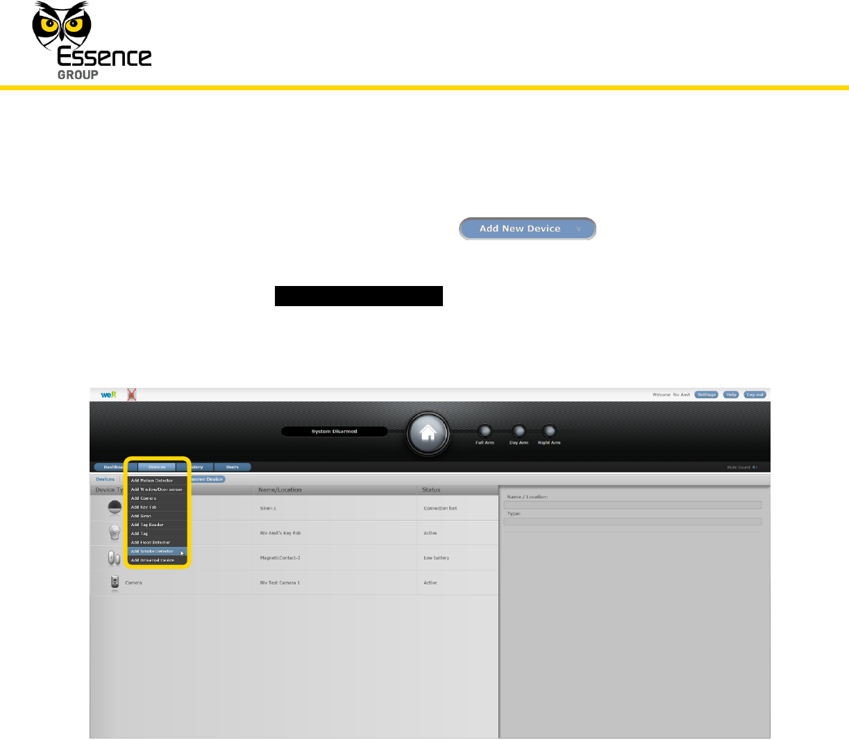
2. Activate the We.R™ Web Application.
3. Select the Devices page (tab) and click over the button.
4. A roll-down selection menu will open.
5. Click over the menu’s _Add Smoke Detector_ option of the menu as illustrated in Figure
133 below:
Figure 133: Add Smoke Detector Device Utilizing Web Application
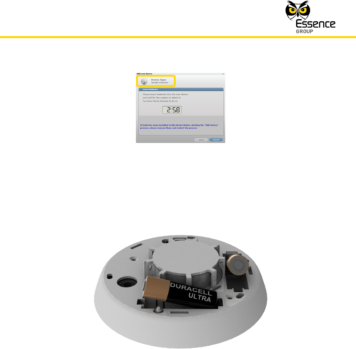
An Add New Device (Smoke Detector) window will pop-up and its timer will start running.
6. Verify that the Device Type is Smoke Detector.
Installation of the We.R™ System
We.R™ System User Guide
167
Figure 134: Add Smoke Detector Window
7. The down-counter provides a time-frame of three (3) minutes within which the two batteries
should be installed to power-up the Smoke Detector, as demonstrated in Figure 135
below:
Figure 135: Inserting a Batteries into the Smoke Detector
Verify batteries’ polarity to match marking within the batteries’ cavities.
Installation of the We.R™ System
168
We.R™ System User Guide
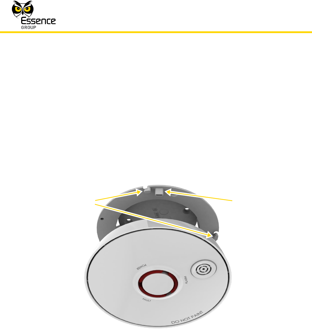
8. Insert the Smoke Detector body into the previously installed Mounting Bracket.
This step of the installation must be very carefully done as the mechanical connection
between these two parts (the Mounting Bracket and the Smoke Detector’s body) was
specially designed to:
Prevent insertion of the Smoke Detector body without the batteries installed
properly.
Provide omni-directional assembly (note the enforcing key in Figure 136
below).
Ensure secured assembly by three (3) locking pins (note marked keys in
Figure 136 below).
Provide the mechanism for tamper prevention.
Figure 136: Omni-directional Assembly of the Smoke Detector
Omni-directional
enforcing key
Locking
pins (two
of three)
Installation of the We.R™ System
We.R™ System User Guide
169
9. Line-up the locking pins and the direction enforcement pin, push the Smoke Detector’s
body into the Mounting Bracket and turn it clockwise until it clicks and locks into position.
10. Confirm proper locking by pulling the body slightly out of the Mounting Bracket.
Note: In case the installation of the batteries could not be accomplished
within the three (3) minutes period, it is possible to restart the process by
applying step 2 (on page 166) and onwards again.
11. The insertion of batteries into the Smoke Detector triggers a handshake process in which
the Smoke Detector communicates with the CCU to inform it of its presence and the CCU
add it to its peripherals’ inventory.
Note: When the batteries make the initial contact with the Smoke Detector
electronic circuit, the tamper prevention sub-system might sound. This
means that the Smoke Detector is working properly and indicated that the
batteries are installed correctly.
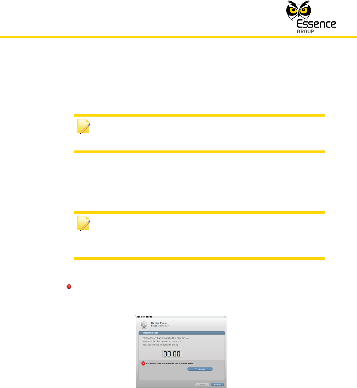
12. If the CCU did not detect the new Smoke Detector within this time-frame, the following
error ( ) message will appear within the Add New Device window:
Figure 137: Add New Smoke Detector Timeout Error Message
Installation of the We.R™ System
170
We.R™ System User Guide
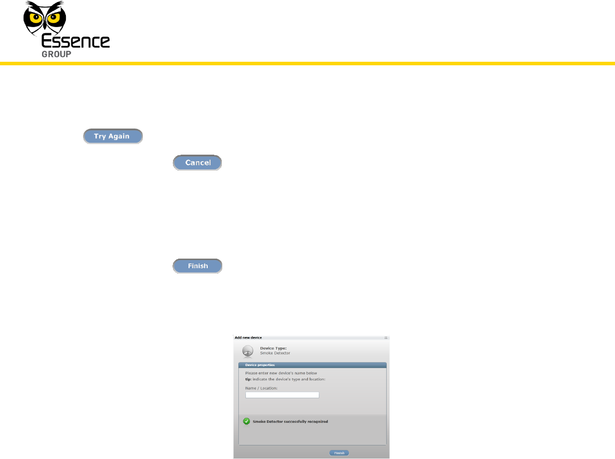
In such a case, it is possible to re-initiate the Add New Device process by clicking over the
button.
Clicking over the button will terminate the Add New Device process.
13. If the new Smoke Detector was properly detected by the CCU within this time-frame, the
counter will freeze and a Device Properties sub-window will appear within the Add New
Device window, where the Smoke Detector’s system name/location needs to be typed-in.
Clicking over the button will end the Add New Device process while the new
Smoke Detector is added onto the system configuration.
Figure 138: Add New Smoke Detector Device Properties
14. You may verify that the Smoke Detector (SK2) was properly added by checking the details
of the We.R™ Web Application’s Devices page.
3.12.3.1. Testing the Smoke Detector
Perform a test, following the mechanical installation of the Smoke Detector, by pressing the
Test/Mute button (center of the front panel) firmly for about 3 seconds until the buzzer sounds
and all three (3) LEDs blink.
The buzzer will produce a loud, pulsating alarm if the unit is working properly.
User manual_24733SK2_part6

Installation of the We.R™ System
156
We.R™ System User Guide
When properly located, installed and maintained, it is designed to give early warning of fires by
producing alarm sounds. It can provide precious time for you and your family to escape before
a fire spreads.
Smoke detection triggers:
A loud piezoelectric buzzer (85 dBA at 3 meters),
Turns-on red LEDs on the device, and
Sends an RF signal to the We.R™ system Central Control Unit.
The Smoke Detector detects smoke that enters its chamber. It does not detect gas, heat or
flame.
Figure 126: The Smoke Detector Front Panel
Buzzer
LEDs:
Orange
Green
Red
Test/Mute
Button

Installation of the We.R™ System
We.R™ System User Guide
157
WARNING! Never disable the Smoke Detector device and never remove
the batteries to stop a nuisance alarm.
To eliminate the alarm, open a window or use a fan to remove the smoke
around the device. The alarm will turn itself off as soon as the smoke
scatters.
If a nuisance alarms persists, clean the Smoke Detector as described in
paragraph 3.12.2.3 below.
Do not stand close to the Smoke Detector when the alarm is on. The alarm
is very loud in order to wake you up in case of an emergency. Continuous
exposure to the buzzer sound at close range may be harmful to your
hearing.
3.12.1. Product Function
The Smoke Detector incorporates the following functions:
Bi-directional wireless sensor.
The alarm functions even if RF connectivity with the Central Control Unit is lost.
Data security is ensured with 128-bit AES encryption.
Up to 500m (1640 feet) RF range (open air) communication.
Unique electronic serial number.
Supports automatic over-the-air software upgrade programming and configuration.
Tamper Alarm – when the device is ripped off its base.
Special mechanism to prevent installation without batteries.
Three (3) colored LEDs indication for Power (green), Alarm (red) and trouble (amber).
Provides long operation period while powered by two (2) standard AA-size Alkaline
batteries.
Complies with all major electromagnetic compatibility/interference, safety, security,
reliability, and environmental standards for smoke detectors.
Installation of the We.R™ System
158
We.R™ System User Guide
3.12.2. Installing the Smoke Detector
The Smoke Detector is designed for residential zones only. It can be used in a single family
home or in apartment buildings. In multi-family buildings, each apartment needs to install its
own Smoke Detector.
WARNING! Do not use this Smoke Detector device in non-residential
buildings. Warehouses, industrial buildings, commercial buildings, etc.,
require special fire detection and alarm systems.
This device is not a substitute for a complete fire detection system for sites
where many people live or work (i.e. hotels, motels, dormitories, hospitals,
nursing homes and group homes) even if they once were single family
homes.
See NFPA (National Fire Protection Association) standard 101 (Life Safety
Code) and NFPA standard 72 (Fire Alarm and Signaling Code) for fire alarm
requirements.
3.12.2.1. Smoke Detector Positioning Recommendations
For complete coverage in residential units, Smoke Detectors should be installed in all
rooms, halls, storage areas, basements, and attics.
WARNING! Smoke Detectors installed in common areas such as porches
or outside hallways may not provide sufficient early warning for residents.
For minimum coverage install one alarm on each floor and one in each bedroom zone.
Smoke Detectors should be installed in accordance with the NFPA (National Fire
Protection Association) standard 72.
For optimal detection, consider these factors when selecting a mounting position:
Installation of the We.R™ System
We.R™ System User Guide
159
The Smoke Detector should be mounted on the ceiling but may also be
mounted on a wall.
The Smoke Detector must be installed within 500m (1640 feet) of the Central
Control Unit.
Install the Smoke Detector in the hallway, close but outside every separated
bedroom area, as shown in Figure 127 below. Two alarms are required in
homes with two bedroom areas, as shown in Figure 128 below.
Figure 127: Smoke Detectors in Single Bedroom Area
Figure 128: Smoke Detectors in Multiple Bedroom Areas
Installation of the We.R™ System
160
We.R™ System User Guide
Install a Smoke Detector on every floor of a multi-floor house as shown in
Figure 129 below.
WARNING! Make sure doors or other barriers do not block the path of
smoke to the Smoke Detectors.
Figure 129: Smoke Detectors in Multi-floor House
Install Smoke Detectors at both ends of a bedroom hallway if the hallway is
longer than 12 meters (40 feet).
Install basement Smoke Detectors at the bottom of the stairway as shown in
Figure 129 above.
Install the Smoke Detectors as close to the center of the ceiling as possible. If
this is not practical, install the Smoke Detector on the ceiling no less than 10
cm (4 inches) away from any wall or corner.
If ceiling mounting is not possible and wall mounting is allowed by your local
and state codes, mount the Smoke Detectors on a wall 10 to 15 cm (4 to 6
inches) from the ceiling.

Installation of the We.R™ System
We.R™ System User Guide
161
In rooms with sloped, peaked, or gabled ceilings, mount the Smoke
Detectors 90 cm (3 feet) measured horizontally from the highest point of the
ceiling.
Nuisance alarms occur if Smoke Detectors are installed where they do not
work properly. To avoid nuisance alarms, do not install alarms in the following
locations:
a) Areas where combustion particles are present (i.e. kitchens with few
windows or poor ventilation, garages where there may be vehicle
exhaust), or near heaters, hot water boilers, etc.
b) Less than 6 meters (20 feet) from places where combustion particles are
present. If such distance is not available (e.g., in mobile homes), install
the alarm as far away from the combustion particles as possible,
preferably on the wall. Provide good ventilation in such places.
c) Damp or humid areas. Moisture can enter the detection chamber. Upon
cooling, the developed water drops may cause nuisance alarms. Install
Smoke Detectors at least 3 meters (10 feet) away from bathrooms.
d) Very cold or very hot areas, including unheated buildings and outdoor
rooms. If the temperature goes above or below the operating range of
the Smoke Detector, the device will not work properly.
e) Very dusty or dirty areas. Dirt and dust can build up in the Smoke
Detector’s chamber, making it over-sensitive. In addition, dust or dirt
can block openings to the chamber and keep the Smoke Detector from
sensing smoke.
f) Drafty areas and areas near fresh air vents, air conditioners, heaters or
fans. These can drive smoke away from smoke alarms.
g) Dead air spaces near the top of a peaked roof or in the corners formed
by ceilings and walls. Dead air can prevent smoke from reaching the
Smoke Detector.
h) In insect-infested areas. If insects enter the Smoke Detector’s chamber,
they may cause a nuisance alarm.

Installation of the We.R™ System
162
We.R™ System User Guide
i) Near fluorescent lights. Electrical discharges from fluorescent lights can
cause nuisance alarms. Install Smoke Detectors at least 1.5 meters (5
feet) from such lights.
WARNING! To prevent injury, the Smoke Detector must be securely
attached to the wall/ceiling in accordance with the following instruction.
3.12.2.2. Installing Smoke Detector with Screws
Mounting the Smoke Detector with screws requires the following tools and materials:
A drill with a standard 5 mm (3/16-inch) bit.
Standard Phillips screwdriver.
Two DIN 7982 Philips cross recessed flat countersunk head screws (3.5 x 16 mm) and,
pending material of installation site, two plastic, series 108 dowels, with drill hole
diameter of 5 mm (3/16-inch) and length of 25 mm (1-inch).
Note: The Smoke Detector base include four (4) holes for screws for
flexibility of installation. Only two (2) screws are necessary for a secure
installation.
1. Remove the mounting bracket (base of the Smoke Detector) from the device by turning it
counter-clockwise as demonstrated in Figure 130 below.
Installation of the We.R™ System
We.R™ System User Guide
163
Figure 130: Disassembling the Mounting Bracket of the Smoke Detector
2. Place the Bracket in the installation position. Mark each keyhole slot.
3. Remove the Bracket and use a 5 mm (3/16-inch) drill bit to drill a hole at each of the three
marks.
Note: Prevent dust from getting into the Smoke Detector while drilling the
holes!
4. Insert the plastic dowels, if needed, into the drilled holes.
5. Attach the Bracket onto the ceiling (or wall) using the two screws.
Installation of the We.R™ System
164
We.R™ System User Guide
Figure 131: Screw Positions for Mounting the Bracket of the Smoke Detector
The Smoke Detector is now ready for power-up and addition onto the We.R™ system.
3.12.2.3. Cleaning the Smoke Detector
Following the installation and prior to the power-up of the Smoke Detector, or, on a regular
basis as detailed below, it is advised to clean the Smoke Detector.
The Smoke Detector is designed to be as maintenance-free as possible. To keep the Smoke
Detector in good working condition, there is a need to test the device once a month and clean
it once a year.
To clean the Smoke Detector, dismount it from the bracket, remove the batteries, and vacuum
the dust out of the detection chamber. Use the soft brush of the vacuum cleaner to remove
dust and dirt from the detection chamber.
Note: Do not use water or detergents since they can damage the device.
Install with either this set
of screws…
or this set of screws

Installation of the We.R™ System
We.R™ System User Guide
165
Carefully remove any dust residing on the Smoke Detector's components applying special
attention to the openings of the detection chamber.
Figure 132: Cleaning the Smoke Detector
After cleaning, replace the batteries, and then test the smoke alarm, by pressing the Test/Mute
button, to make sure it is functioning properly.
3.12.3. Adding the Smoke Detector to the We.R™ System
The Smoke Detector need to be functionally added to the system following the above
described physical installation procedure.
The addition of the Smoke Detector is a standard Add Device procedure performed as follows:
Note: You may also want to refer to paragraph 5.1 below to get acquainted
with the process of installing/replacing batteries in the Smoke Detector.
Clean
here
Installation of the We.R™ System
166
We.R™ System User Guide
1. Prepare two (2) AA-size Alkaline batteries required to power the Smoke Detector.
2. Activate the We.R™ Web Application.
3. Select the Devices page (tab) and click over the button.
4. A roll-down selection menu will open.
5. Click over the menu’s _Add Smoke Detector_ option of the menu as illustrated in Figure
133 below:
Figure 133: Add Smoke Detector Device Utilizing Web Application
An Add New Device (Smoke Detector) window will pop-up and its timer will start running.
6. Verify that the Device Type is Smoke Detector.

Installation of the We.R™ System
We.R™ System User Guide
167
Figure 134: Add Smoke Detector Window
7. The down-counter provides a time-frame of three (3) minutes within which the two batteries
should be installed to power-up the Smoke Detector, as demonstrated in Figure 135
below:
Figure 135: Inserting a Batteries into the Smoke Detector
Verify batteries’ polarity to match marking within the batteries’ cavities.

Installation of the We.R™ System
168
We.R™ System User Guide
8. Insert the Smoke Detector body into the previously installed Mounting Bracket.
This step of the installation must be very carefully done as the mechanical connection
between these two parts (the Mounting Bracket and the Smoke Detector’s body) was
specially designed to:
Prevent insertion of the Smoke Detector body without the batteries installed
properly.
Provide omni-directional assembly (note the enforcing key in Figure 136
below).
Ensure secured assembly by three (3) locking pins (note marked keys in
Figure 136 below).
Provide the mechanism for tamper prevention.
Figure 136: Omni-directional Assembly of the Smoke Detector
Omni-directional
enforcing key
Locking
pins (two
of three)

Installation of the We.R™ System
We.R™ System User Guide
169
9. Line-up the locking pins and the direction enforcement pin, push the Smoke Detector’s
body into the Mounting Bracket and turn it clockwise until it clicks and locks into position.
10. Confirm proper locking by pulling the body slightly out of the Mounting Bracket.
Note: In case the installation of the batteries could not be accomplished
within the three (3) minutes period, it is possible to restart the process by
applying step 2 (on page 166) and onwards again.
11. The insertion of batteries into the Smoke Detector triggers a handshake process in which
the Smoke Detector communicates with the CCU to inform it of its presence and the CCU
add it to its peripherals’ inventory.
Note: When the batteries make the initial contact with the Smoke Detector
electronic circuit, the tamper prevention sub-system might sound. This
means that the Smoke Detector is working properly and indicated that the
batteries are installed correctly.
12. If the CCU did not detect the new Smoke Detector within this time-frame, the following
error ( ) message will appear within the Add New Device window:
Figure 137: Add New Smoke Detector Timeout Error Message

Installation of the We.R™ System
170
We.R™ System User Guide
In such a case, it is possible to re-initiate the Add New Device process by clicking over the
button.
Clicking over the button will terminate the Add New Device process.
13. If the new Smoke Detector was properly detected by the CCU within this time-frame, the
counter will freeze and a Device Properties sub-window will appear within the Add New
Device window, where the Smoke Detector’s system name/location needs to be typed-in.
Clicking over the button will end the Add New Device process while the new
Smoke Detector is added onto the system configuration.
Figure 138: Add New Smoke Detector Device Properties
14. You may verify that the Smoke Detector (SK2) was properly added by checking the details
of the We.R™ Web Application’s Devices page.
3.12.3.1. Testing the Smoke Detector
Perform a test, following the mechanical installation of the Smoke Detector, by pressing the
Test/Mute button (center of the front panel) firmly for about 3 seconds until the buzzer sounds
and all three (3) LEDs blink.
The buzzer will produce a loud, pulsating alarm if the unit is working properly.