Etung Technology MD-309 Wireless Data Terminal User Manual MD 309
Etung Technology Co., Ltd Wireless Data Terminal MD 309
UserManual.wiki
>
Etung Technology
>
MD 309 User Manual
User Manual
Navigation menu
Upload a User Manual
Namespaces
Wiki Guide
HTML
PDF
Info
Views
User Manual
Discussion / Help
Navigation

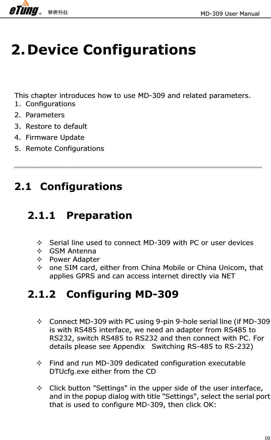
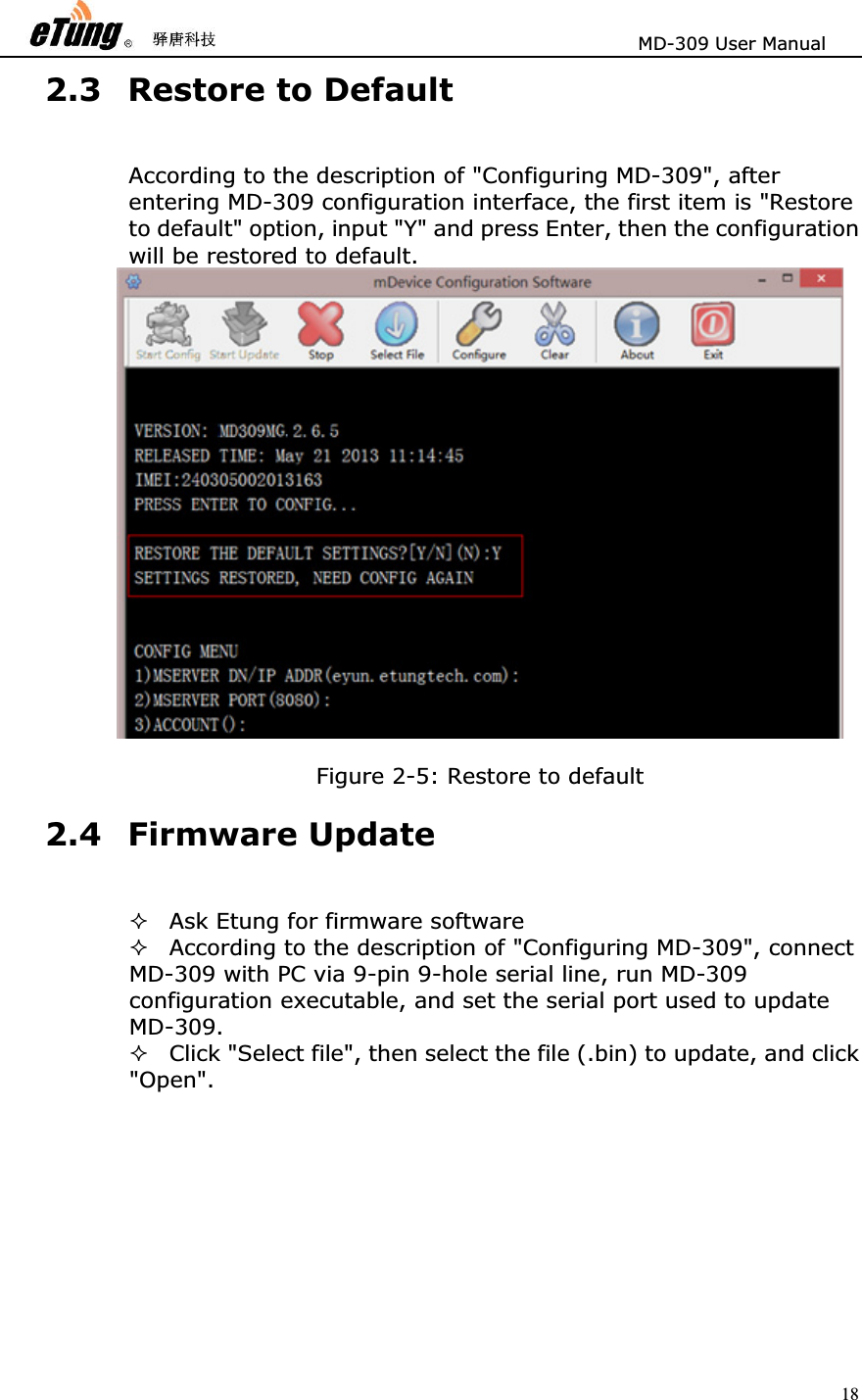
![MD-309 User Manual 13Figure 2-4: Configuration complete 2.2 Configuration Parameters Each configuration menu item of MD-309 includes the following items (those with * are mandatory), details are in the following: *Order number: includes digit and right bracket, for example "10)" *Name and unit: name of the configuration item (some items have unit) Optional values: the contents within "[]" are the values that are allowed in this configuration item, multiple optional values are separated with "/" *Default value: i.e. the content within "()", If you press Enter to skip this item configuration, the default value will be used. Attention: In reality, MD -309 connects user devices via serial port, so serial p ort attributes need to be configured in order to match user device serial port.](https://usermanual.wiki/Etung-Technology/MD-309/User-Guide-2689454-Page-13.png)
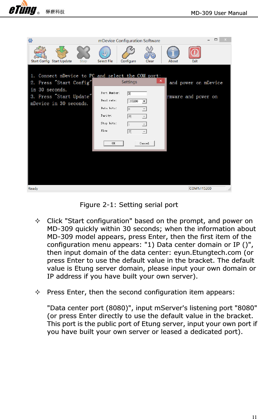
![MD-309 User Manual 14For example: 15) digit bit [5/6/7/8] (8) Order number Name and unit Optional values Default valueBelow are the configuration items with MD-309 V2.8.5. Different versions may have different configuration items. Configuration Menu Item Description RESTORE THE DEFAULT SETTINGS?[Y/N](N) Configure to restore to default or not1) MSERVER DN/ IP ADDR (eyun.Etungtech.com) Configure data center IP address or domain 2) MSERVER PORT (8080) Configure data center port 3) ACCOUNT (Etung) Configure applied eYun username, it is only required to configure if chuankoutong eYun version is used.4) APN name () Configure wireless APN name, normally it is not needed, and default value is used, but users with dedicated network adapter need to configure this item. 5) Network Protocol[UDP/TCP](TCP) Configure data transport protocol, either UDP or TCP. 6) Connect mServer[Y/N](Y) Configure whether to connect mServer, Y by default to connect mServer. 7) Self-define registration packagewhen no mServer connection () When the device does not connectmServer, self-define registrationpackage.8) Self-define heart-beat packagewhen no mServer connection () When the device does not connectmServer, self-define heart-beatpackage.9) Serial port output connectioninformation[Y/N](N) Configure whether to outputconnection information from serialport, N by default, i.e. do not output](https://usermanual.wiki/Etung-Technology/MD-309/User-Guide-2689454-Page-14.png)
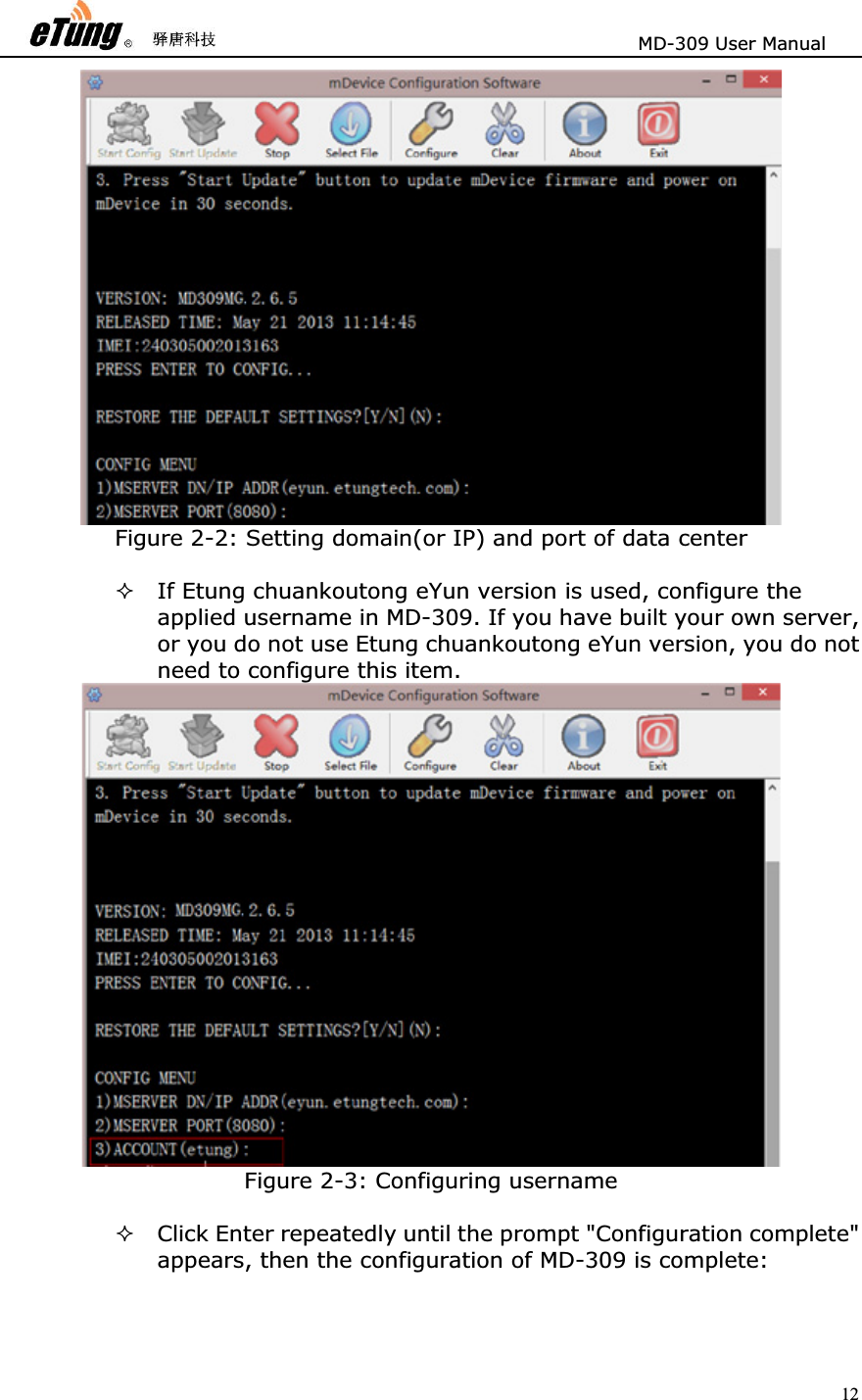
![MD-309 User Manual 1614) Connection mode[1:alwaysonline/2:wakeup online/3:onlineupon request] Configure connection mode. Alwaysonline means after power on itkeeps connected with data center,and auto connects afterdisconnection; Wakeup onlinemeans it does not connects afterpower on, and dials and connectwhen receiving wakeup SMS orwakeup call(wakeup phone numberand wakeup password need toconfigure), and after wakeup onlineif there is no data transfer incontinuous 5 minutes it willdisconnect; Online upon requestmeans it does not connects afterpower on, and when data need to besent from serial port it will betriggered to dial and connects datacenter, and after online uponrequest if there is no data transferin continuous 5 minutes it willdisconnect. Online upon requestincludes wakeup online functions,that is, when no data need to besent from serial port and it does not connect afterpower on, it can be triggered to dialand connect by wakeup SMS orwakeup call. 15) Ringing tone wakeup phonenumber () Configure ringing tone wakeupphone number when connectionmode is wakeup online. NULL or"ALL" means it does not checkcalling number, and there can bemultiple numbers separated by ",".](https://usermanual.wiki/Etung-Technology/MD-309/User-Guide-2689454-Page-16.png)
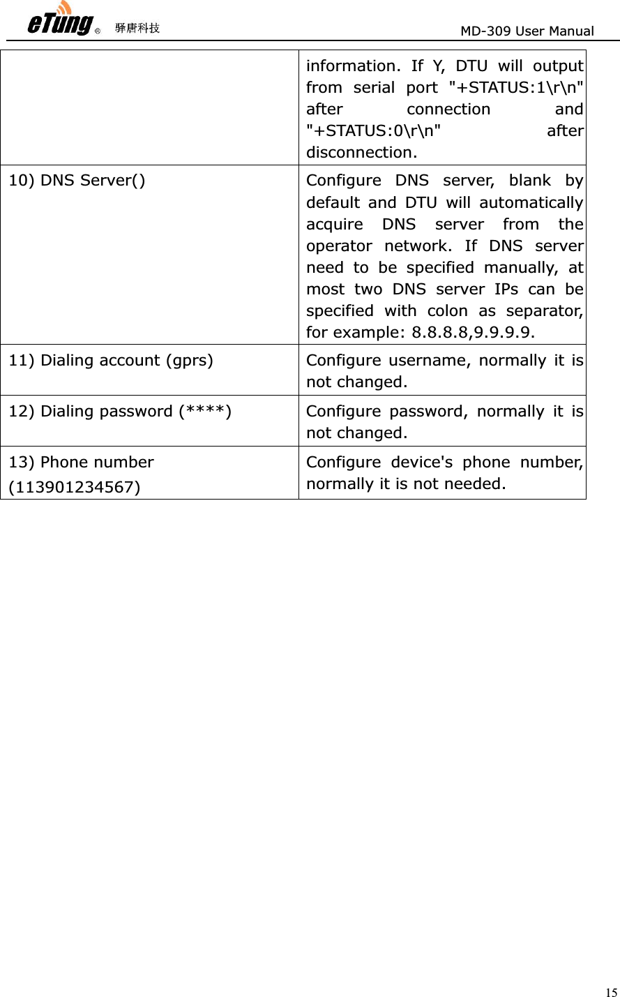
![MD-309 User Manual 1716) SMS wakeup password (1234) Configure password used for SMSwakeup when connection mode iswakeup online. If SMS wakeup isrequired, the SMS used to wakeupmust use this password. At thesame time, this password is also thepassword used to configure theSMS. 17) Heart-beat interval in seconds (60) Configure heart-beat interval inseconds. Heart-beat timeout is 3times of heart-beat interval. 18) Baud rate bps(9600) Configure baud rate on serial portwhen transferring data. 19) Data bits [5/6/7/8] (8) Configure data bits on serial portwhen transferring data. 20) Parity checking[N/E/O/M/S] (N) Configure parity checking bit onserial port when transferring data.N: No checking, E: Even checking,O: Odd checking, M: Mark checking,S: Space checking. 21) Stopping bit[1/1.5/2] (1) Configure stopping bit on serial portwhen transferring data 22) Flow control[N/H/S] (N) Configure flow control on serial portwhen transferring data. N: No flowcontrol, H: Hard flow control, S:Soft flow control. 23) Debugging mode[Y/N] (N) Configure whether DTU is running indebugging mode. It will outputdebugging information underdebugging mode, but DTU cannottransfer data in debugging mode. Check signal quality[Y/N] (N) Configure whether to check signalquality where DTU is located. It canonly work properly with good orbetter signal quality. Table 2-1: Details of configuration parameters](https://usermanual.wiki/Etung-Technology/MD-309/User-Guide-2689454-Page-17.png)