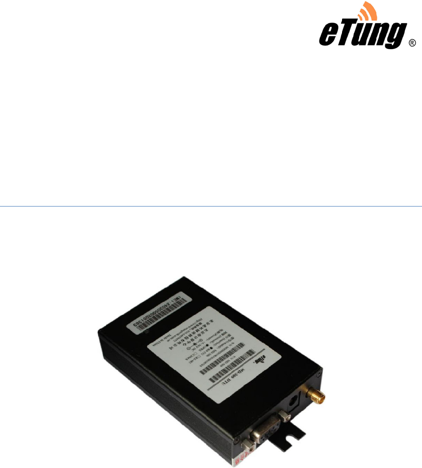
Etung Technology MD-309 Wireless Data Terminal User Manual MD 309
Etung Technology Co., Ltd Wireless Data Terminal MD 309
User Manual
MD-309 User Manual
Wireless Data Terminal
Etung Technology Co., Ltd
RM305 Geng Fang Plaza,jia 13 Huayuan Road Haidian Dist. Beijing,china
TEL:4008-909-611 FAX:010-64857815

MD-309 User Manual
2
Table of Contents
1. Product Introduction ....................................................................................................... 3
1.1 Brief Introduction ......................................................................................................... 3
1.2 Product Outlook............................................................................................................. 4
1.3 Standard Accessories.................................................................................................. 5
1.4 Working Mechanism .................................................................................................... 6
1.5 Specifications ................................................................................................................. 6
1.5.1 Technical Parameters...................................................................................... 6
1.5.2 Indicator Light Description............................................................................ 7
1.5.3 Serial Port Definition ....................................................................................... 8
1.6 Technical Advantages ................................................................................................. 8
1.7 Typical Usecases........................................................................................................... 9
2. Device Configurations................................................................................................... 10
2.1 Configurations.............................................................................................................. 10
2.1.1 Preparation........................................................................................................ 10
2.1.2 Configuring MD-309 ...................................................................................... 10
2.2 Configuration Parameters ....................................................................................... 13
2.3 Restore to Default ...................................................................................................... 18
2.4 Firmware Update ........................................................................................................ 18
Appendix : Switching RS-485 to RS-232 .............................................................................. 21

MD-309 User Manual
3
1. Product Introduction
This chapter mainly introduces the outlook, accessories, specifications and
mechanism of MD-309.
1. Brief Introduction
2. Product Outlook
3. Accessories
4. Dimension
5. Working Mechanism
6. Specifications
7. Technical Advantages
8. Typical Usecases
1.1 Brief Introduction
MD-309 is a GPRS DTU produced by Etung in 2010. It can greatly
reduce customer’s DTU procurement and integration cost, and has
industrial-grade stability and reliability as well. MD-309 has more
reasonable cost control, with lower price; it can be regarded by
customers as an easy-to-use and useful GPRS DTU product.
MD-309 can connect quickly with RTU, PLC, or IPC, and implement
remote and transparent data transfer. It can be used widely in various
industries related to “Internet of things”:
In electric power industry, MD-309 can be used in data transfer areas
such as reactive compensation, distribution monitoring, electric meter
reading and lamp monitoring;
In water application industry, MD-309 can play in wireless
communication areas such as water meter reading, water resource
remote monitoring, and water transportation network monitoring;
In environment protection area, MD-309 can fully deserve GPRS
soldier in pollution online monitoring system such as Continuous
Emission Monitoring System(CEMS), water quality monitoring system;
In device maintenance area, such as elevator monitoring and
air-conditioner monitoring, MD-309 can be embedded quickly into
customer’s appliance and implement GPRS wireless data transfer;
In heating industry, MD-309 can connect with MODBUS concentrator to
implement heating meter reading, implement remote data transfer for
household heating measurement; it can also connect with PLC or
collector to implement remote monitoring of heat exchange station.
MD-309 User Manual
4
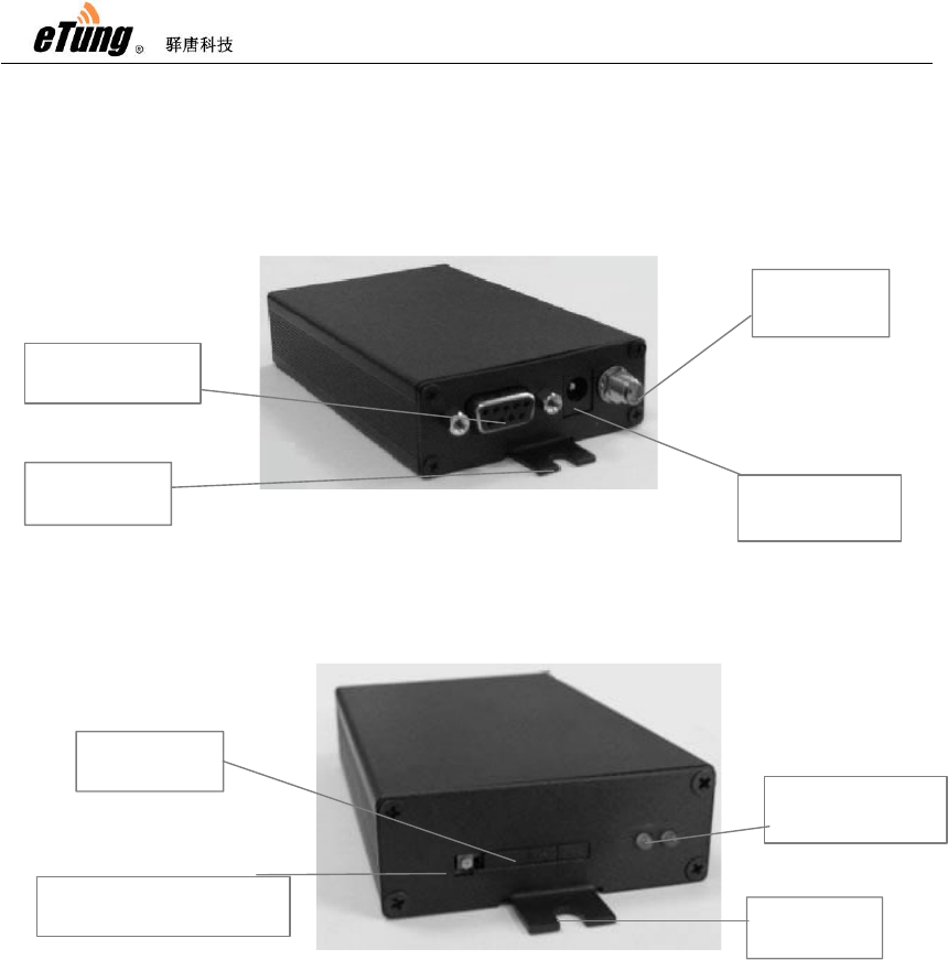
1.2 Product Outlook
Figure 1-1: MD-309 side view 1
Figure 1-2: MD-309 side view 2
ķSerial port
RS232/485
Ĺ
A
ntenna
pedestal
ĸDC power
interface
ľinstallation
handle
Ľindicator light
()green, red
ĻSIM card
holder
ļbutton used for ejecting
the sim card holder ľinstallation
handle

MD-309 User Manual
5
1.3 Standard Accessories
Figure 1-3: GSM sucking antenna
Figure 1-4: 9-pin and 9-hole direct serial line
Figure 1-5: Power supply
MD-309 User Manual
6
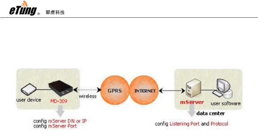
1.4 Working Mechanism
Figure 1-7: MD-309 working mechanism
After configuring IP address (or domain name) and port of the data
center in MD-309, it dials in GPRS wireless network to access the
internet; then it establishes connection to the preconfigured IP
address and port(i.e. mServer's listening port). On the other hand, the
user software system connects to the mServer via virtual serial port,
thus implements the wireless and bi-directional data communication
between user device and user software system.
1.5 Specifications
1.5.1 Technical Parameters
Basic Parameters
Power Supply: 12 V DC
Data interface: RS232/485/422/TTL
Network: GSM/GPRS
Frequency: 850/900/1800/1900MHz
Humidity: 95%@+40ºC
Dimensions: 103x64x24mm (excluding antenna and handle)
Communication
Adjustable baud rate on data interface
Support hard flow control on serial interface

MD-309 User Manual
7
Support standard TCP/IP protocol with both TCP and UDP
Support always online
Support SMS and ringing tone wakeup(wakeup online)
Stability
Host CPU: 32-bit ARM processor
Built-in soft/hard watch dog
Built-in TCP/IP protocol stack
Data Center
Support domain name
Compatible with various data center software
Configuration
Configurable via serial port
Configurable via hyper terminal with menus
1.5.2 Indicator Light Description
LED Indicator
Light
Color Status Description
Always light Connected to data center
Extinguished No connection to data center
Flash quickly Connecting to data center
Online Green
Flash slowly Dialing
Flash Transferring data/Standby Sending Red
Turn off No data transfer
Table 1-1 MD-309 indicator light description
MD-309 User Manual
8
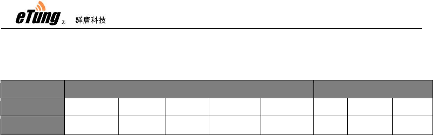
1.5.3 Serial Port Definition
Type RS-232 RS-485
Pin 2 3 5 7 8 2 3 5
Definition RXD(out) TXD(in) GND RTS(in) CTS(out) ABGND
Table 1-2: MD-309 serial port pin definition
1.6 Technical Advantages
Etung DTU products are advanced not only from hardware
industrialization, design rationality, software convenience, and
usage flexibility, but also from working stability. Its technical
advantages are easy to see:
Support sending SMS
Support GPRS and SMS as backup
Support modifying DTU configurations via SMS
Support modifying DTU configurations remotely at server side
Support querying SIM card number remotely, checking SIM
card balance and traffic within DTU
Support device remote re-boot
Support eYun platform, server building not needed and
plug-and-play
Support chuankoutong, virtual serial port programming not
needed
MD-309 User Manual
9
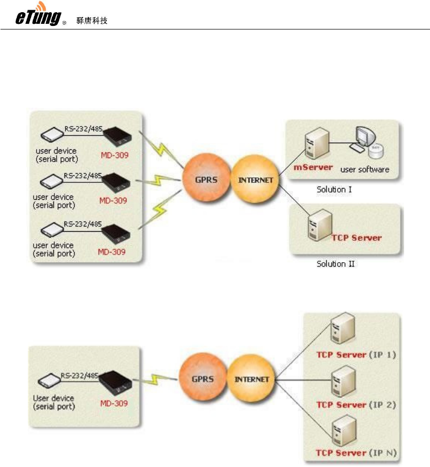
1.7 Typical Usecases
Figure 1-8: MD-309 multiple points to data center
Figure 1-9: MD-309 one point to multiple data centers

MD-309 User Manual
10
2. Device Configurations
This chapter introduces how to use MD-309 and related parameters.
1. Configurations
2. Parameters
3. Restore to default
4. Firmware Update
5. Remote Configurations
2.1 Configurations
2.1.1 Preparation
Serial line used to connect MD-309 with PC or user devices
GSM Antenna
Power Adapter
one SIM card, either from China Mobile or China Unicom, that
applies GPRS and can access internet directly via NET
2.1.2 Configuring MD-309
Connect MD-309 with PC using 9-pin 9-hole serial line (if MD-309
is with RS485 interface, we need an adapter from RS485 to
RS232, switch RS485 to RS232 and then connect with PC. For
details please see Appendix Switching RS-485 to RS-232)
Find and run MD-309 dedicated configuration executable
DTUcfg.exe either from the CD
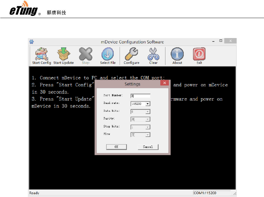
Click button "Settings" in the upper side of the user interface,
and in the popup dialog with title "Settings", select the serial port
that is used to configure MD-309, then click OK:
MD-309 User Manual
11
Figure 2-1: Setting serial port
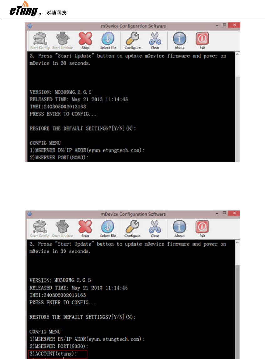
Click "Start configuration" based on the prompt, and power on
MD-309 quickly within 30 seconds; when the information about
MD-309 model appears, press Enter, then the first item of the
configuration menu appears: "1) Data center domain or IP ()",
then input domain of the data center: eyun.Etungtech.com (or
press Enter to use the default value in the bracket. The default
value is Etung server domain, please input your own domain or
IP address if you have built your own server).
Press Enter, then the second configuration item appears:
"Data center port (8080)", input mServer's listening port "8080"
(or press Enter directly to use the default value in the bracket.
This port is the public port of Etung server, input your own port if
you have built your own server or leased a dedicated port).
MD-309 User Manual
12
Figure 2-2: Setting domain(or IP) and port of data center
If Etung chuankoutong eYun version is used, configure the
applied username in MD-309. If you have built your own server,
or you do not use Etung chuankoutong eYun version, you do not
need to configure this item.
Figure 2-3: Configuring username
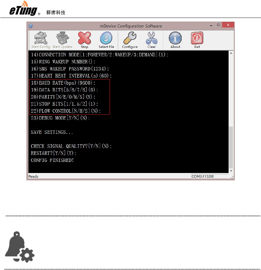
Click Enter repeatedly until the prompt "Configuration complete"
appears, then the configuration of MD-309 is complete:
MD-309 User Manual
13
Figure 2-4: Configuration complete
2.2 Configuration Parameters
Each configuration menu item of MD-309 includes the following
items (those with * are mandatory), details are in the following:
*Order number: includes digit and right bracket, for example
"10)"
*Name and unit: name of the configuration item (some items
have unit)
Optional values: the contents within "[]" are the values that are
allowed in this configuration item, multiple optional values are
separated with "/"
*Default value: i.e. the content within "()", If you press Enter to
skip this item configuration, the default value will be used.
Attention:
In reality, MD
-309 connects user devices via serial port,
so serial p ort attributes need to be configured in order to
match user device serial port.

MD-309 User Manual
14
For example:
15) digit bit [5/6/7/8] (8)
Order number Name and unit Optional values Default value
Below are the configuration items with MD-309 V2.8.5. Different
versions may have different configuration items.
Configuration Menu Item Description
RESTORE THE DEFAULT
SETTINGS?[Y/N](N)
Configure to restore to default or
not
1) MSERVER DN/ IP ADDR
(eyun.Etungtech.com)
Configure data center IP address or
domain
2) MSERVER PORT (8080) Configure data center port
3) ACCOUNT (Etung) Configure applied eYun username,
it is only required to configure if
chuankoutong eYun version is
used.
4) APN name () Configure wireless APN name,
normally it is not needed, and
default value is used, but users
with dedicated network adapter
need to configure this item.
5) Network
Protocol[UDP/TCP](TCP)
Configure data transport protocol,
either UDP or TCP.
6) Connect mServer[Y/N](Y) Configure whether to connect
mServer, Y by default to connect
mServer.
7) Self-define registration package
when no mServer connection ()
When the device does not connect
mServer, self-define registration
package.
8) Self-define heart-beat package
when no mServer connection ()
When the device does not connect
mServer, self-define heart-beat
package.
9) Serial port output connection
information[Y/N](N)
Configure whether to output
connection information from serial
port, N by default, i.e. do not output
MD-309 User Manual
15
information. If Y, DTU will output
from serial port "+STATUS:1\r\n"
after connection and
"+STATUS:0\r\n" after
disconnection.
10) DNS Server() Configure DNS server, blank by
default and DTU will automatically
acquire DNS server from the
operator network. If DNS server
need to be specified manually, at
most two DNS server IPs can be
specified with colon as separator,
for example: 8.8.8.8,9.9.9.9.
11) Dialing account (gprs) Configure username, normally it is
not changed.
12) Dialing password (****) Configure password, normally it is
not changed.
13) Phone number
(113901234567)
Configure device's phone number,
normally it is not needed.

MD-309 User Manual
16
14) Connection mode[1:always
online/2:wakeup online/3:online
upon request]
Configure connection mode. Always
online means after power on it
keeps connected with data center,
and auto connects after
disconnection; Wakeup online
means it does not connects after
power on, and dials and connect
when receiving wakeup SMS or
wakeup call(wakeup phone number
and wakeup password need to
configure), and after wakeup online
if there is no data transfer in
continuous 5 minutes it will
disconnect; Online upon request
means it does not connects after
power on, and when data need to be
sent from serial port it will be
triggered to dial and connects data
center, and after online upon
request if there is no data transfer
in continuous 5 minutes it will
disconnect. Online upon request
includes wakeup online functions,
that is, when no data need to be
sent from serial
port and it does not connect after
power on, it can be triggered to dial
and connect by wakeup SMS or
wakeup call.
15) Ringing tone wakeup phone
number ()
Configure ringing tone wakeup
phone number when connection
mode is wakeup online. NULL or
"ALL" means it does not check
calling number, and there can be
multiple numbers separated by
",".

MD-309 User Manual
17
16) SMS wakeup password (1234) Configure password used for SMS
wakeup when connection mode is
wakeup online. If SMS wakeup is
required, the SMS used to wakeup
must use this password. At the
same time, this password is also the
password used to configure the
SMS.
17) Heart-beat interval in seconds
(60)
Configure heart-beat interval in
seconds. Heart-beat timeout is 3
times of heart-beat interval.
18) Baud rate bps(9600) Configure baud rate on serial port
when transferring data.
19) Data bits [5/6/7/8] (8) Configure data bits on serial port
when transferring data.
20) Parity checking[N/E/O/M/S] (N) Configure parity checking bit on
serial port when transferring data.
N: No checking, E: Even checking,
O: Odd checking, M: Mark checking,
S: Space checking.
21) Stopping bit[1/1.5/2] (1) Configure stopping bit on serial port
when transferring data
22) Flow control[N/H/S] (N) Configure flow control on serial port
when transferring data. N: No flow
control, H: Hard flow control, S:
Soft flow control.
23) Debugging mode[Y/N] (N) Configure whether DTU is running in
debugging mode. It will output
debugging information under
debugging mode, but DTU cannot
transfer data in debugging mode.
Check signal quality[Y/N] (N) Configure whether to check signal
quality where DTU is located. It can
only work properly with good or
better signal quality.
Table 2-1: Details of configuration parameters
MD-309 User Manual
18
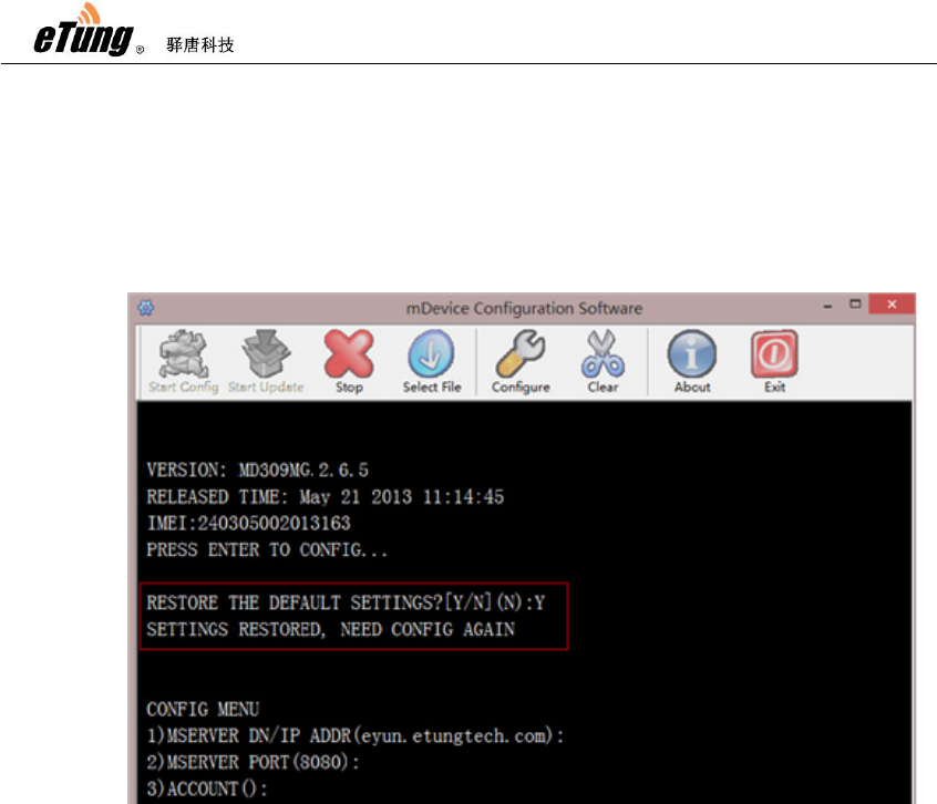
2.3 Restore to Default
According to the description of "Configuring MD-309", after
entering MD-309 configuration interface, the first item is "Restore
to default" option, input "Y" and press Enter, then the configuration
will be restored to default.
Figure 2-5: Restore to default
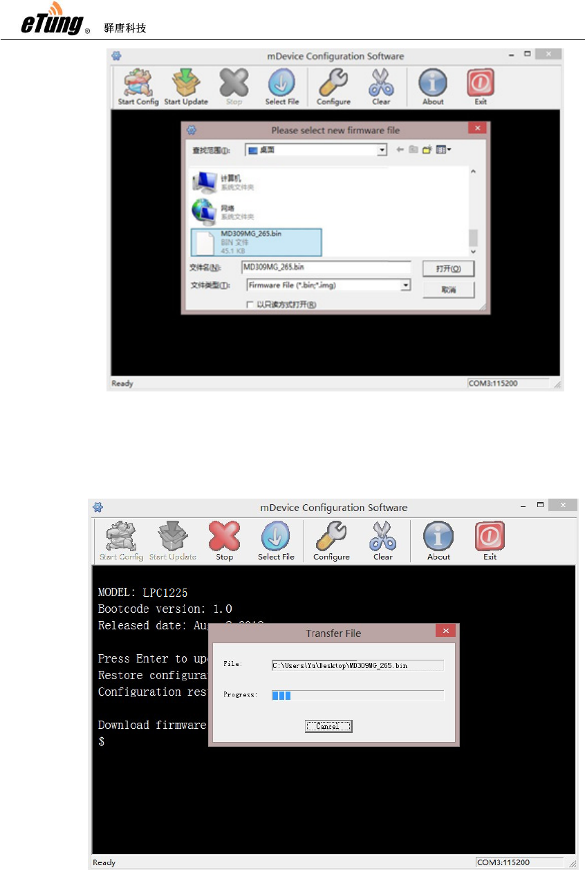
2.4 Firmware Update
Ask Etung for firmware software
According to the description of "Configuring MD-309", connect
MD-309 with PC via 9-pin 9-hole serial line, run MD-309
configuration executable, and set the serial port used to update
MD-309.
Click "Select file", then select the file (.bin) to update, and click
"Open".
MD-309 User Manual
19
Figure 2-6: Select file to update
Click "Start to update", then power on the device quickly within
30 seconds.
Figure 2-7: Firmware Update
MD-309 User Manual
20
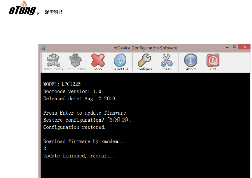
After update is complete the device will reboot automatically,
then in the user interface a prompt "Update finished" will appear.
Figure 2-8: Update complete

MD-309 User Manual
21
Appendix : Switching RS-485 to
RS-232
When configuring Etung device with RS-485 interface, in order to connect the
device to PC, it is required to switch RS-485 interface to RS-232 interface.
Etung provides two kinds of switching methods: via RS-485 to RS-232
convertor, and via 9-pin adapter serial line. Details are described below.
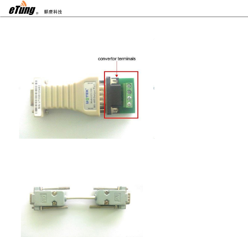
1) RS-485 to RS-232 Convertor
This method requires a RS-485 to RS-232 convertor (as shown in
Figure Appendix 3-1), as well as an adapter line from RS-485 to RS232 (as
shown in Figure Appendix 3-2), this line is delivered for free by Etung when
MD-309 User Manual
22
customer buys devices the first time.
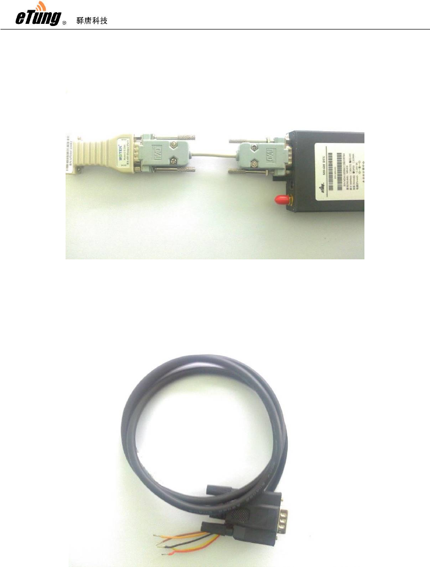
Connect the 9-pin end of the adapter line to the 9-hole serial port of the
device, connect the other end of the adapter line to the 9-pin end of the
convertor (not including convertor terminal) as shown in Figure Appendix
3-3, and then connect the 9-hole end of the convertor to PC.
Figure Appendix 3 -1:RS-485 to RS-232 Convertor
Figure Appendix 3 -2:Adapter line from RS -485 to RS
-232
MD-309 User Manual
23
Figure Appendix 3-3: connection diagram
2) 9-pin adapter serial line(RS-485 serial line)
This method requires RS-485 to RS-232 convertor, and 9-pin adapter serial
line (as shown in Figure Appendix 3-4).
Figure Appendix 3-4: 9-pin adapter serial line
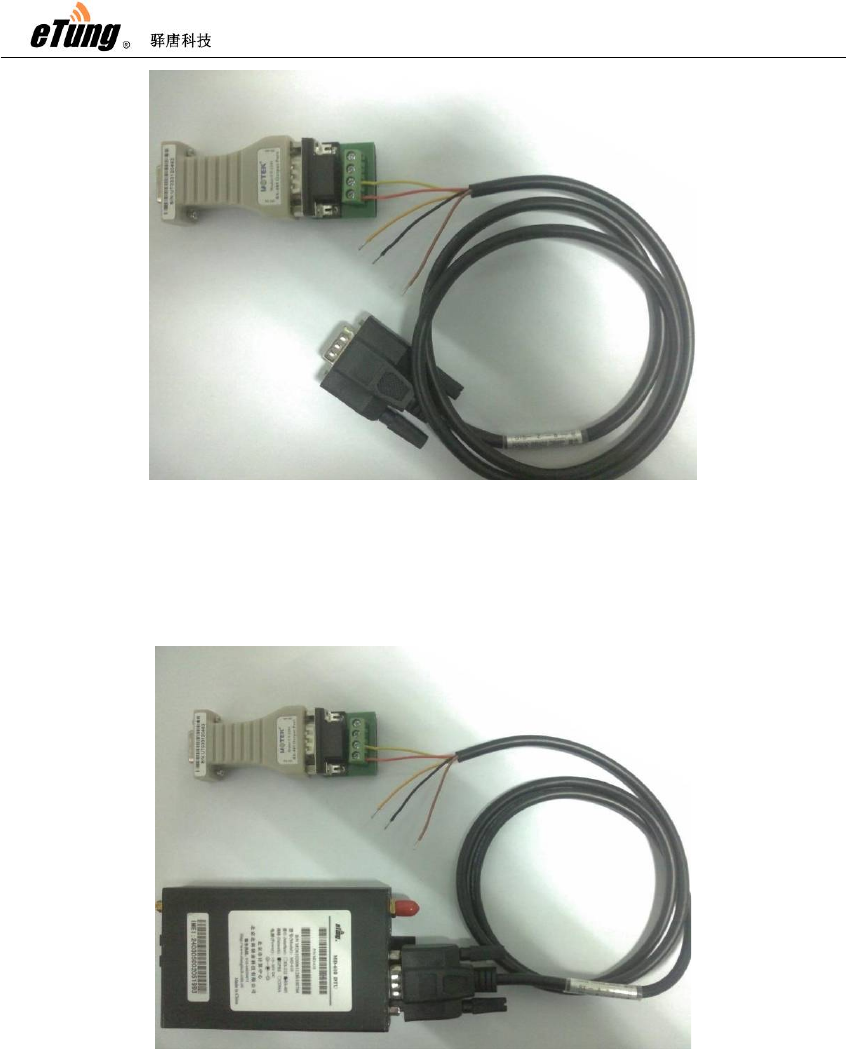
First, connect the red and yellow line of the line end on 9-pin adapter serial
line to the convertor terminal of the convertor, the order is: plug the red
line into T/R+ port of the terminal, and yellow line into T/R- port of the
terminal, and other lines are not required to connect, as shown in Figure
Appendix 3-5.
MD-309 User Manual
24
Figure Appendix 3-5: Line connection order
Then, connect the 9-pin end of the 9-pin adapter serial line to the interface
of RS-485 device, and connect 9-hole end of the RS-485 to RS-232
convertor to PC, as shown in Figure Appendix 3-6.
Figure Appendix 3-6: 9-pin adapter connection diagram
FCC Certification Requirements
Caution: Any changes or modifications in construction of this device which are not
expressly approved by the party responsible for compliance could void the user's authority
to operate the equipment.
This device complies with part 15 of the FCC Rules. Operation is subject to the following
two conditions: (1) This device may not cause harmful interference, and
(2) This device must accept any interference received, including interference that may
cause undesired operation.
The manufacturer is not responsible for any radio or TV interference caused by
unauthorized modifications to this equipment. Such modifications could void the user’s
authority to operate the equipment.
This equipment has been tested and found to comply with the limits for a Class B digital
device, pursuant to Part 15 of the FCC Rules. These limits are designed to provide
reasonable protection against harmful interference in a residential installation. This
equipment generates, uses and can radiate radio frequency energy and, if not installed
and used in accordance with the instructions, may cause harmful interference to radio
communications. However, there is no guarantee that interference will not occur in a
particular installation. If this equipment does cause harmful interference to radio or
television reception, which can be determined by turning the equipment off and on, the
user is encouraged to try to correct the interference by one or more of the following
measures:
-- Reorient or relocate the receiving antenna.
-- Increase the separation between the equipment and receiver.
-- Connect the equipment into an outlet on a circuit different from that to which the receiver
is connected.
Consult the dealer or an experienced radio/TV technician for help.
7KHDQWHQQDVXVHGIRUWKLVWUDQVPLWWHUPXVWEHLQVWDOOHGWRSURYLGHDVHSDUDWLRQGLVWDQFHRIDW
OHDVWFPIURPDOOSHUVRQV