Everspring Industry Co AN163 On/Off Plug with power meter User Manual
Everspring Industry Co Ltd On/Off Plug with power meter
UserManual.wiki
>
Everspring Industry Co
>
AN163 User Manual
User manual
Navigation menu
Upload a User Manual
Namespaces
Wiki Guide
HTML
PDF
Info
Views
User Manual
Discussion / Help
Navigation
![2 2. Within 1 second, press On/Off button again for 5 seconds until LED is off. 3. IDs are excluded. 2-second on, 2-second offAssociation 1. Have Z-Wave Controller entered association mode. Or Pressing On/Off button three times within 1.5 seconds will enter association mode Press On, for on Press Off, for off 2. There are two groupings - 1 and 2. Refer to Z-Wave’s Groups as described on page 3 & 4. Ensure that the unit is OFF before performing Inclusion/Exclusion/Reset.Failed or successful results in including/excluding the node ID can be viewed from the Z-Wave Controller. LED Indication To distinguish what mode the Module is in, view from the LED for identification. State Type LED Indication Normal Under normal operation, toggle On/Off button between On and Off. When pressing On, LED lights up, whereas Off, LED is off. No node ID Under normal operation, when the Module has not been allocated a node ID, the LED flashes on and off alternately at 2-second intervals. By pressing On/Off button, it will stop flashing temporarily. However, after unplugging and reconnecting the Module, the LED will flash on and off alternately at 2-second intervals. Overload When overload state occurs, the Module is disabled of which LED flashes on and off alternately for 30 seconds at 0.1 second intervals. Overload state can be cleared by unplugging and reconnecting the Module to the wall outlet. Choosing a Suitable Location 1. Do not locate the Module facing direct sunlight, humid or dusty place. 2. The suitable ambient temperature for the Module is 0°C~40°C. 3. Do not locate the Module where exists combustible substances or any source of heat, e.g. fires, radiators, boiler etc. 4. After putting it into use, the body of Module will become a little bit hot of which phenomenon is normal. Installation 1. Plug this On/Off Module into a wall outlet near the load to be controlled. 2. Plug the load into the Module. Make sure the load to be controlled does not exceed 1440 watts. 3. Press the button or switch on the load to the ON position. 4. To manually turn ON the Module, press and release the On/Off button. The LED will turn ON, and the load plugged into the Module will also turn ON. 5. To manually turn OFF the Module, simply press and release the On/Off button. The LED will turn OFF and the load plugged into the Module will also turn OFF. Programming 1. Basic Command Class / Binary Switch Command Class The Module will respond to BASIC and BINARY commands that are part of the Z-Wave system. 1-1 BASIC_GET / BINARY_SWITCH_GET Upon receipt of the following commands from a Z-Wave Controller, the Module will report its On/Off state to the Controller. Basic Get Command: [Command Class Basic, Basic Get] Basic Report Command: Report OFF: [Command Class Basic, Basic Report, Value = 0(0x00)] Report ON:[Command Class Basic, Basic Report, Value = (255)0xFF] Binary Switch Get Command:[Command Class Switch Binary, Switch Binary Get] Binary Switch Report Command: Report OFF:[Command Class Switch Binary, Switch Binary Report, Value =0(0x00)] Report ON:[Command Class Switch Binary, Switch Binary Report, Value = (255)0xFF]](https://usermanual.wiki/Everspring-Industry-Co/AN163/User-Guide-2248775-Page-2.png)
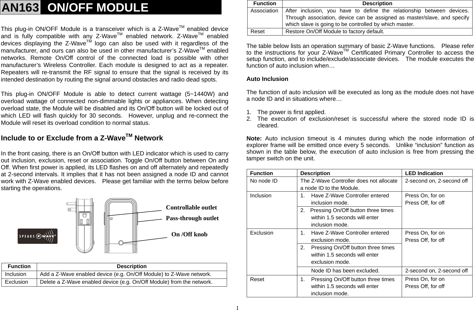
![3 1-2 BASIC_SET / SWITCH_BINARY_SET Upon receipt of the following commands from a Z-Wave Controller, the load attached to the Module will turn on or off. [Command Class Basic, Basic Set, Value = (255)0xFF]: the load attached to the Module turns on. [Command Class Basic, Basic Set, Value = 0(0x00)]: the load attached to the Module turns off. [Command Class Switch Binary, Switch Binary Set, Value = (255)0xFF]: the load attached to the Module turns on. [Command Class Switch Binary, Switch Binary Set, Value = 0(0x00)]: the load attached to the Module turns off. 2. Z-Wave’s Groups (Association Command Class Version 2) The Module can be set to send reports to or to control associated Z-Wave devices. It supports two association groups with one node support for Grouping 1 and four nodes support for Grouping 2. For grouping 1, the Module will report its latest status to Z-Wave Controller. There are two conditions of controlling the associated Z-Wave devices in grouping 2. In order to control associated Z-Wave devices, the prerequisite is to enable the BASIC_SET command. (see 2-2-1 for details) Condition 1: Upon receipt of the commands from Z-Wave Controller, the Module will control all devices associated in grouping 2 for On or Off operation. Condition 2: Pressing On/Off button directly on the Module, all devices associated with the Module will be turned on or off simultaneously. Grouping 1 includes ALARM_REPORT, SWITCH_BINARY_REPORT, METER_REPORT_COMMAND Grouping 2 includes BASIC_SET 2-1 Grouping 1 (Maximum Node 1) 2-1-1 POWER_APPLIED command The Module will send ALARM_REPORT command to the nodes of Grouping 1 to inform the Z-Wave Controller that the Module is connected to a wall outlet properly. ALARM_REPORT Command: [Command Class Alarm, Alarm Type = 0x02, Alarm Level = 0x01] 2-1-2 On/Off Event Report (TRUE STATE) When toggling between “on” and “off ” button, it will send Switch Binary Report to the nodes of Grouping 1. However by setting a specified period of time (referred to as the “true period”) as indicated below in item 3 -- Z-Wave’s configuration parameter 1, toggle On/Off button between “on” and “off” will not send Switch Binary Report instantly. As a result, when pressing “on” or “off” button for the first time, the Module will be locked out for the preset true period during which shifting between “on” and “off” button will not send Switch Binary Report. It will be unlocked until the preset true period is expired. As soon as the Module is unlocked, it will check if the current state is different from the initial state. If it is different, the Module will send Switch Binary Report to the nodes of Grouping 1 immediately; whereas if it is the same, the Module will not send report to the nodes of Grouping 1. The true period can be set through configuration command class. Refer to the true period of configuration. 2-1-3 Binary Switch Report Command ON:[Command Class Switch Binary, Switch Binary Report, Value =(255)0xFF] OFF:[Command Class Switch Binary, Switch Binary Report, Value =0(0x00)] 2-1-4 Meter Report Command The Module will report its instant power consumption to the node of Grouping 1. For detailed description of meter report command, refer to page 4. 2-2 Grouping 2 (Max. Nodes 4) 2-2-1 Control Other Z-Wave Devices (Basic Set) Enable or disable BASIC_SET command. Refer to the table below describing “send basic command to grouping 2”. Note: AN163 can associate up to 4 pc of AN163, acting as an active and passive device respectively. The active one cannot be set and controlled by the passive device.](https://usermanual.wiki/Everspring-Industry-Co/AN163/User-Guide-2248775-Page-3.png)
![4 3. Z-Wave’s Configuration Configuration Parameter Function Size (Byte) Value Unit Default Description 1 True Period 1 0-120 100ms 10 10*100ms=1second 0: Disable 2 Send Basic Command toGroup 2 1 0,1 0 0:Disable 1:Enable 3 Meter ReportPeriod (W) 2 0-3240 (9Hr) 10s 3 3*10=30seconds 0:Disable 4 Meter ReportPeriod (kWh)2 0-10080 (1 week) 1min 1440 1*1440=1440min 0:Disable 3-1 The true period: If the setting is configured for 1 second, pressing On or Off button alternately within 1 second will not send out RF command. After 1 second has elapsed, it will examine if current On/Off state is the same as the initial 1 second. If the same, no RF command will be sent, whereas if it is different, RF command will be sent to update the status. The maximum interval is 12 second (100ms*120=12000ms). 3-2 Send basic command to grouping 2: If the setting is configured for 0, whenever pressing On/Off button manually on the Module or receiving basic_set command from the Z-Wave Controller, the Module will not send command to other devices of Grouping 2 for On or Off operation; whereas if the setting is configured for 1, the Module will send command to other devices of Grouping 2 for On or Off operation. 3-3 Meter Report Period (W): If the setting is configured for 30 seconds, the Module will report its instant power load (W) every 30 seconds to Z-Wave Controller. The maximum interval to report its instant power consumption is 9 hours (10s*3240/3600=9hr). 3-4 Meter Report Period (kWh): If the setting is configured for 1440 minutes (24Hr), the Module will report its instant power load (kWh) every 24 hours to Z-Wave Controller. The maximum interval to report its instant power consumption is 1 week (1min*10080/60=168hr =1 week). 4. Meter Command Class The Module will report its instant or accumulated power consumption to Z-Wave Controller. If the calculation of accumulated power consumption is needed, the Z-Wave Controller needs to be sent Meter Reset Command to the Module, enabling to reset to zero. 4-1 Instant Power Consumption of Module When receiving Meter Get Command, it will report Meter Report Command to the node of Grouping 1. Meter Get Command: [Command Class Meter, Meter Get, Scale =0x02(W)] Meter Report Command: [Command Class Meter,Meter Report,Rate Type+Meter Type,Precision+Scale+ Size,Meter Value 1,Meter Value 2] Rate Type = 0x01 Meter Type = 0x01 Precision = 0 Scale = 0x02(W) Size = 2 Bytes (Meter Value) Meter Value 1 = High Byte (W) Meter Value 2 = Low Byte (W) Example: Meter Value 1 = 0x01(W) Meter Value 2 = 0xF4(W) Meter (W) = Meter Value 1*256 + Meter Value 2 = (1x1)x256 + [(15x16)+(4x1)] = 500(W) 4-2 Accumulated Power Consumption (KW/h) When receiving Meter Get Command, it will report Meter Report Command to the node of grouping 1. Meter Get Command: [Command Class Meter, Meter Get, Scale = 0x00 KW/h)] Meter Report Command: [Command Class Meter,Meter Report,Rate Type + Meter Type, Precision+ Scale + Size,Meter Value 1,Meter Value 2,Meter Value 3, Meter Value 4]](https://usermanual.wiki/Everspring-Industry-Co/AN163/User-Guide-2248775-Page-4.png)
![5 Rate Type = 0x01 Meter Type = 0x01 Precision = 2 Scale = 0x00 (KWh) Size = 4 (4 bytes Meter Value) Meter Value 1 = (W) MSB Meter Value 2 = (W) Meter Value 3 = (W) Meter Value 4 = (W) LSB Example: Scale = 0x00 (KWh) Precision = 2 Size = 4 (4 Bytes KW/h) Meter Value 1 = 0x00 Meter Value 2 = 0xB8 Meter Value 3 = 0x1A Meter Value 4 = 0x12 Accumulated power consumption (KW/h) = (Meter Value 2*65536) + (Meter Value 3*256) + (Meter Value 4) = 120652.98 (KW/h) Note: When connecting to smaller loading, the module needs longer period of time to accumulate the value of power consumption. It is highly recommended that you expand its loading and prolong measuring period. For instance, when connecting to 100 wattage for one hour, the value of power consumption will be added as about 0.1, whereas for 1000 wattage, it will be added as about 1.0. 4-3 Clearing accumulated power consumption (KW/h) Meter Reset Command: [Command Class Meter, Meter Reset] 5. Command Classes The Module supports Command Classes including… * COMMAND_CLASS_SWITCH_BINARY * COMMAND_CLASS_BASIC * COMMAND_CLASS_MANUFACTURER_SPECIFIC * COMMAND_CLASS_VERSION * COMMAND_CLASS_SWITCH_ALL * COMMAND_CLASS_ASSOCIATION_V2 * COMMAND_CLASS_METER_V2 * COMMAND_CLASS_ALARM * COMMAND_CLASS_CONFIGURATION Troubleshooting Symptom Cause of Failure Recommendation The Module not working and LED off 1. The Module is not plugged into the electrical outlet properly 2. The Module break down 1. Check power connections 2. Don’t open up the Module and send it for repair. The Module LED illuminating, but cannot control the ON/OFF Switch of the load attachedCheck if the load plugged into the Module has its own ON/OFF switch Set the ON/OFF switch of the load attached to ON The Module LED illuminating, but the Detector cannot control the Module 1. Not carry out association 2. Same frequency interference 1. Carry out association 2. Wait for a while to re-try LED keep flashing 30 seconds, but cannot control Overload occurs Remove the load attached. Ensure the max. load does not exceed 1440W. Press the knob several times rapidly and seems not function correctly The On/Off knob is also the learn button; could be judged for learning ID For turning on/off, the interval between each press should be at least 2 seconds Specification Frequency Range 908.42 MHzOperating Voltage 120V/60HzMaximum Load 1440W ResistiveEffective Range 30 Meters Indoor (Open Space)Operating Temperature 0°C - 40°COperating Humidity 85%RHProtection Degree Indoor useFCC ID FU5AN163* Specifications are subject to change without notice A501112126R 2013/12](https://usermanual.wiki/Everspring-Industry-Co/AN163/User-Guide-2248775-Page-5.png)