Everspring Industry Co CC128 SOLAR Camera User Manual CC128
Everspring Industry Co Ltd SOLAR Camera CC128
Users Manual
1
Figure 2
Figure 1
C128U SOLAR CAMERA KIT
Installation and Operating Manual
Introduction
The Solar Camera is designed to economically provide safety,
security, convenience to your home and business. Its solar
panel collects daylight and maintains a charge to the battery of
the camera during daylight hours. A negligible amount of energy
is released by the rechargeable battery to operate the camera
during nighttime.
The components included in the C128U Solar Camera Kit:
¡´ 1 x Solar Camera with PIR and Solar Panel(Transmitter)
¡´ 1 x Audio & Video Receiver
¡´ 1 x Power Adapter for Receiver
¡´ 1 x 3 Feet RCA/SCRT Cable
¡´ 1 x 6V 1.2A Rechargeable Battery
¡´ 1 x 9V Alkaline Battery
¡´ 1 x Waterproof Rubber Plug
Caution
Pay attention to the following before you install:
1. Sufficient daylight: Solar panel
requires constant charge during
daylight hours. Please mount the
camera at the location that can
receive sufficient daylight exposure.
2. Detecting sensitivity: A passive
infrared sensor
operates by detecting
the objective
movement and heat.
When the temperature
of the moving object
and its surrounding
area are close in value, it may reduce
PIR’s sensitivity. The motion detector’s
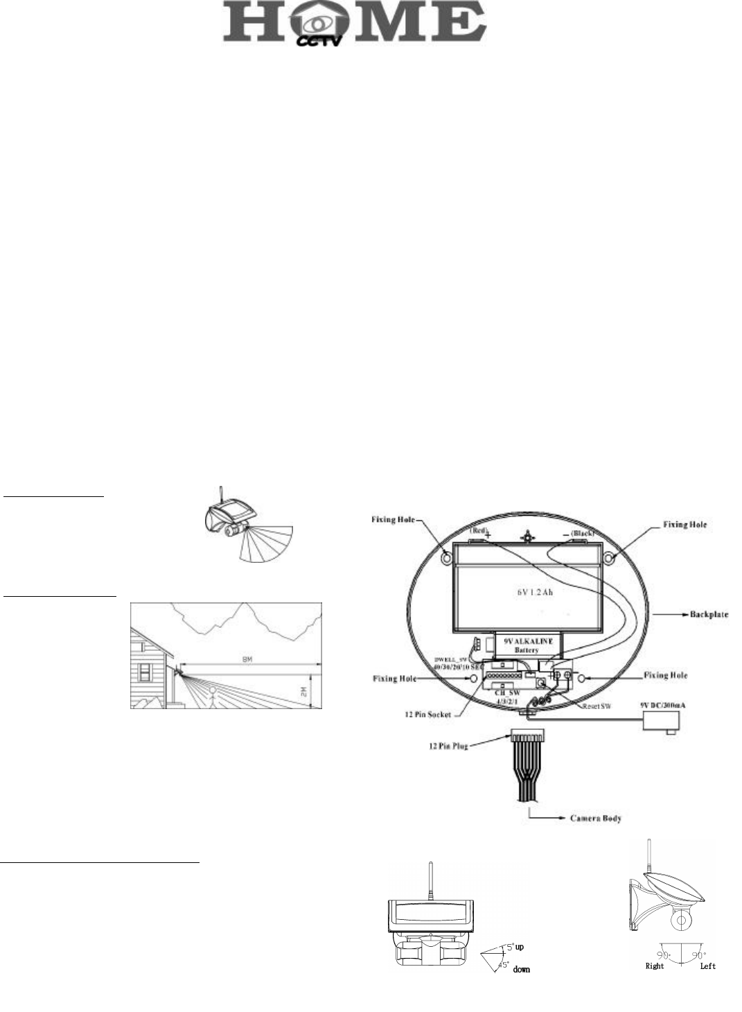
infrared beams radiate outward like the slat of a wooden fence.
Prior to mounting, keep in mind that the motion sensor is more
sensitive to the motion that crosses these “slats”, and less
sensitive to the motion that moves directly towards the sensor
(see Figure 1 and 2.)
3.Keep a light source during nighttime: The camera cannot work
in total darkness. Please bear in mind the camera's viewing
area must be illuminated with a suitable light source during
nighttime.
Installation
Step 1: Install the camera (refer to Figure 3):
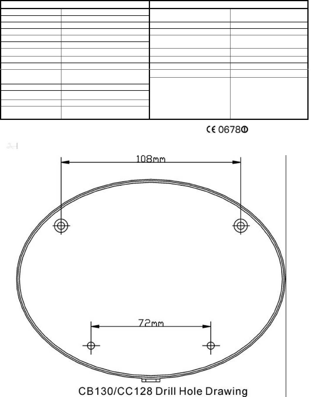
a. Use the fixing template provided to mark the position of the
four fixing holes. Drill four 5mm-diameter holes.
b. Mount backplate by inserting two screws into fixing holes on
the top edge of backplate. (All electronic components are
housed within the backplate.)
c. Adjust the “DWELL_SW(SW3)” knob on backplate to set up
transmission time (lock time) of images and voices. It can be
set as 10,20,30 or 40 seconds.
d. Adjust the “CH_SW” knob on backplate to set up a channel.
And remember which channel you selected.
e. Plug the camera’s 12 Pin plug (Cable) into socket on the
backplate, then secure the camera set (front cover) to the
backplate by inserting screws into two fixing holes on the
button edge of front cover and backplate. And then insert the
waterproof rubber plug into the hole at the bottom of front
cover.
f. The camera and PIR which under the main solar panel
cabinet can be swiveled upward to 5°, downward to 45°(refer
to Figure 4) and 90° horizontally (refer to Figure 5)
g. Adjust the camera and PIR angle according to your need.
Figure 3
Figure 5
Figure 4
2
Figure 6 European Version
Figure 7 American Version
Figure 7 American Version
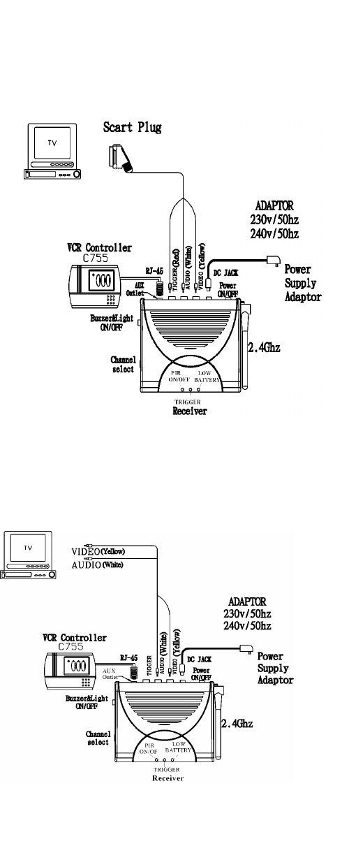
Step 2: Install Receiver Unit
(Two visions available: European and American)
European Version (refer to Figure 6):
To connect receiver to your TV:
1. Plug the 1M Scart connector cable that package
included into your TV.
2. Plug the other end, yellow (video), white (audio) and red
(trigger) RCA connectors into the corresponding RCA
connectors on the receiver.
American Version (refer to Figure 7):
To connect receiver to your TV:
1. Plug the yellow (video) and white (audio) RCA connectors
into TV socket.
2. Plug the yellow (video) and white (audio) RCA connectors
into the corresponding RCA connectors on the receiver.
Step 3: Install option accessory VCR Controller (refer to
Figure 6 or Figure 7)
By adding the optional VCR Controller (C755) will enable the
system to automatically record anyone who approaches your
premises. The VCR Controller will automatically switch your
VCR on to Record and Off once the person has left.
Plug RJ45 connector of VCR Controller (C755) in AUX outlet of
the receiver, and VCR will record the images and voices when
Camera detects movement. (Please refer to C755 manual for
installation and operation).
Operating Instruction:
(1) Buzzer/Light ON/OFF SW: Select “Buzzer/Light SW” at
"ON". When PIR camera is triggered, image and voices will
be transmitted. Upon receiving the signals, the receiver
sounds “Beep” twice in response and the LED will flash for
1 minute.
(2) Transmission time (lock time) of image and voices can be
set as 10, 20, 30, or 40 seconds by carefully adjusting the
“DWELL_SW (SW3)” knob of Camera.
(3) When lock time of trigger is over, the camera will continue
transferring image and voices if PIR sensor is still under
triggered condition. Otherwise, the camera will send an
“OFF” signal to the receiver and shut down images and
voices.
(4) When PIR of the camea is triggered, the camera will send
2.4GHz RF signal to the receiver. Thus, images and voices
will be displayed on TV or monitors through the receiver.
(5) When battery is low:
a. In the condition of camera on, Camera sends a signal to the
receiver to lighten the “Battery” LED and sound two “beeps”
for alert.
b. If battery is low during image transmitting, the image will
stay on for 5 seconds only. Then there will be two beeps
and the “Battery” LED will be on.
(6) If the camera battery is recharged to normal level, the low
Battery LED will be turned off when the camera is triggered
again.
You can also additionally have a 9V DC 300mA regulator power
AC adapter and wire it on S3 (refer to Figure 3) of backplate to
recharge and to transmit images and voices continuously.
Note:
(1) What you should do when the camera does not work properly:
a. Unscrew the camera (two screws on the edge of front cover)
b. Press “SW1” on Wall Mount to restore the system
c. Turn off the receiver, then turn it on.
d. Hang the camera on Wall Mount, and tighten 2 screws on
the bottom of the camera.
(2) When battery is low, video automatically reduces to 5
seconds to save battery.
(3) Position the receiver and set up channel first while installing,
then position the camera and set receiver in the same
channel with the camera.
(4)When the image on TV is not clear, it means that somebody
may use the same channel as yours in your neighborhood.
You can change both channels on the backplate of camera
and the receiver. Remember to set the camera in the same
channel as that of the receiver.
3
SPECIFICATIONS
CC128 CA117
Camera Type CC128
Picture Type Color CMOS Operating Frequency 2400-2483MHz (for 4 channels)
TV System PAL/NTSC Transmission Range 75m in open space
Sensitivity 3Lux@F1.2 Channel Selection Switch 4 positions for 1~4 selection
Lens Angle 78° Diagonal
Lens 4.3mm F2.0 Buzzer & Light Switch 3 positions for buzzer & light on /
buzzer off/off
Camera Angle Left & Right 90°¡Ó 5°, Down 45°Power Switch 2 positions for power on/ off
Microphone Build in Triggered Buzzer & Light function Build in
Transmitting Frequency 2400~2483MHz (for 4 channels) Antenna Type Rod
AC Adapter 12VDC, 500mA AC adapter
Battery 1 x 9V back up battery, 1x 6V
rechargeable solar battery
Dwell Time Switch 4 positions for 10s/20s/30s/40s
Power Supply Source Solar Panel (110*160mm)
Channel Switch 4 positions for 1~4 selection
PIR Detect ion
Distance/Angle 8M/90° (under 28°C)
Connector 1 x RJ-45 for VCR Controller
1 x DC Jack for Power
3 x RCA Jack for triggered(red),
audio(white), video(yellow)
© 2002 Everspring Industry Co., All Rights Reserved
… ………………………………………………………………………………………………………………………………………..……
D/NL/F/E/B/S/CH