Everspring Industry Co CM422 Baby Monitor User Manual
Everspring Industry Co Ltd Baby Monitor
UserManual.wiki
>
Everspring Industry Co
>
CM422 User Manual
User manual
Navigation menu
Upload a User Manual
Namespaces
Wiki Guide
HTML
PDF
Info
Views
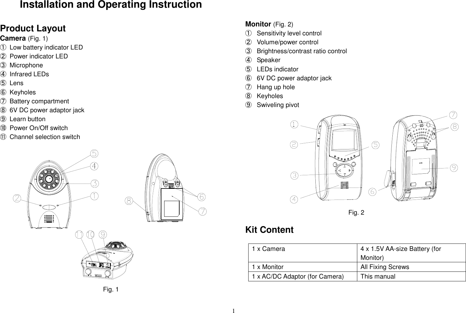
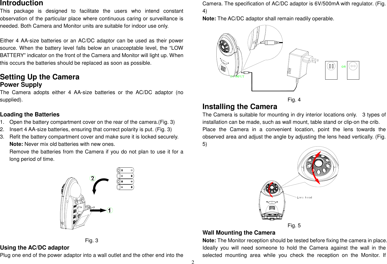
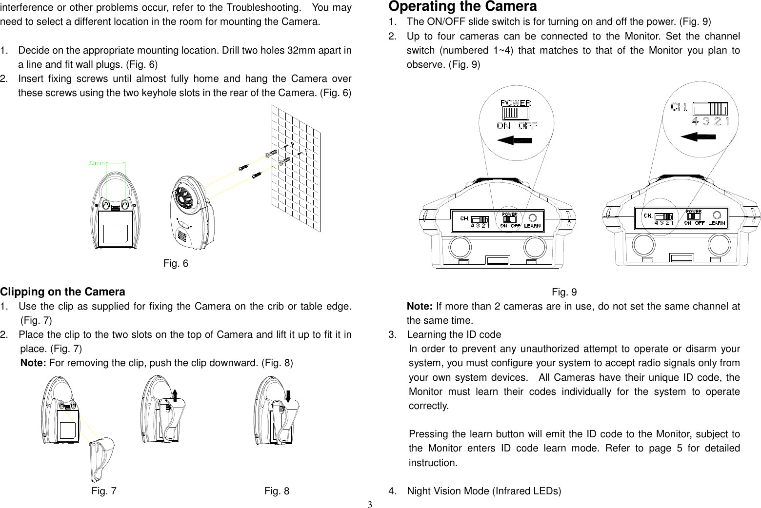
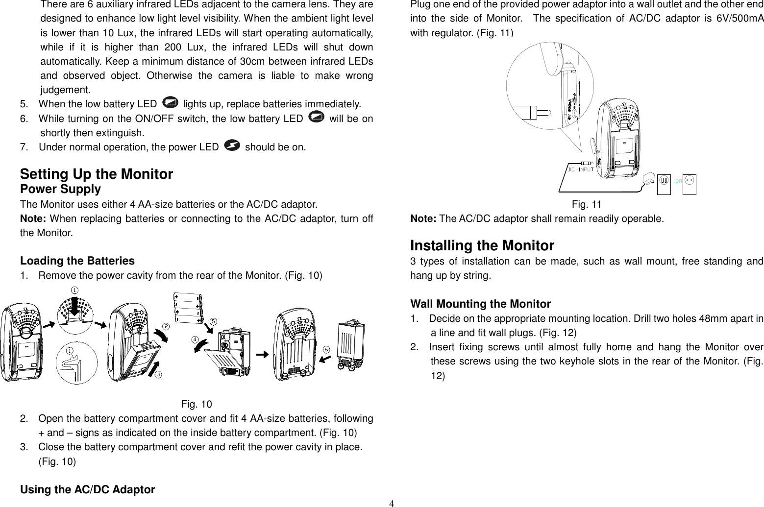
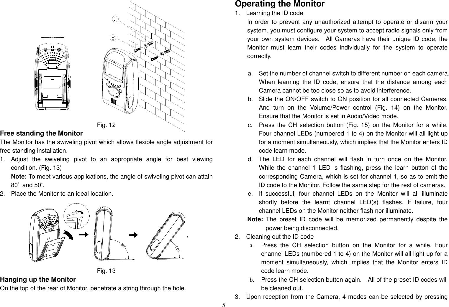
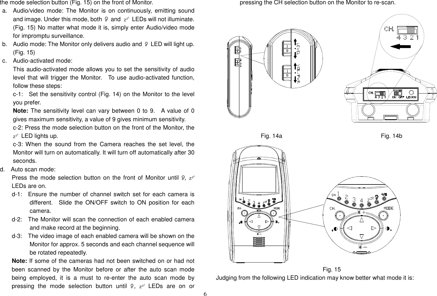
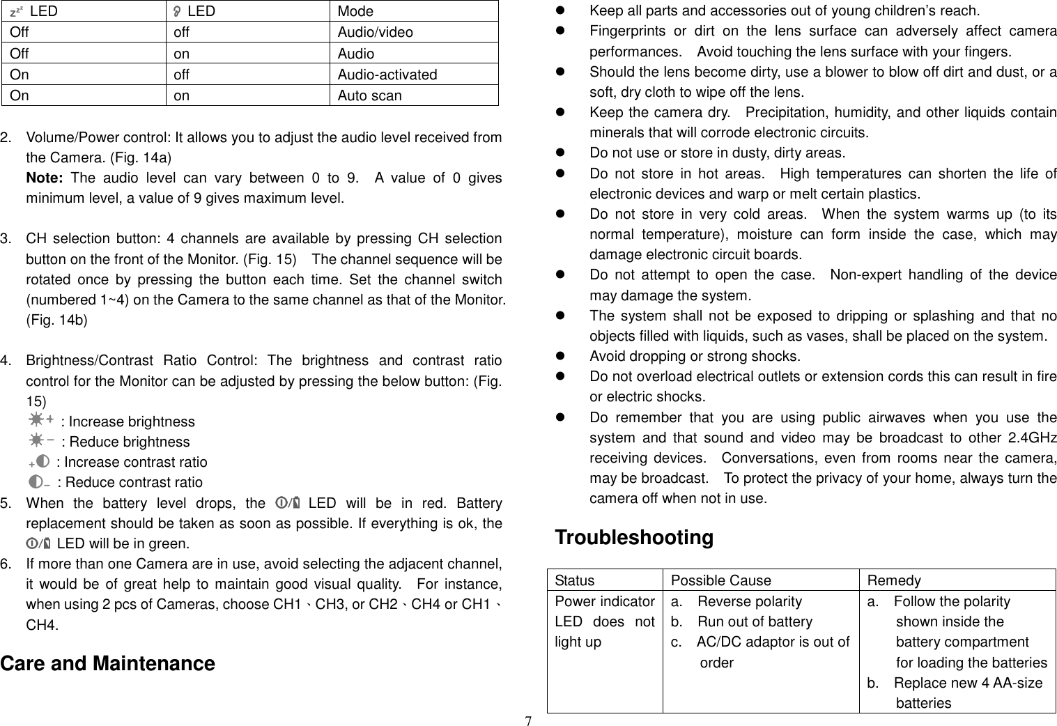
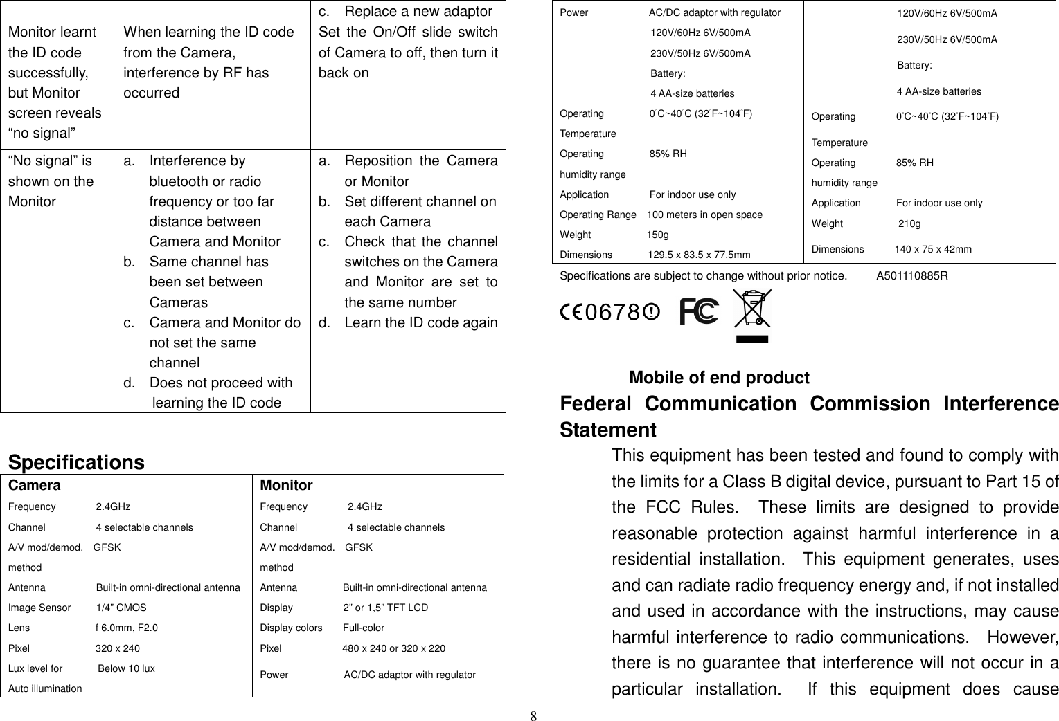
User Manual
Discussion / Help
Navigation