Everspring Industry Co HSP01 PIR Motion Detector User Manual HSP01 0 E868 PIR Homesys
Everspring Industry Co Ltd PIR Motion Detector HSP01 0 E868 PIR Homesys
UserManual.wiki
>
Everspring Industry Co
>
HSP01 User Manual
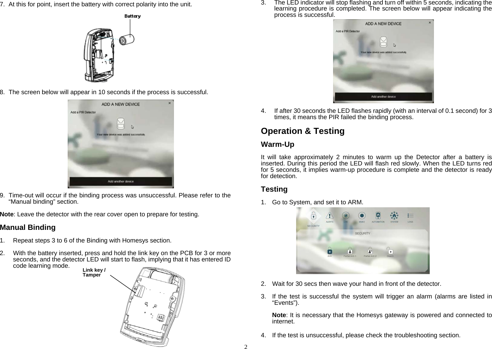
User manual
Navigation menu
Upload a User Manual
Namespaces
Wiki Guide
HTML
PDF
Info
Views
User Manual
Discussion / Help
Navigation