Everspring Industry Co HSP02 MOTION DETECTOR User Manual UserMan
Everspring Industry Co Ltd MOTION DETECTOR UserMan
UserMan
1
HSP02 MOTION DETECTOR
The Motion Detector is a Z-WaveTM enabled device which is fully compatible with
any Z-WaveTM enabled network. Z -WaveTM enabled devices displaying the
Z-WaveTM logo can also be used with the unit regardless of brand. Inclusion of this
Motion Detector in a Wireless Controller system allows remote control of connected
modules when the detector is triggered.
The Motion Detector is designed with two sensors - Passive Infra-Red (PIR) sensor
and light sensor - in order to fulfill the purpose of security and home automation.
When the detector is working with se curity appliances, it is acting as a security
device by detecting changes in infra-red radiation levels. If a person moves within
or across the detection field, a trigger radi o signal will be transmit ted to cause full
alarm condition. Alternatively, when the detector is working with home automation
appliances, the detector can detect both changes in infra-red radiation levels and
percentage of lux levels. At night, when a person moves within or across the field
of detection, a trigger radio signal will be transmitted so as to turn on the connected
lightings for better illumination.
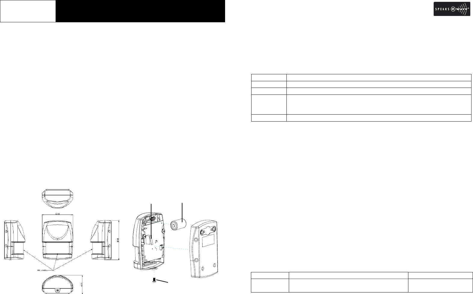
Overview and Battery Installation
The PIR Detector adopts a CR2 3.0V Lithium battery which under normal conditions
will have typical lifespan in excess of 1 year. To install the battery, simply undo the
fixing screw and rem ove the rear co ver, and then place the battery into the
compartment with polarity correctly fitted. Then refit and secure the rear cover.
Include to or Exclude from Z-WaveTM Network
In the rear casin g, there is a link key (t amper switch) which is used to carry out
inclusion, exclusion, association or reset. When the detector is first powered up,
the LED fla shes on and off alternately and repeatedly at 2-seco nd intervals. It
implies that i t has not been assigned a node ID and cannot work with Z-Wave
enabled devices. The detector will stay “awake” for 10 minutes when power is
first applied to allow time for configuration. Please get familiar with the term s
below before starting the operations.
Function Description
Inclusion Add a Z-Wave enabled device (e.g. Motion Detector) to Z-Wave network.
Exclusion Delete a Z-Wave enabled device (e.g. Motion Detector) from the network.
Association After inclusion, you have to define the re lationship between devices.
Trough association, device can be assi gned as master/slave, and spec ify
which slave is going to be controlled by which master.
Reset Restore Detector to factory default.
The table below lists an operation summary of b asic Z-Wave functions. Please
refer to the instructions for your Z-WaveTM Certificated Primary Controller to access
the setup function, and to include/exclude/associate devices. The detect or
executes the function of auto inclusion when…
Auto Inclusion
The function of auto inclu sion will b e executed as long as the detector does not
have node ID and in situations where…
1. The power is first applied.
2. The execution of exclusio n/reset is successful where the stored node ID is
cleared.
Note: Auto inclu sion timeout is 4 minute durin g which the nod e information of
explorer frame will be emit ted once every 5 seconds. Unlike “inclusion” function
as shown in the table below, the execution of auto inclusion is free from pressing
the link key on the detector.
Function Description Indication
No node ID The Z-Wave Controller does not allocate a
node ID to the unit.
2-second on, 2-second
off
Tamper Switch
/
Link Ke
y
Battery
Fixing Screw
2
Inclusion 1. Have Z-Wave Controller entered inclusion
mode.
2. Pressing link key 3 times within 1.5
seconds will enter inclusion mode.
3. The unit will stay “awake” for 10 minutes.
Exclusion 1. Have Z-Wave Controller entered exclusion
mode.
2. Pressing link key 3 times within 1.5
seconds will enter exclusion mode.
3. The unit will stay “awake” for 10 minutes. 2-second on, 2-second
off (for 2 minutes)
Reset 1. Press link key 3 times within 1.5 seconds.
2. Within 1 second, press and hold link key
for 5 seconds until LED is OFF.
3. IDs are cleared and all settings will be
reset to factory default.
2-second on, 2-second
off (for 2 minutes)
Association 1. Have Z-Wave Controller entered
association mode.
2. Pressing link key 3 times within 1.5
seconds will enter association operation.
The unit will stay “awake” for 10 minutes.
3. There are two groupings – 1 and 2. Refer
to Z-Wave’s Grouping as described on
page 4.
ÚIncluding a node ID allocated by Z-Wave Controller means inclusion. Excluding a node
ID allocated by Z-Wave Controller means exclusion.
ÚFailed or successful results in including/excluding the node ID can be viewed from the
Z-Wave Controller.
ÚWhen “Exclusion” is compl eted, the p arameter 1 of configur ation will be restored t o
default value, while other parameters will retain their settings before exclusion. Press
the tamper switch (link key) once and the green LED will flash for about 25 seconds.
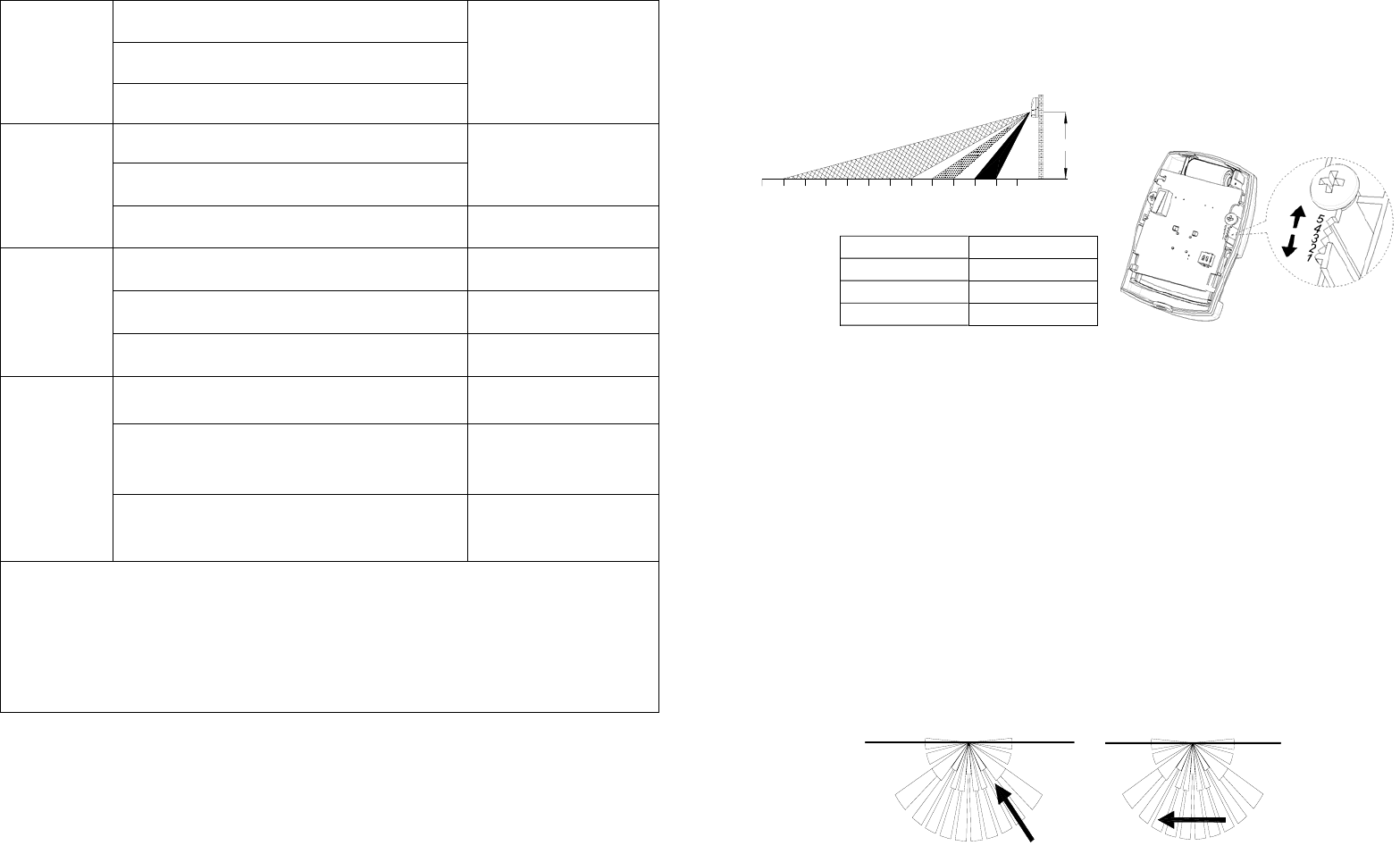
Choosing a Mounting Location
The PIR Detector is suitable for mounting in dry interior locations only.
The recommended position for a PIR Detector is in the corner of a room mounted at
a height between 1.8 and 2m. At this height, the detecto r will have a maximum
range of up to 9m with a field of view o f 110°, subject to the position for the P CB
being set in 5. (FIGURE 1& 2) The position of the PCB inside the PIR can be set to
5 different positions to adjust the range of the detector. Setting the PCB in position 3
will reduce the range to 6m approximately, with position 1 providing a range of 3m
approximately. The recommended position setting for the PCB is in position 5.
PCB Position Range
1 3m
3 6m
5 9m
FIGURE 1& 2
When considering and deciding upon the mounting position for the detecto r the
following points should be considered to ensure trouble free operation:
1. Do not locate the detector facing a window or where it is exposed to or facing
direct sunlight. PIR Detectors are not suitable for use in conservatories.
2. Do not locate the detector where it is exposed to ventilators.
3. Do not locate the detector directly above a heat source, (e.g. fire, radiator, boiler,
etc).
4. Where possible, mount the detector in the corner of the room so that the logical
path of an intruder would cut across the fan detection pattern. PIR detectors
respond more effectively to movement across the device than to movement
directly towards it. (FIGURE 3)
Less Sensitive More Sensitive
FIGURE 3
1
23
45
6
7
89101112 0
13
2M
3
5. Do not locate the detector in a position where it is subject to excessive vibration.
6. Ensure that the position selected for the PIR detector is within effective range of
the system, (refer to System Installation and Operating Manual).
Note: When the system is arme d, household pets should not be allowed to go
into an area protected by a PIR detector as their movement would trigger the
PIR and generate a false alarm.
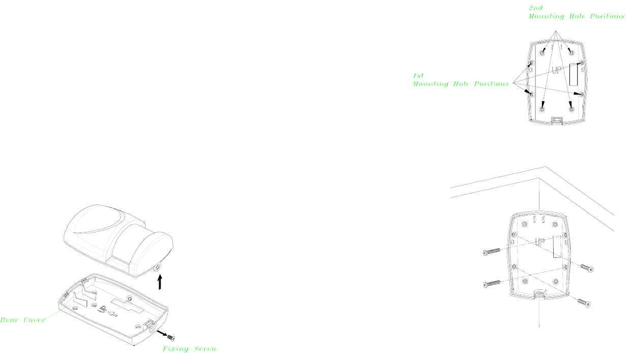
Installation
Ensure that the system is in Test Mode.
1. Undo and re move the fixing scre w from the bottom edge of the detecto r.
Carefully pull the bottom edge of the detecto r away from the rear cove r and
then slide down to release the top clips. (FIGURE 2)
FIGURE 2
2. Carefully drill out the required mounting holes in the rear cover using 3mm drill
according to whether the unit is being mounted in a corner or against a flat wall.
Note: Use 1st group of mounting holes to fulfill corner mounting installation. Use
2nd group of mounting holes for flat wall installation. (FIGURE 3a & 3b)
FIGURE 3a
Corner mounting
FIGURE 3b
3. Using the rear cover as a template, mark the positions of the fixing holes on the
wall.
4. Fix the rear cover to the wall using the two 18mm No .4 screws and 25mm wall
plugs, (a 5mm hole will be required for the wall plugs). Do not over-tighten the
fixing screws as this may distort or damage the cover.
5. Configure the detector as described below. Rememb er that on initia l
installation that the device needs to be tested.

4
6. Check that the detector PCB is located and set in the correct position to provide
the required detection range. To adjust the PCB position, simply slide it up or
down ensuring that the l ocation legs are aligned with the required position
number marked on the board.
7. To refit the detector to the rear cover and locate the clips in the top edge into the
rear cover. Push the lower edge of the detector int o place and refit the fixing
screw in the bottom edg e of the det ector to secure in position. Do not
over-tighten the fixing screws as this may damage the casing.
Settings
Warm-Up
It will take approximately 2 minutes to warm up after battery has been connected.
When the red LED turns on steadily for 5 seconds, it implies warm-up procedure is
completed and the detector is ready for detection.
Test Mode and Operation
1. After power on, PIR will warm-u p for about 2 minu tes. If the unit store s no
node ID then the LED will continuously flash to remi nd the user for inclusion.
Distance test for PIR can only be done after inclusion.
2. Test mode:
After inclusion, if Tamper switch is not pressed, the unit will enter test mode.
When PIR is triggered, the red LED will light up once and retrigger time is about
5 seconds. However , if Tamper switch is pressed, t he unit will enter normal
mode. When PIR is triggered, the red LED will not light up and retrigger time is
based on set up value.
3. By walking into a protected area within coverage of 110 degrees, the detector
will now be triggered e ach time th e detector senses move ment. The
associated appliances wil l be activated. For exa mple, siren will sound or
indication of movement detection will be shown on the controll er. It implies
that the unit is working properly.
Programming
1. Z-Wave’s Group (Association Command Class Version 2)
The unit supports two association groups with one node support for Grouping 1 and
five nodes support for G rouping 2. This has the effect that whe n the un it is
triggered, all devices associated with the unit will receive the relevant reports.
There are two kinds of reports: ALARM_REPORT and
SENSOR_BINARY_REPORT.
1-1 Grouping 1 (Max. node = 1)
1-1-1 Power Applied Command
The unit will send ALA RM_REPORT command to the node s of
Grouping 1 to inform the device that the unit is powered up.
ALARM_REPORT Command:
[Command Class Alarm, Alarm Report, Alarm Level = 0x01,
Alarm Type = 0x02]
1-1-2 Intrusion Event Report (Binary Sensor Report)
Once the Detector detected a movement, the unit will send SENS OR
_ BINARY_REPORT to the nodes of Grouping 1 to inform there is an
intrusion event. Once the movement is sto pped, SENSOR_
BINARY_REPORT will be sent again to the associated devices.
BINARY SENSOR REPORT Command:
Event Present:
[Command Class Sensor Binary, Sensor Binary Report, Value =
255 (0xFF)]
Event Clear:
[Command Class Sensor Binary, Sensor Binary Report, Value =
0 (0x00)]
1-1-3 Low Battery Report (Alarm Report Class)
Upon Detector status being changed, the unit will check its battery
status simultaneously. When the battery level of the unit drops to an
unacceptable level, the unit will emit ALAR M_REPORT command to
the nodes of Grouping 1.
ALARM_REPORT Command:
[Command Class Alarm, Alarm Type = 0x01, Alarm Level =
0x01]
1-1-4 Tamper Event Report
When the tamper switch (link key) is pressed for over 10 seconds and
then released, the unit will emit ALARM_REPO RT command to the

5
nodes of Grouping 1.
ALARM_REPORT Command:
[Command Class Alarm, Alarm Type = 0x03, Alarm Level =
0x01]
1-2 Grouping 2 (Max. node = 5)
1-2-1 Control other Z-Wave Devices
When the detector is triggered, the unit will send BASIC_SET command
which contains a value that is adjust able, to the nodes of Groupi ng 2.
For instance, the brig htness level of a lamp m odule can be fixed
according to the set value.
However, the BASIC_SET command will also be sent to the nodes of
Grouping 2. For inst ance, a lamp module will be turned of f after
receiving the BAISC_SET command.
Basic Set Command:
Event Present:
[Command Class Basic, Basic Set, Value = 255
(
0xFF
)
]
Event Clear:
[Command Class Basic, Basic Set, Value = 0
(
0x00
)
]
2. Z-Wave’s Configuration
The following information is for someone that has some experience in setting up a
Z-Wave system or some one that h as computer software running a Z-Wave
controller. Please get familiar with software of Z-W ave controller before gettin g
started.
To save po wer consumption for the ba ttery, RF po wer of HSP02 is in of f mode
ordinarily. Please pre ss Tamper switch once to turn on the RF power for 30
seconds in o rder to st art function set up, and the user can see the LED st arts
flashing. If set up is not finished within 30 seconds, press Tamper switch o nce
more to continue the set up (or press Tamper switch 3 times within 1.5 seconds, and
the unit will stay “awake” for 10 minutes).
2-1 Basic Set Level
When Basic Set Command is sent where contains a value, the receive r will
take it for consideration; for instance, if a lamp module receives the Basic Set
command then the carried value will set the dim level of the lamp module.
Example:
0 : OFF
1-99, 0xFF: ON (Binary Switch Device)
Dim Level (Multilevel Switch Device)
Function Parameter Numbe
r
Size Range Default
Basic Set level 1 1 1 ~99,
0xFF
0xFF
Configuration Command
2-2 Enabling/Disabling Sensor Detecting Function
Sensor function Enable/Disable: To start or stop the sensor functions
Note 1 Sensor includes PIR Sensor & Light Sensor
Note 2 Default for HSP02 is Enable, when power applied, the unit is at
Enable status
Configuration Command
Function Parameter
Number Size Range Default
Group1/Group2
Enable/Disable 2 1
0=Group1 Disable
Group2 Disable
1=Group1 Enable
Group2 Enable 1 ( Enable)
2=Group1 Enable
Group2 Disable
3=Group1 Disable
Group2 Enable
2-3 Sensitivity Level (PIR sensor only)
In order to provide a best efficiency of the detector, it is recommended to test
the detector with movements from a farthest end of the cove rage area at first
time of use. If movements cannot be detected sensitively, simply adjust the
sensitivity level with Con figuration Parameter #3. This parameter can be
configured with the value of 1 through 10, where 1 means low sensitivity and
10 means highest sensitivity.
Function Parameter Numbe
r
Size Range Default
Sensitivity Level 3 1 1~10 6
Configuration Command
6
2-4 Re-trigger Interval Setting (PIR sensor only)
The Configuration parameter that can b e used to adj ust the interval of being
re-triggered after the detector has been triggered as Configuration Parameter
#4. No response will be made during this interval if a movement is presented.
The time interval can be set between 5 secs to 3600 secs.
Function Parameter Numbe
r
Size Range Default
Re-trigger Interval 4 1 or
2 (if value > 127)
5~3600
(sec)
180
2-5 Lux Level
The user can set a d etecting percentage of lux level which determines when
the light se nsor will be activated. If percent age of lux level of ambient
illumination falls below this percentage, and a person moves across or within
the protected area, the detector will emit Z-Wave ON Command (i.e. Basic Set
Command (Value = Basi c Set Level)) to controlle r and activate con nected
modules and lighting. Percentage can be set from 1% to 100%.
Function Parameter Numbe
r
Size Range Default
Lux Level 5 1 1~100 % 10%
Configuration Command
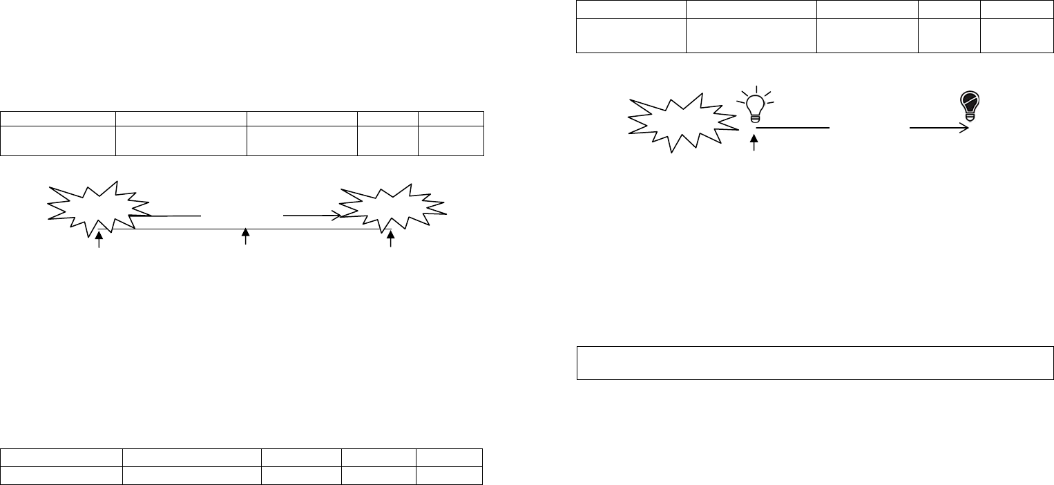
2-6 On-Off Duration
The function of on-off duration setting will be useful if the detector is connected
with a mo dule or lig hting. The duration determines how long th e
module/lighting should stay ON. For instance, a value of 100 means the
Lamp Module will turn off 100 seconds later after it turns on. This parameter
can be configured from 5 to 3600, where the value means how many seconds
of delay.
Function Parameter Numbe
r
Size Range Default
On-Off Duration 6 1 or
2 (if value > 127)
5~3600
(sec.)
15
Configuration Command
3. Advanced Programming
3-1 Battery Check Command
The users can also en quire the battery status of the Dete ctor by se nding
BATTERY_ GET command via Z-W ave Controller. Once the unit receive s
the command, it will return BA TTERY_REPORT command. If the unit i s in
low battery status, a Battery_Level = 255 (0xFF) command will be sent to the
Z-Wave Controller.
BATTERY_REPORT Command
[Command Class Battery, Battery Report, Battery Level = 20%-100%]
3-2 Wakeup Command Class
The detector stays in sleep status for the majority of time in order to conserve
battery life. However, it can be woken up by either triggers of movement or
by setting WAKE_UP_INTERVAL_SET command via Z-W ave Controller.
After the unit wakes up, it will send Wakeup Notification Command to the node
ID that requires to be reported. The minimum and maximum wakeup interval is
60 seconds and 194 days respectively. Allowable interval among each wakeup
interval is 1 second, such as 60, 61, 62 ….
Note: The default value is 1 day, which implies that the detector awakes and
sends the Wakeup Notification Command to the set node every day.
Command Classes
The Motion Detector supports Command Classes including…
* COMMAND_CLASS_ALARM
Detected a
movement
15 seconds
Detector is
triggered
Light
turns on Light
turns off
180 seconds
Detected a
movement
Detected a
movement
Detected a
movement
(no response)
Triggere
Triggered

7
* COMMAND_CLASS_BATTERY
* COMMAND_CLASS_VERSION
* COMMAND_CLASS_WAKE_UP_V2
* COMMAND_CLASS_ASSOCIATION_V2
* COMMAND_CLASS_CONFIGURATION
* COMMAND_CLASS_SENSOR_BINARY
* COMMAND_CLASS_MANUFACTURER_SPECIFIC
---For Control Other Devices---
* COMMAND_CLASS_BASIC
Troubleshooting
Symptom Possible Cause Recommendation
LED cannot be displayed Run out of battery
power
Replace a new battery
Check if reverse battery
polarity
Refit the battery with
correct polarity
The detector not working Check if mounting
location is proper
Reposition its mounting
location
Remove the source of
interference
Check if the detector is
out of order
Do not open the detector;
send it to the local retailer.
Two minutes warm up is
completed, The detector
does not work and LED
flashes on & off repeatedly
at 2-second intervals
Check if detector is first
power up or the
detector has executed
exclusion or reset
procedure
Please carry out inclusion
procedure; make sure
there are ID codes stored
in the detector.
Specifications
Battery CR2 3.0V 900mAh Lithium Battery
Operating Range Minimum 30 meters (free space)
Warm Up Time About 2 minutes
PIR Detection Coverage Wall-Mounted:
Up to 10m x 110° (at 1.8m mounting height & 25°C)
Operating Frequency 908.42 MHz (US) / 869 MHz (RU)
FCC ID FU5HSP02
*Specifications are subject to change without notice
A501112129R 2013/09
Federal Communication Commission Interference Statement
This equipment has b een tested and found to comp ly with the limits for a Cl ass B digital
device, pursuant to Part 15 of the FCC Rules. These limits are design ed to pro vide
reasonable protection against harmful interference in a residential installation. T his
equipment generates, uses and can radiate radio frequency energy and, if not installed and
used in acc ordance with the instructio ns, may cause harmful inter ference to ra dio
communications. Ho wever, there is no g uarantee that interfere nce will not occur in a
particular installation. If this eq uipment does cause harmful interference to r adio or
television reception, which can be determined by turning the equipment off and on, the u ser
is encouraged to try to correct the interference by one of the following measures:
- Reorient or relocate the receiving antenna.
- Increase the separation between the equipment and receiver.
- Connect the equipment into an outlet on a circuit different from that to which the receiver
is connected.
- Consult the dealer or an experienced radio/TV technician for help.
This device complies with Part 15 of the FCC Rules. Operation is subject to the following two
conditions: (1) This device may not cause harmful interference, and ( 2) this device must
accept any interference received, including interference that may cause undesired operation.
FCC Caution: Any changes or modifications not expressly approved by the party responsible
for compliance could void the user's authority to operate this equipment.
This transmitter must not be co-located or operating in conjunction with any other antenna or
transmitter.
WARNING:
Do not dispose of electrical appliances as unsorted municipal waste, use separate
collection facilities.
Contact your local govern ment for inform ation regarding the coll ection systems
available.
If electrical appliances are disposed of in landfills or dumps, hazardous substances
can leak into the groundwater and get into the food chai n, damaging your health
and well-being.
When replacing old appliances with new ones, the retailer is legally obligated to take
back your old appliance for disposal at least for free of charge.