Everspring Industry Co SA823 U-net Repeater User Manual SA823 0529 2017 1 FCC
Everspring Industry Co Ltd U-net Repeater SA823 0529 2017 1 FCC
UserManual.wiki
>
Everspring Industry Co
>
SA823 User Manual
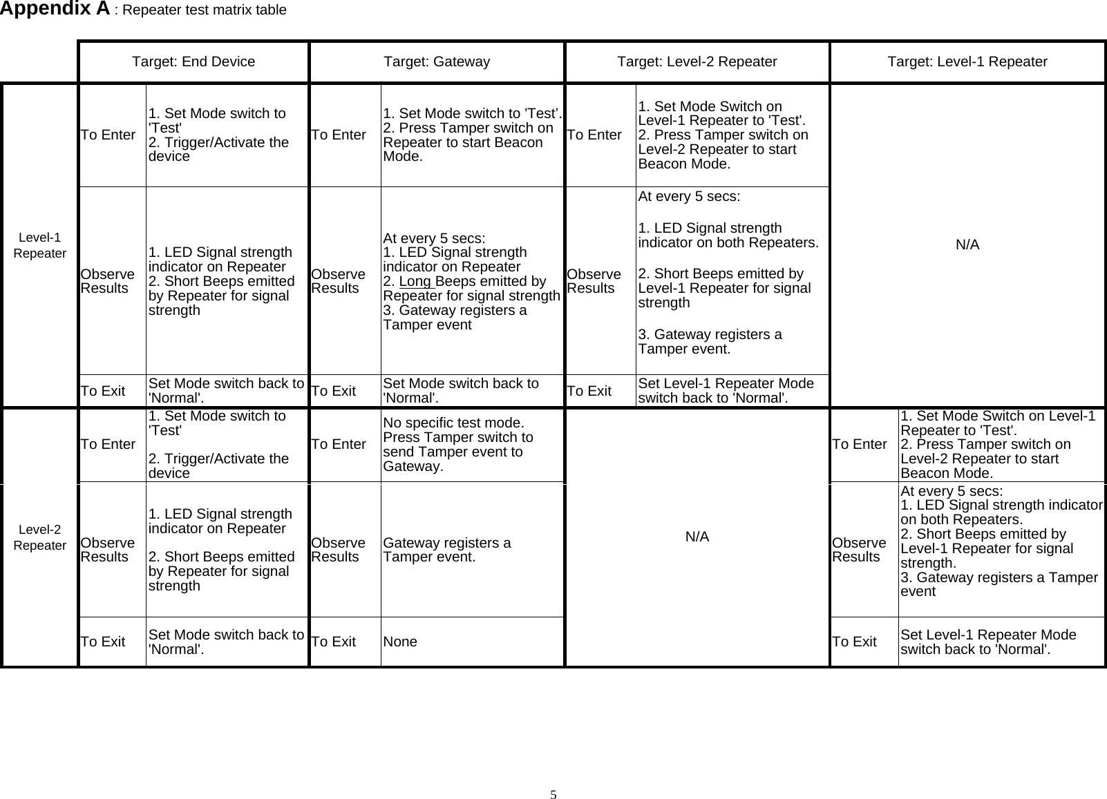
User manual
Navigation menu
Upload a User Manual
Namespaces
Wiki Guide
HTML
PDF
Info
Views
User Manual
Discussion / Help
Navigation