Everspring Industry Co SA823 U-net Repeater User Manual SA823 0529 2017 1 FCC
Everspring Industry Co Ltd U-net Repeater SA823 0529 2017 1 FCC
User manual
1
SA823 U-NET REPEATER
The SA823 is a signal repeater to extend the range of U-Net two-way wireless technology. It is fully
compatible with any U-Net enabled sensors and controller.
The signal repeater is designed to be installed by a system installer in cases where signal reception is
poor or extended range is required for the home. The repeater does not alter the existing binding
network between gateway and devices, in fact devices do not need to be physically removed from their
mounting location when adding the repeater. This allows the installer to service the user in the shortest
time possible without disrupting to the home interior.
It comes with installer friendly feature such test mode to indicate signal strength using LED display and
audible beeps for areas not in line of sight such as corners. Powered by backup battery, this allows the
repeater to be easily placed anywhere while searching for its optimum location. There is the also a
Beacon mode which allows the installer to conveniently walk around the home to observe signal
strengths from the gateway when deciding on the best location.
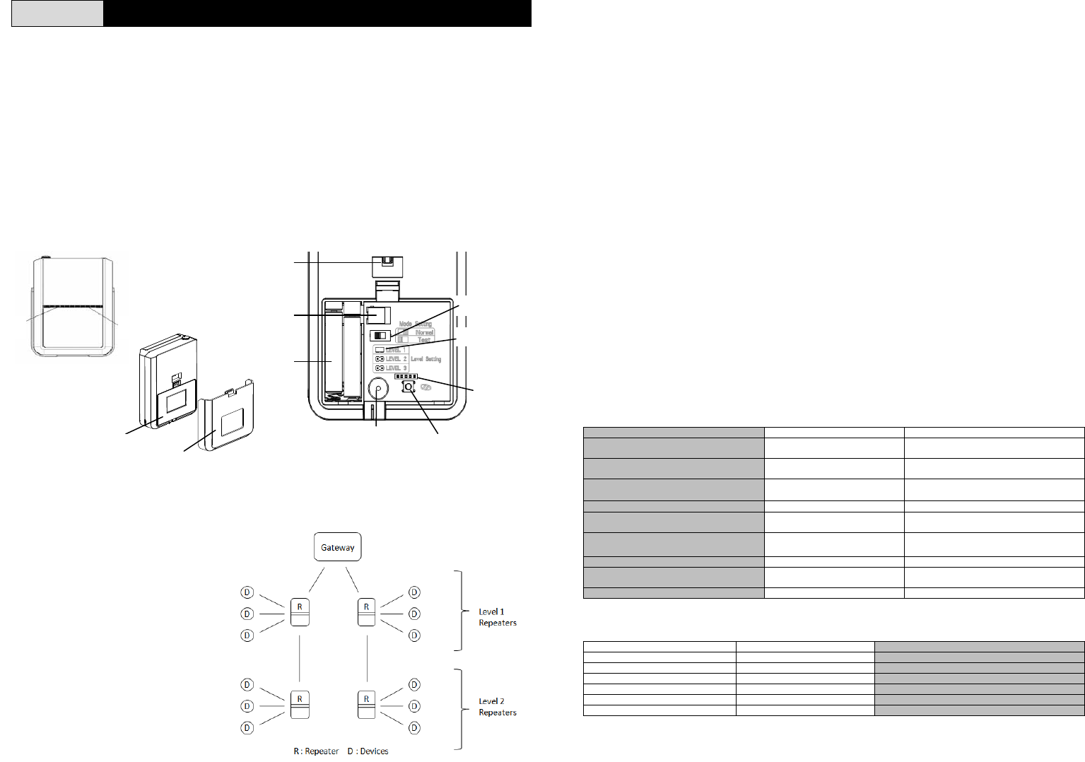
Product Overview
Front View
View with Battery Cover removed
Repeater network overview
The role of the Repeater in a U-Net network can be summarized in the diagram below.
Level :
Repeaters are distinguished into Level-1
and Level-2 as set by their Level jumper
setting. Each pair of Level-1 and 2
repeaters define a unique signal path to
the gateway. Signals from each pair will
not cross over to another pair.
- Level-1: Repeater closest to the gateway. In most cases adding a Level-1 Repeater is sufficient to
cover a wide range. A gateway can have more than one Level-1 Repeaters to branch out at different
angles from the gateway.
- Level-2: Repeater to extend signal from Level-1 Repeater. Only one Level-2 repeater can be added for
each Level-1 Repeater.
To create the link between the pairs, repeaters must perform U-net binding with each other. Repeaters
with the same level cannot bind with each other.
Lastly, like all end devices under the gateway’s network, each repeater must perform U-net binding with
the gateway. This ensures the gateway is aware of the repeater’s own condition such as low battery,
tamper, etc.
Note: It is advisable to use as few Repeaters as possible in a network in order to reduce signal hops
between device and Gateway. Like any wireless network, more signal hops not only mean longer delay
in transmission but also adds higher risk of signal interference resulting in lost messages as more
devices are added. This degrades the overall network quality.
Join:
The repeater becomes associated with an end device through ‘Joining’. This is a loose form of binding
that tells a repeater which devices it should repeat signals for and which do not. Joining is a manual
process similar to U-net binding except there is no need to remove end devices from their mounting
position to activate a learn key. Simply trigger the end device for it to transmit its ID which is then picked
up by the repeater. Joining does not disrupt the original U-net binding between end devices with
gateway.
Inversely, a device is disassociated from the Repeater through ‘Un-join’. Removing a device from the
Repeater’s memory helps to reduce unnecessary transmission of RF signal which will improve overall
quality of the network.
LED Table
The table below describes the LED indication at various stages of the unit’s operation.
Pairing stage:
During the Repeater’s pairing activity, Status LED along with the buzzer beeps indicate the status of the
paring.
Status Status LED Buzzer Beep
Factory reset state. Repeater not
p
aired to an
y
Gatewa
y
.After power up, Blinks RED
ever
y
2 secs for 30 secs. None
Enter pairing mode Steady RED Short beeps every 1 sec, followed by
1 lon
g
beep
Waiting to bind with gateway, time out
in 30 secs. Blink RED, every 1 sec Short beeps every 1 sec
Pairing successful LED OFF 1 Long beep
Pairing fail after time out or
terminated Flashes RED 3 times Short beep 3 times
Joining fail because exceed device
limit On RED for 1 sec then OFF 3 short beeps
Device Un-
j
oin successful LED OFF 2 Lon
g
beep
Level-2 Repeater disconnected
successful LED OFF 2 Long beep
Activate Factor
y
Reset Stead
y
RED Short beeps, followed b
y
1 lon
g
beep
Testing stage (Mode switch set to TEST)
During Test mode, RF LED and the buzzer beeps indicate the signal strength.
RF LED
–
Test Mode Buzzer beep sound Description
Flash GREEN 3 times Short beep 3 times Signal is Good, Test mode
Flash ORANGE 2 times Short bee
p
2 times Si
g
nal is Normal, Test mode
Flash RED 1 time Short bee
p
1 time Si
g
nal is Weak, Test mode
Flash GREEN 3 times Lon
g
bee
p
3 times Si
g
nal is Good, Beacon mode
Flash ORANGE 2 times Long beep 2 times Signal is Normal, Beacon mode
Flash RED 1 time Lon
g
beep 1 time Si
g
nal is Weak, Beacon mode
RF Stat
Batt Wall
Rear View
Back
DC
Mode Switch
Tamp
Buzze
r
Factory
Level Jumpe
r
Learn Button
2
Status LED
–
Test Mode Description
Flashes ORANGE, every 1 sec Test mode activated
Normal usage (Mode switch set to NORMAL):
Once the Repeater is installed and set for daily use, the LED display becomes as follows:
Status LED
–
Daily usage Explanation
Stead
y
GREEN Powered b
y
AC power, Normal mode
Flashes GREEN, ever
y
30 secs. Powered b
y
backup batter
y
, Normal mode
Flashes RED, ever
y
30 secs. Backup batter
y
is low
Flashes ORANGE, ever
y
30 secs. Powered b
y
AC but detected backup batter
y
is low
RF LED
–
Dail
y
usa
g
e Explanation
Flash GREEN Si
g
nal received, Normal mode
Flash RED Repeater Tamper switch activated
Binding With Gateway
The Repeater supports Auto-Binding feature where it will automatically enter binding mode when first
powered up after a factory reset.
1. Remove the wall bracket by pushing it downwards and then remove the battery cover.
2. Prepare three AA 1.5V batteries. Do not insert them into the unit yet.
3. Ensure the Level jumper in the Repeater is set to Level-1.
4. Set a U-net compatible gateway into binding mode. Usually this is achieved by pressing the Link
button on the gateway.
5. Insert the batteries with correct polarity at this point. Within a few seconds a long beep sound will
be heard indicating the pairing is complete.
6. Time-out will occur if the binding process was unsuccessful, indicated by 3 short beeps. If this
happens, refer to the Manual Binding procedure in the Troubleshooting section.
Note: A Repeater must reset back to factory default before it can pair with another gateway. See the
Factory Reset section in the Troubleshooting section.
Adding a Device (Join process)
1. Put repeater into Joining mode by pressing the learn button until 3 beeps is over and release.
Repeater will enter learning mode for 30 secs.
2. Bring the repeater in close range to the device, around ~10cm.
3. Simply trigger the device (PIR trigger, door sensor open, etc.) to emit a signal which will be picked
up by the Repeater.
Note:
- Unlike binding, there is no need to press learn key on device.
- Refer to the LED Table for details of pairing indicators.
4. Once the signal is picked up by the Repeater, it will emit one long beep sound. Joining process is
complete. From now on Repeater will start routing signal for this device.
5. Time-out will occur if the Joining process is unsuccessful, indicated by 3 short beeps.
Note: PIR motion sensors will have a retrigger interval or sleep period which lasts longer than the
Repeater’s 30 secs Join period. If time out occurs, try again when the PIR is ready. If necessary,
cover the PIR with a dark cloth when preparing the Repeater.
6. Repeat the steps above for other devices.
Note :
- Each Repeater supports a maximum of 8 devices.
- Keypad and Siren devices are NOT supported by this Repeater.
- Remote keyfobs do not need to Join to any Repeater. All Repeaters will retransmit signals from
Remote Keyfobs in the same network.
- A Repeater will Join only devices from the same gateway paired to the Repeater
- A device can Join to only one Repeater at any one time. If the device needs to Join to another
Repeater, it must first Un-Join from the first Repeater. The Un-Join procedure is similar to Join
procedure except two beeps will be heard when completed.
- If any device is deleted by the gateway, the gateway will inform the Repeater to Un-Join this device
from its memory.
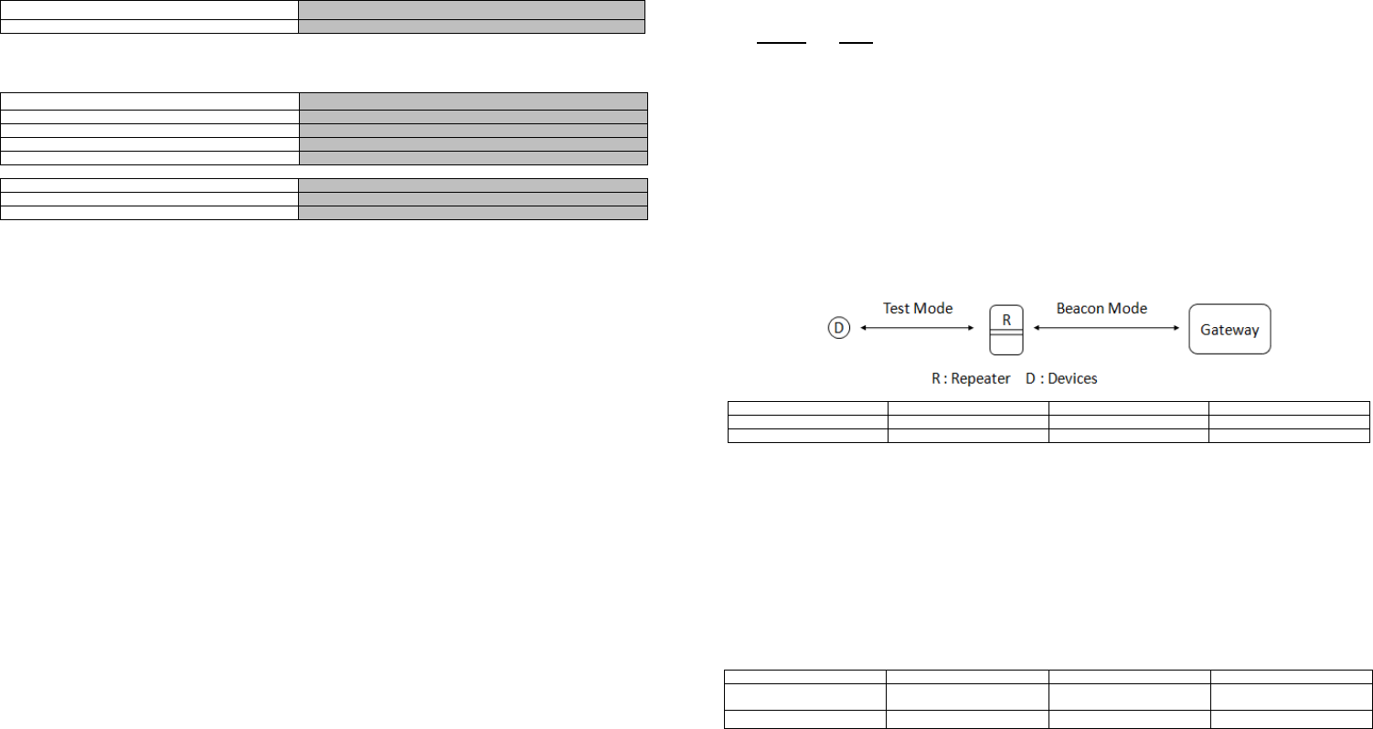
Testing
There are two signal test methods provided by the Repeater;
- Test Mode : this tests the signal between the end device to Repeater
- Beacon Mode : this tests the signal between the Repeater to Gateway. It is also used to test signal
between Repeaters.
Good Normal Wea
k
RF LED Flash Green 3 times Flash Oran
g
e 2 times Flash Red 1 time
Beep sound* 3 lon
g
beeps 2 lon
g
beeps 1 lon
g
beep
Test Mode
This is used when searching for a good spot to mount the Repeater. In this mode the unit will indicate
signal strength for each signal sent by the device.
1. Join a device to the Repeater as described above.
2. Set the Mode switch to Test mode.
3. Place the Repeater at a distance away from the end device.
4. Trigger the device, e.g. open a door sensor or press the on/off button on a smart plug. The
Repeater will indicate the received signal strength as follows:
Good Normal Wea
k
RF LED Flash Green 3 times Flash Orange 2 times Flash Red
1 time
Beep sound 3 short beeps 2 short beeps 1 short beep
5. Set the Mode switch back to Normal mode to exit.
Beacon Mode
In this mode the Repeater transmits a ping signal to the gateway at every 5 secs interval. The reply
signal from the gateway is then measured for strength and indicated by RF LED and buzzer beeps. This
feature allows the installer to walk around the premises while observing the signal quality at the spot.
This is useful for;
- identifying weak areas for placing a sensor
- testing signal strength between Repeater and Gateway before mounting it permanently
- testing the signal strength between Repeater pairs when adding a second Repeater.
To use Beacon mode with a Gateway;
1. Set the Mode switch to Test mode.
3
2. Press the Tamper switch on the Repeater. The ping signal will be sent every 5 secs. The
Repeater will indicate the received signal strength as follows:
*same as Test Mode but long beeps instead of short beeps
3. Set the Mode switch back to Normal mode to exit.
A matrix summary of the Test Mode and Beacon Mode can found in Appendix A.
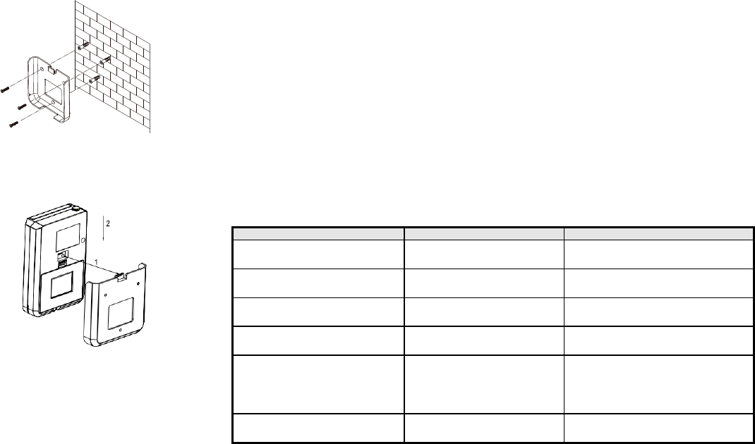
Mounting the Repeater
A clean smooth surface is required to securely mount the Repeater. The unit should be placed on the
wall, at least 1.5m high from floor, for improved reception.
1. Use the wall bracket as a template to mark and drill the
position of 3 mounting holes on the wall.
2. Fix the wall bracket to the wall using the plastic wall plugs and fixing screws provided.
3. Connect the DC adaptor to DC jack of the unit and place the battery cover over the battery
compartment.
Note : the unit should always be powered DC adaptor instead of its backup battery.
4. Slide the unit down into its wall bracket ensuring the tamper
switch is pressed by the wall bracket as shown below.
Tamper Protection
Tamper protection is activated when the tamper switch is pressed
continuously for more than 2 minutes. Removing the unit from its wall bracket will release the tamper
switch and generate a full alarm condition.
Maintenance
1. The unit reports its presence to the gateway every 60 minutes. This way the gateway will be
alerted if the Repeater becomes missing.
2. Low Battery: When its backup battery becomes low, the unit will report back to the gateway and
the Status LED will flash every 30secs. Replace the battery the soonest possible to keep the unit
operating during a power cut.
Level-2 Repeater
Connecting a Level-2 Repeater
This follows the same procedure as binding to a Gateway.
1. Firstly, bind the second Repeater to the Gateway as in the section Binding with Gateway.
2. Once completed, setting its Level jumper to Level-2.
3. Set the unit into pairing mode by press and holding its Learn button for 3 secs until a long beep
sound is heard, then release the button. The unit is now ready to pair for 30 secs.
4. Within 30 secs, set Level-1 Repeater into pairing mode also by performing the previous step
above.
5. Soon both units will emit a long beep indicating both are now connected to each other. Refer to
the LED Table for details of pairing indicators.
Disconnecting a Level-2 Repeater
1. Set the Level-1 Repeater into pairing mode by press and holding its Learn button for 3 secs until a
long beep is heard, then release the button.
2. Within 30 secs, bring the Level-2 Repeater in close range to Level-1 Repeater, around ~10cm
and press the Tamper switch on the Level-2 Repeater.
3. 2 long beeps will be heard on Level-1 Repeater indicating both are now disconnected from each
other.
Note:
- Level-2 will still preserve all the Join devices in its memory. It will continue to serve these devices
even after connecting to a new Repeater or directly to Gateway. Only by doing a Factory reset will all
the Join devices be erased from the Repeater’s memory.
- Level 3 jumper is for factory use only.
Troubleshooting
The troubleshooting table lists some possible causes and solutions
S
y
mptom Cause of Failure Recommendation
Binding with Gateway does not work. The Repeater has previously been
paired with another
g
atewa
y
Perform factory reset on the Repeater.
Remote keyfob cannot Join to
Repeater. Remote keyfob does not require
Join procedure None. All the Repeaters in the network
will transmit si
g
nals from remote ke
y
fob
Keypad and Siren cannot Join to
Repeater. Keypad and Siren are not
supported. Keep keypad or siren within range of the
Gatewa
y
Repeater keeps beeping whenever a
si
g
nal is received. Repeater set to Test Mode Switch Mode jumper to Normal Mode.
Repeater is added but still cannot
achieve desired range. 1. Range is too far.
2. Signal is blocked by thick wall.
1. Set the Repeater to Level-2 and add a
Level-1 Repeater in between to extend
range.
2. Place Repeater near openings in the
wall such as a door or window.
Cannot pair a second Repeater to
first Re
p
eate
r
Both Repeaters are set to the
same Level Set one of them to a different Level using
the Level
j
um
p
er.
Manual Binding
1. Set the unit into pairing mode by pressing and holding its Learn button for 3 secs until a long beep
sound is heard, then release the button. The unit is now ready to pair for 30 secs.
2. Set a U-net compatible gateway into binding mode. Usually this is achieved by pressing the Link
button on the gateway.
3. Within 5 secs the unit will emit a long beep indicating the binding procedure is complete. Refer to
the LED Table for details of pairing indicators.
4
Reset To Factory Default
To reset the unit back to factory default state:
1. Press and hold the Learn button for 3 secs until a long beep sound is heard, then release the
button.
2. Within 30 secs, press and hold the Learn button again but this time for more than 6 secs until
another long beep sound is heard. This indicates the reset is complete. The LED will blink every 2
secs indicating no paired ID code is stored its memory.
Specification
O
p
eratin
g
tem
p
erature ran
g
e0°C to +50°C
O
p
eratin
g
humidit
y
1
0
-
85% R
H
Power suppl
y
I/P: 10
0
-
240Vac 50/60Hz 0.5A
O/P: DC9V 2000mA
Backu
p
batter
y
1.5V
A
A
A
batteries x
3
Batter
y
life Between 24~48 hrs
Frequenc
y
ran
g
e 868MHz
(
EU
)
/ 923MHz
(
America
)
** Specifications are subject to change without notice.
Federal Communication Commission Interference Statement
This equipment has been tested and found to comply with the limits for a Class B digital device, pursuant to Part 15 of
the FCC Rules. These limits are designed to provide reasonable protection against harmful interference in a
residential installation. This equipment generates, uses and can radiate radio frequency energy and, if not installed
and used in accordance with the instructions, may cause harmful interference to radio communications. However,
there is no guarantee that interference will not occur in a particular installation. If this equipment does cause harmful
interference to radio or television reception, which can be determined by turning the equipment off and on, the user is
encouraged to try to correct the interference by one of the following measures:
- Reorient or relocate the receiving antenna.
- Increase the separation between the equipment and receiver.
- Connect the equipment into an outlet on a circuit different from that to which the receiver is connected.
- Consult the dealer or an experienced radio/TV technician for help.
This device complies with Part 15 of the FCC Rules. Operation is subject to the following two conditions: (1) This device
may not cause harmful interference, and (2) this device must accept any interference received, including interference
that may cause undesired operation.
FCC Caution: Any changes or modifications not expressly approved by the party responsible for compliance could void
the user's authority to operate this equipment.
RF exposure warning
This equipment must be installed and operated in accordance with provided instructions and the antenna(s) used
for this transmitter must be installed to provide a separation distance of at least 20 cm from all persons and must not be
co-located or operating in conjunction with any other antenna or transmitter. End-users and installers must be provide
with antenna installation instructions and transmitter operating conditions for satisfying RF exposure compliance
WARNING:
Do not dispose of electrical appliances as unsorted municipal waste, use separate collection facilities.
Contact your local government for information regarding the collection systems available.
If electrical appliances are disposed of in landfills or dumps, hazardous substances can leak into the groundwater and
get into the food chain, damaging your health and well-being.
When replacing old appliances with new ones, the retailer is legally obligated to take back your old appliance for
disposal at least for free of charge.
www.everspring.com
50 Sect. 1 Zhonghua Rd Tucheng
NewTaipeiCity 236 Taiwan..

5
Appendix A : Repeater test matrix table
Target: End Device Target: Gateway Target: Level-2 Repeater Target: Level-1 Repeater
Level-1
Repeater
To Enter
1. Set Mode switch to
'Test'
2. Trigger/Activate the
device
To Enter
1. Set Mode switch to 'Test’.
2. Press Tamper switch on
Repeater to start Beacon
Mode.
To Enter
1. Set Mode Switch on
Level-1 Repeater to 'Test'.
2. Press Tamper switch on
Level-2 Repeater to start
Beacon Mode.
N/A
Observe
Results
1. LED Signal strength
indicator on Repeater
2. Short Beeps emitted
by Repeater for signal
strength
Observe
Results
At every 5 secs:
1. LED Signal strength
indicator on Repeater
2. Long Beeps emitted by
Repeater for signal strength
3. Gateway registers a
Tamper event
Observe
Results
A
t every 5 secs:
1. LED Signal strength
indicator on both Repeaters.
2. Short Beeps emitted by
Level-1 Repeater for signal
strength
3. Gateway registers a
Tamper event.
To Exit Set Mode switch back to
'Normal'. To Exit Set Mode switch back to
'Normal'. To Exit Set Level-1 Repeater Mode
switch back to 'Normal'.
Level-2
Repeater
To Enter
1. Set Mode switch to
'Test'
2. Trigger/Activate the
device
To Enter
No specific test mode.
Press Tamper switch to
send Tamper event to
Gateway.
N/A
To Enter
1. Set Mode Switch on Level-1
Repeater to 'Test'.
2. Press Tamper switch on
Level-2 Repeater to start
Beacon Mode.
Observe
Results
1. LED Signal strength
indicator on Repeater
2. Short Beeps emitted
by Repeater for signal
strength
Observe
Results Gateway registers a
Tamper event. Observe
Results
A
t every 5 secs:
1. LED Signal strength indicator
on both Repeaters.
2. Short Beeps emitted by
Level-1 Repeater for signal
strength.
3. Gateway registers a Tamper
event
To Exit Set Mode switch back to
'Normal'. To Exit None To Exit Set Level-1 Repeater Mode
switch back to 'Normal'.