Everspring Industry Co SR102 PIR Sensor Lantern Transmitter User Manual
Everspring Industry Co Ltd PIR Sensor Lantern Transmitter
Users Manual
1
SR102 REMOTE TRANSMITTER
The Remote Transmitter is designed to control a series of O-net products, such
as EZ Alarm (SE131), On/Off Receiver (AN121, B410N) and Dimmer Receiver
(AD121, B410D), serving as a multipurpose remote controller. It is equipped with
7 sets of ID codes, therefore, each set of them is capable of controlling limitless
receivers.
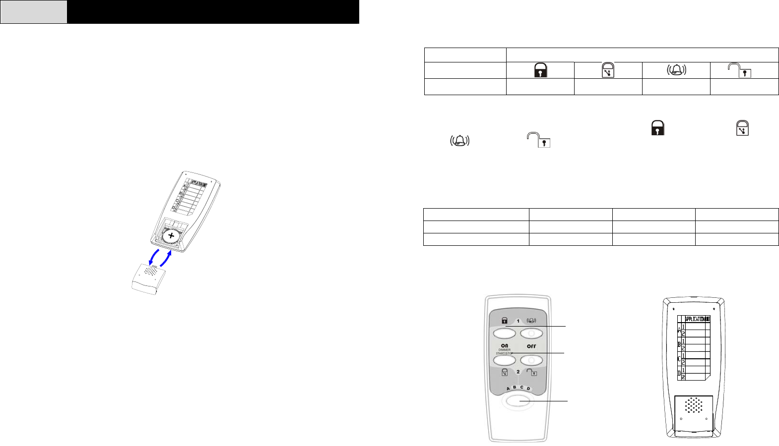
LOADING THE BATTERY
1. Remove the battery cover. Fit the 3V Lithium battery in the compartment
provided with +v terminal facing upwardly. (Fig. 1)
Fig. 1
2. By pressing any key, the red LED will illuminate, which implies that the
battery has been inserted properly.
3. Replace the battery cover.
SETTING THE HOUSE CODE
The Transmitter incorporates 4 buttons and a 4-position house code slide switch.
The 4-position house code slide switch ranges from A to D. (Fig. 2) When
controlling EZ alarm (SE131), the house code slide switch has to be set in “A”
position, while “B”, “C” and “D” positions are designed for use with On/Off
Receiver (AN121, B410N), Dimmer Receiver (AD121, B410D), Lantern Receiver
(ED102) and forthcoming O-net series products.
4-position house code slide switch coupled with 4 buttons may formulate 7 sets of
ID codes, every of which is controllable to numerous receivers.
1. Setting the house code slide switch to “A” can operate EZ alarm (SE131).
House Code Position “A”
Button
No. of ID ID1 ID1 ID1 ID1
When switching to the “A” position which is situated in the orange background of
plate, simply follow its orange track for operating (instant arm), (delay
arm), (chime) and (disarm) modes.
2. Setting the house code slide switch to “B”, “C” or “D” position can take control
of On/Off Receiver (AN121, B410N), Dimmer Receiver (AD121, B410D) and
Lantern Receiver (ED102).
House Code Position “B” “C” “D”
1st. set of On, Off button ID2 ID4 ID6
2nd set of On, Off button ID3 ID5 ID7
4 buttons are divided into two sets, consisting of one pc each of On and Off
button. (Fig. 2)
Fig. 2 Fig. 3
Note: Write down each designated lighting fixture in each group by adopting the
sticker affixed on the rear cover. (Fig. 3)
1st. set
2n
d
. set
House
code
slide
switch
2
EMITTING THE ID CODE
In order to communicate with the EZ Alarm (SE131), ON/OFF Receiver
(AN121,B410N) and Dimmer Receiver (AD121,B410D), it is essential that the
same ID code is used between the Receiver and Transmitter.
Set the Receiver to the ID code learning mode. Press and hold the “OFF or
button” on the Remote for 3 seconds until the LED extinguishes will emit the ID
code to the receivers, subject to house code slide switch being set at the right
position as mentioned below. The procedure of learning the ID code by the
Receiver is clearly described on the Receiver’s manual.
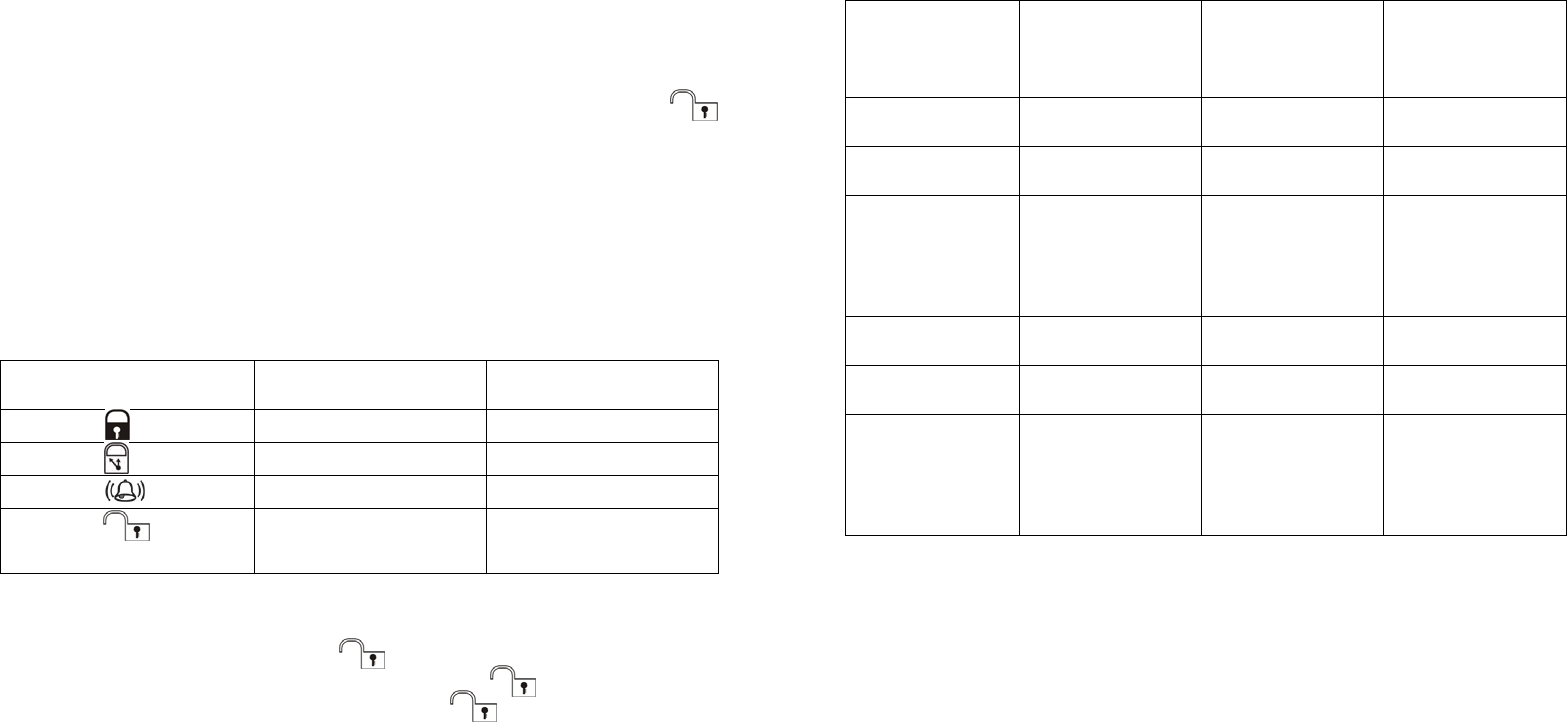
OPERATION
1. To work with the EZ Alarm (SE131), set House code slide switch to the “A”
position:
Remote’s operating status Remote’s RF
transmission EZ Alarm operating
status
Press the button Instant arm Instant
Press the button Delay arm Delay
Press the button Chime Chime
Press the button Disarm/Learn (press
and hold for 3 seconds)
Off/Learn
a. The LED will illuminate each time the button is pressed.
b. The length of time to press the button may decide what kind of RF
signal will be sent to the Receivers. Press the button, an off radio
signal will be emitted. Press and hold the button for more than 3
seconds until the LED extinguishes, a code learning command will be
transmitted.
2. To be compatible with On/Off Receiver (AN121, B410N), Dimmer Receiver
(AD121, B410D) and Lantern Receiver (ED102), set the house code slide
switch to “B”, “C” or “D” position.
Remote’s
operating status Remote’s RF
transmission On/Off Receiver’s
(AN121, B410N)
Operating status
Dimmer
Receiver’s
(AD121, B410D)
operating status
Press 1st. set of
On button On On Dimmer On,
Start/Stop
Press 1st. set of
Off button Off/Learn Off Dimmer Off
Press 1st. set of
On & Off button
simultaneously
for more than 3
seconds
Lock Lock compulsorily
(refer to ”a” as
mentioned below)
Lock compulsorily
(refer to “a” as
mentioned below)
Press 2nd. set of
On button On On Dimmer On,
Start/Stop
Press 2nd. set of
Off button Off/Learn Off Dimmer Off
Press 2nd. set of
On & Off button
simultaneously
for more than 3
seconds
Lock Lock compulsorily
(refer to “a“ as
mentioned below)
Lock compulsorily
(refer to “a” as
mentioned below)
a. Lock compulsorily
Pressing 1st. set of On & Off button simultaneously for more than 3 seconds
will emit lock command to On/Off Receiver/Dimmer Receiver which will stop
receiving signal from any other devices. However, lock command can be
released by pressing “on” button on the Remote Transmitter or pressing the
ON/OFF knob on the On/Off Receiver/Dimmer Receiver directly.
b. Pressing the “OFF” button will emit off signal to turn off the lighting fixture
connected to the On/Off Receiver (AN121, B410N) or Dimmer Receiver
(AD121, B410D), whereas the code learning command will be transmitted by
pressing the “OFF” button for more than 3 seconds until the LED
extinguishes.
3
TROUBLESHOOTING
Symptom Recommendation
Press button, LED not illuminating 1. Reverse battery polarity
2. Run out of battery
No response with the Receiver 1. Check if learning the ID code has
been processed
2. Check if the procedure of ID code
learning is correct
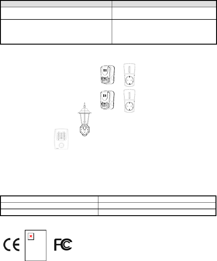
IMPORTANT: It is compatible with the following receivers of our O-net series
products, serving as a transmitter.
On/Off Receiver (B410N, AN121)
Dimmer Receiver (B410D, AD121,)
Lantern Receiver (ED102)
EZ Alarm (SE131)
The member of O-NET series is on the increase. Visit our website
www.everspring.com for update information.
SPECIFICATION
Battery Type CR2032 3V x 1 pc
Transmitting Range 30 meters min. (in an open space)
Frequency Range 315 MHz or 433 MHz
**Specifications subject to change and improvement without notice. A501110439R01
Mobile of end product
Federal Communication Commission Interference Statement
This equipment has been tested and found to comply with the limits for a
Class B digital device, pursuant to Part 15 of the FCC Rules. These
limits are designed to provide reasonable protection against harmful
interference in a residential installation. This equipment generates, uses
and can radiate radio frequency energy and, if not installed and used in
accordance with the instructions, may cause harmful interference to radio
communications. However, there is no guarantee that interference will
not occur in a particular installation. If this equipment does cause
harmful interference to radio or television reception, which can be
determined by turning the equipment off and on, the user is encouraged
to try to correct the interference by one of the following measures:
- Reorient or relocate the receiving antenna.
- Increase the separation between the equipment and receiver.
- Connect the equipment into an outlet on a circuit different from that to
which the receiver is connected.
- Consult the dealer or an experienced radio/TV technician for help.
This device complies with Part 15 of the FCC Rules. Operation is subject
to the following two conditions: (1) This device may not cause harmful
interference, and (2) this device must accept any interference received,
including interference that may cause undesired operation.
FCC Caution: Any changes or modifications not expressly approved by
the party responsible for compliance could void the user's authority to
operate this equipment.
Important Note:
FCC Radiation Exposure Statement:
This equipment complies with FCC radiation exposure limits set forth for
an uncontrolled environment.
End users must follow the specific operating instructions for satisfying RF
exposure compliance.
This transmitter must not be co-located or operating in conjunction with
any other antenna or transmitter.