Everspring Industry Co ST815 Illumination Sensor with LCD User Manual Manual ST815 ZDK4 54
Everspring Industry Co Ltd Illumination Sensor with LCD Manual ST815 ZDK4 54
UserManual.wiki
>
Everspring Industry Co
>
ST815 User Manual
UserMan
Navigation menu
Upload a User Manual
Namespaces
Wiki Guide
HTML
PDF
Info
Views
User Manual
Discussion / Help
Navigation
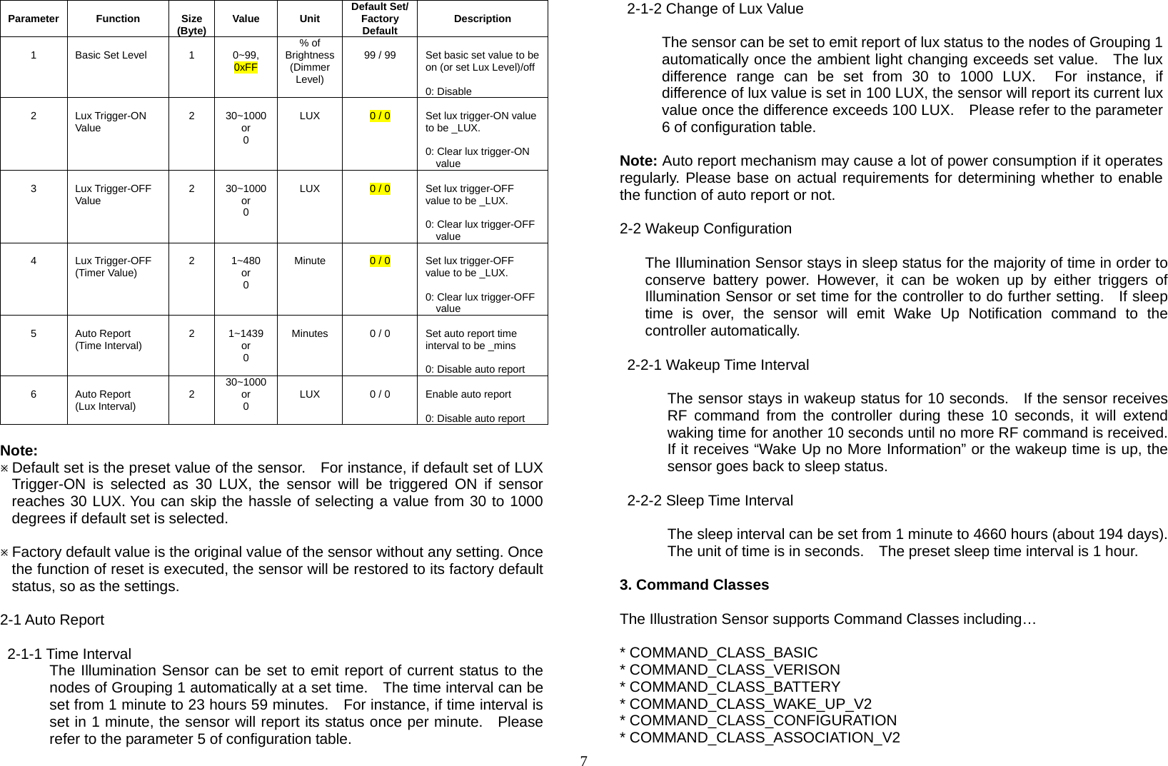
![6ALARM_REPORT and BATTERY_REPORT_COMMAND Grouping 2 includes BASIC_SET 1-1 Grouping 1 (Max. Node = 1) 1-1-1 POWER_APPLIED command Whenever power is applied, it will send ALARM_REPORT command to the nodes of Grouping 1 to inform associated devices that the sensor is powered up. ALARM_REPORT Command [Command Class Alarm, Alarm Type = 0x02, Alarm Level = 0x01] 1-1-2 MULTILEVEL_SENSOR_REPORT The sensor will emit SENSOR_MULTILEVEL_REPORT to inform the nodes of Grouping 1 automatically its current lux. Refer to the section of Z-Wave’s Configuration for settings of auto report and wakeup configuration. Illumination: SENSOR_MULTILEVEL_REPORT [Command Class Sensor Multilevel, Sensor Multilevel Report, Sensor Type = 0x03 (Luminance), Precision+Scale+Size = 0x0A, Sensor Value 1 = (High Byte of Illumination Value), Sensor Value 2 = (Low Byte of Illumination Value)] Example: Sensor Value 1 = 0x08 Sensor Value 2 = 0x02 Illumination = (Sensor Value 8*256 + Sensor Value 2) = (8*256+2) = 2050 (LUX) 1-1-3 Low Battery Report When the battery level of the sensor drops to an unacceptable level, the icon will appear on the LCD and the sensor will emit ALARM_REPORT command to the nodes of Grouping 1. ALARM_REPORT Command: [Command Class Alarm, Alarm Type = 0x01, Alarm Level = 0x01] The users can also enquire the battery status of the sensor by sending BATTERY_ GET command via controller. Once the sensor receives the command, it will return BATTERY_REPORT command. BATTERY_REPORT Command [Command Class Battery, Battery Report, Battery Level = 20%-100%] If it displays with a message of “Battery Level = 255 (0xFF)”, it implies that the sensor is at low battery status. Please replace the batteries as soon as possible, otherwise the sensor will enter Shut Down mode. Note: The sensor will emit a low battery command as long as there is a device associated into Grouping 1 of Illumination Sensor, even if the RF function is set to disable. If sensor enters Shut Down mode, the LCD display will be extinguished and no RF signal will be emitted. 1-2 Grouping 2 (Max. Node = 3) 1-2-1 BASIC_SET When the sensor is triggered, it will emit BASIC_SET_COMMAND to the nodes of Grouping 2. [Command Class Basic, Basic Set, Value = (Basic Set Level)]: send trigger-ON command [Command Class Basic, Basic Set, Value = 0(0x00)]: send trigger-OFF command Please refer to the table below, configuration parameter 1, for the setting of basic set command. 2. Z-Wave’s Configuration The table below lists the configuration parameters and the value range for users to set up the sensor.](https://usermanual.wiki/Everspring-Industry-Co/ST815/User-Guide-2106010-Page-6.png)