Everspring Industry Co ST815 Illumination Sensor with LCD User Manual Manual ST815 ZDK4 54
Everspring Industry Co Ltd Illumination Sensor with LCD Manual ST815 ZDK4 54
UserMan
1
ST815 Illumination Sensor with LCD
The Illumination Sensor with LCD (refer to as Illumination Sensor hereafter) is a
Z-WaveTM enabled device which is fully compatible with any Z-WaveTM enabled
network. Z-WaveTM enabled devices displaying the Z-WaveTM logo can also be
used with it regardless of the manufacturer, and ours can also be used in other
manufacturer’s Z-WaveTM enabled networks. Inclusion of this sensor on other
manufacturer’s Wireless Controller menu allows remote operation of connected
modules when the sensor is triggered.
The Illumination Sensor is designed to monitor the current illumination of ambient
environment. The reading of illumination can be reported to you on a regular base
at your disposal. If illumination reaches set points, the sensor will send alerts to
associated devices for further execution (such as trigger on connected lightings).
The Illumination Sensor is suitable for use in darkness and outdoor.
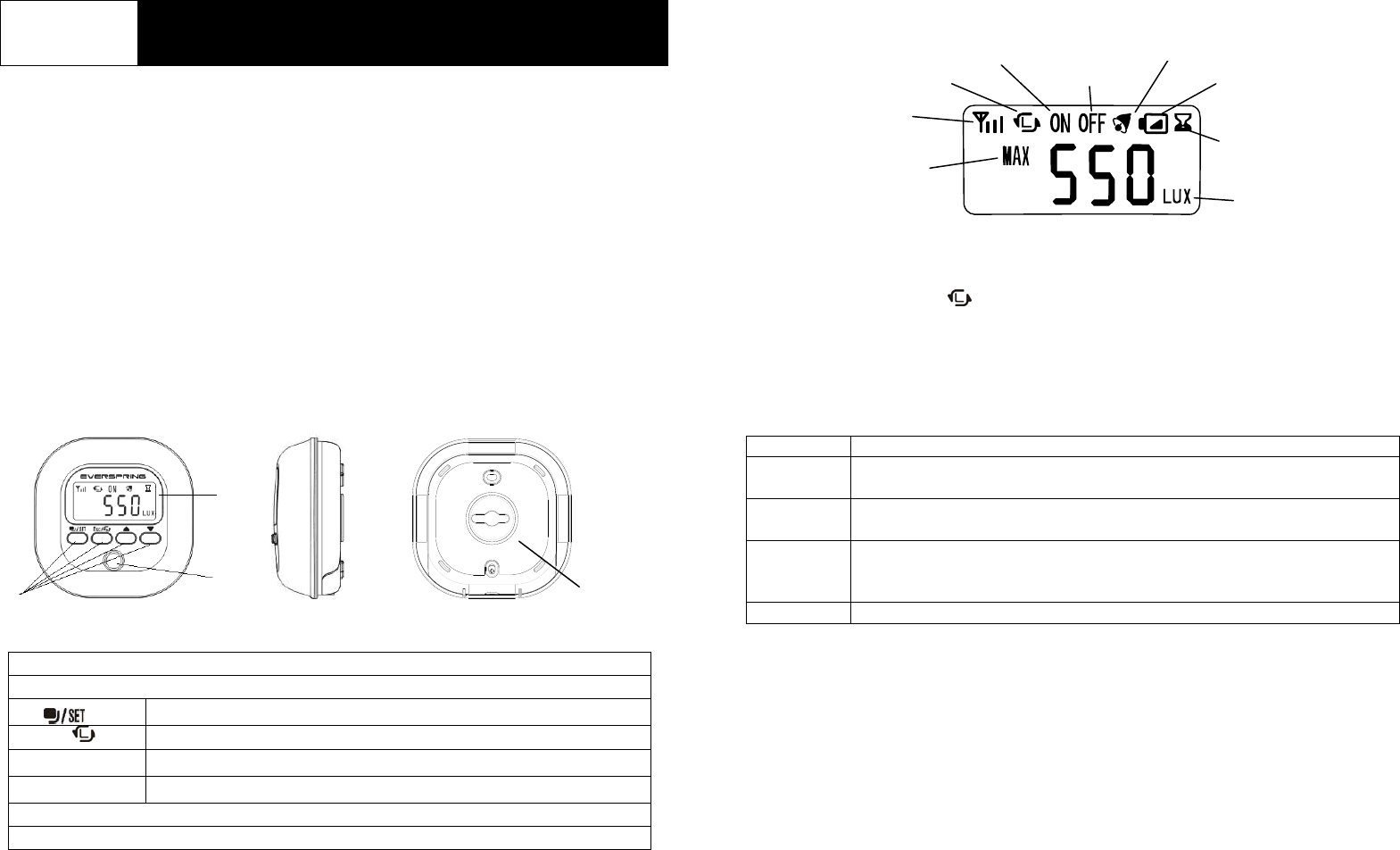
Product Overview
1 LCD Screen
2 Function Keys
Select modes/Change setting
ESC/ Cancel setting/Returning to main display/Learning
▲ Increase settings/enable RF & beep tone
▼ Decrease settings/disable RF & beep tone
3 Illumination Sensor
4 Mounting Bracket
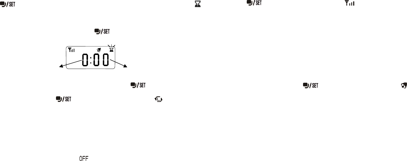
LCD Display
Include to or Exclude from Z-WaveTM Network
One of function key (ESC/ ) is used to carry out inclusion, exclusion, association
and reset. When the sensor is first powered up, the reading in RF mode is 00
which implies that it hasn’t been allocated a node ID and cannot work with Z-Wave
enabled devices. The Illumination Sensor will stay “awake” for 10 minutes when
power is first applied to allow time for configuration. Please get familiar with the
terms below before starting the operations.
Function Description
Inclusion Add a Z-Wave enabled device (e.g. Illumination Sensor) to Z-Wave
network.
Exclusion Delete a Z-Wave enabled device (e.g. Illumination Sensor) from the
network.
Association After inclusion, you have to define the relationship between devices.
Trough association, device can be assigned as master/slave, and specify
which slave is going to be controlled by which master.
Reset Restore Illumination Sensor to factory default.
The table below lists an operation summary of basic Z-Wave functions. Please
refer to the instructions for your Z-WaveTM Certificated Primary Controller to access
the setup function, and to include/exclude/associate devices. The sensor
executes the function of auto inclusion when…
Auto Inclusion
1. The power is first applied and no node ID has been allocated.
2. The execution of exclusion/reset is successful where the stored node ID is
cleared.
Side View
Front View
1
2
3
Rea
r
View
LUX Trigger ON
Linking Signal
Countdown Timer
Unit of Illumination
Radio Frequency
Status
Lux value reaches
3000 LUX
Low Battery
LUX Trigger OFF
Beep tone ON
4
2
Note: Auto inclusion timeout is 4 minutes during which the node information of
explorer frame will be emitted once every 5 seconds. Unlike “inclusion” function
as shown in the table below, the execution of auto inclusion is free from pressing
the ESC/ key.
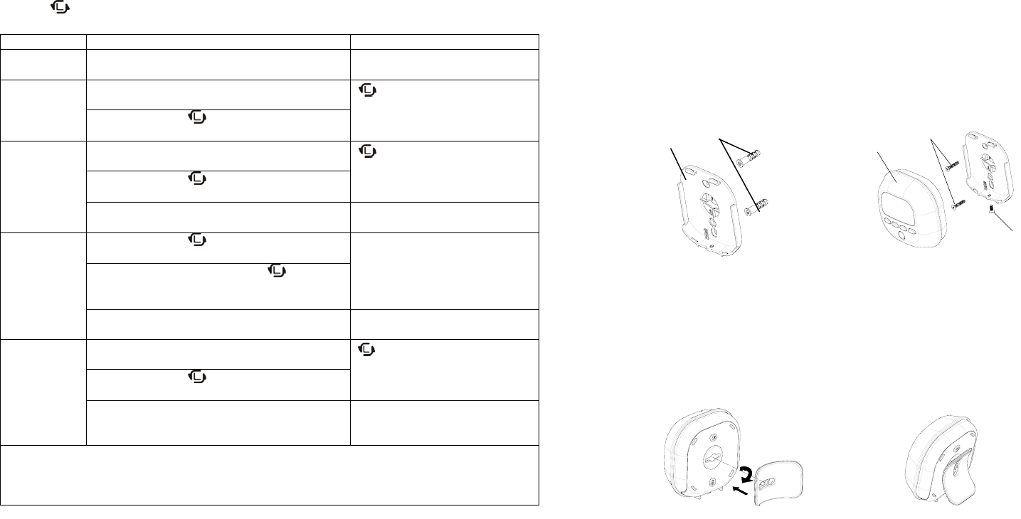
Function Description LED Indication
No node ID The Z-Wave Controller does not allocate a
node ID to the sensor. The RF reading displays 00
(MODE 5)
Inclusion 1. Have Z-Wave Controller entered
inclusion mode. flashes
2. Pressing ESC/ key 3 times within 1.5
seconds will enter inclusion mode.
Exclusion 1. Have Z-Wave Controller entered
exclusion mode. flashes
2. Pressing ESC/ key 3 times within
1.5 seconds will enter exclusion mode.
Node ID has been excluded. The RF reading displays 00
(MODE 5)
Reset 1. Pressing ESC/ key 3 times within 1.5
seconds will enter inclusion mode.
Long beep tone is sounded as
an indication of completion.
2. Within 1 second, press ESC/ key
again and hold it until long beep tone
is off.
3. Node ID has been excluded, restores to
factory default.
The RF reading displays 00
(MODE 5)
Association 1. Have Z-Wave Controller entered
association mode. flashes
2. Pressing ESC/ key 3 times within 1.5
seconds will enter association mode.
3. There are two groupings – 1 and 2.
Refer to Z-Wave’s Groupings as
described on page 5.
Including a node ID allocated by Z-Wave Controller means inclusion. Excluding a node
ID allocated by Z-Wave Controller means exclusion.
Failed or success in including/excluding the node ID can be viewed from the Z-Wave
Controller.
Choosing a Suitable Location
The Illumination Sensor can either be mounted on a wall or can be freestanding on
a table. Please consider a most suitable way before mounting/placing it.
Wall Mounting
1. Place mounting bracket over a desired location on the wall. Through 2 screw
holes of the bracket, mark the mounting surface with a pencil.
2. Where marked, drill holes into mounting surface using an appropriate size drill
bit and insert the plastic wall plugs supplied respectively.
3. Screw mounting bracket onto the mounting surface. Ensure that the screws
are flush with the bracket.
4. Snap the Illumination Sensor into place on the mounting bracket.
5. Secure with the fixing screw supplied.
FIGURE 1 FIGURE 2
Table Placing
1. Insert the stand into the hole on mounting bracket and turn 90 degrees
clockwise.
2. Once snapped in place, the sensor can be placed on a shelf, table or other
surface where the illumination measurements are desired.
FIGURE3 FIGURE 4
Note: Take care when fixing the sensor to a metal surface, or mounting within 1m of
metalwork (i.e. radiators, water pipes, etc) as this could affect the radio range of the
device.
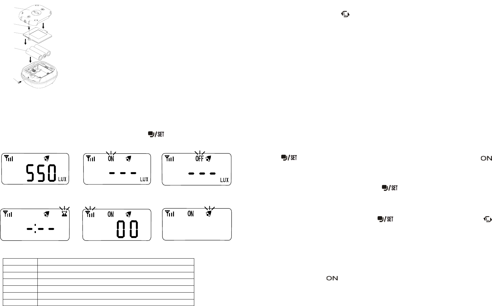
Installation
Please follow the steps below in sequence to load the batteries.
12 Plastic Wall Plug
5
4
3
3
2
3
4
1
5
1. Undo and remove the screw from the bottom edge
of the sensor to detach the rear cover.
2. Open the mounting bracket.
3. Unscrew the screw from the battery cover.
4. Remove the battery cover.
5. Insert 3 AA-size 1.5V alkaline batteries to the
battery compartment, ensuring correct polarity is
put.
6. Replace the battery cover and then engage the
sensor to the rear cover firmly.
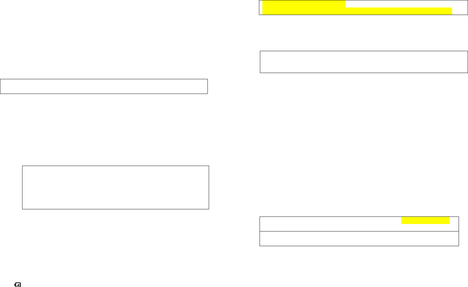
Operation
There are 6 modes available for selection. Press to select desired mode
for different settings.
Mode Function
1 Current illumination display (LUX)
2 Setting for lux trigger-ON value
3 Setting for lux trigger-OFF value
4 Countdown timer
5 Setting for turning on/off radio frequency
6 Setting for tuning on/off beep tone
MODE 1 is showing as main display on the screen. Once mode setting is finished
(MODE 2 to MODE 6), the screen will return to main display automatically after 12
seconds, or by pressing ESC/ to return to main display.
1. Illumination
1.1 Display of Current Illumination
After power-up (batteries are inserted), the LCD screen displays the current
illumination. All icons are displayed with LCD backlight illuminates 3 seconds.
Press any key will beep once and extend the backlight for another 12 seconds.
The illumination detecting range is from 0 to 3000 LUX. When illumination
reaches the limit (3000 LUX), MAX icon will be displayed on the screen.
The detecting function is disabled while you are operating the sensor. Wait for 12
seconds to enable trigger-ON or trigger-OFF function. If trigger-ON or trigger-OFF
value has already been set, detecting function will be enabled 10 seconds after
sensor is re-powered.
1.2 Lux Trigger-ON
Press and select MODE 2 to enter setting of lux trigger-ON. Icon
flashes and the screen shows the recorded trigger-ON lux. If no value is preset, the
screen will display “ - - - LUX”.
To adjust trigger-ON value, press and hold for 5 seconds until a long beep is
sounded. The “- - -” starts flashing. Use ▲ and ▼ button to adjust the lux value,
and hold ▲ or ▼ button to scan through the lux reading from 30 to 1000 (the lux
value can only be adjusted on the basis of 10 LUX per unit; the default value is 300
LUX). Once the value is selected, press to confirm setting or press ESC/
to cancel.
To clear the trigger-ON record, press both ▲ and ▼ at the same time. The
record is cleared after a long beep is sounded.
If lux of ambient light is lower than the preset trigger-ON value, Illumination Sensor
will emit RF signal to the nodes of Grouping 2. The screen of sensor will return to
MODE 1 and the icon is flashing with backlight illuminates and 4 continuous
beeps sound for 1 second. Press any key to stop the beep tone.
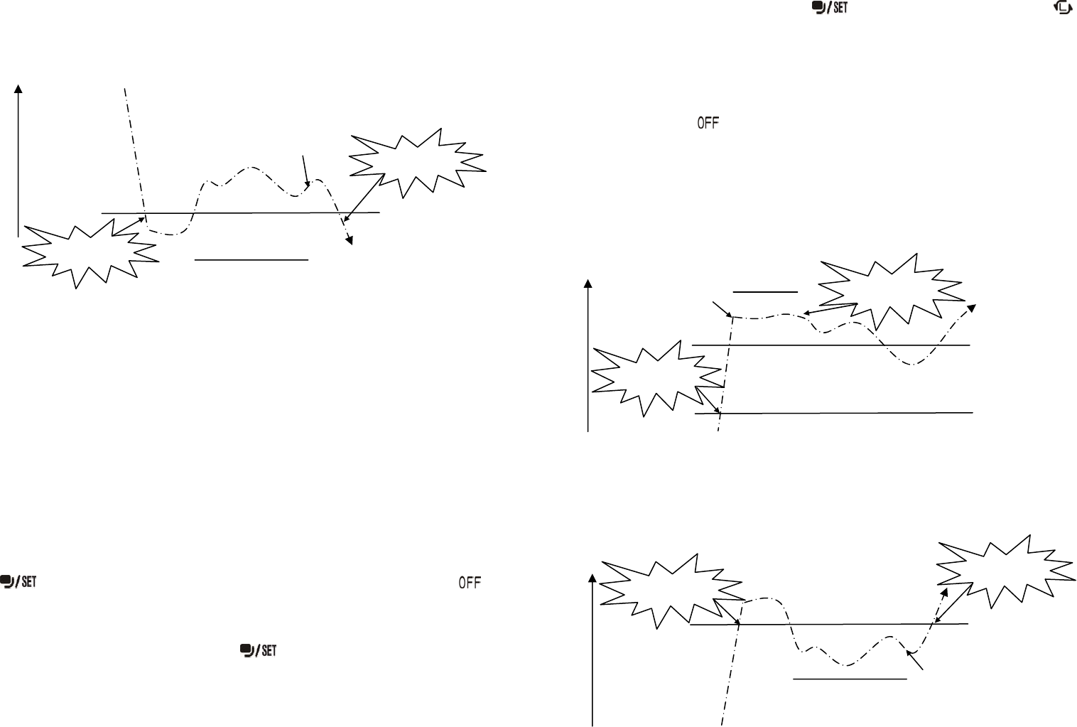
To avoid the problem of consecutive triggering, once Illumination Sensor has been
triggered, it has to be placed still for 2 minutes (restriction) before lux trigger-ON is
Mode 1
(
Main Dis
p
la
y
s
)
Mode 2 Mode 3
Mode 5 Mode 6
Mode 4
FIGURE 5
4
enabled again. To clear this restriction, the detected lux value of ambient light
during this two-minute period MUST be higher than the preset trigger-ON value,
otherwise the sensor will keep recounting 2 minutes before it can be triggered again
(FIGURE 6).
Note:
If no key has been pressed, it will return to MODE 1 automatically after 12
seconds.
While you are setting the sensor, the function of detecting trigger-ON is set to
disable to avoid false detection (because hands may obstruct the light to
Illumination Sensor during setting). The sensor must be placed still for 12
seconds for the detecting function to be enabled again. If trigger-ON value is
preset and the sensor is re-powered, it will take 10 seconds before the detecting
function is enabled.
The lux trigger-ON and trigger-OFF cannot be set equal; there MUST be at least
100 LUX differences between them. For example, if now the trigger-OFF lux is
already set to be 200 LUX, so trigger-ON lux can only be set ≦ 100 LUX or ≧
300 LUX (values between 100 LUX and 300 LUX cannot be set).
1.3 Lux Trigger-OFF
Press and select MODE 3 to enter setting of lux trigger-OFF. Icon
flashes and the screen shows the recorded trigger-OFF lux. If no value is preset,
the screen will display “ - - - LUX”.
To adjust trigger-OFF value, press and hold for 5 seconds until a long beep
is sounded. The “- - -” starts flashing. Use ▲ and ▼ button to adjust the lux value,
and hold ▲ or ▼ button to scan through the lux reading from 30 to 1000 (the lux
value can only be adjusted on the basis of 10 LUX per unit; the default value is 300
LUX). Once the value is selected, press to confirm setting or press ESC/
to cancel.
To clear the trigger-OFF record, press both ▲ and ▼ at the same time. The
record is cleared after a long beep is sounded.
If lux of ambient light is greater than preset trigger-OFF value, Illumination Sensor
will emit RF signal to the nodes of Grouping 2. The screen of sensor will return to
MODE 1 and the icon is flashing with backlight illuminates and 4 continuous
beeps sound for 1 second. Press any key to stop the beep tone.
A mechanism of 12-second placing still is designed to prevent the sensor being
triggered rapidly. Suppose the ambient light is changing rapidly, if trigger-ON value
is preset and has been triggered, and the ambient light has reached a lux level that
is higher than preset trigger-OFF value soon after, the sensor will not be triggered
until 12 seconds later. Please refer to FIGURE 7 for illustration of how the
mechanism operates.
If no trigger-ON value is preset, to avoid the problem of consecutive triggering, the
sensor has to be placed still for 2 minutes (restriction) before lux trigger-OFF is
enabled again. To clear this restriction, the detected lux value of ambient light
during this 2 minutes period MUST be lower than the preset trigger-OFF value,
otherwise the sensor will keep recounting the time before it can be triggered again
(FIGURE 8).
FIGURE 6
FIGURE 8
FIGURE 7
Preset trigger-ON
(
500 lux
)
Restriction
Clea
r
Lux trigger-ON
(triggered)
1500 lux
200 lux
Ambient
Light Lux trigger-ON
(re-triggered)
2 minutes
(
restriction
)
|
|
Ambient
Light
Restriction
Clea
r
Preset trigger-OFF
(
1000 lux
)
1500 lux
200 lux
Lux trigger-OFF
(re-triggered)
Lux trigger-OFF
(triggered)
2 minutes
(
restriction
)
|
|
Lux trigger-OFF
(triggered)
No Response 12 seconds
|
|
Ambient
Light
Lux trigger-ON
(triggered)
Preset trigger-OFF
(1000 lux)
Preset trigger-ON
(
500 lux
)
1500 lux
200 lux
5
Note:
If no key has been pressed, it will return to MODE 1 automatically after 12
seconds.
While you are setting the sensor, the function of detecting trigger-OFF is set to
disable to avoid false detection (because hands may obstruct the light to
Illumination Sensor during setting). The sensor must be placed still for 12
seconds for the detecting function to be enabled again. If trigger-OFF value is
preset and the sensor is re-powered, it will take 10 seconds before the detecting
function is enabled.
The lux trigger-ON and trigger-OFF cannot be set equal; there MUST be at least
100 LUX differences between them. For example, if now the trigger-ON lux is
already set to be 200 LUX, so trigger-ON lux can only be set ≦ 100 LUX or ≧
300 LUX (values between 100 LUX and 300 LUX cannot be set).
2. Countdown Timer
Press and select MODE 4 to enter setting of countdown time. Icon
flashes and the screen shows the recorded countdown time. If no value is preset,
the screen will display “- : - -”.
To adjust countdown time, press and hold for 5 seconds until a long beep is
sounded. The hour starts flashing.
Use ▲ and ▼ button to adjust the countdown time, and hold ▲ or ▼ button to
scan through the time from 1 hour to 8 hours. Press to set minutes, and
hold ▲ or ▼ button to scan through the time from 1 minute to 60 minutes. Once
the value is selected, press to confirm setting or press ESC/ to cancel.
To clear the last countdown time record, press both ▲ and ▼ at the same time.
The record is cleared after a long beep is sounded.
Countdown timer starts counting ONLY when the trigger-ON lux is triggered. No
response will be made if sensor is triggered ON again during countdown period.
Wait till countdown is completed before restarting the trigger-ON function.
Once countdown is completed, icon flashes on the screen with LCD backlight
on and 4 continuous beeps sound for 1 second. The sensor will emit RF signal to
the nodes in Grouping 2. The sensor has to be place still for 2 minutes before lux
trigger-ON is enabled again. To clear this restriction, the detected lux of ambient
light during this 2 minutes period MUST be higher than the preset trigger-ON value,
otherwise the sensor will keep recounting the 2 minutes before it can be triggered
again.
Note:
If no key has been pressed, it will return to MODE 1 automatically after 12
seconds.
While you are setting the sensor, the function of detecting trigger-ON is set to
disable to avoid false detection.
The countdown bias is about ±10%.
3. Radio Frequency
This function is designed to enable or disable the sending function of RF command
to the associated nodes in Grouping 2 once Illumination Sensor has been triggered
ON/OFF.
Press and select MODE 5, the icon should flash. Press ▲ to turn On
(enable) the function or ▼ to turn OFF (disable) the function.
Note:
If RF mode is OFF, no command will be sent even the Illumination Sensor has
been triggered.
If the RF reading is 00, it implies no node ID has been allocated by Z-Wave
Controller. Please execute inclusion mode as described on page 1.
4. Beep Tone
To set the beep tone, press and select MODE 6. The icon flashes. Press
▲ for ON and ▼ for OFF. If it is ON, a beep tone will be sounded whenever a
button is pressed; 4 continuous beeps will be sounded for 1 second if the sensor
has been triggered.
Programming
1. Z-Wave’s Groups (Association Command Class Version 2)
The Illumination Sensor can be set to send reports to or control associated Z-Wave
devices. It supports two association groups with one node support for Grouping 1
and three nodes support for Grouping 2.
Grouping 1 includes POWER_APPLIED, SENSOR_MULTILEVEL _REPORT,
Hour Minute
6
ALARM_REPORT and BATTERY_REPORT_COMMAND
Grouping 2 includes BASIC_SET
1-1 Grouping 1 (Max. Node = 1)
1-1-1 POWER_APPLIED command
Whenever power is applied, it will send ALARM_REPORT command to the
nodes of Grouping 1 to inform associated devices that the sensor is
powered up.
ALARM_REPORT Command
[Command Class Alarm, Alarm Type = 0x02, Alarm Level = 0x01]
1-1-2 MULTILEVEL_SENSOR_REPORT
The sensor will emit SENSOR_MULTILEVEL_REPORT to inform the nodes
of Grouping 1 automatically its current lux. Refer to the section of
Z-Wave’s Configuration for settings of auto report and wakeup
configuration.
Illumination:
SENSOR_MULTILEVEL_REPORT
[Command Class Sensor Multilevel, Sensor Multilevel
Report, Sensor Type = 0x03 (Luminance),
Precision+Scale+Size = 0x0A, Sensor Value 1 = (High Byte of
Illumination Value), Sensor Value 2 = (Low Byte of
Illumination Value)]
Example:
Sensor Value 1 = 0x08
Sensor Value 2 = 0x02
Illumination = (Sensor Value 8*256 + Sensor Value 2)
= (8*256+2) = 2050 (LUX)
1-1-3 Low Battery Report
When the battery level of the sensor drops to an unacceptable level, the
icon will appear on the LCD and the sensor will emit ALARM_REPORT
command to the nodes of Grouping 1.
ALARM_REPORT Command:
[Command Class Alarm, Alarm Type = 0x01, Alarm Level = 0x01]
The users can also enquire the battery status of the sensor by sending
BATTERY_ GET command via controller. Once the sensor receives the
command, it will return BATTERY_REPORT command.
BATTERY_REPORT Command
[Command Class Battery, Battery Report, Battery Level =
20%-100%]
If it displays with a message of “Battery Level = 255 (0xFF)”, it implies that
the sensor is at low battery status. Please replace the batteries as soon as
possible, otherwise the sensor will enter Shut Down mode.
Note:
The sensor will emit a low battery command as long as there is a device
associated into Grouping 1 of Illumination Sensor, even if the RF function
is set to disable.
If sensor enters Shut Down mode, the LCD display will be extinguished
and no RF signal will be emitted.
1-2 Grouping 2 (Max. Node = 3)
1-2-1 BASIC_SET
When the sensor is triggered, it will emit BASIC_SET_COMMAND to the
nodes of Grouping 2.
[Command Class Basic, Basic Set, Value = (Basic Set Level)]:
send trigger-ON command
[Command Class Basic, Basic Set, Value = 0(0x00)]: send
trigger-OFF command
Please refer to the table below, configuration parameter 1, for the setting of
basic set command.
2. Z-Wave’s Configuration
The table below lists the configuration parameters and the value range for users
to set up the sensor.

7
Parameter
Function
Size
(Byte)
Value
Unit Default Set/
Factory
Default
Description
1
Basic Set Level
1
0~99,
0xFF
% of
Brightness
(Dimmer
Level)
99 / 99
Set basic set value to be
on (or set Lux Level)/off
0: Disable
2
Lux Trigger-ON
Value
2
30~1000
or
0
LUX
0 / 0
Set lux trigger-ON value
to be _LUX.
0: Clear lux trigger-ON
value
3
Lux Trigger-OFF
Value
2
30~1000
or
0
LUX
0 / 0
Set lux trigger-OFF
value to be _LUX.
0: Clear lux trigger-OFF
value
4
Lux Trigger-OFF
(Timer Value)
2
1~480
or
0
Minute
0 / 0
Set lux trigger-OFF
value to be _LUX.
0: Clear lux trigger-OFF
value
5
Auto Report
(Time Interval)
2
1~1439
or
0
Minutes
0 / 0
Set auto report time
interval to be _mins
0: Disable auto report
6
Auto Report
(Lux Interval)
2 30~1000
or
0
LUX
0 / 0
Enable auto report
0: Disable auto report
Note:
Default set is the preset value of the sensor. For instance, if default set of LUX
Trigger-ON is selected as 30 LUX, the sensor will be triggered ON if sensor
reaches 30 LUX. You can skip the hassle of selecting a value from 30 to 1000
degrees if default set is selected.
Factory default value is the original value of the sensor without any setting. Once
the function of reset is executed, the sensor will be restored to its factory default
status, so as the settings.
2-1 Auto Report
2-1-1 Time Interval
The Illumination Sensor can be set to emit report of current status to the
nodes of Grouping 1 automatically at a set time. The time interval can be
set from 1 minute to 23 hours 59 minutes. For instance, if time interval is
set in 1 minute, the sensor will report its status once per minute. Please
refer to the parameter 5 of configuration table.
2-1-2 Change of Lux Value
The sensor can be set to emit report of lux status to the nodes of Grouping 1
automatically once the ambient light changing exceeds set value. The lux
difference range can be set from 30 to 1000 LUX. For instance, if
difference of lux value is set in 100 LUX, the sensor will report its current lux
value once the difference exceeds 100 LUX. Please refer to the parameter
6 of configuration table.
Note: Auto report mechanism may cause a lot of power consumption if it operates
regularly. Please base on actual requirements for determining whether to enable
the function of auto report or not.
2-2 Wakeup Configuration
The Illumination Sensor stays in sleep status for the majority of time in order to
conserve battery power. However, it can be woken up by either triggers of
Illumination Sensor or set time for the controller to do further setting. If sleep
time is over, the sensor will emit Wake Up Notification command to the
controller automatically.
2-2-1 Wakeup Time Interval
The sensor stays in wakeup status for 10 seconds. If the sensor receives
RF command from the controller during these 10 seconds, it will extend
waking time for another 10 seconds until no more RF command is received.
If it receives “Wake Up no More Information” or the wakeup time is up, the
sensor goes back to sleep status.
2-2-2 Sleep Time Interval
The sleep interval can be set from 1 minute to 4660 hours (about 194 days).
The unit of time is in seconds. The preset sleep time interval is 1 hour.
3. Command Classes
The Illustration Sensor supports Command Classes including…
* COMMAND_CLASS_BASIC
* COMMAND_CLASS_VERISON
* COMMAND_CLASS_BATTERY
* COMMAND_CLASS_WAKE_UP_V2
* COMMAND_CLASS_CONFIGURATION
* COMMAND_CLASS_ASSOCIATION_V2
8
* COMMAND_CLASS_MANUFACTURER_SPECIFIC
* COMMAND_CLASS_SENSOR_MULTILEVEL
* COMMAND_CLASS_ALARM
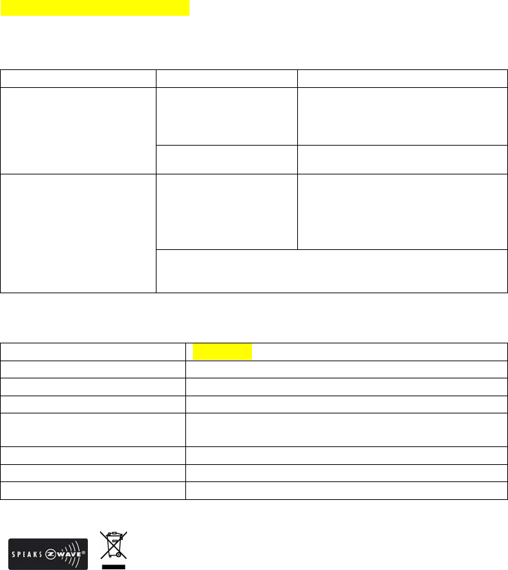
Troubleshooting
Symptom Possible Cause Recommendation
LCD cannot be displayed 1. Run out of battery
power.
2. Check if reverse
battery polarity
1. Replace a new battery
2. Refit the battery with correct
polarity
Pressing buttons are
damaged Do not open the sensor; send it to
the local retailer.
Illumination Sensor
reading is inaccurate The sensor is out of
order 1. Please leave the sensor
without operating or do any
setting for a period
2. Do not open the sensor; send
it to the local retailer.
This product does not provide exact reading; the reading of
lux value is used for your reference only for environmental
illumination setting.
Specifications
Operating Frequency 908.42 MHz
Illumination Detecting Range 0 ~ 3000 LUX
Luminance Unit LUX
Protection Degree IP44 (indoor & outdoor use)
Error Range > 1000 LUX ± 320 LUX
< 1000 LUX ± 200 LUX
Battery Type 1.5V x 3 Alkaline/AA type battery
Operating Range Up to 30 meters line of sight (indoor)
FCC ID
*Specifications are subject to change without notice
2013/09
Federal Communication Commission Interference Statement
This equipment has been tested and found to comply with the limits for a Class B
digital device, pursuant to Part 15 of the FCC Rules. These limits are designed to
provide reasonable protection against harmful interference in a residential
installation. This equipment generates, uses and can radiate radio frequency
energy and, if not installed and used in accordance with the instructions, may cause
harmful interference to radio communications. However, there is no guarantee
that interference will not occur in a particular installation. If this equipment does
cause harmful interference to radio or television reception, which can be determined
by turning the equipment off and on, the user is encouraged to try to correct the
interference by one of the following measures:
- Reorient or relocate the receiving antenna.
- Increase the separation between the equipment and receiver.
- Connect the equipment into an outlet on a circuit different from that to which the
receiver is connected.
- Consult the dealer or an experienced radio/TV technician for help.
This device complies with Part 15 of the FCC Rules. Operation is subject to the
following two conditions: (1) This device may not cause harmful interference, and (2)
this device must accept any interference received, including interference that may
cause undesired operation.
FCC Caution: Any changes or modifications not expressly approved by the party
responsible for compliance could void the user's authority to operate this
equipment.
This transmitter must not be co-located or operating in conjunction with any other
antenna or transmitter.
WARNING:
Do not dispose of electrical appliances as unsorted municipal waste, use separate
collection facilities.
Contact your local government for information regarding the collection systems
available.
If electrical appliances are disposed of in landfills or dumps, hazardous substances
can leak into the groundwater and get into the food chain, damaging your health
and well-being.
When replacing old appliances with new ones, the retailer is legally obligated to take
back your old appliance for disposal at least for free of charge.