Everspring Industry Co VC301 2.4GHz PIR Activated Lighting Camera System User Manual 711150
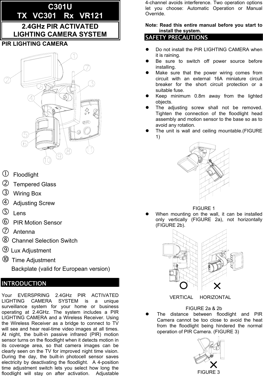
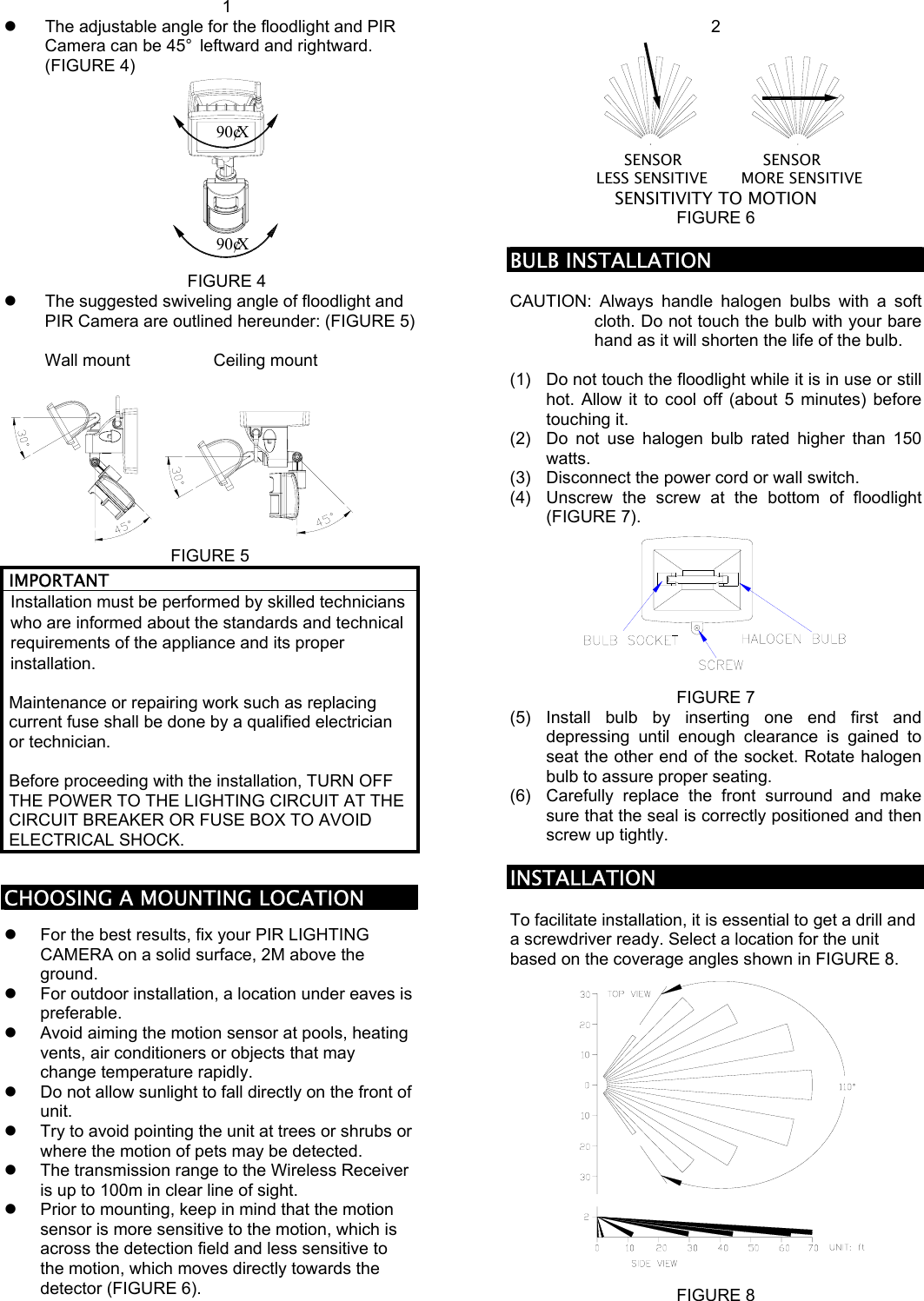
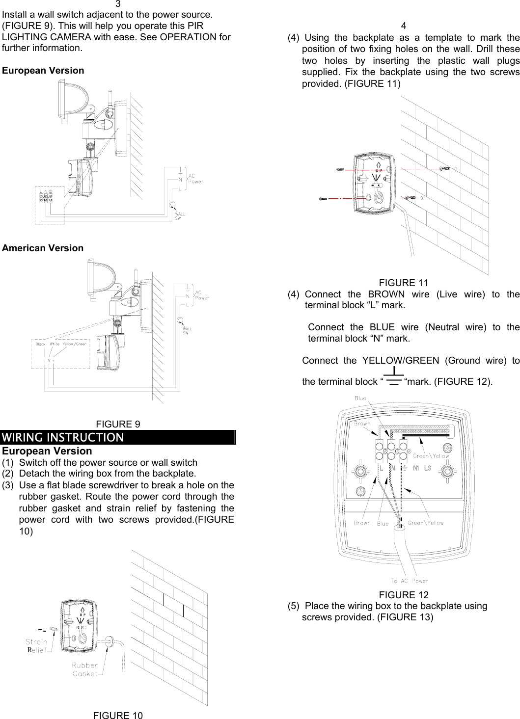
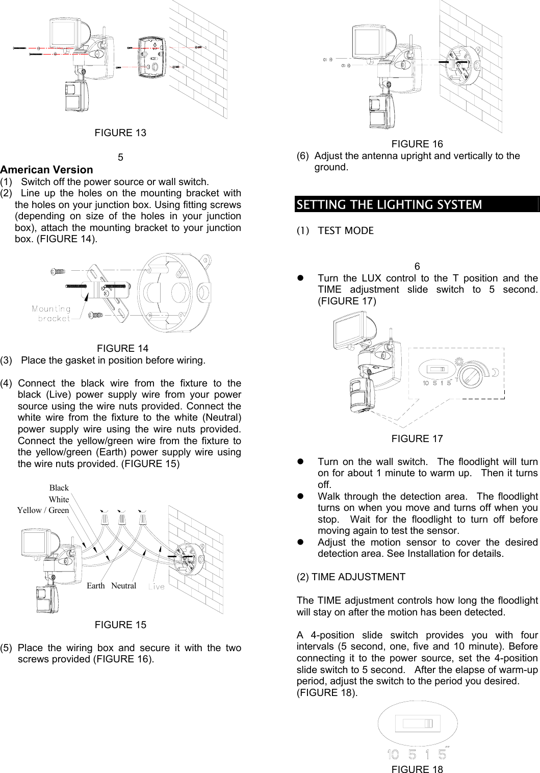
Everspring Industry Co Ltd 2.4GHz PIR Activated Lighting Camera System 711150
UserManual.wiki
>
Everspring Industry Co
>
VC301 User Manual
Users Manual
Navigation menu
Upload a User Manual
Namespaces
Wiki Guide
HTML
PDF
Info
Views
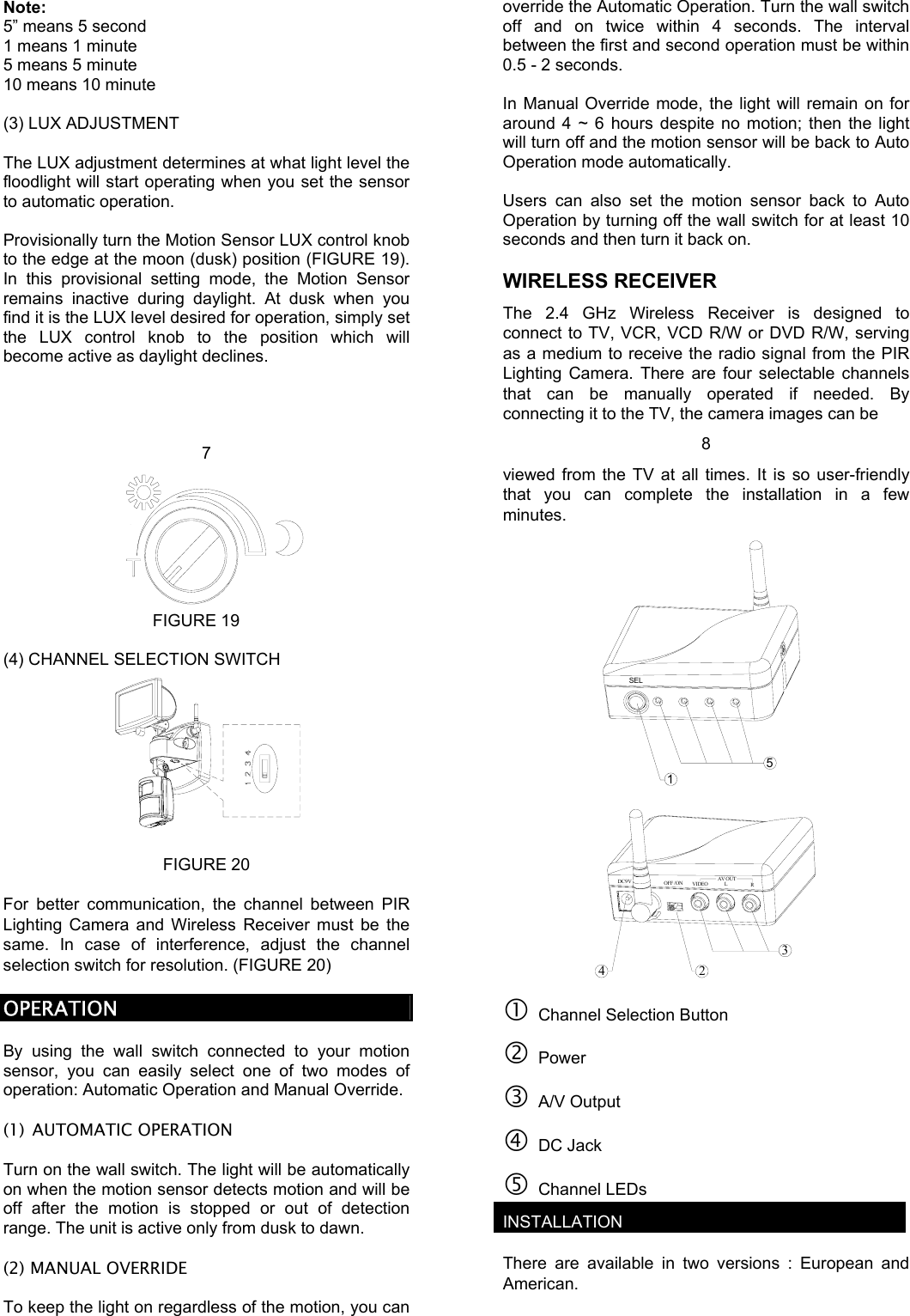
User Manual
Discussion / Help
Navigation