Everspring Industry Co VC301 2.4GHz PIR Activated Lighting Camera System User Manual 711150
Everspring Industry Co Ltd 2.4GHz PIR Activated Lighting Camera System 711150
Users Manual
C301U
TXVC301 RxVR121
2.4GHz PIR ACTIVATED
LIGHTING CAMERA SYSTEM
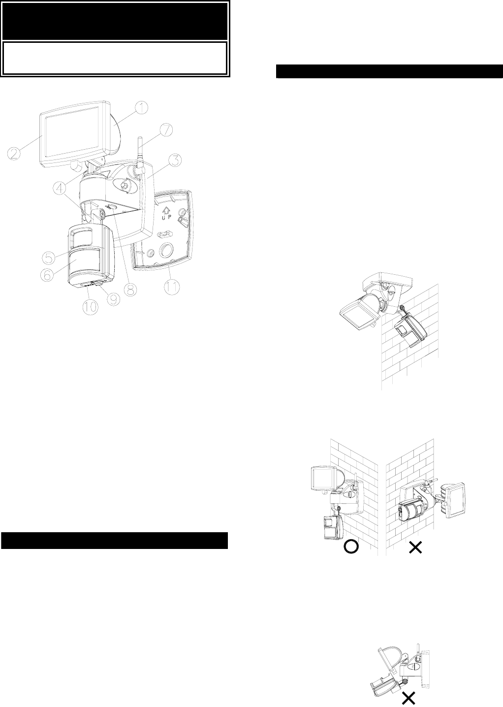
PIR LIGHTING CAMERA
c Floodlight
d Tempered Glass
e Wiring Box
f Adjusting Screw
g Lens
h PIR Motion Sensor
i Antenna
j Channel Selection Switch
k Lux Adjustment
l Time Adjustment
Backplate (valid for European version)
INTRODUCTION
Your EVERSPRING 2.4GHz PIR ACTIVATED
LIGHTING CAMERA SYSTEM is a unique
surveillance system for your home or business
operating at 2.4GHz. The system includes a PIR
LIGHTING CAMERA and a Wireless Receiver. Using
the Wireless Receiver as a bridge to connect to TV
will see and hear real-time video images at all times.
At night, the built-in passive infrared (PIR) motion
sensor turns on the floodlight when it detects motion in
its coverage area, so that camera images can be
clearly seen on the TV for improved night time vision.
During the day, the built-in photocell sensor saves
electricity by deactivating the floodlight. A 4-position
time adjustment switch lets you select how long the
floodlight will stay on after activation. Adjustable
4-channel avoids interference. Two operation options
let you choose: Automatic Operation or Manual
Override.
Note: Read this entire manual before you start to
install the system.
SAFETY PRECAUTIONS
z Do not install the PIR LIGHTING CAMERA when
it is raining.
z Be sure to switch off power source before
installing.
z Make sure that the power wiring comes from
circuit with an external 16A miniature circuit
breaker for the short circuit protection or a
suitable fuse.
z Keep minimum 0.8m away from the lighted
objects.
z The adjusting screw shall not be removed.
Tighten the connection of the floodlight head
assembly and motion sensor to the base so as to
avoid any rotation.
z The unit is wall and ceiling mountable.(FIGURE
1)
FIGURE 1
z When mounting on the wall, it can be installed
only vertically (FIGURE 2a), not horizontally
(FIGURE 2b).
VERTICAL HORIZONTAL
FIGURE 2a & 2b
z The distance between floodlight and PIR
Camera cannot be too close to avoid the heat
from the floodlight being hindered the normal
operation of PIR Camera. (FIGURE 3)
FIGURE 3
1
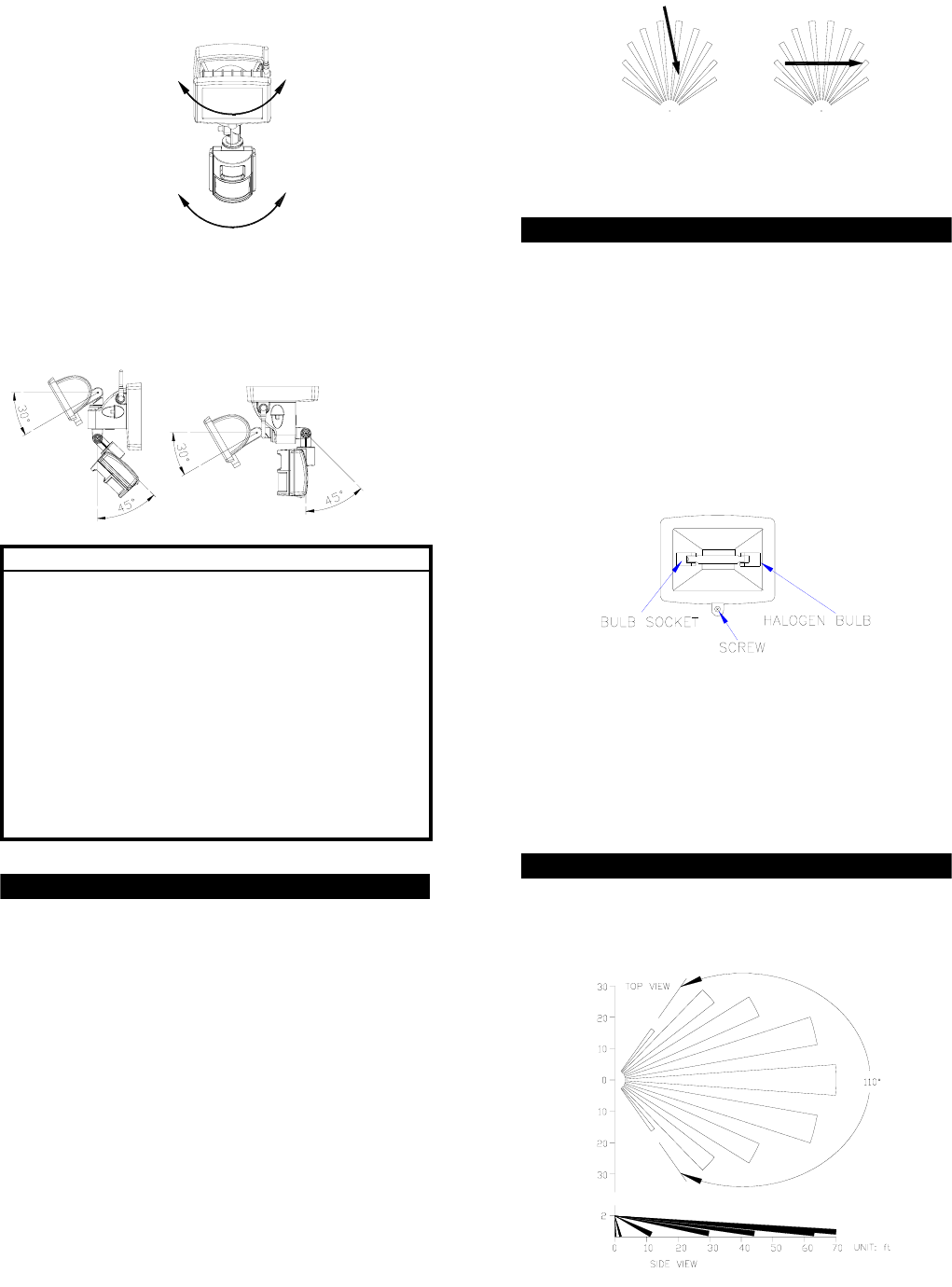
z The adjustable angle for the floodlight and PIR
Camera can be 45° leftward and rightward.
(FIGURE 4)
FIGURE 4
z The suggested swiveling angle of floodlight and
PIR Camera are outlined hereunder: (FIGURE 5)
Wall mount Ceiling mount
FIGURE 5
IMPORTANT
Installation must be performed by skilled technicians
who are informed about the standards and technical
requirements of the appliance and its proper
installation.
Maintenance or repairing work such as replacing
current fuse shall be done by a qualified electrician
or technician.
Before proceeding with the installation, TURN OFF
THE POWER TO THE LIGHTING CIRCUIT AT THE
CIRCUIT BREAKER OR FUSE BOX TO AVOID
ELECTRICAL SHOCK.
CHOOSING A MOUNTING LOCATION
z For the best results, fix your PIR LIGHTING
CAMERA on a solid surface, 2M above the
ground.
z For outdoor installation, a location under eaves is
preferable.
z Avoid aiming the motion sensor at pools, heating
vents, air conditioners or objects that may
change temperature rapidly.
z Do not allow sunlight to fall directly on the front of
unit.
z Try to avoid pointing the unit at trees or shrubs or
where the motion of pets may be detected.
z The transmission range to the Wireless Receiver
is up to 100m in clear line of sight.
z Prior to mounting, keep in mind that the motion
sensor is more sensitive to the motion, which is
across the detection field and less sensitive to
the motion, which moves directly towards the
detector (FIGURE 6).
2
SENSOR SENSOR
LESS SENSITIVE MORE SENSITIVE
SENSITIVITY TO MOTION
FIGURE 6
BULB INSTALLATION
CAUTION: Always handle halogen bulbs with a soft
cloth. Do not touch the bulb with your bare
hand as it will shorten the life of the bulb.
(1) Do not touch the floodlight while it is in use or still
hot. Allow it to cool off (about 5 minutes) before
touching it.
(2) Do not use halogen bulb rated higher than 150
watts.
(3) Disconnect the power cord or wall switch.
(4) Unscrew the screw at the bottom of floodlight
(FIGURE 7).
FIGURE 7
(5) Install bulb by inserting one end first and
depressing until enough clearance is gained to
seat the other end of the socket. Rotate halogen
bulb to assure proper seating.
(6) Carefully replace the front surround and make
sure that the seal is correctly positioned and then
screw up tightly.
INSTALLATION
To facilitate installation, it is essential to get a drill and
a screwdriver ready. Select a location for the unit
based on the coverage angles shown in FIGURE 8.
FIGURE 8
90¢X
90¢X
3
Install a wall switch adjacent to the power source.
(FIGURE 9). This will help you operate this PIR
LIGHTING CAMERA with ease. See OPERATION for
further information.
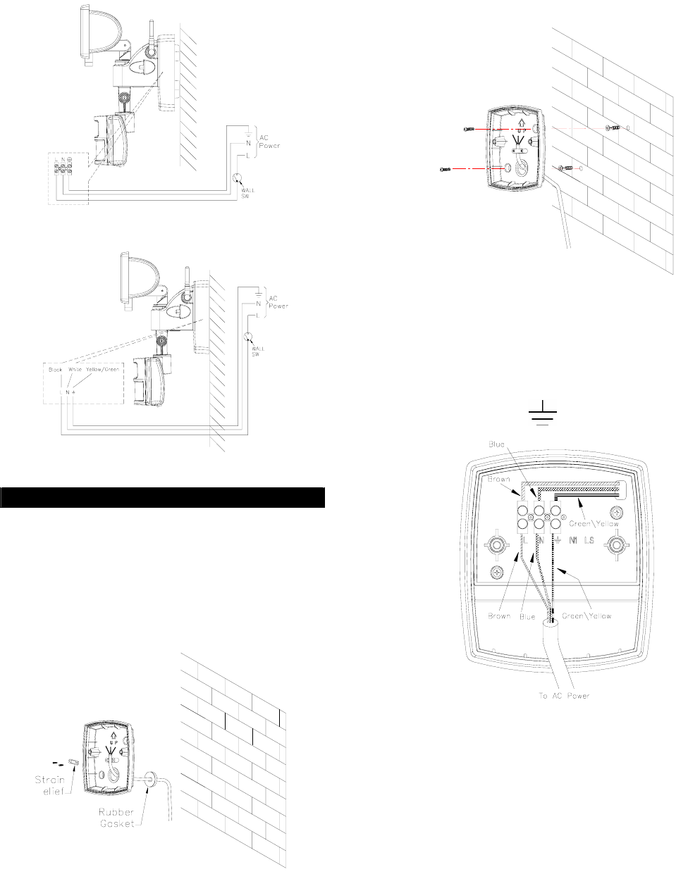
European Version
American Version
FIGURE 9
WIRING INSTRUCTION
European Version
(1) Switch off the power source or wall switch
(2) Detach the wiring box from the backplate.
(3) Use a flat blade screwdriver to break a hole on the
rubber gasket. Route the power cord through the
rubber gasket and strain relief by fastening the
power cord with two screws provided.(FIGURE
10)
R
FIGURE 10
4
(4) Using the backplate as a template to mark the
position of two fixing holes on the wall. Drill these
two holes by inserting the plastic wall plugs
supplied. Fix the backplate using the two screws
provided. (FIGURE 11)
FIGURE 11
(4) Connect the BROWN wire (Live wire) to the
terminal block “L” mark.
Connect the BLUE wire (Neutral wire) to the
terminal block “N” mark.
Connect the YELLOW/GREEN (Ground wire) to
the terminal block “ “mark. (FIGURE 12).
FIGURE 12
(5) Place the wiring box to the backplate using
screws provided. (FIGURE 13)

FIGURE 13
5
American Version
(1) Switch off the power source or wall switch.
(2) Line up the holes on the mounting bracket with
the holes on your junction box. Using fitting screws
(depending on size of the holes in your junction
box), attach the mounting bracket to your junction
box. (FIGURE 14).
FIGURE 14
(3) Place the gasket in position before wiring.
(4) Connect the black wire from the fixture to the
black (Live) power supply wire from your power
source using the wire nuts provided. Connect the
white wire from the fixture to the white (Neutral)
power supply wire using the wire nuts provided.
Connect the yellow/green wire from the fixture to
the yellow/green (Earth) power supply wire using
the wire nuts provided. (FIGURE 15)
NeutralEarth
Black
White
Yellow / Green
FIGURE 15
(5) Place the wiring box and secure it with the two
screws provided (FIGURE 16).
FIGURE 16
(6) Adjust the antenna upright and vertically to the
ground.
SETTING THE LIGHTING SYSTEM
(1) TEST MODE
6
z Turn the LUX control to the T position and the
TIME adjustment slide switch to 5 second.
(FIGURE 17)
FIGURE 17
z Turn on the wall switch. The floodlight will turn
on for about 1 minute to warm up. Then it turns
off.
z Walk through the detection area. The floodlight
turns on when you move and turns off when you
stop. Wait for the floodlight to turn off before
moving again to test the sensor.
z Adjust the motion sensor to cover the desired
detection area. See Installation for details.
(2) TIME ADJUSTMENT
The TIME adjustment controls how long the floodlight
will stay on after the motion has been detected.
A 4-position slide switch provides you with four
intervals (5 second, one, five and 10 minute). Before
connecting it to the power source, set the 4-position
slide switch to 5 second. After the elapse of warm-up
period, adjust the switch to the period you desired.
(FIGURE 18).
FIGURE 18
Note:
5” means 5 second
1 means 1 minute
5 means 5 minute
10 means 10 minute
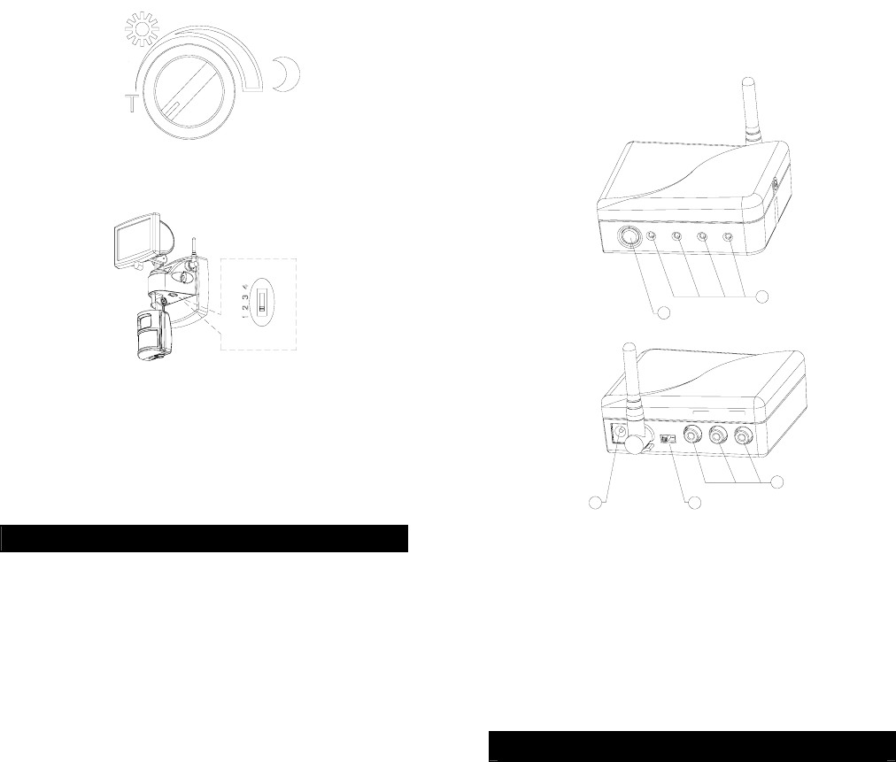
(3) LUX ADJUSTMENT
The LUX adjustment determines at what light level the
floodlight will start operating when you set the sensor
to automatic operation.
Provisionally turn the Motion Sensor LUX control knob
to the edge at the moon (dusk) position (FIGURE 19).
In this provisional setting mode, the Motion Sensor
remains inactive during daylight. At dusk when you
find it is the LUX level desired for operation, simply set
the LUX control knob to the position which will
become active as daylight declines.
7
FIGURE 19
(4) CHANNEL SELECTION SWITCH
FIGURE 20
For better communication, the channel between PIR
Lighting Camera and Wireless Receiver must be the
same. In case of interference, adjust the channel
selection switch for resolution. (FIGURE 20)
OPERATION
By using the wall switch connected to your motion
sensor, you can easily select one of two modes of
operation: Automatic Operation and Manual Override.
(1) AUTOMATIC OPERATION
Turn on the wall switch. The light will be automatically
on when the motion sensor detects motion and will be
off after the motion is stopped or out of detection
range. The unit is active only from dusk to dawn.
(2) MANUAL OVERRIDE
To keep the light on regardless of the motion, you can
override the Automatic Operation. Turn the wall switch
off and on twice within 4 seconds. The interval
between the first and second operation must be within
0.5 - 2 seconds.
In Manual Override mode, the light will remain on for
around 4 ~ 6 hours despite no motion; then the light
will turn off and the motion sensor will be back to Auto
Operation mode automatically.
Users can also set the motion sensor back to Auto
Operation by turning off the wall switch for at least 10
seconds and then turn it back on.
WIRELESS RECEIVER
The 2.4 GHz Wireless Receiver is designed to
connect to TV, VCR, VCD R/W or DVD R/W, serving
as a medium to receive the radio signal from the PIR
Lighting Camera. There are four selectable channels
that can be manually operated if needed. By
connecting it to the TV, the camera images can be
8
viewed from the TV at all times. It is so user-friendly
that you can complete the installation in a few
minutes.
5
1
SEL
4
3
2
VIDEO
DC9 V OFF /ON AV OUT
LR
c Channel Selection Button
d Power
e A/V Output
f DC Jack
g Channel LEDs
INSTALLATION
There are available in two versions : European and
American.
European Version
To connect Receiver to your TV:
1. Plug the Scart connector cable that package
included into your TV.
2. Plug the other end, yellow (video), white (audio)
and red (audio) RCA connectors into the
corresponding RCA connectors on the Receiver.
(FIGURE 21)
Power
ON/OFF
AUDIO(Red)
Antenna
DC JACK
Adapter
Scart Plug
AUDIO(White)
VIDEO(Yellow)
FIGURE 21
9
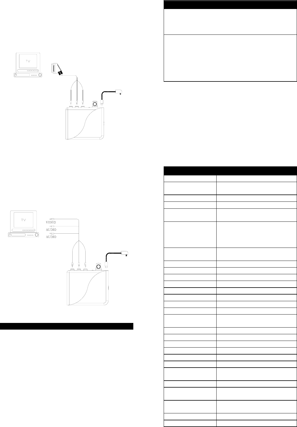
American Version
To connect Receiver to your TV:
1. Plug the yellow (video), white (audio) and red
(audio) RCA connectors into TV socket.
2. Plug the yellow (video), white (audio) and red
(audio) RCA connectors into the corresponding
RCA connectors on the Receiver. (FIGURE 22)
(Red)
(Yellow)
(White)
VIDEO(Yellow)
AUDIO(White)
AUDIO(Red)
Power
ON/OFF
Antenna
DC JACK
Adapter
FIGURE 22
OPERATION
1. Connect the Receiver with 9VDC power adapter
and set the Receiver in the same channel as that
of the video device you have planned to view.
2. Power switch: Slide the switch to On position to
turn on the power, while Off position to turn off the
power.
3. Connect the video device with power source and
turn on the TV. Then switch the TV to the video
mode. The video images can be viewed right from
the TV.
4. The Channel LED will light up when the particular
channel is in use.
TROUBLE SHOOTING
Light does not turn on:
z Confirm that you have made a correct “wiring
connection”.
z Make sure that the bulb has not burned out.
Light remains on:
z Make sure the wiring connection is correct.
z If you set the motion sensor to Manual
Override, remember that you must turn the wall
switch off for at least 10 seconds before switch
the motion sensor back to Automatic Operation.
z Check if the TIME setting is correct.
10
SPECIFICATIONS
PIR Lighting Camera Transmitter
Power Requirement AC 120 V / 60Hz
AC 230 V / 50Hz
Lighting Load Max. 150W Halogen Bulb
PIR Detection Angle Up to 110° at 20°C
PIR Detection
Distance Up to 12M at 20°C
Swiveling Angle
Lamp Part: Horizontal 90°,
Downward 30°; Upward 90°
Sensor Part: Horizontal 90°,
Downward 45°, Upward 90°
Mounting Height Recommended 2M (6.5 Ft) Wall
Mount
Wall Switch Control On / Off / Manual Override
Sensor Operation Auto
Time Adjustment 5”, 1, 5, 10
Lux Adjustment Yes
Warm Up Time About 1 min
Camera Type Color CMOS
TV System PAL/NTSC
Resolution (TV lines) 320
Pixel Array (H x V) PAL: 628 x 582
NTSC: 510 x 492
Auto Exposure Up to 1/15000 Sec.
Lens f=4.4mm F=2.0
Lens Angle 56°, Diagonal
Sensitivity <3 Lux @F1.2
S/N (Noise) >48dB
Microphone Built-in
2.4GHz Channel 2413MHz / 2432MHz
2451MHz / 2470MHz ± 200KHz
Wireless Receiver Receiver
Power Adapter Input AC 120V / 60Hz
AC 230V / 50Hz
Power Adapter
Output 9VDC 300mA
Video Output 0.9~1.35Vpp, 75Ω
Communication Max. 100m (in open space)

Range
Protection Class Class I
Protection Degree IP44
Safety UL, cUL, FCC, CE
Specifications subject to change without notice
.
A501110420R
Federal Communication Commission Interference
Statement
This equipment has been tested and found to comply with
the limits for a Class B digital device, pursuant to Part 15 of
the FCC Rules. These limits are designed to provide
reasonable protection against harmful interference in a
residential installation. This equipment generates, uses and
can radiate radio frequency energy and, if not installed and
used in accordance with the instructions, may cause harmful
interference to radio communications. However, there is no
guarantee that interference will not occur in a
11
particular installation. If this equipment does cause harmful
interference to radio or television reception, which can be
determined by turning the equipment off and on, the user is
encouraged to try to correct the interference by one of the
following measures:
- Reorient or relocate the receiving antenna.
- Increase the separation between the equipment and
receiver.
- Connect the equipment into an outlet on a circuit different
from that to which the receiver is connected.
- Consult the dealer or an experienced radio/TV technician
for help.
This device complies with Part 15 of the FCC Rules.
Operation is subject to the following two conditions: (1) This
device may not cause harmful interference, and (2) this
device must accept any interference received, including
interference that may cause undesired operation.
Per FCC 15.21, you are cautioned that changes or
modifications not expressly approved by the part responsible
for compliance could void the user’s authority to operate the
equipment.
IMPORTANT NOTE:
FCC Radiation Exposure Statement:
This equipment complies with FCC radiation exposure limits
set forth for an uncontrolled environment. End users must
follow the specific operating instructions for satisfying RF
exposure compliance.
This transmitter must not be co-located or operating in
conjunction with any other antenna or transmitter.
Do not dispose of electrical appliances as unsorted
municipal waste, use separate collection facilities.
Contact your local government for information regarding the
collection systems available.
If electrical appliances are disposed of in landfills or dumps,
hazardous substances can leak into the groundwater and get
into the food chain, damaging your health and well-being.
When replacing old appliances with new once, the retailer is
legally obligated to take back your old appliance for disposal
at least for free of charge.
12