Exalt Wireless 102P40I Digital Microwave Radio User Manual Draft Manual
Exalt Communications Inc. Digital Microwave Radio Draft Manual
UserManual.wiki
>
Exalt Wireless
>
102P40I User Manual
>
Users Manual
Contents
1.
Users Manual
2.
Professional Installation
Users Manual
Navigation menu
Upload a User Manual
Namespaces
Wiki Guide
HTML
PDF
Info
Views
User Manual
Discussion / Help
Navigation
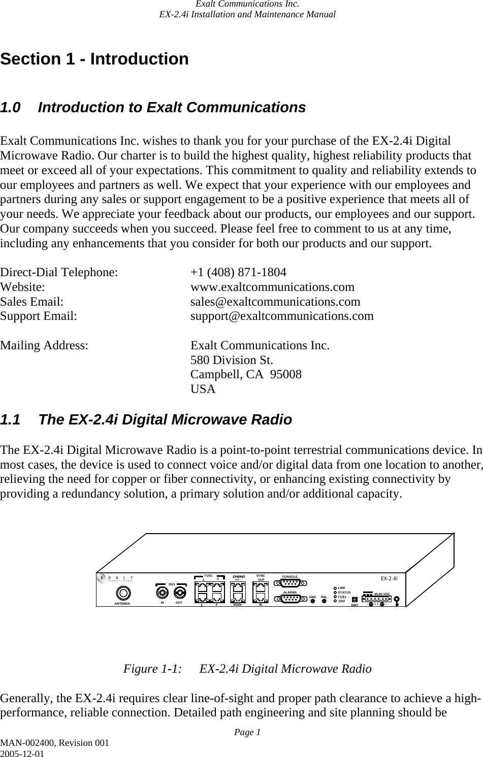
![Exalt Communications Inc. EX-2.4i Installation and Maintenance Manual Page 7 MAN-002400, Revision 001 2005-12-01 In many cases, the radio must be pre-configured for legal maximum output power before connecting to the antenna and transmission system. Instructions for adjusting the output power can be found in this section (below) and in section 5. The following information pertains to specific regulatory requirements based on up-to-date information for countries where the EX-2.4i is authorized. A list of recommended antennas can be found in section 4.3. 2.2.1 United States The EX-2.4i operates under FCC Rule Parts 15.247 as a license-exempt device, and must be professionally installed. It may only be used as a point-to-point transmission device for fixed or temporary-fixed (non-mobile) installations. The device is subject to the following restrictions: • External amplifiers may not be used to boost the power, or to overcome transmission system losses, unless the specific amplifier/cable/antenna combination has expressly been authorized by the FCC. The output power must never exceed +30dBm. • Cross-border transmissions are expressly prohibited, except with written permission from both the FCC and the governing body of the neighboring country (Cofetel for Mexico, Industry Canada for Canada) • Only parabolic dish antennas or directional flat-panel antennas may be used. No other types of antennas (omni-directional, yagi, etc.) are authorized. Parabolic dishes of either grid or solid type are allowed. Maximum gain of each type of antenna certified is: o Parabolic Dish: 30.3 dBi (6-foot diameter) o Directional Flat Panel: 20.5 dBi (~2-foot square) • Maximum transmit power with respect to FCC (USA) EIRP regulations is determined with the following equation: P = 30 - [(G - 6)/3] + L Where: P = Maximum output power of radio, in dBm G = Specified gain of antenna, in dBi, from 2400 to 2483.5 MHz L = Total transmission system losses of all elements between the radio’s RF connector and the antenna’s RF connector (all cables, connectors, lightning suppressors), in dB, as specified or measured between 2400 and 2483.5MHz The maximum EIRP allowed for this device is 52.2 dBm. The maximum RF output power is +30dBm. The professional installer is responsible to assure that RF output power has been properly adjusted so that it does not exceed the regulatory limit, per these conditions.](https://usermanual.wiki/Exalt-Wireless/102P40I.Users-Manual/User-Guide-645083-Page-17.png)

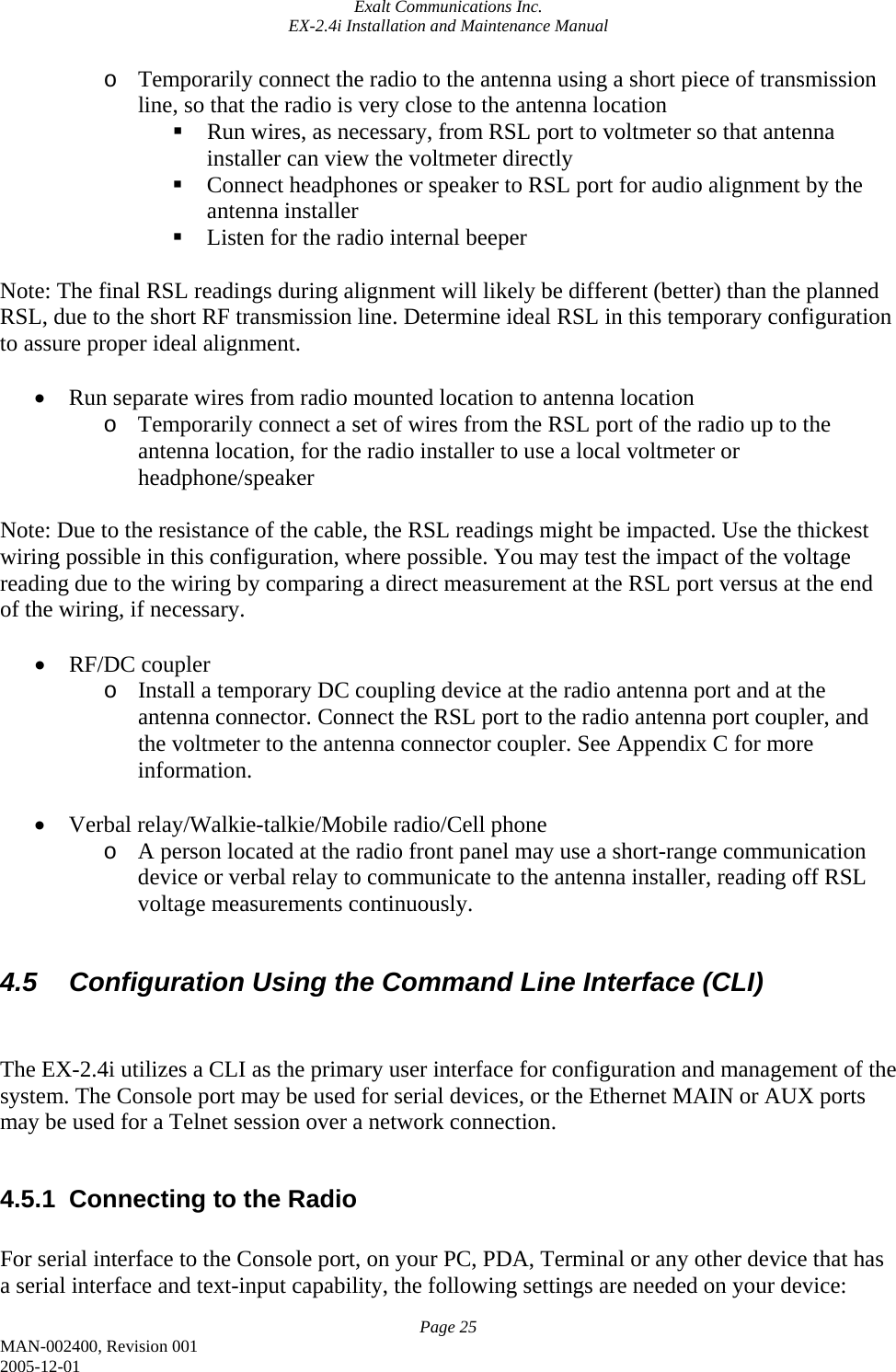
![Exalt Communications Inc. EX-2.4i Installation and Maintenance Manual Page 27 MAN-002400, Revision 001 2005-12-01 The CLI number sequence is not often used, but can be helpful for writing command scripts to pre-configure radios, or get a series of values from the device for management or monitoring. In the following paragraphs, the CLI structure is presented in a format that illustrates all of these nomenclatures simultaneously. For example, an entry such as: Set Subnet Mask, 1.2.4, [setmask xxx.xxx.xxx.xxx] Illustrates that ‘Set Subnet Mask’ would be seen in the menu tree, the number sequence for this command is 1.2.4, and direct input can be made by typing setmask followed by numeric entries for the subnet mask IP address. Such as setmask 255.255.000.000. When there is a particular choice of what to type in the CLI field, the choices are shown following the command such as: Set Main Ethernet Duplex, 1.4.1.1.2, [setmainduplex full:half:auto] Where the choices are full, half or auto, in this case. So the user would type the command, such as: setmainduplex full or 1.4.1.1.1 full In some cases, there are several entries that follow a single command. Such as with T1 interface line code. Since there are four T1 inputs, the configuration for all four are done with a single command. Such as: Set Line Code (per channel), 1.4.1.3.3.3, [setcode A:B A:B A:B A:B] (A=AIS, B=B8ZS) Where, if the user wanted AIS for channels one and two, and B8ZS for channels three and four, the user would type: setcode A A B B or 1.4.1.3.3.3 A A B B As can be seen in this last example, the choices are shown within the menu tree structure, such as A=AIS and B=B8ZS. 4.5.2.1 The root menu At the CLI root menu, you are presented with four choices: 1. Configuration/Status 2. Exit](https://usermanual.wiki/Exalt-Wireless/102P40I.Users-Manual/User-Guide-645083-Page-37.png)
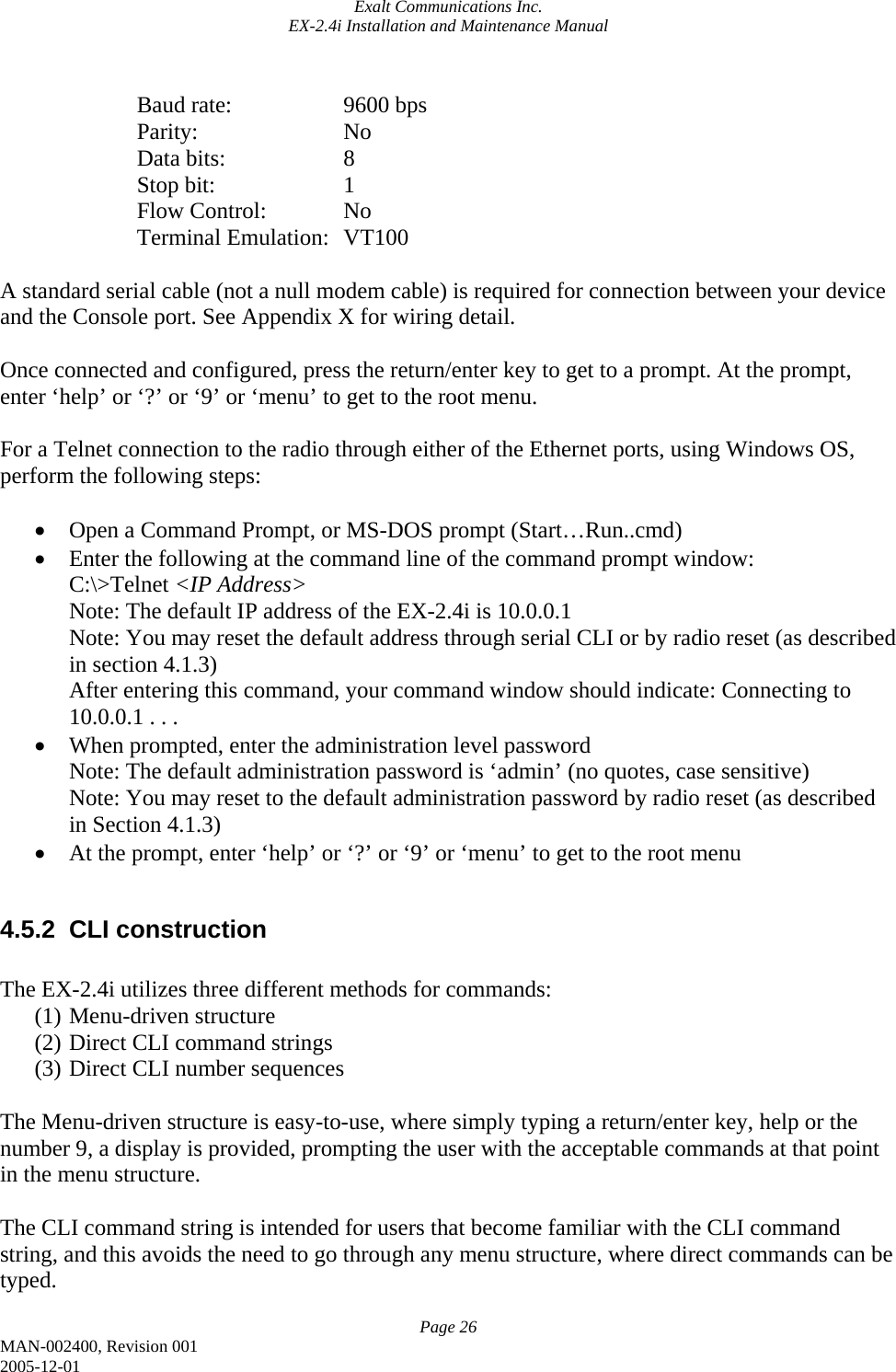
![Exalt Communications Inc. EX-2.4i Installation and Maintenance Manual Page 28 MAN-002400, Revision 001 2005-12-01 9. Help 4.5.2.2 The Configuration menu The following list is an illustration of the tree structure of the configuration menu. 1. Configuration/Status <menu> 1. Configuration wizard, 1.1, <configwiz> 2. IP setting 1.2, <IPconfig> 1. Display IP address, 1.2.1, <dispIP> 2. Set IP address, 1.2.2, [setip xxx.xxx.xxx.xxx] 3. Display Subnet Mask, 1.2.3, <dispmask> 4. Set Subnet Mask, 1.2.4, [setmask xxx.xxx.xxx.xxx] 5. Display NMS Gateway IP address, 1.2.5, <dispgate> 6. Set NMS Gateway IP address, 1.2.6, [setgate xxx.xxx.xxx.xxx] 7. Display all IP Configuration, 1.2.7, <dispIPall> 3. Configuration File Load/Save, 1.3, <configfile> 1. Load Configuration From File, 1.3.1, [configload c:\filename.cfg] 2. Save Configuration To File, 1.3.2, [configsave c:\filename.cfg] 4. Detailed Configuration Parameters, 1.4, <config> 1. Interface Configuration, 1.4.1, <configintfc> 1. Main Ethernet Configuration, 1.4.1.1, <configmain> 1. Display Main Ethernet Configuration, 1.4.1.1.1, <dispmain> 2. Set Main Ethernet Duplex, 1.4.1.1.2, [setmainduplex full:half:auto] 3. Set Main Ethernet Speed, 1.4.1.1.3, [setmainspeed 10:100] 2. Aux Ethernet Configuration, 1.4.1.2, <configaux> 1. Display Aux Ethernet Configuration, 1.4.1.2.1, <dispaux> 2. Set Aux Ethernet Duplex, 1.4.1.2.2, [setauxduplex full:half:auto] 3. Set Aux Ethernet Speed, 1.4.1.2.3, [setauxspeed 10:100] 3. T1/E1 Configuration, 1.4.1.3, <configTE> 1. Display T1/E1 Configuration, 1.4.1.3.1, <dispTE> 2. Set T1/E1 Mode, 1.4.1.3.2, [setTE T:E] 3. Configure T1, 1.4.1.3.3, <configT> 1. Set AIS (per channel), 1.4.1.3.3.1, [setAIS Y:N Y:N Y:N Y:N] (Y=AIS on, N=AIS off) 2. Set LBO (per channel), 1.4.1.3.3.2, [setTLBO 1:2:3:4:5 1:2:3:4:5 1:2:3:4:5 1:2:3:4:5] (1=0-133 ft., 2=133-266 ft., 3=266-399 ft., 4=399-533 ft., 5=533-655 ft.) 3. Set T1 Line Code (per channel), 1.4.1.3.3.3, [setTcode A:B A:B A:B A:B] (A=AIS, B=B8ZS) 4. DS3 Configuration, 1.4.1.4, <configDS3> 1. Display DS3 Configuration, 1.4.1.4.1, <dispDS3> 2. Set DS3 Mode, 1.4.1.4.2, [setDS3 On:Off] 3. Set DS3 LBO, 1.4.1.4.3, [setDS3LBO 1:2] (1=0-450 ft., 2=450-900 ft.)](https://usermanual.wiki/Exalt-Wireless/102P40I.Users-Manual/User-Guide-645083-Page-38.png)
![Exalt Communications Inc. EX-2.4i Installation and Maintenance Manual Page 29 MAN-002400, Revision 001 2005-12-01 4. Set DS3 Line Code, 1.4.1.4.4, [setDS3code A:B:H] (A=AMI, B=B3ZS, H=HDB3) 5. Display All Interface Configuration, 1.4.1.5 <dispconfigall> 2. System Configuration, 1.4.2, <configsys> 1. Transmit Power, 1.4.2.1, <pwr> 1. Display Transmit Power, 1.4.2.1.1, <disppwr> 2. Set Transmit Power, 1.4.2.1.2, [setpwr xx] (power in dBm) 2. RF frequency, 1.4.2.2, <freq> 1. Display Frequency, 1.4.2.2.1, <dispfreq> 2. Set Frequency, 1.4.2.2.2, [setfreq xxxx] (frequency in MHz) 3. RF Bandwidth, 1.4.2.3, <bw> 1. Display RF Bandwidth, 1.4.2.3.1, <dispbw> 2. Set RF Bandwidth, 1.4.2.3.2, [setbw xx] (bw in MHz) 4. Modulation, 1.4.2.4 <mod> 1. Display Modulation, 1.4.2.4.1, <dispmod> 2. Set Modulation, 1.4.2.4.2, [setmod 1:2:3] (1=QPSK, 2=16QAM, 3=64QAM) 5. External Synchronization, 1.4.2.5, <sync> 1. Display External Sync Status, 1.4.2.5.1, <dispsync> 2. Enable External Sync, 1.4.2.5.2, [setsync on:off] 6. TDD Frame Size, 1.4.2.6, <frame> 1. Display Frame Size, 1.4.2.6.1, <dispframe> 2. Set Frame Size, 1.4.2.6.2, [setframe 1:2:3:4] 7. Link Security Code, 1.4.2.7, <code> 1. Display Link Security Code, 1.4.2.7.1, <dispcode> 2. Set Link Security Code, 1.4.2.7.2, [setcode xxxxxxxx] 8. External Input Alarm, 1.4.2.8, <alarm> 1. Display External Input Alarm, 1.4.2.8.1, <dispalarm> 2. Set External Input Alarm, 1.4.2.8.2, [setalarm Y:N O:C] (Y= enable external alarm, N=disable external alarm, O=normally open, C=normally closed) 9. Display All System Configuration, 1.4.2.9, <dispconfigsysall> 3. Administration, 1.4.3, <admin> 1. System Time and Date, 1.4.3.1, <time> 1. Display Time and Date, 1.4.3.1.1, <disptime> 2. Set Time and Date, 1.4.3.1.2, [settime yyyy mm dd hh mm ss] 2. Password, 1.4.3.2, <pw> 1. Monitoring Password, 1.4.3.2.1, <monpw> 1. Display Monitor Password, 1.4.3.2.1.1, <dispmonpw> 2. Set Monitor Password, 1.4.3.2.1.2, [setmonpw xxxxxxxx] 2. Administration Password, 1.4.3.2.2, <adminpw> 1. Display Admin Password, 1.4.3.2.2.1, <dispadminpw> 2. Set Admin Password, 1.4.3.2.2.2, [setadminpw xxxxxxxx]](https://usermanual.wiki/Exalt-Wireless/102P40I.Users-Manual/User-Guide-645083-Page-39.png)
![Exalt Communications Inc. EX-2.4i Installation and Maintenance Manual Page 30 MAN-002400, Revision 001 2005-12-01 3. File Transfer, 1.4.3.3 <file> 1. Download Configuration File from Radio, 1.4.3.3.1, [downloadconfig c:\\directory\filename.cfg] 2. Upload Radio Boot Software to Radio, 1.4.3.3.2, [uploadboot c:\\directory\filename.bot] 3. Upload Radio Application Software to Radio, 1.4.3.3.3, [uploadapp c:\\directory\filename.app] 5. Upload Radio FPGA Firmware to Radio, 1.4.3.3.4, [uploadfirm c:\\directory\filname.frm] 9. Help on Configuration](https://usermanual.wiki/Exalt-Wireless/102P40I.Users-Manual/User-Guide-645083-Page-40.png)