Exalt Wireless 102P40I Digital Microwave Radio User Manual Draft Manual
Exalt Communications Inc. Digital Microwave Radio Draft Manual
Contents
- 1. Users Manual
- 2. Professional Installation
Users Manual

EX-2.4i
2.4GHz Digital Microwave Radio
Installation and Maintenance Manual
Document: MAN-002400
Revision: 001
Date: 2005-12-01
E
EX A
X A L T
L T
E
E
C o m m u n i c a t i o n s
E
EX A
X A L T
L T
E
E
C o m m u n i c a t i o n s
E
EX A
X A L T
L T
E
E
E
EX A
X A L T
L T
E
E
C o m m u n i c a t i o n s
Exalt Communications Inc.
EX-2.4i Installation and Maintenance Manual
Page i
MAN-002400, Revision 001
2005-12-01
Legal Notice
The information contained herein is the property of Exalt Communications Inc. (Exalt)
and is supplied without liability for errors or omissions. No part of this document may be
reproduced, in any form, except as authorized by contract or other written permission
from the owner.
Any brand names and product names included in this manual are trademarks, registered
trademarks, or trade names of their respective holders.
The contents of this document are current as of the date of publication. Exalt reserves the
right to change the contents without prior notice. In no event will Exalt be liable for any
special, incidental, or consequential damages or for commercial losses in connection with
the furnishing, performance, or use of this manual or equipment supplied with this
manual, including, but not limited to, the implied warranties of merchantability and
fitness for a particular purpose.
The publication of information in this document does not imply freedom from patent or
other rights of Exalt or others.
© Exalt Communications Inc., December, 2005. All rights reserved.
Y2K Statement: All imbedded or external software/firmware supplied by Exalt adhere to
the four-digit year nomenclature as required for Year 2000 compliance.
Exalt Communications Inc.
EX-2.4i Installation and Maintenance Manual
Page ii
MAN-002400, Revision 001
2005-12-01
About this Document
This manual provides a complete description of the Exalt EX-2.4i Digital Microwave
Radio and related software. The purpose of this manual is to provide the planner,
engineer, installer, system administrator, and technician with general and specific
information related to the planning, installation, operation, management and maintenance
of the device.
Revision History
Revision Date Detail
001 2005-12-01 Initial release.
Icons
Throughout this document, the following icons are used to denote specific types of information
as described here.
(Warning) Denotes information pertaining to potential danger to human life.
(Caution) Denotes information pertaining to potential danger to property.
(Note) Denotes information that may be particularly useful or unique
!
CAUTION
Exalt Communications Inc.
EX-2.4i Installation and Maintenance Manual
Page iii
MAN-002400, Revision 001
2005-12-01
General Compliance and Safety
The usage of radio transmission devices is subject to specific regulatory requirements
governed by regional legislation. In most cases, the specific device must be authorized
for use in a given country and must be installed and adjusted in accordance with specific
radio-frequency settings and in a manner that has been authorized specific to the device
itself in accordance with the specific location of the device. Some users may be
completely or partially restricted from use of the device. Please consult your
governmental agency/agencies for regulatory requirements before use, or contact Exalt or
your dealer for assistance.
This device may not be modified in any way without the express written consent of Exalt.
Modification will not only void the manufacturer warranty, but may also be expressly
illegal in accordance to government regulations. In addition, there are no user-serviceable
parts or assemblies inside the product housing. There may also be voltages, signals and
mechanisms within the device that could be harmful to human safety.
The mounting of this device and associated peripherals and connections (inclusive of
antenna mast, antenna, cabling, egress, lightning protection devices, grounding, power,
etc.) may be subject to regional requirements for health and human safety. A qualified
professional installer and an electrician are highly recommended, and may be required by
law. For example, within the USA, this device must be professionally installed.
Exalt cannot warrant the device or be found liable for any unauthorized use or installation
of the device.
Regulatory Notices
Federal Communications Commission (FCC), United States
The device is allowed to be used provided it does not cause interference to other devices.
It is not guaranteed to provide protection against interference from other electronic and
radio devices.
The system has been tested and found to comply with the limits a class B digital device,
pursuant to Part 15 of the FCC Rules. These limits are designed to provide reasonable
protection against harmful interference in a residential installation. This equipment
generates, uses and can radiate radio frequency energy and, if not installed and used in
accordance with the instructions, may cause harmful interference to radio
communications. However, there is no guarantee that interference will not occur in a
particular installation. If this equipment does cause harmful interference to radio or
television reception, which can be determined by turning the equipment off and on, the
user is encouraged to try to correct the interference by one of more of the following
measures:

Exalt Communications Inc.
EX-2.4i Installation and Maintenance Manual
Page iv
MAN-002400, Revision 001
2005-12-01
• Reorient or relocate the receiving antenna.
• Increase the separation between the equipment and receiver.
• Connect the equipment into an outlet on a circuit different from that to which the
receiver is connected.
• Consult the dealer or an experienced radio/TV technician for help.
Shielded cables and I/O cords must be used for this equipment to comply with the
relevant FCC regulations.
Changes or modifications not expressly approved in writing by Exalt may void the user’s
authority to operate this equipment.
This device must be professionally installed.
In order to comply with regulations, the output power of this device may need to be
adjusted in accordance to the associated transmission system. See section 2 of this
manual for details.
The antenna associated with this device shall be mounted in a location that is at least 10
feet away from humans that may be subject to long-term or continuous exposure.
Industry Canada (IC), Canada
This device complies with RSS-210 of Industry Canada. Operation is subject to the
following two conditions:
1. this device may not cause interference, and
2. this device must accept any interference, including interference that may cause
undesired operation of the device.
This device has been designed to operate with the antennas, as listed below, and having a
maximum gain of 30.3dBi. Antennas not included in the list or having a gain greater than
30.3dBi are strictly prohibited for use with this device. The required antenna impedance
is 50 ohms.
Manufacturer
Model #
Description Gain
(dBi)
Andrew 19T-2440-1 16-inch Solid Parabolic Dish 19
Andrew 21T-2441-1 24-inch Solid Parabolic Dish 21
Andrew 18T-2400-1 Semi-parabolic Grid 17
Andrew 26T-2400-1 Semi-parabolic Grid 23
Andrew P2F-23 2-foot Solid Parabolic Dish 21.6
Andrew P4F-23 4-foot Solid Parabolic Dish 27.3
Andrew KP3F-23 3-foot Grid Parabolic Dish 25.1
Andrew KP4F-23 4-foot Grid Parabolic Dish 27.5
Andrew KPR3F-23 2-foot Grid Parabolic Dish 23.6
Andrew KPR4F-23 4-foot Grid Parabolic Dish 27.3
Andrew QD-2402 11-inch Panel 16
Gabriel DFPS.5-23 6-inch Panel 10.3
Gabriel DFPS1-23 1-foot Panel 16.5
Gabriel P-24A36 3-foot Grid Parabolic Dish 25.7

Exalt Communications Inc.
EX-2.4i Installation and Maintenance Manual
Page v
MAN-002400, Revision 001
2005-12-01
Gabriel P-24A48 4-foot Grid Parabolic Dish 27.7
Gabriel SSP2-23 2-foot Solid Parabolic Dish 20.7
Gabriel SSP4-23 4-foot Solid Parabolic Dish 26.7
Gabriel SSP6-23 6-foot Solid Parabolic Dish 30.3
Gabriel HSSP2-23 2-foot Solid HP Parabolic Dish 20.5
Gabriel HSSP4-23 4-foot Solid HP Parabolic Dish 26.3
Gabriel HSSP6-23 6-foot Solid HP Parabolic Dish 30.0
RadioWaves SP1-2.4 1-foot Solid Parabolic Dish 14
RadioWaves SP2-2.4 2-foot Solid Parabolic Dish 21.3
RadioWaves SP3-2.4 3-foot Solid Parabolic Dish 24.3
RadioWaves SP4-2.4 4-foot Solid Parabolic Dish 27.2
RadioWaves SP6-2.4 6-foot Solid Parabolic Dish 30.3
RadioWaves G3-2.4 3-foot Grid Parabolic Dish 24.5
RadioWaves G4-2.4 4-foot Grid Parabolic Dish 27
RadioWaves G6-2.4 6-foot Grid Parabolic Dish 30.3
RFS MGAR2-23 2-foot Grid Parabolic Dish 20.8
RFS MGAR3-23 3-foot Grid Parabolic Dish 24.2
RFS MGAR4-23 4-foot Grid Parabolic Dish 27.2
RFS SPF2-23 2-foot Solid Parabolic Dish 20.5
RFS SPF3-23 3-foot Solid Parabolic Dish 24.2
RFS SPF4-23 4-foot Solid Parabolic Dish 27.1
SuperPass SPAPG20 14x15.5-inch Panel 20.5
The antenna associated with this device shall be mounted in a location that is at least 10
feet away from humans that may be subject to long-term or continuous exposure.
Safety Notices
• Review this guide in it’s entirety for important installation instructions BEFORE you
attempt to install this product.
• This product is intended to be installed, used, and maintained by experience
telecommunications personnel only.
• A properly licensed or authorized electrician should be employed to install or
evaluate/certify the installation of all power and grounding related to the use of this
equipment and all connected devices.
• The device(s) shall only be connected to AC power sources provided by the supplier or to
DC sources within the device’s specifications. A separate breaker circuit shall be
employed at the power source.
• Lightning, surge protection devices and earth grounding are required for most
installations to ensure human safety. Consult your qualified electrician.
• Servicing of this device should be performed by authorized personnel only. Do not
disassemble this device. By opening or removing any covers you may expose yourself to
hazardous energy parts. Incorrect reassembly of this product can cause a malfunction,
and/or electrical shock, when the unit is subsequently used.
• Do not connect or disconnect the power connection to the device when the power supply
is plugged into an AC outlet. To connect, first connect the power connection to the
device, then apply power (or plug in) at the outlet. To disconnect, disengage power at the
outlet or unplug, then disconnect the direct connection to the device.
• Do not insert any object of any shape or size inside this product at any time, weather
powered or not. Objects may contact hazardous energy parts that could result in a risk of
fire or personal injury.
• Liquids shall not come in contact with, or enter the inside of the device at any time.
Exalt Communications Inc.
EX-2.4i Installation and Maintenance Manual
Page vi
MAN-002400, Revision 001
2005-12-01
• Proper ventilation and/or airflow shall be provided surrounding the equipment. Do not
block any intake or exhaust vents. Items shall not come in contact with heat-sinking
materials. Assure that ambient operational and storage temperature specifications are
maintained at all times.
• Equipment is suitable for mounting on noncombustible surfaces only.
• Do not move or alter the marking labels.
Exalt Communications Inc.
EX-2.4i Installation and Maintenance Manual
Page vii
MAN-002400, Revision 001
2005-12-01
Warranty
Exalt standard hardware warranty is for two year from the date of shipment from Exalt or
their authorized Distributor. Exalt warrants that hardware will conform to the current
relevant specifications, or specifications that applied at the time of original manufacture,
and will be free from defects in material and workmanship under normal use and service.
Exalt shall within this time, at its own option, either repair or replace the defective
product within thirty (30) days of receipt of the defective product. Repaired or replaced
product will be subject to the original warranty ending date but not less than thirty (30)
days. A return material authorization (RMA) is required prior to returning equipment to
Exalt for warranty or out-of-warranty repair/evaluation.
Exalt shall not be responsible for warranty of products which have been subjected to
neglect, accident or improper use or installation.
UNLESS SPECIFICALLY EXCLUDED BY LAW, IN NO EVENT SHALL EXALT
BE LIABLE TO YOU OR ANY OTHER PARTY FOR ANY DIRECT, INDIRECT,
GENERAL, SPECIAL, INCIDENTAL, CONSEQUENTIAL, EXEMPLARY OR
OTHER DAMAGE RISING OUT OF THE USE OR INABILITY TO USE THE
PRODUCT (INCLUDING, WITHOUT LIMITATION, DAMAGES FOR LOSS OF
BUSINESS PROFITS, BUSINESS INTERRUPTION, LOSS OF BUSINESS
INFORMATION OR ANY OTHER PECUNIARY LOSS, OR FROM ANY BREACH
OF WARRANTY), EVEN IF EXALT HAS BEEN ADVISED OF THE POSSIBILITY
OF SUCH DAMAGES.
IN NO CASE SHALL EXALT’S LIABILITY EXCEED THE AMOUNT YOU PAID
FOR THE PRODUCT.
This warranty shall extend to the original equipment purchaser only, and is in lieu of all
other warranties, expressed or implied, including the implied warranties of fitness for a
particular purpose and merchantability. CUSTOMERS ARE REQUIRED TO
REGISTER THEIR PRODUCTS FOR FULL WARRANTY SUPPORT in accordance
with documentation supplied with the original delivered product(s). Unregistered
products will receive a warranty period of one (1) year. Proof-of-purchase in the form of
an invoice, payment of invoice, or delivery waybill must be supplied, if requested, to
establish original date of shipment in case of any dispute of warranty start date.
For warranty returns, cost of shipment to Exalt’s authorized service center shall be borne
by the customer. Cost of return shipment shall be borne by Exalt and will be made by
Exalt’s choice of carrier and method/schedule of shipment. Customers may expedite
return shipments, upon request, at their own expense.
Exalt Communications Inc.
EX-2.4i Installation and Maintenance Manual
Page viii
MAN-002400, Revision 001
2005-12-01
Table of Contents
Legal Notice..................................................................................................................................... i
About this Document...................................................................................................................... ii
Revision History ......................................................................................................................... ii
Icons............................................................................................................................................ ii
General Compliance and Safety.....................................................................................................iii
Regulatory Notices.........................................................................................................................iii
Safety Notices................................................................................................................................. v
Warranty ....................................................................................................................................... vii
Section 1 - Introduction .................................................................................................................. 1
1.0 Introduction to Exalt Communications........................................................................... 1
1.2 EX-2.4i Basic Features ................................................................................................... 2
Section 2 – Before Installation........................................................................................................ 5
2.0 Link Engineering and Site Planning ............................................................................... 5
2.1 Laboratory Back-to-Back Test........................................................................................ 5
2.2 RF Output Power Setting................................................................................................ 6
2.2.1 United States........................................................................................................... 7
2.2.2 Canada..................................................................................................................... 8
Section 3 - System Installation and Initiation Process.................................................................... 9
3.1 Outline of Tasks.............................................................................................................. 9
3.2 Record Keeping ..............................................................................................................9
Section 4 - Installation and Configuration.................................................................................... 11
4.0 Mechanical Configuration and Mounting..................................................................... 11
4.0.1 Rack Mounting the System................................................................................... 11
4.0.2 Wall Mounting the System ................................................................................... 12
4.0.3 Table or Rack Shelf Mounting the System........................................................... 12
4.1 User Interfaces .............................................................................................................. 12
4.1.1 Connector Overview............................................................................................. 13
4.1.2 Indicator Overview ............................................................................................... 13
4.1.3 Control Overview.................................................................................................. 15
4.2 Applying Power ............................................................................................................ 15
4.2.1 Terminating the RF Connector ............................................................................. 15
4.2.2 AC Power.............................................................................................................. 16
4.2.3 DC Power.............................................................................................................. 17
4.2.4 Backup or Emergency Power................................................................................ 18
4.3 The Antenna/Transmission System .............................................................................. 18
4.3.1 Initial Antenna Mounting...................................................................................... 20
4.3.2 Transmission Line from Antenna to Egress.......................................................... 21
4.3.3 RF Lightning Arrestor........................................................................................... 23
4.3.4 Transmission Line from Egress to Radio.............................................................. 23
4.4 Antenna Alignment....................................................................................................... 24
Exalt Communications Inc.
EX-2.4i Installation and Maintenance Manual
Page ix
MAN-002400, Revision 001
2005-12-01
4.5 Configuration Using the Command Line Interface (CLI) ............................................ 25
4.5.1 Connecting to the Radio........................................................................................ 25
4.5.2 CLI construction ................................................................................................... 26
Appendix A – Specifications ........................................................................................................ 31
A-1 Physical Specifications ................................................................................................ 31
A-2 System Specifications.................................................................................................. 31
A-3 Interfaces...................................................................................................................... 32
Appendix B - Back-to-back Testing ............................................................................................. 34
B-1 Introduction.................................................................................................................. 34
B-2 Basic Test..................................................................................................................... 34
B-3 Specification Performance Verification....................................................................... 35
Appendix C - DC Coupler for Antenna Alignment...................................................................... 38
C-1 Introduction.................................................................................................................. 38
C-2 Items Required............................................................................................................. 38
C-3 Interconnection ............................................................................................................ 38
Figures and Tables
Figure 1-1: EX-2.4i Digital Microwave Radio.......................................................................... 1
Figure 1-2: Indoor Radio Mount Interconnection...................................................................... 3
Figure 1-3: Cabinet Radio Mount Interconnection.................................................................... 3
Figure 3-1: Radio Installation Flowchart................................................................................... 9
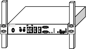
Figure 4-1: 19-inch Rack Mount ............................................................................................. 11
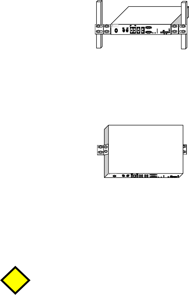
Figure 4-2: 23-inch Rack Mount ............................................................................................. 12
Figure 4-3: Wall Mount........................................................................................................... 12
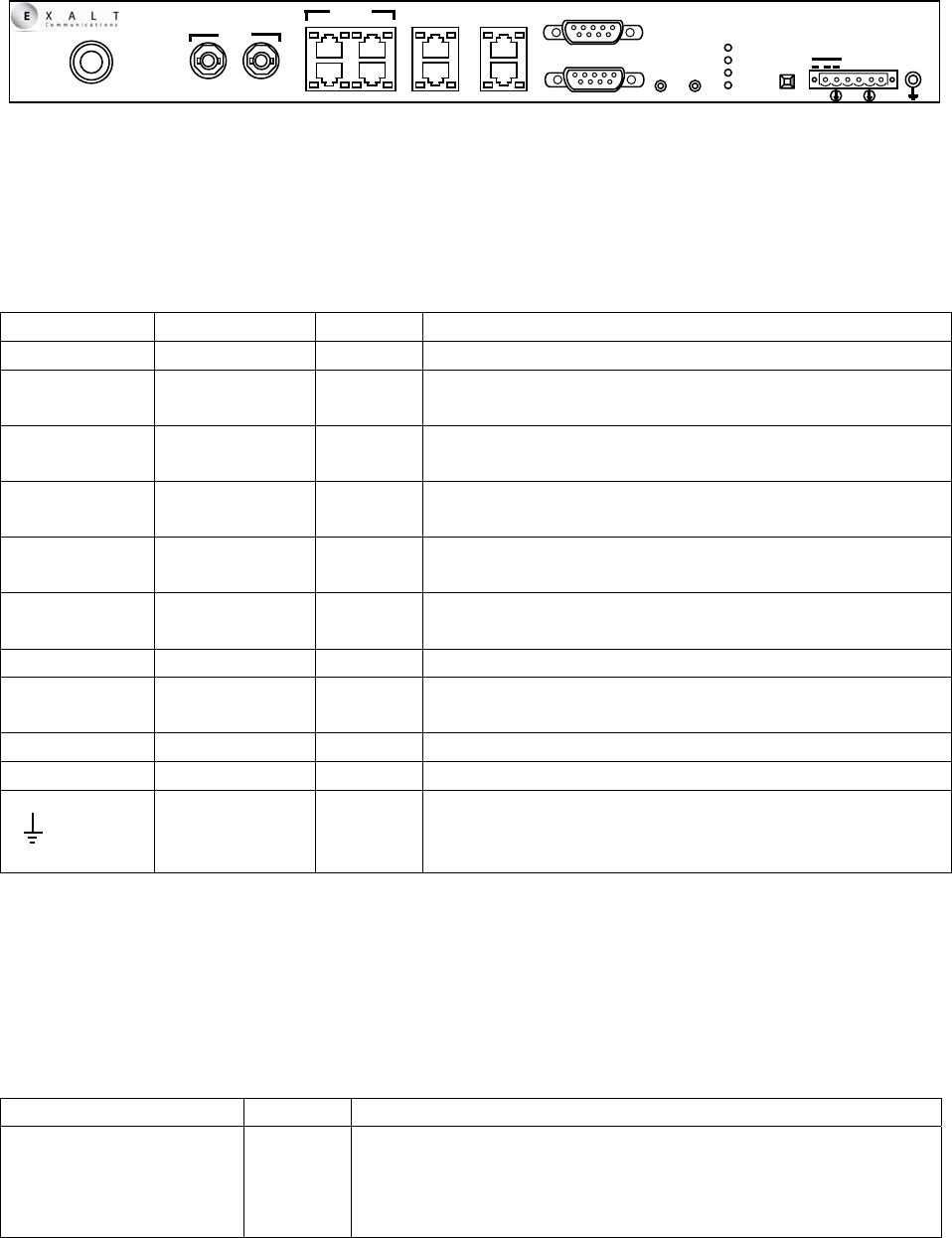
Figure 4-4: Front Panel............................................................................................................ 13
Table 4-1: Connectors ............................................................................................................ 13
Table 4-2: Indicators............................................................................................................... 15
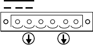
Figure 4-5: DC Connection...................................................................................................... 18
Table 4-3: Recommended Antennas ...................................................................................... 19
Figure B-1: Basic Back-to-Back Test Configuration............................................................... 35
Figure C-1: DC Coupler Interconnection................................................................................. 39
Exalt Communications Inc.
EX-2.4i Installation and Maintenance Manual
Page 1
MAN-002400, Revision 001
2005-12-01
Section 1 - Introduction
1.0 Introduction to Exalt Communications
Exalt Communications Inc. wishes to thank you for your purchase of the EX-2.4i Digital
Microwave Radio. Our charter is to build the highest quality, highest reliability products that
meet or exceed all of your expectations. This commitment to quality and reliability extends to
our employees and partners as well. We expect that your experience with our employees and
partners during any sales or support engagement to be a positive experience that meets all of
your needs. We appreciate your feedback about our products, our employees and our support.
Our company succeeds when you succeed. Please feel free to comment to us at any time,
including any enhancements that you consider for both our products and our support.
Direct-Dial Telephone: +1 (408) 871-1804
Website: www.exaltcommunications.com
Sales Email: sales@exaltcommunications.com
Support Email: support@exaltcommunications.com
Mailing Address: Exalt Communications Inc.
580 Division St.
Campbell, CA 95008
USA
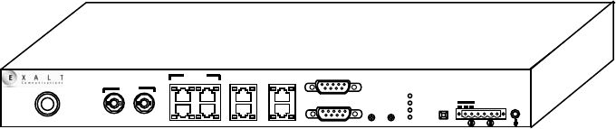
1.1 The EX-2.4i Digital Microwave Radio
The EX-2.4i Digital Microwave Radio is a point-to-point terrestrial communications device. In
most cases, the device is used to connect voice and/or digital data from one location to another,
relieving the need for copper or fiber connectivity, or enhancing existing connectivity by
providing a redundancy solution, a primary solution and/or additional capacity.
Figure 1-1: EX-2.4i Digital Microwave Radio
Generally, the EX-2.4i requires clear line-of-sight and proper path clearance to achieve a high-
performance, reliable connection. Detailed path engineering and site planning should be
EX-2.4i
ANTENNA OUT
IN
RSL
CONSOLE
A
UX
T1/E1
SYNC
MAIN IN
12
3
OUT
4
ALARMS
GND
LIN
K
STATUS
T1/E1
DS3 RMT - + + -
40-60 VDC
ETHERNET
DS3
Exalt Communications Inc.
EX-2.4i Installation and Maintenance Manual
Page 2
MAN-002400, Revision 001
2005-12-01
performed BEFORE the purchase of this equipment. This document primarily focuses on the
installation and maintenance of the device, assuming that path engineering and site planning has
already been performed. Please refer to Exalt’s document “Exalt Communications: Guidance for
Engineering and Site Planning of Terrestrial Wireless Links” for detailed information on these
activities.
The EX-2.4i utilizes radio frequencies in the range of 2400 to 2483.5MHz. In most countries this
frequency band is considered as ‘license-exempt’ or ‘unlicensed.’ This means that virtually any
user may use these frequencies freely, without paying for access, or any type of pre-notification,
post-notification or registration. As a result of this designation, users may also move or change
these systems at any time, with significant flexibility to the location, orientation and
configuration of the system. However, due also to this designation, there may be uncontrolled
interference from other similar users as well as other devices that occupy this spectrum. In these
cases, it is up to the engineering and maintenance personnel to design around existing and future
interference sources, recognizing that there is a chance that the interference conditions could be a
very dynamic condition, and outages may occur on the system as a result, and that, in some very
rare cases, the system may cause interference into another system and must be disengaged or
modified to eliminate the interference.
If the spectrum in your country is designated as ‘license-exempt’ or similar, this does not infer
that the installer may configure the system in any manner, at any location. In most cases, there
are regulations, or device-based conditions that limit the use of the device, such as maximum
gain antenna, antenna types, maximum output power, application, limited geography of use, and
other such regulations. The engineer or user is encouraged to determine these limitations and
engineer/install the system within the confines of all local regulations. This guidance is extended
to the peripheral equipment, installation and cabling of the system, which may be regulated for
human safety, electrical code, air-traffic control, and other such entities.
In certain countries, the spectrum for this product is NOT considered to be license-exempt. In
these cases, there may be additional regulatory requirements concerning the location, frequency,
power, orientation, configuration and other aspects of the system. Please consult your local
regulatory organization(s) to determine the usage requirements.
In almost all cases, either for license-exempt or other designation, the product itself must be
authorized for use in your country. Either Exalt or Exalt’s agent must have applied for
certification or authorization to allow the sale and deployment of the system within the country.
It is also possible that only certain versions or configurations of the device are allowed within a
particular country. Please contact Exalt or your dealer for information pertaining to your country.
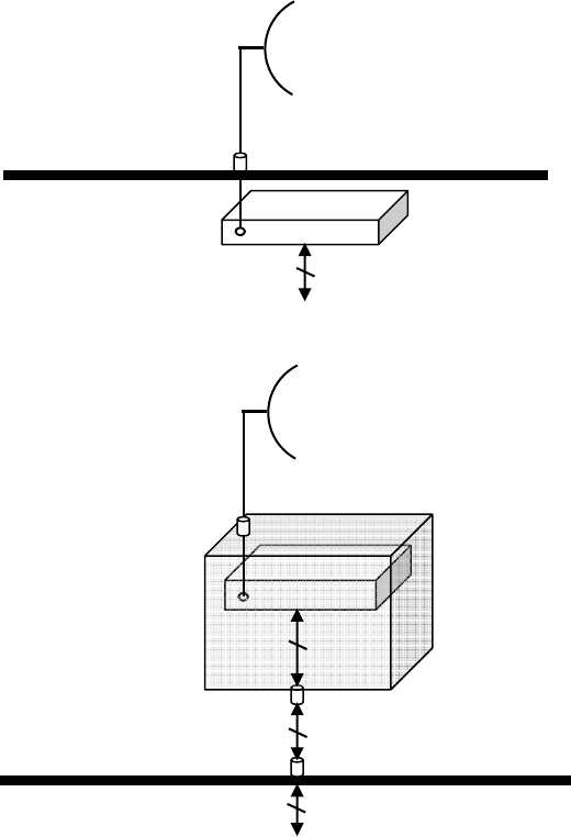
1.2 EX-2.4i Basic Features
The EX-2.4i Digital Microwave Radio is a one-piece radio device that is intended for all-indoor
or radio enclosure-based mounting. The associated antenna is typically mounted on a tower or
mast structure on a rooftop, with RF cabling running from the antenna location, with an egress
through the structure or radio enclosure, with proper lightning suppression and grounding, to the
Exalt Communications Inc.
EX-2.4i Installation and Maintenance Manual
Page 3
MAN-002400, Revision 001
2005-12-01
RF connector of the EX-2.4i. In turn, the communications interfaces and power connections are
directly applied to the EX-2.4i, or in some cases, also with an egress through the structure or
radio enclosure with proper lightning or surge suppression devices and associated grounding.
Figure 1-2: Indoor Radio Mount Interconnection
Figure 1-3: Cabinet Radio Mount Interconnection
For highest performance and reliability, it is advised to minimize the length of RF cable, and
associated transmission system losses between the antenna and the radio’s RF port.
The EX-2.4i provides connection for any of the following data communication interfaces, or a
combination thereof:
• 100BaseT Fast Ethernet, up to line-speed (100Mbps full-duplex user Ethernet data rate)
• 1-4xT1/E1 interfaces for synchronous voice traffic
• DS-3 interfaces for synchronous voice traffic
The EX-2.4i is powered by a direct DC connection (48V) or by an optional external AC adaptor
(sold separately).
RF Lightning Arrestor
Primary Transmission Line
Antenna
Secondary Transmission Line
Radio
Structure Penetration
Power/Data/Interfaces
RF Lightning Arrestor
Primary Transmission Line
Antenna
Secondary Transmission Line
Radio
Power/Data/Interfaces
Power/Data/Interfaces Lightning Arrestor(s)
Power/Data/Interfaces Lightning Arrestor(s)
Power/Data/Interfaces
Power/Data/Interfaces
Cabinet
Structure Penetration
Exalt Communications Inc.
EX-2.4i Installation and Maintenance Manual
Page 4
MAN-002400, Revision 001
2005-12-01
The EX-2.4i provides the following features and benefits:
• Computer-free link initiation for fast system initiation
• Low-latency optimization for voice and data connections
• Very high throughput and flexible interface configuration with voice+data combinations
• Encryption for extreme wireless security
• Secure and easy-to-use management and configuration
• Flexible utilized channel bandwidth selection for interference avoidance and frequency
coordination
• Agile center frequency tuning, including dynamic frequency selection for interference
avoidance and frequency coordination
• Adaptive or selectable modulation/capacity for continuous connection during adverse RF
conditions or interference
Exalt Communications Inc.
EX-2.4i Installation and Maintenance Manual
Page 5
MAN-002400, Revision 001
2005-12-01
Section 2 – Before Installation
2.0 Link Engineering and Site Planning
Any terrestrial wireless link should be designed prior to purchase and installation. Generally,
professional wireless engineering personnel are engaged to determine the viability and
requirements for a well-engineered link that will meet the user’s needs for reliability.
The reader is referred to the document “Exalt Communications: Guidance for Engineering and
Site Planning of Terrestrial Wireless Links.” This document describes all of the pre-planning and
engineering that is required to determine the following parameters:
• Antenna type/gain at each end of the link
• Antenna mounting height/location for proper path clearance
• Antenna polarization orientation
• RF Cabling type, length, connectors, route and mounting
• Antenna system grounding
• Lightning arrestor type(s), location(s) and grounding
• Radio mounting location and mechanisms
• Radio output power setting
• Radio grounding
• Anticipated Received Signal Level (RSL) at each end
With respect to radio path and site planning, the EX-2.4i is generally identical to any other
microwave terrestrial wireless system. Engineering of these systems may not require significant
specific knowledge about the EX-2.4i itself. The most important parameters being:
• RF specifications (output power, threshold, occupied bandwidth, carrier-to-interference
tolerance)
• Regulatory limitations on output power setting and antenna type/gain
2.1 Laboratory Back-to-Back Test
It is strongly advised to perform a back-to-back test, in a controlled environment, prior to
installation. This will allow you to perform several tasks which can be much more difficult to
perform once the radio link endpoints are distant from one another. Most importantly, a back-to-
back test will provide confidence that the radio link is operational and configured properly prior
to installation, so that if troubleshooting is necessary, the radio hardware and configuration
settings are eliminated from the troubleshooting process.
• Confirm that the radio system is generally operational
o Radios power-up with planned power and wiring solutions

Exalt Communications Inc.
EX-2.4i Installation and Maintenance Manual
Page 6
MAN-002400, Revision 001
2005-12-01
o RF link can connect in both directions
o Traffic can be passed across the link
• Configure connected equipment and cabling
o Test Ethernet (CAT5) cabling, and/or T1/E1/DS3 cabling, any auxiliary connector
cabling and configure all interfaces
o Configure IP settings for configuration and management
o Configure passwords and security modes
o Become familiar with the configuration and management interfaces, including the
web-based GUI interface, the SNMP interface and/or the CLI/Telnet interface.
• Configure radio parameters
o Set output power to engineered or allowed level (see section 2.2)
o Set operating center frequency and dynamic frequency setting (DFS) parameters
o Set occupied bandwidth/capacity/modulation parameters
• Make detailed radio performance measurements
o Measure output power
o Measure receiver threshold
o Confirm error-free performance
Some of the above tests may not be possible or practical within a lab environment, due to the
nature of the remote connectivity of peripheral equipment. But it is a good practice to perform as
much as possible in this environment to minimize field/installation time and troubleshooting
efforts.
Detailed performance measurements are typically not required for pre-installation, but they can
typically be easily performed at this stage and may be helpful for later troubleshooting efforts or
for internal records. During troubleshooting, there may often be a point at which a back-to-back
test should be performed to re-verify many or all of the items above, and in the case of a
suspected faulty device to help confirm the fault, and determine which end of the system is at
fault and in need of repair/replacement.
Detailed instructions for back-to-back testing are included in Appendix B.
2.2 RF Output Power Setting
The maximum RF output power is bounded by one of the following criteria (in order from
highest to lowest):
• Maximum RF output power setting of the radio device
• Maximum RF output power allowed/authorized by the local government regulations and
for this specific device
• Maximum EIRP (effective isotropic radiated power) of the transmission system
allowed/authorized by the local government regulations and for this specific device
• Desired RSL to not exceed the maximum RSL allowed by the device
• Desired RSL to minimize/eliminate interference into neighboring systems

Exalt Communications Inc.
EX-2.4i Installation and Maintenance Manual
Page 7
MAN-002400, Revision 001
2005-12-01
In many cases, the radio must be pre-configured for legal maximum output power
before connecting to the antenna and transmission system. Instructions for
adjusting the output power can be found in this section (below) and in section 5.
The following information pertains to specific regulatory requirements based on up-to-date
information for countries where the EX-2.4i is authorized. A list of recommended antennas can
be found in section 4.3.
2.2.1 United States
The EX-2.4i operates under FCC Rule Parts 15.247 as a license-exempt device, and must be
professionally installed. It may only be used as a point-to-point transmission device for fixed or
temporary-fixed (non-mobile) installations. The device is subject to the following restrictions:
• External amplifiers may not be used to boost the power, or to overcome transmission
system losses, unless the specific amplifier/cable/antenna combination has expressly been
authorized by the FCC. The output power must never exceed +30dBm.
• Cross-border transmissions are expressly prohibited, except with written permission from
both the FCC and the governing body of the neighboring country (Cofetel for Mexico,
Industry Canada for Canada)
• Only parabolic dish antennas or directional flat-panel antennas may be used. No other
types of antennas (omni-directional, yagi, etc.) are authorized. Parabolic dishes of either
grid or solid type are allowed. Maximum gain of each type of antenna certified is:
o Parabolic Dish: 30.3 dBi (6-foot diameter)
o Directional Flat Panel: 20.5 dBi (~2-foot square)
• Maximum transmit power with respect to FCC (USA) EIRP regulations is determined
with the following equation:
P = 30 - [(G - 6)/3] + L
Where:
P = Maximum output power of radio, in dBm
G = Specified gain of antenna, in dBi, from 2400 to 2483.5 MHz
L = Total transmission system losses of all elements between the radio’s RF
connector and the antenna’s RF connector (all cables, connectors, lightning
suppressors), in dB, as specified or measured between 2400 and 2483.5MHz
The maximum EIRP allowed for this device is 52.2 dBm. The maximum RF output
power is +30dBm.
The professional installer is responsible to assure that RF output power has been properly
adjusted so that it does not exceed the regulatory limit, per these conditions.
Exalt Communications Inc.
EX-2.4i Installation and Maintenance Manual
Page 8
MAN-002400, Revision 001
2005-12-01
2.2.2 Canada
The EX-2.4i operates under RSS-210 of Industry Canada regulations. Operation is subject to the
following conditions, unless express permission is granted by Industry Canada to operate in a
different manner:
• External amplifiers may not be used to boost the power, or to overcome transmission
system losses, unless the specific amplifier/cable/antenna combination has expressly been
authorized by Industry Canada.
• Cross-border transmissions are expressly prohibited, except with written permission from
both Industry Canada and the governing body of the neighboring country (FCC for USA)
• Only parabolic dish antennas or directional flat-panel antennas may be used. No other
types of antennas (omni-directional, yagi, etc.) are authorized. Parabolic dishes of either
grid or solid type are allowed. Maximum gain of each type of antenna allowed is:
o Parabolic Dish: 30.3 dBi (6-foot diameter)
o Directional Flat Panel: 20.5 dBi (~2-foot square)
A complete list of allowed antennas can be found within the Industry Canada regulatory
statement at the front section of this manual.
• Maximum transmit power (Pmax) based on Industry Canada EIRP regulations is
unlimited.
Exalt Communications Inc.
EX-2.4i Installation and Maintenance Manual
Page 9
MAN-002400, Revision 001
2005-12-01
Section 3 - System Installation and Initiation Process
This section briefly describes the process for system initiation and turn-up.
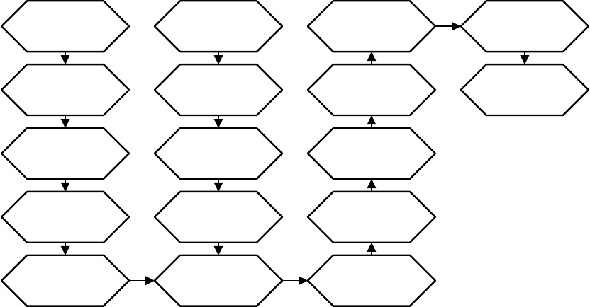
3.1 Outline of Tasks
The process of radio installation and initiation is outlined here.
Figure 3-1: Radio Installation Flowchart
3.2 Record Keeping
After installation, it is advised that the following items are recorded for the sake of ongoing
maintenance and any future troubleshooting. A record should be kept for each end of the radio
link. It is advised to store a copy of these records at the radio location, at the opposite end radio
location, and a central record-keeping storage location.
• GPS coordinates for antenna locations at each end
• Antenna heights (AGL) as mounted
• Antenna model numbers, serial numbers and specifications
• Antenna polarization as mounted
• Length/type of primary transmission line
• Model number and serial number of RF lightning arrestor used
• Length/type of secondary transmission line(s)
• Transmitter output power setting as installed
• RSL as measured after antenna alignment
Path & Site
Analysis
Link Design
Build Antenna
Structures &
Egress
Mount
Antennas &
Transmission
Line
Install & Test
Network &
Power Wiring
Read This
Manual
Completely
Perform
Back-to-Back
Test
Pre-configure
Radios
Pre-test
Network &
Power (if
possible)
Mount Radios Connect
Transmission
Line
Connect
Power
Align
Antennas to
Planned RSL
Verify LEDs
for Good Link
Test Network
Connectivity
Connect &
Test Primary
Services
Test Network
Management
System
Exalt Communications Inc.
EX-2.4i Installation and Maintenance Manual
Page 10
MAN-002400, Revision 001
2005-12-01
• Designed RSL per original design
• RSL reading with far-end power off
• Spectrum analyzer plot with far end off
• VSWR/Return Loss at Radio’s antenna connector
• Radio’s network management IP address
• Radio’s Network Management Gateway address
• Radio’s transmitter and receiver frequency
In addition, certain information may be desired for central record-keeping only:
• Security codes (should be kept in a secure place or memorized)
• Photographs of complete installation
• Customer sign-off/acceptance document (if any)
Exalt Communications Inc.
EX-2.4i Installation and Maintenance Manual
Page 11
MAN-002400, Revision 001
2005-12-01
Section 4 - Installation and Configuration
4.0 Mechanical Configuration and Mounting
The EX-2.4i is a one-piece radio design intended for deployment in a telecom equipment rack
indoors or in an appropriate environmental enclosure. The device must be deployed within an
ambient temperature range as specified and properly ventilated with no obstructions to the air
intake and exhaust. The radio occupies 1 rack unit (1.75”) in a typical telecom rack.
In most cases, additional racked equipment can be placed directly above and/or below the device
with no empty spaces in the rack. However, depending on the power consumption and
ventilation for those adjoining devices, they may pass heat to the device and render the radio
unable to cool properly, which can lead to device failure. Likewise, heat dissipation from the
radio may cause adjoining devices a similar condition. With this in mind, it is desired to have
some air space above and below the device, where possible. Where this is not possible, a thermal
analysis may be required by a professional engineer to determine the impact of thermal transfer
between all adjoining units.
It is also possible to mount the device on a wall or a table.
With respect to the connections, proper clearance shall be provided for all cables and connectors
that affix to the device. Most notably, the RF cable connector may require significant clearance
for the bend radius of the coaxial cable assembly. If desired, a properly-specified 90-degree RF
connector may be used on this connector to minimize clearance requirements, such as may be
necessary in an enclosure implementation. All RF connectors, cables and adapters must be rated
for operation over 2400 to 2483.5 MHz and their losses must be accounted for within the link
engineering design and output power settings.
4.0.1 Rack Mounting the System
Rack mounting hardware for a standard 19-inch or 23-inch rack is included in the Accessory kit.
Affix the rack mounting brackets to the sides of the unit with the screws supplied. The radio may
be flush mounted or projection mounted at a variety of depths. Rack screws are not provided, use
the appropriate screw type matching your equipment rack.
Figure 4-1: 19-inch Rack Mount
Exalt Communications Inc.
EX-2.4i Installation and Maintenance Manual
Page 12
MAN-002400, Revision 001
2005-12-01
If mounting in a 23-inch rack, the rack mount extensions must be affixed to the standard rack
brackets. Simply attach these extensions using the screws supplied.
Figure 4-2: 23-inch Rack Mount
4.0.2 Wall Mounting the System
If mounting on a wall, a wall-mount kit is required. The brackets from the wall-mount kit can be
affixed so that the mounting holes are oriented towards the bottom of the radio. It is advised that
the brackets be mounted in the most central mounting location to the chassis, as shown.
Figure 4-3: Wall Mount
4.0.3 Table or Rack Shelf Mounting the System
If mounting on a table or a rack shelf, it is advised to affix the rubber feet that are included in the
accessory kit. Simply remove the adhesive cover from the rubber feet, and affix the feet to the
bottom of the unit near the corners. These feet will help keep the radio stable on a wooden or
metal surface to keep it from sliding.
In many areas, it is necessary to strap the equipment to a table or rack shelf if
mounting in this manner. In case of earthquake or other shock or vibration, or an
accidental pull of a cable, the unit should be secured from falling.
4.1 User Interfaces
This section is intended to provide a brief familiarization of the connectors, controls and
indicators on the device. More details about each item are found in other sections of this
document.
CAUTION
Exalt Communications Inc.
EX-2.4i Installation and Maintenance Manual
Page 13
MAN-002400, Revision 001
2005-12-01
The EX-2.4i front panel is shown here:
Figure 4-4: Front Panel
4.1.1 Connector Overview
The following table provides detail of the connectors on the front panel of the EX-2.4i.
Label Type Gender Function
Antenna N F Transmission line connection to antenna
DS3
(In/Out) BNC F Primary ports for User DS3 circuits to traverse link
T1/E1
(1-4) RJ-48C F Primary ports for User T1 or E1 circuits to traverse
link
Ethernet
(Main/Aux) CAT5 F Primary ports for user Ethernet and/or management
data (10BaseT or 100BaseT) to traverse link
Sync
(In/Out) CAT5 F External radio synchronizing source (e.g. GPS) input
and output
Console 9-pin sub-D F Management port (serial) for PC/PDA for Command
Line Interface (CLI) communications
Alarms 9-pin sub-D F External alarm inputs and outputs
GND
(Ground) Bantam F Common (return) voltmeter port for measuring
received signal level
RSL Bantam F Voltmeter port for measuring received signal level
40-60VDC 6-pin Modular M DC power input from DC source or AC adaptor
(Ground)
Threaded
(M5)
Receptacle
F Chassis ground connection (M5 x 0.8 thread)
Table 4-1: Connectors
4.1.2 Indicator Overview
The following table provides detail of the indicators on the EX-2.4i.
Location/Label Type Function
Link 3-color
LED Indicates RF link status:
Green Solid = Error-free connection (BER<10e-6)
Yellow Solid = Errored connection (10e-3>BER >10e-6)
Red Solid = No link (BER>10e-3)
EX-2.4i
ANTENNA
DS3
OUT
IN RSL
CONSOLE
ETHERNET
AUX
T1/E1 SYNC
MAIN IN
1 2
3
OUT
4
ALARMS
GND
LINK
STATUS
T1/E1
DS3 RMT - ++ -
40-60 VDC

Exalt Communications Inc.
EX-2.4i Installation and Maintenance Manual
Page 14
MAN-002400, Revision 001
2005-12-01
Red Blink = No remote information available
Off = System is not properly powered/system failure
Status 3-color
LED Indicates system status:
Green Solid = No alarm conditions (normal operation)
Yellow Solid = Alarm conditions, not traffic effecting
Yellow Blink Slow = In loopback (from this end)
Yellow Blink Fast = In loopback (at this end)
Red Solid = Alarm conditions, traffic effecting
Red Blink = No remote information available
Off = System is not properly powered/system failure
T1/E1 3-color
LED Indicates T1/E1 support:
Green Solid = T1/E1 interfaces supported
Yellow Solid = T1/E1 interfaces supported, but disabled
Off = T1/E1 support not alarmed; System is not properly
powered/system failure
DS3 3-color
LED Indicates DS3 support:
Green Solid = DS3 interface is supported
Yellow Solid = DS3 interface supported, but disabled
Off = DS3 support not alarmed; System is not properly
powered/system failure
Left Corner Data Green
LED Solid = Negotiated @ 100Mbps
Blink = Negotiated @ 10Mbps
Off = No connection negotiated
Right Corner Data Green
LED Solid/Blinking = Data is present
Off = No data present
Left Corner T1/E1 Green
LED Solid = Connection present (clocking confirmed)
Blink Fast = Connection present, coding/clock problem
Blink Slow = Connection present but unexpected
Off = No connection/clock
Right Corner T1/E1 Yellow
LED Solid = Loopback
Blink Fast = AIS
Off = No loopback, No AIS
Remote End Button Amber
LED Off = Remote end Link & Status LEDs are both green
Solid = There is no remote end status available
Blink = There are alarm conditions (Link and/or Status
LEDs are non-green) at the remote end
Sync In Left Corner Green
LED On = Sync input connected
Off = Sync input not connected
Sync In Right Corner Green
LED Unused
Sync Out Left Corner Green
LED On = Sync output connected
Off = Sync output not connected
Sync Out Right Corner Green
LED Unused
Summary (Rear Panel) 3-color
LED Indicates overall status (from the rear panel):
Green = Link and Status are both green

Exalt Communications Inc.
EX-2.4i Installation and Maintenance Manual
Page 15
MAN-002400, Revision 001
2005-12-01
Yellow = Link and/or Status are in a yellow state
Red = Link and/or Status are in a red state
Off = System is not properly powered/system failure
Table 4-2: Indicators
4.1.3 Control Overview
There is only one external control on the EX-2.4i, a button labeled “RMT” (Remote). This button
allows the user to easily and quickly evaluate the status of the remote end radio. Press and hold
the button and, while held, all local end status LEDs (Link, Status, T1/E1, DS3) represent the
status of the LEDs on the remote end radio. In addition, the RSL Voltage also represents the
voltage that is present at the remote end.
When the amber LED that is embedded in the RMT is flashing, this is an alert that the remote
end has an alarm condition, and the button should be pressed to determine the alarm conditions.
When the RMT button is pressed and held, and all local LEDs flash, there is no far end
information available. This indicates that the remote radio is either not powered, is booting, or is
not linked in the direction towards the local radio, or the local radio is receiving excessive errors
in this direction. It could also indicate a serious failure of the local or remote radio. Examining
local end LEDs (when this button is not pressed) in combination with the remote end information
(from a technician located at the far end, and/or when the button is pressed) can aid in
troubleshooting analysis.
4.2 Applying Power
The radio requires a DC power source within specifications, as stated. The DC may be provided
from a DC battery source, central lab/rack supply or from Exalt’s AC adaptor (sold separately).
4.2.1 Terminating the RF Connector
Before applying power, the device’s RF connector must be properly terminated into a 50-ohm
load. If this is not performed, the radio may be damaged by simply applying power. Also, there
are human safety factors to consider regarding potentially harmful RF radiation.
There are a few simple means to accommodate this proper termination:
• Connect a 50-ohm coaxial termination device to the RF port of the radio. The termination
needs to be rated to 1W (or more). Example(s) include:
o Broadwave Technologies P/N 552-200-002, or similar
• Connect the complete transmission system. That is, the RF cabling including the antenna.
The cabled antenna provides a proper termination for the RF output.
Exalt Communications Inc.
EX-2.4i Installation and Maintenance Manual
Page 16
MAN-002400, Revision 001
2005-12-01
• Connect a fixed (or a series of fixed) 50-ohm attenuator(s) to the RF connector, either
directly or at the end of an RF transmission line. The attenuator should be at least 20dB
as specified at 2400 MHz, and rated for a minimum of 1W input power.
o Broadwave Technologies P/N 352-103-xxx
o Bird 2-A-MFN-xx
o JFW Industries 50FP-xxx-H6-N
4.2.2 AC Power
The optional AC adaptor (sold separately) comes equipped for easy direct connection to the
device. The AC rating of the adaptor accepts most worldwide standard voltages and frequencies.
Please refer to the input voltage requirements stated on the label that is affixed to the adaptor to
assure that the adaptor may be used with your AC mains supply. The AC plug outlet provided
with the adaptor may need to be replaced to match your country configuration. The adaptor cable
uses a standard connector for this cable so that you can simply use a pre-wired cable that is
appropriate to your outlet configuration. If that type of cable is not available, the existing AC
plug end can be severed and a replacement plug affixed. Consult a qualified electrician for this
activity.
Do not plug the adaptor into your mains power. First, verify that the RF connector is properly
terminated (per section 4.2.1 above) and then plug in the radio-side connector from the AC
adaptor to the radio. If your AC mains can be turned off by a switch, disable the power first, plug
the AC side of the adaptor into the AC mains socket, and then enable power to the circuit. If your
AC mains cannot be turned off, simply plug into the AC main socket to apply power. Verify
radio is active by observing LED activity. All LEDs will flash at initial power cycle, for the user
to verify that all LEDs are operational.
It is strongly encouraged that the AC Mains supply be fused or on a breaker to ensure against
over-voltage and/or over-current situations to provide some form of protection to the radio
electronics and other devices that may be connected to the same supply. In addition, if your AC
power is subject to significant spikes or variation, power conditioning is a worthwhile
investment, as the quality of mains power may have a direct impact on the device operation,
performance and/or reliability. Many users will deploy an Uninterruptible Power Source (UPS)
or other form of battery-backed system, to protect against brown-out and black-out conditions, as
well as to condition the power being presented to the adaptor.
It is also important to evaluate the opportunity for lightning or other similar surges to become
present on the powering system, including the ability for surges to couple to the power wiring
system. If an evaluation indicates that there is a potential likelihood for these conditions to occur,
additional surge protection may be recommended for the input power wiring, especially between
the adaptor and the radio’s DC input connector, to protect the radio electronics.
The above statement is similarly true for every wired connection to the device. While the
configuration for surge suppression or line conditioning is of a different type for each kind of
signal interface, the opportunity for damage to the device, loss of communications and property

Exalt Communications Inc.
EX-2.4i Installation and Maintenance Manual
Page 17
MAN-002400, Revision 001
2005-12-01
can be significant. In some cases, there can also be a risk to human life by not protecting against
lightning entering a building through wiring or improper grounding. If you do not have
experience in this type of installation practice, it is strongly suggested that a qualified electrician
and/or telecoms professional is consulted during the installation of the equipment and wiring.
4.2.3 DC Power
The device accepts direct DC power within the voltage specifications stated (48 Volts, nominal)
and with enough current delivery capacity, also per the specifications stated. The DC power may
be connected as a positive or negative voltage supply, and may be referenced to ground or may
be ‘floating’ (differential voltage). There are different system grounding considerations
depending on the nature of the DC supply grounding, and your qualified electrician or telecoms
professional should be consulted on the proper wiring and grounding process.
To connect a DC source, with the power disabled on the DC supply, connect proper gauge wiring
to your DC supply. For most (short) power cable runs, 18awg or 24awg wire can be typically
used. Strip the ends just long enough for enclosure to the DC radio connector, approximately
0.25 inches (6mm). If using stranded wire, the stripped ends that will be inserted into the DC
terminal connector should be solder-tipped. If using solid wire, a solder-tip is not necessary.
Make sure that the power wiring is long enough to neatly traverse, when properly dressed,
between the supply and the radio mounting location. If DC wires will be exposed to outdoor
environments, use wire that is in a proper weather-proof wiring jacket. For longer runs of DC
wiring, you may need to use higher gauge wire and/or a higher current source supply to
overcome the additional resistance of the DC wiring. However, the DC connector for the radio
may not be able to accept a very high diameter wire, so you may need to transition to thinner
gauge, if necessary, near the end of the wiring run, or simply use the maximum diameter wire for
the entire wiring run, so long as it meets the powering requirements considering the total
resistance of the wiring and the power source current load capacity.
Insert the wiring ends into the DC mating connector (supplied). The mating connector should
NOT be connected to the radio system, and the power system should be disabled. Pay close
attention to the polarization of the DC signals coming from the DC supply and the ground
conductor (if any), and ensure that you have connected them to the proper pins of the DC mating
connector. The connector mate on the radio is clearly marked for proper polarization and for
ground connection.
It is recommended that you wire across the plus (+) and minus (-) terminals from the DC supply,
and place a separate jumper between the proper terminal and the ground terminal if you wish to
reference one side of the power supply line to the radio chassis ground. In most cases, your DC
system would be floating and this is not necessary, but some configurations may require one side
to be grounded for proper electrical safety.
Consult a qualified electrician if you are uncertain about how to properly ground
the system and connect power.
!
Exalt Communications Inc.
EX-2.4i Installation and Maintenance Manual
Page 18
MAN-002400, Revision 001
2005-12-01
Figure 4-5: DC Connection
Once the wires are connected to the mating connector, do not connect to the radio and first test
the DC connection to the connector from the DC supply. Engage power on the DC supply, and
use a volt meter to verify proper voltage level and polarization.
Verify that the RF connector is properly terminated, per section 4.2.1 above. Disengage power
once again on the DC source, and connect the mating connector to the radio device. Engage
power on the DC source. Verify radio is active by observing LED activity. All LEDs will flash at
initial power cycle, for the user to verify that all LEDs are operational.
Refer to the previous section (4.2.2) regarding fusing, breakers, lightning protection, surge
protection and power conditioning. These recommendations should also be followed for a DC
supply.
4.2.4 Backup or Emergency Power
In addition to traditional backup power systems, such as battery supply, UPS or generator-driven
central supply, the EX-2.4i is designed to accommodate a multi-source DC supply, if desired, for
backup power source connection. If your primary source of power is not backed up directly, you
can alternatively connect a second source of power supply to a second set of pins on the DC
connector. These pins are properly bridged and rectified to isolate the two DC power sources
from one another, and draw from either or both of the supplies, as necessary.
For example, some users identify the AC adaptor as a critical path assembly for overall system
reliability, and connect redundant AC adaptors accordingly. Or, they may have AC supply as
primary, and a secondary DC system that engages in case of AC power failure. Likewise, this
redundancy can be wired into the DC connector accordingly. Virtually any redundant power
system can be accommodated with this dual-input structure, as desired.
4.3 The Antenna/Transmission System
This section provides general guidance to the mounting and connecting of the RF transmission
system, consisting of the antenna, RF cabling and RF lightning arrestors. Manufacturer’s
instructions for proper mounting, grounding and wiring of these devices should be consulted for
definitive direction, and those instructions supersede any of the information in this section.
- + + -
40-60 VDC

Exalt Communications Inc.
EX-2.4i Installation and Maintenance Manual
Page 19
MAN-002400, Revision 001
2005-12-01
The following list of antennas is recommended in conjunction with this product. In some
countries, antennas exceeding a certain level of gain may be unlawful. Refer to section 2.2 for
details on regulatory limits.
Manufacturer
Model #
Description
Gain
(dBi)
3dB (Az/El)
Beamwidth
(degrees)
Andrew 19T-2440-1 16-inch Solid Parabolic Dish 19 16/17
Andrew 21T-2441-1 24-inch Solid Parabolic Dish 21 10/11
Andrew 18T-2400-1 Semi-parabolic Grid 17 14/13
Andrew 26T-2400-1 Semi-parabolic Grid 23 7.5/10
Andrew P2F-23 2-foot Solid Parabolic Dish 21.6 12/13.3
Andrew P4F-23 4-foot Solid Parabolic Dish 27.3 6.9
Andrew KP3F-23 3-foot Grid Parabolic Dish 25.1 8.1
Andrew KP4F-23 4-foot Grid Parabolic Dish 27.5 6.9
Andrew KPR3F-23 2-foot Grid Parabolic Dish 23.6 7.9/8.7
Andrew KPR4F-23 4-foot Grid Parabolic Dish 27.3 6.2/6.7
Andrew QD-2402 11-inch Panel 16 27
Gabriel DFPS.5-23 6-inch Panel 10.3 35/53
Gabriel DFPS1-23 1-foot Panel 16.5 36
Gabriel P-24A36 3-foot Grid Parabolic Dish 25.7 8.4
Gabriel P-24A48 4-foot Grid Parabolic Dish 27.7 6.5
Gabriel SSP2-23 2-foot Solid Parabolic Dish 20.7 14.5
Gabriel SSP4-23 4-foot Solid Parabolic Dish 26.7 7.2
Gabriel SSP6-23 6-foot Solid Parabolic Dish 30.3 4.8
Gabriel HSSP2-23 2-foot Solid HP Parabolic Dish 20.5 14.5
Gabriel HSSP4-23 4-foot Solid HP Parabolic Dish 26.3 7.2
Gabriel HSSP6-23 6-foot Solid HP Parabolic Dish 30.0 4.8
RadioWaves SP1-2.4 1-foot Solid Parabolic Dish 14 28
RadioWaves SP2-2.4 2-foot Solid Parabolic Dish 21.3 14
RadioWaves SP3-2.4 3-foot Solid Parabolic Dish 24.3 9.5
RadioWaves SP4-2.4 4-foot Solid Parabolic Dish 27.2 7.3
RadioWaves SP6-2.4 6-foot Solid Parabolic Dish 30.3 4.8
RadioWaves G3-2.4 3-foot Grid Parabolic Dish 24.5 9.2
RadioWaves G4-2.4 4-foot Grid Parabolic Dish 27 7.1
RadioWaves G6-2.4 6-foot Grid Parabolic Dish 30.3 4.6
RFS MGAR2-23 2-foot Grid Parabolic Dish 20.8 13.7
RFS MGAR3-23 3-foot Grid Parabolic Dish 24.2 8.6
RFS MGAR4-23 4-foot Grid Parabolic Dish 27.2 7
RFS SPF2-23 2-foot Solid Parabolic Dish 20.5 13.8
RFS SPF3-23 3-foot Solid Parabolic Dish 24.2 9.2
RFS SPF4-23 4-foot Solid Parabolic Dish 27.1 6.9
SuperPass SPAPG20 14x15.5-inch Panel 20.5 15/16
Table 4-3: Recommended Antennas

Exalt Communications Inc.
EX-2.4i Installation and Maintenance Manual
Page 20
MAN-002400, Revision 001
2005-12-01
4.3.1 Initial Antenna Mounting
The antenna should be the exact model recommended by the path and site planning engineer(s).
The antenna should be mounted at the proper height, mast/mounting location and polarization
orientation also as determined by the path and site planning engineer(s). The model type,
location and orientation of the antenna is critical with respect to achieving proper path clearance
as well as to mitigate external or self-interference from nearby or co-located systems operating in
or near the same frequency band.
The antenna shall be mounted in a restricted area and in a manner which prevents
long-term human exposure to the transmitted RF energy. To comply with FCC
and Industry Canada regulations, the minimum safe distance from the antenna for
continuous human exposure is 10 feet (3 meters).
The antenna structure must be secure and safe with respect to the mounting of the antenna,
transmission system weight, and the combined weight of any personnel that may climb or attach
to the structure. The combined weight of items and forces on the structure must be carefully
considered in the design and construction of the structure. This must include the weight bearing
on the structure in the highest wind conditions possible in the region, and with respect to all
objects that may be affixed to the structure.
If additional objects may be affixed to the structure in the future, it may be important to evaluate
both the mechanical impact of these planned additions (with respect to wind and weight loading)
as well as the potential impact to RF interference and frequency coordination if additional radio
equipment is anticipated. This is especially important if future equipment is likely to operate
within the same frequency band.
Once you have mounted, cabled and aligned the antenna, your goal will be to never require
modification, so this prior planning can be important in the path and site planning stage, and the
construction of the antenna structure.
Follow the antenna manufacturer’s instructions for mechanical mounting of the antenna. Make
sure that there will be enough room around the antenna to allow for alignment activities (moving
the antenna in vertical and horizontal arcs) and for the RF transmission line to connect to the
antenna connector unobstructed and within the specified bend radius requirements of the
transmission line.
At this point, the antenna mounts should be fully secure to the structure, the feed of the antenna
securely mounted to the antenna (if the feed is a separate assembly), and the azimuth and
elevation adjustments not completely tightened to prepare for the antenna alignment activity. It is
a good practice to connect the transmission line to the antenna connector as early in the process
as possible, so as to reduce the opportunity for debris or moisture to enter either the antenna
connector or the transmission line connector. Otherwise, a connector cover or other temporary
!
Exalt Communications Inc.
EX-2.4i Installation and Maintenance Manual
Page 21
MAN-002400, Revision 001
2005-12-01
measures can be taken to keep the connector clear. Extra care must be taken if the antenna is
installed during inclement weather to be certain that no moisture gets inside the antenna
connector at any time.
The antenna may be aimed at this point in the general direction required for the link. Using a
compass, a reference bearing, binoculars or any other similar device, you may point the antenna
in the right direction (generally), and slightly tighten the azimuth and elevation adjustments
enough so that the antenna maintains its general position and is safe to be left without additional
securing.
4.3.2 Transmission Line from Antenna to Egress
Most installations use coaxial transmission line for the connection between the antenna and the
radio device. Coaxial transmission line may be either solid-shield or braided-shield variety.
Solid-shield cables are more resistant to external signal coupling and interference, but are
generally stiffer than braided cables. The path or site engineer(s) should be consulted to assure
that the proper materials were chosen for the installation with all factors considered.
Generally, the thicker the transmission line, the lower the loss. So for longer runs of transmission
line, thicker cables are highly advised. However, at every frequency, there is a maximum
diameter cable that will support the operating frequency, so be certain to verify the
specifications. This should have all been determined during the path and site planning process.
In some cases, the choice of transmission line will not be coaxial cable, but instead will be air-
dielectric waveguide. This is an expensive solution and is generally not necessary, but may be
required for very long transmission line runs and/or for very long link distances and/or for
systems that require extremely high reliability.
The following is a representative sample of transmission line types that are recommended for this
radio:
• Andrew Heliax® LDF4-50, 1/2-inch solid copper shielded coaxial cable, 3.3dB/100ft.
• Andrew Heliax® LDF4.5-50, 5/8-inch solid copper shielded coaxial cable, 2.5dB/100ft.
• Times LMR-600, 1/2-inch braided coaxial cable, 4.3dB/100ft.
• Times LMR-900, 5/8-inch braided coaxial cable, 2.9dB/100ft.
• RFS LCF12-50J 1/2-inch solid copper shielded coaxial cable, 3.5dB/100ft.
• RFS LCF12-58J 5/8-inch solid copper shielded coaxial cable, 2.8dB/100ft.
For extremely long transmission lines and/or extremely long radio paths, it may be necessary to
use waveguide transmission line instead of coaxial transmission line.
It is critical that the transmission line and antenna be capable of supporting the same type of
connector, or easily adapted. Keep in mind that it can be important to minimize the number of
connectors and adaptors, so it is ideal if they match directly without adaptation. In most cases,
transmission line will allow for N-type male connectors and antennas have N-type female
Exalt Communications Inc.
EX-2.4i Installation and Maintenance Manual
Page 22
MAN-002400, Revision 001
2005-12-01
connectors. For waveguide, the waveguide flange can typically accommodate a direct adapter to
an N connector, or alternatively, the antenna can be purchased with a direct waveguide
connection. But often a flexible coaxial jumper is needed to connect between the waveguide to
the antenna, as waveguide is generally inflexible and can be mechanically challenging to align to
the exact antenna connector location.
If possible, connect the primary transmission line directly to the antenna. It is desired to have the
fewest possible pieces of transmission line in the system, to minimize losses and points of failure
from connectors, and the antenna can typically accommodate a direct connection if planned in
advance. You may use a 90-degree adaptor for the connection to the antenna, if necessary – but
be certain to confirm that all connectors and transmission lines are properly specified for the
operating frequency (2400 to 2483.5MHz, in this case) with minimum loss, proper impedance
(50 ohm) and proper Voltage Standing Wave Ratio (VSWR) characteristics.
Transmission line connector termination is perhaps the most critical element of the installation.
Many ‘factory built’ RF transmission lines may actually not provide the proper characteristics
for proper transmission, despite their published specifications, often due to the fully- or semi-
automated process of factory termination, which may not have considered the frequency of your
system. When buying pre-terminated transmission line, it is strongly advised to receive
documentation of the test measurements on the connected transmission line showing that the loss
characteristics and VSWR are within specified limits specifically at your operating frequency. In
addition to factory-built transmission line, self-terminated transmission line can suffer the same
issues. Always follow the manufacturer’s termination process EXACTLY, and only use the
manufacturer’s authorized tools and connectors for a given transmission line type. The
manufacturer’s of transmission line typically offer instruction and certification for transmission
line termination, and may also provide videos illustrating the process. There is no amount of
extra care, education, precision and effort that can be overstated for this process.
Once the transmission line is connected to the antenna, traverse the exact route provided by the
site planner. There is often a need for a small excess of transmission line near the antenna to
accommodate both the need for extra slack as the antenna is loosened and moved for the
alignment process, as well as to accommodate a drip loop for the transmission line, and the initial
transmission line securing hardware and grounding near the antenna. In addition, the
transmission line is typically very stiff, and can provide undue pulling force on the antenna
connector. Take care to align the cable with the connector in a manner that does not provide any
torque or strain on the connector.
Consult your transmission line manufacturer for proper transportation, hoisting, securing and
grounding process. Always be very mindful to the entire length of transmission line to assure that
the transmission line is never twisted or kinked or over-bent past the specified bend radius. Once
a transmission line is over-bent, it may never recover its specified characteristics, even after
straightening.
The opposite end of this primary transmission line will typically terminate at the building or
enclosure egress point. This is the location where the RF lightning arrestor shall be located. A
proper termination to the connector-type of the lightning arrestor shall be made at this location.
Exalt Communications Inc.
EX-2.4i Installation and Maintenance Manual
Page 23
MAN-002400, Revision 001
2005-12-01
Once again, a drip loop may be required, and proper securing hardware and grounding needs to
be accommodated.
As soon as practical, the connected ends of the transmission line to the antenna and lightning
arrestor should be weatherproofed. Generally this process should be delayed as long as possible
to be certain that all systems are working properly before weatherproofing is applied, as once
weatherproofing is applied, you may be required to remove it if any tests or changes are needed
before installation is complete. However, if the installation is occurring during inclement
weather, extra care must be taken at all times to assure that no moisture enters any connector at
any time. If moisture is suspected to have compromised the antenna or transmission line, it may
render those devices useless without any means for remedy except for full replacement.
It bears mention that on rare occasion, the antenna might be mounted indoors and behind a
window or other barrier. In these cases, there would not be a need for drip loops or an RF
lightning arrestor. In cases such as these, a very short transmission line can typically be
connected directly between the antenna and the radio mounted nearby. In these cases, the
weatherproofing process can also be omitted.
4.3.3 RF Lightning Arrestor
The purpose of the RF lightning arrestor is to provide a direct path to ground for any lightning
strike that may couple to or directly hit the outdoor transmission system or antenna structure. As
such, the RF lightning arrestor prevents the associated voltage and current from entering the
building or enclosure, where it might harm the radio equipment, other equipment, or humans.
The following lightning arrestors are examples of proper devices for this model:
• Polyphaser AL-LSXM
• Andrew BB-BNFNFE-26
The RF lightning arrestor shall be mounted and grounded in accordance to the manufacturer’s
recommendations. It shall be placed as close as possible to the egress point where the next piece
of transmission line enters the building or enclosure. Minimize the distance to the egress to the
opportunity for lightning to couple to or strike the section of transmission line that is unprotected
(if any). Where possible, a bulkhead connector should be used to eliminate any opportunity for
this risk. If cable lengths behind the arrestor and into the egress are kept substantially short (less
than 1m), this is typically considered safe practice. Your qualified electrician or installer shall be
consulted in all cases of grounding and lightning arrestor implementation.
4.3.4 Transmission Line from Egress to Radio
Once again, it is desired to have a single transmission line section from the egress to the radio RF
connection. Minimize the number of connectors and adaptors. For indoor runs, a cable ladder or
tray may be needed to properly secure the cable. In some cases, a short flexible jumper may be
Exalt Communications Inc.
EX-2.4i Installation and Maintenance Manual
Page 24
MAN-002400, Revision 001
2005-12-01
needed to allow for ease of connection to the radio’s RF connector. A properly specified 90-
degree connector can often eliminate this need. Or an installation with space accommodated
around the radio for a gentle bend radius of the transmission line can also accommodate a direct
connection. In all cases, be certain that the transmission line is not providing any pulling force
onto the RF connector of the radio. Transmission lines can be very stiff, and can damage the
connector if not dressed properly. Also, follow the transmission line manufacturer’s instructions
for proper cable securing devices.
4.4 Antenna Alignment
Antennas must be installed at both ends of the planned link to commence precision alignment.
Antennas are typically aligned using the radio hardware to aid in the precision alignment
process. However, there are many very useful tools available to aid in this process, inclusive of
devices that are specifically designed solely for the purpose of aligning antennas. Some examples
of these devices are:
• XL Microwave Path Align-R
• Teletronics 17-402
Using these devices can be extremely advantageous compared to using the radio, as they employ
many unique facilities to aid in this process. In addition, using these tools makes it possible to
align the antennas before the radio equipment is delivered on site. However, many installers
routinely use the radios as the means for antenna alignment, and they have much success with
this method as well.
The radio includes four facilities to aid in antenna alignment:
• Received Signal Level (RSL) voltage port
o The RSL port voltage is inversely proportional and numerically calibrated to the
received signal level. The voltage will rise as the antennas are less in alignment,
and fall as antennas are more in alignment. The voltage measurement corresponds
to the received signal level in measurements of dBm (a negative number for RSL
measurements). For example, an RSL of -60dBm yields an RSL voltage
measurement of 0.60V; an RSL of -45dBm measures 0.45V.
• Built-in alignment beeper
• LED flashing mode
• Web interface
• Scrolling CLI display through serial port
• Scrolling CLI display through Telnet access
Aligning the antennas using the radio can be accommodated in a number of ways:
• Radio near/at antenna location
Exalt Communications Inc.
EX-2.4i Installation and Maintenance Manual
Page 25
MAN-002400, Revision 001
2005-12-01
o Temporarily connect the radio to the antenna using a short piece of transmission
line, so that the radio is very close to the antenna location
Run wires, as necessary, from RSL port to voltmeter so that antenna
installer can view the voltmeter directly
Connect headphones or speaker to RSL port for audio alignment by the
antenna installer
Listen for the radio internal beeper
Note: The final RSL readings during alignment will likely be different (better) than the planned
RSL, due to the short RF transmission line. Determine ideal RSL in this temporary configuration
to assure proper ideal alignment.
• Run separate wires from radio mounted location to antenna location
o Temporarily connect a set of wires from the RSL port of the radio up to the
antenna location, for the radio installer to use a local voltmeter or
headphone/speaker
Note: Due to the resistance of the cable, the RSL readings might be impacted. Use the thickest
wiring possible in this configuration, where possible. You may test the impact of the voltage
reading due to the wiring by comparing a direct measurement at the RSL port versus at the end
of the wiring, if necessary.
• RF/DC coupler
o Install a temporary DC coupling device at the radio antenna port and at the
antenna connector. Connect the RSL port to the radio antenna port coupler, and
the voltmeter to the antenna connector coupler. See Appendix C for more
information.
• Verbal relay/Walkie-talkie/Mobile radio/Cell phone
o A person located at the radio front panel may use a short-range communication
device or verbal relay to communicate to the antenna installer, reading off RSL
voltage measurements continuously.
4.5 Configuration Using the Command Line Interface (CLI)
The EX-2.4i utilizes a CLI as the primary user interface for configuration and management of the
system. The Console port may be used for serial devices, or the Ethernet MAIN or AUX ports
may be used for a Telnet session over a network connection.
4.5.1 Connecting to the Radio
For serial interface to the Console port, on your PC, PDA, Terminal or any other device that has
a serial interface and text-input capability, the following settings are needed on your device:
Exalt Communications Inc.
EX-2.4i Installation and Maintenance Manual
Page 26
MAN-002400, Revision 001
2005-12-01
Baud rate: 9600 bps
Parity: No
Data bits: 8
Stop bit: 1
Flow Control: No
Terminal Emulation: VT100
A standard serial cable (not a null modem cable) is required for connection between your device
and the Console port. See Appendix X for wiring detail.
Once connected and configured, press the return/enter key to get to a prompt. At the prompt,
enter ‘help’ or ‘?’ or ‘9’ or ‘menu’ to get to the root menu.
For a Telnet connection to the radio through either of the Ethernet ports, using Windows OS,
perform the following steps:
• Open a Command Prompt, or MS-DOS prompt (Start…Run..cmd)
• Enter the following at the command line of the command prompt window:
C:\>Telnet <IP Address>
Note: The default IP address of the EX-2.4i is 10.0.0.1
Note: You may reset the default address through serial CLI or by radio reset (as described
in section 4.1.3)
After entering this command, your command window should indicate: Connecting to
10.0.0.1 . . .
• When prompted, enter the administration level password
Note: The default administration password is ‘admin’ (no quotes, case sensitive)
Note: You may reset to the default administration password by radio reset (as described
in Section 4.1.3)
• At the prompt, enter ‘help’ or ‘?’ or ‘9’ or ‘menu’ to get to the root menu
4.5.2 CLI construction
The EX-2.4i utilizes three different methods for commands:
(1) Menu-driven structure
(2) Direct CLI command strings
(3) Direct CLI number sequences
The Menu-driven structure is easy-to-use, where simply typing a return/enter key, help or the
number 9, a display is provided, prompting the user with the acceptable commands at that point
in the menu structure.
The CLI command string is intended for users that become familiar with the CLI command
string, and this avoids the need to go through any menu structure, where direct commands can be
typed.
Exalt Communications Inc.
EX-2.4i Installation and Maintenance Manual
Page 27
MAN-002400, Revision 001
2005-12-01
The CLI number sequence is not often used, but can be helpful for writing command scripts to
pre-configure radios, or get a series of values from the device for management or monitoring.
In the following paragraphs, the CLI structure is presented in a format that illustrates all of these
nomenclatures simultaneously. For example, an entry such as:
Set Subnet Mask, 1.2.4, [setmask xxx.xxx.xxx.xxx]
Illustrates that ‘Set Subnet Mask’ would be seen in the menu tree, the number sequence for this
command is 1.2.4, and direct input can be made by typing setmask followed by numeric entries
for the subnet mask IP address. Such as setmask 255.255.000.000.
When there is a particular choice of what to type in the CLI field, the choices are shown
following the command such as:
Set Main Ethernet Duplex, 1.4.1.1.2, [setmainduplex full:half:auto]
Where the choices are full, half or auto, in this case. So the user would type the command, such
as:
setmainduplex full
or
1.4.1.1.1 full
In some cases, there are several entries that follow a single command. Such as with T1 interface
line code. Since there are four T1 inputs, the configuration for all four are done with a single
command. Such as:
Set Line Code (per channel), 1.4.1.3.3.3, [setcode A:B A:B A:B A:B] (A=AIS, B=B8ZS)
Where, if the user wanted AIS for channels one and two, and B8ZS for channels three and four,
the user would type:
setcode A A B B
or
1.4.1.3.3.3 A A B B
As can be seen in this last example, the choices are shown within the menu tree structure, such as
A=AIS and B=B8ZS.
4.5.2.1 The root menu
At the CLI root menu, you are presented with four choices:
1. Configuration/Status
2. Exit
Exalt Communications Inc.
EX-2.4i Installation and Maintenance Manual
Page 28
MAN-002400, Revision 001
2005-12-01
9. Help
4.5.2.2 The Configuration menu
The following list is an illustration of the tree structure of the configuration menu.
1. Configuration/Status <menu>
1. Configuration wizard, 1.1, <configwiz>
2. IP setting 1.2, <IPconfig>
1. Display IP address, 1.2.1, <dispIP>
2. Set IP address, 1.2.2, [setip xxx.xxx.xxx.xxx]
3. Display Subnet Mask, 1.2.3, <dispmask>
4. Set Subnet Mask, 1.2.4, [setmask xxx.xxx.xxx.xxx]
5. Display NMS Gateway IP address, 1.2.5, <dispgate>
6. Set NMS Gateway IP address, 1.2.6, [setgate xxx.xxx.xxx.xxx]
7. Display all IP Configuration, 1.2.7, <dispIPall>
3. Configuration File Load/Save, 1.3, <configfile>
1. Load Configuration From File, 1.3.1, [configload c:\filename.cfg]
2. Save Configuration To File, 1.3.2, [configsave c:\filename.cfg]
4. Detailed Configuration Parameters, 1.4, <config>
1. Interface Configuration, 1.4.1, <configintfc>
1. Main Ethernet Configuration, 1.4.1.1, <configmain>
1. Display Main Ethernet Configuration, 1.4.1.1.1, <dispmain>
2. Set Main Ethernet Duplex, 1.4.1.1.2,
[setmainduplex full:half:auto]
3. Set Main Ethernet Speed, 1.4.1.1.3, [setmainspeed 10:100]
2. Aux Ethernet Configuration, 1.4.1.2, <configaux>
1. Display Aux Ethernet Configuration, 1.4.1.2.1, <dispaux>
2. Set Aux Ethernet Duplex, 1.4.1.2.2, [setauxduplex full:half:auto]
3. Set Aux Ethernet Speed, 1.4.1.2.3, [setauxspeed 10:100]
3. T1/E1 Configuration, 1.4.1.3, <configTE>
1. Display T1/E1 Configuration, 1.4.1.3.1, <dispTE>
2. Set T1/E1 Mode, 1.4.1.3.2, [setTE T:E]
3. Configure T1, 1.4.1.3.3, <configT>
1. Set AIS (per channel), 1.4.1.3.3.1, [setAIS Y:N
Y:N Y:N Y:N] (Y=AIS on, N=AIS off)
2. Set LBO (per channel), 1.4.1.3.3.2, [setTLBO 1:2:3:4:5
1:2:3:4:5 1:2:3:4:5 1:2:3:4:5] (1=0-133 ft., 2=133-
266 ft., 3=266-399 ft., 4=399-533 ft., 5=533-655 ft.)
3. Set T1 Line Code (per channel), 1.4.1.3.3.3, [setTcode
A:B A:B A:B A:B] (A=AIS, B=B8ZS)
4. DS3 Configuration, 1.4.1.4, <configDS3>
1. Display DS3 Configuration, 1.4.1.4.1, <dispDS3>
2. Set DS3 Mode, 1.4.1.4.2, [setDS3 On:Off]
3. Set DS3 LBO, 1.4.1.4.3, [setDS3LBO 1:2] (1=0-450 ft.,
2=450-900 ft.)
Exalt Communications Inc.
EX-2.4i Installation and Maintenance Manual
Page 29
MAN-002400, Revision 001
2005-12-01
4. Set DS3 Line Code, 1.4.1.4.4, [setDS3code A:B:H]
(A=AMI, B=B3ZS, H=HDB3)
5. Display All Interface Configuration, 1.4.1.5
<dispconfigall>
2. System Configuration, 1.4.2, <configsys>
1. Transmit Power, 1.4.2.1, <pwr>
1. Display Transmit Power, 1.4.2.1.1, <disppwr>
2. Set Transmit Power, 1.4.2.1.2, [setpwr xx] (power in dBm)
2. RF frequency, 1.4.2.2, <freq>
1. Display Frequency, 1.4.2.2.1, <dispfreq>
2. Set Frequency, 1.4.2.2.2, [setfreq xxxx] (frequency in MHz)
3. RF Bandwidth, 1.4.2.3, <bw>
1. Display RF Bandwidth, 1.4.2.3.1, <dispbw>
2. Set RF Bandwidth, 1.4.2.3.2, [setbw xx] (bw in MHz)
4. Modulation, 1.4.2.4 <mod>
1. Display Modulation, 1.4.2.4.1, <dispmod>
2. Set Modulation, 1.4.2.4.2, [setmod 1:2:3] (1=QPSK, 2=16QAM,
3=64QAM)
5. External Synchronization, 1.4.2.5, <sync>
1. Display External Sync Status, 1.4.2.5.1, <dispsync>
2. Enable External Sync, 1.4.2.5.2, [setsync on:off]
6. TDD Frame Size, 1.4.2.6, <frame>
1. Display Frame Size, 1.4.2.6.1, <dispframe>
2. Set Frame Size, 1.4.2.6.2, [setframe 1:2:3:4]
7. Link Security Code, 1.4.2.7, <code>
1. Display Link Security Code, 1.4.2.7.1, <dispcode>
2. Set Link Security Code, 1.4.2.7.2, [setcode xxxxxxxx]
8. External Input Alarm, 1.4.2.8, <alarm>
1. Display External Input Alarm, 1.4.2.8.1, <dispalarm>
2. Set External Input Alarm, 1.4.2.8.2, [setalarm Y:N O:C] (Y=
enable external alarm, N=disable external alarm,
O=normally open, C=normally closed)
9. Display All System Configuration, 1.4.2.9, <dispconfigsysall>
3. Administration, 1.4.3, <admin>
1. System Time and Date, 1.4.3.1, <time>
1. Display Time and Date, 1.4.3.1.1, <disptime>
2. Set Time and Date, 1.4.3.1.2, [settime yyyy mm dd hh mm ss]
2. Password, 1.4.3.2, <pw>
1. Monitoring Password, 1.4.3.2.1, <monpw>
1. Display Monitor Password, 1.4.3.2.1.1, <dispmonpw>
2. Set Monitor Password, 1.4.3.2.1.2, [setmonpw
xxxxxxxx]
2. Administration Password, 1.4.3.2.2, <adminpw>
1. Display Admin Password, 1.4.3.2.2.1, <dispadminpw>
2. Set Admin Password, 1.4.3.2.2.2, [setadminpw
xxxxxxxx]
Exalt Communications Inc.
EX-2.4i Installation and Maintenance Manual
Page 30
MAN-002400, Revision 001
2005-12-01
3. File Transfer, 1.4.3.3 <file>
1. Download Configuration File from Radio, 1.4.3.3.1,
[downloadconfig c:\\directory\filename.cfg]
2. Upload Radio Boot Software to Radio, 1.4.3.3.2, [uploadboot
c:\\directory\filename.bot]
3. Upload Radio Application Software to Radio, 1.4.3.3.3,
[uploadapp c:\\directory\filename.app]
5. Upload Radio FPGA Firmware to Radio, 1.4.3.3.4, [uploadfirm
c:\\directory\filname.frm]
9. Help on Configuration

Exalt Communications Inc.
EX-2.4i Installation and Maintenance Manual
Page 31
MAN-002400, Revision 001
2005-12-01
Appendix A – Specifications
A-1 Physical Specifications
Physical Configuration Single-piece Indoor Unit (IDU)
Dimensions (H x W x D) 1RU: 1.75 x 17 x 14 inches; 4.5 x 43.2 x 35.6 cm
Weight 8 pounds; 3.6 kg
Operating Temperature -4 to +140 degrees F; -20 to +60 degrees C
Altitude 15,000 feet; 4.6 km
Humidity 95% non-condensing
A-2 System Specifications
Frequency Band 2400 to 2483.5MHz
Tunable Range 2406 to 2468MHz
Tuning Resolution 1MHz
Output Power +27dBm (0.5W), at full power
Output Power Attenuation Range 25dB
Attenuation Resolution 0.5dB
Selectable Modulation Modes QPSK, 16QAM, 64QAM
Selectable Channel Bandwidths 8MHz, 16MHz, 32MHz, 64MHz
Receiver Threshold (BER=10e-6)
Maximum RSL -20dBm error-free; +10dBm no damage
Non-overlapping channels 8MHz: 8; 16MHz: 4; 32MHz: 2; 64MHz: 1
Aggregate User Capacity
Error Floor 10e-12
Frequency Stability +7ppm
Link Security 64-bit Security Code
Regulatory Compliance FCC 15.247; IC RSS-210
FCC ID TTM-102P40I
(dBm) QPSK 16QAM 64QAM
8MHz -88 -80 -74
16MHz -85 -77 -71
32MHz -82 -74 -68
64MHz -79 -71 -65
(Mbps) QPSK 16QAM 64QAM
8MHz 12.8 25.5 38.3
16MHz 25.5 51.0 76.5
32MHz 51.0 102.0 153.0
64MHz 102.0 204.0 306.0

Exalt Communications Inc.
EX-2.4i Installation and Maintenance Manual
Page 32
MAN-002400, Revision 001
2005-12-01
IC ID 6254A-102P40I
Emission Designator(s)
A-3 Interfaces
RF
Connector N-type Female
Impedance 50 ohms
T1/E1 (x4)
Connector RJ-45 (RJ48C), Female
T1 Impedance 100 Ohms, balanced
E1 Impedance 120 Ohms, balanced
T1 Line Codes AMI, B8ZS, selectable
E1 Line Codes HDB3
T1 LBO Settings (in ft.) 0-133, 133-266, 266-399, 399-533, 533-655
Loopback Modes Remote Internal, Remote External, Local Line
T1 Clocking Speed 1.544Mbps
E1 Clocking Speed 2.048Mbps
T1 Compliance ANSI T1.102-1987; ITU-T; G.823; GR-49T-CORE
E1 Compliance CEPT-1; G.703; ITU-T-G703
DS3
Connectors BNC Female
Impedance 75 ohms
Line Codes AMI, B3ZS, HDB3, selectable
DS3 LBO Settings (in ft.) 0-450, 450-900
Loopback Modes Remote Internal, Remote External, Local Line
DS3 Clocking Speed 44.736Mbps
Compliance ANSI T1.102-1993; T1.107
Ethernet
Connectors RJ-45, Female, auto-MDIX
Interface Speed 10, 100 or 1000BaseT
Duplex Half, Full, Auto, selectable
Compliance 802.3
Console (Serial)
Connector 9-pin Sub-D, Female
Interface Speed 9600 bps
Compliance EIA-574 DTE (RS-232)
Alarm
Connector 9-pin Sub-D, Female
Inputs (2) TTL
Outputs (2) Relay (Form C)
QPSK 16QAM 64QAM
8MHz 10M2W7D 9M9W7D 10M2W7D
16MHz 17M3W7D 19M0W7D 20M2W7D
32MHz 34M7W7D 36M0W7D 38M1W7D
64MHz 60M7W7D 61M3W7D 61M7W7D
Exalt Communications Inc.
EX-2.4i Installation and Maintenance Manual
Page 33
MAN-002400, Revision 001
2005-12-01
Sync (In and Out)
Connector RJ45, Female
Signal 1pps (GPS)
Power
Connector 6-pin barrier strip
Input Voltage 40-60Vdc
Consumption <0.7A @ 48V (<34 Watts)
Exalt Communications Inc.
EX-2.4i Installation and Maintenance Manual
Page 34
MAN-002400, Revision 001
2005-12-01
Appendix B - Back-to-back Testing
B-1 Introduction
Back-to-back testing is used to bench test the radio before installation, pre-configure the radio
and connected equipment before installation, or in the trouble-shooting process to identify if the
radio hardware is the source of a system issue. It is a critical process, and often required or
highly desirable for any installation or troubleshooting exercise. This section describes how to
properly configure the radio hardware and accessories for a proper back-to-back test.
For radio testing, there are two types of back-to-back configurations:
- Basic test (test general operation)
- Specification performance verification
B-2 Basic Test
The basic test is a simple test of radio functionality. It verifies that the radios are configured
properly to communicate to one another, and verifies general radio performance to be
operational.
For the basic test, the following items are needed:
- Radio pair
- Powering source
- RF interconnect cable(s) (any length – short is best)
- Fixed or variable attenuation, between 60 and 90dB at 2400MHz (note:
attenuation for basic test does not to be calibrated or precise)
- Computer/Terminal with either Serial or Ethernet port (helpful, but not necessary)
Connect the items as follows:
- Connect attenuation and (known-good) RF cable(s) between radio pair, as shown
in Figure B-1.
- Power on radio pair
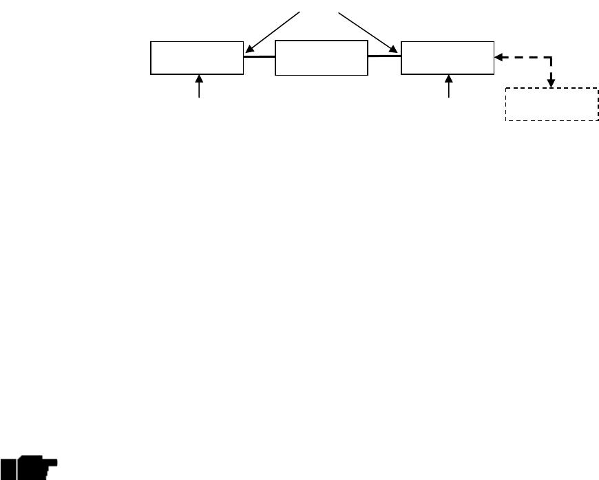
Exalt Communications Inc.
EX-2.4i Installation and Maintenance Manual
Page 35
MAN-002400, Revision 001
2005-12-01
Figure B-1: Basic Back-to-Back Test Configuration
After connecting and powering one, the front panel LEDs can be observed to verify that the Link
and Status LEDs are both green. If they are green, the radios are communicating and all radio-
related alarm conditions are normal.
It can be beneficial to have a computer to verify configuration in case of red LEDs or to pre-
configure the radio as desired for operation. Follow the instructions from the product manual on
how to connect the computer and configure the radio.
Alternatively, you may reset the radios to factory default configuration, which is performed by
holding the RMT button down while powering up. Hold the button down for approximately 5
seconds while applying power, and the radio is reset to factory default configurations. Perform
the reset for both ends, and the system should be operational in it’s default state. At this point,
you may reconfigure the radio, as necessary.
Note: If you have pre-configured the radios, the factory reset procedure will reset
the majority of your configurations. Do not reset the radios unless you have a
record of the desired configuration, or have downloaded the configuration file
from the radio first.
B-3 Specification Performance Verification
The specification performance verification is a more detailed test that allows you to verify that
the radio’s output power and threshold specifications are being met. This is typically a test that
would only be performed in a troubleshooting scenario, but can be performed before installation
if you wish to have a detailed record or be extremely certain of the radio performance before
installation.
This test is identical to the basic test, but in place of the fixed attenuation, it requires the use of
calibrated variable attenuation, or a set of calibrated fixed attenuators, or a combination of both,
adding to a total attenuation value of 120dB, as measured at the operating frequency of the radio
(roughly 2.4 GHz, in this case). In addition, a voltmeter or computer is also required.
Connect the system as in figure B-1, using the combination of fixed and variable attenuation in
between the radio’s RF ports. Connect the voltmeter to either radio’s RSL measurement port and
the associated reference ground connection.
Radio Radio
Attenuation
(
60-90dB
)
RF Ports
Power
(
connect last
)
Power
(co
nn
ec
t l
as
t
)
Computer
Console Port
Serial Port

Exalt Communications Inc.
EX-2.4i Installation and Maintenance Manual
Page 36
MAN-002400, Revision 001
2005-12-01
In this test, it is highly desirable to RF cables that are pre-tested, known good and known loss at
the operating frequency. If the cables are short (in the range of 6 feet or less), you can estimate
the loss, including connectors, to be less than 1dB each. The estimate of cable loss is critical to
the overall confidence of the measurements made in this test.
There are two critical specifications that can be tested in this configuration:
- RF output power
- Radio receiver threshold
To measure output power, simply insert any value of attenuation between the radios between 60
and 90dB. Make sure that both of the radio’s RF output power settings are at maximum. Using
the voltmeter, measure RSL in both directions. The RSL measured value should match the
appropriate value in accordance to the inserted attenuation. Such as:
RSL = RF Output Power – cabling losses – total attenuation
You can further verify output power by adjusting output power using your computer (in
administration mode) and evaluate the corresponding change to the RSL measurement.
For threshold testing, the key is to insert a measured amount of loss that is close to, but not
exceeding the radio’s specified system gain. System gain is the difference between RF output
power and receiver threshold. At your selected modulation and bandwidth settings, determine the
specified threshold performance, and choose a value of attenuation (including cable losses) that
adds to roughly 5 to 15dB less than the system gain.
For example, if the threshold for your measurement is -85dBm, the output power is +27dBm, so
the System Gain is 112dB. Choose a value of total attenuation in the range of roughly 100-
105dB. Once this attenuation is inserted, verify RSL readings as in the first step, and then, using
your computer, adjust radio output power attenuation in 1dB steps until the receiving radio (the
one whose output power you are not adjusting) Link LED turns from green to yellow. This
would indicate that threshold has been reached. At this point, verify the equation for system gain
using the new output power level setting and verify that the threshold performance is meeting the
published specification.
Due to the variables involved in this test, you may read a measurement that is 1 to
as much as 2dB off of the expected value. It should be of no concern unless the
value is more than 3dB worse than expected.
Once threshold is verified in this direction, you may repeat the process in the opposite direction
by adjusting RF output power of the other radio.
You may wish to perform threshold measurement tests for all combinations of bandwidth and
modulation that you are using – especially if testing for the purposes of troubleshooting. It
should not be necessary to vary center frequency, as this does not typically have any impact on
Exalt Communications Inc.
EX-2.4i Installation and Maintenance Manual
Page 37
MAN-002400, Revision 001
2005-12-01
system gain performance – however, any combination of settings may be tried to gain confidence
in the radio performance parameters.

Exalt Communications Inc.
EX-2.4i Installation and Maintenance Manual
Page 38
MAN-002400, Revision 001
2005-12-01
Appendix C - DC Coupler for Antenna Alignment
C-1 Introduction
One challenge associated with an all-indoors radio construction is the alignment of the antennas.
It can sometimes be challenging to place the radio near the antenna alignment personnel, and can
also be challenging to run a separate set of wires for the voltmeter to be in view of the alignment
personnel. If any of the conventional methods that have been mentioned in the manual are
difficult to achieve, one of the simplest methods to use is to employ the use of a DC coupling
system as a temporary test configuration exclusively for the use of aligning the antennas.
This type of system simply couples the DC voltage associated with RSL measurement at the
radio location, over the RF transmission line, up to the antenna port.
You must remove all DC-blocked lightning arrestors in the transmission
system prior to applying the DC coupler system. Failure to do so can result
in electric shock and/or damage the lightning arrestors and/or other
equipment.
C-2 Items Required
The following items are needed for the DC coupling system, per radio end (double the quantities
of these items for a complete link for simultaneous use at both ends):
- 2ea DC Couplers: Mini-Circuits ZNBT-60-1W
- 1ea BNC male-male extension cable: Pomona 2249
- 1ea BNC Female to Mini Bantam (stackable Pin-tip plugs): Pomona 3221
- 1ea BNC Female to Banana Male: Pomona 5268*
- 1ea Digital Volt Meter
*This type of plug is typical for most professional hand-held Digital Volt Meters (DVM). However,
verify that your DVM can accept this type of Banana connector. If not, you may need a different part
number or adapter to connect to your DVM.
C-3 Interconnection
Connect the items as shown in Figure C-1. For the coupler installation, make certain that the DC
side of the coupler is facing away from the radio and away from the antenna – towards the RF
transmission line system. Using the BNC adaptors and cables, attach the radio end DC coupler to
the RSL port on the radio, and the antenna end DC coupler to the DVM that the antenna
alignment personnel will use.
!
CAUTION
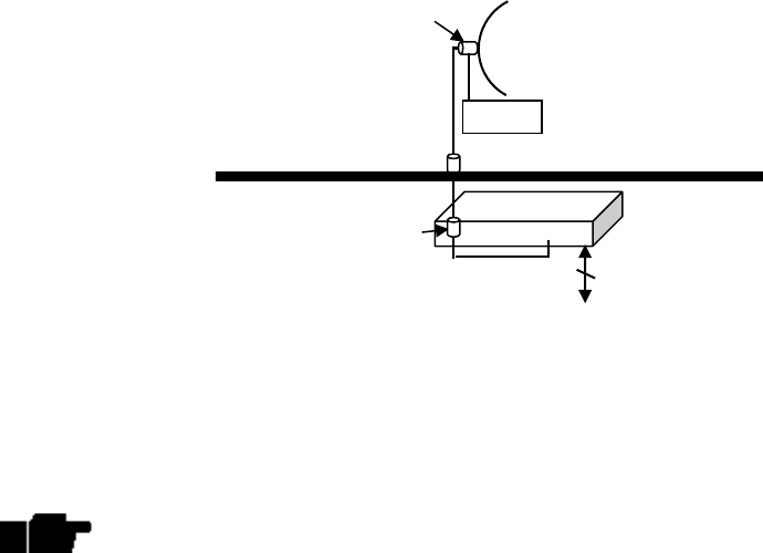
Exalt Communications Inc.
EX-2.4i Installation and Maintenance Manual
Page 39
MAN-002400, Revision 001
2005-12-01
Figure C-1: DC Coupler Interconnection
The DC voltage from the RSL port is now coupled to the transmission line system between the
radio and the antenna, and is available at the antenna location. This allows the antenna alignment
personnel to view the DVM output directly while adjusting the antenna.
Always remove the DC couplers and associated wiring, at both the radio end and
the antenna end, after antenna alignment is complete.
Jumper cable or adapter (in place of lightning arrestor)
Primary Transmission Line
Antenna
Secondary Transmission Line
Radio
Structure Penetration
Power/Data/Interfaces
Coupler (DC side toward radio)
Coupler (DC side toward antenna)
DVM
To RSL port