Exalt Wireless 104P90M 4.9GHz Point to Point Fixed Link Radio User Manual i manual LMAfinal
Exalt Communications Inc. 4.9GHz Point to Point Fixed Link Radio i manual LMAfinal
UserManual.wiki
>
Exalt Wireless
>
104P90M User Manual
>
i Manual
Contents
1.
i Manual
2.
Manual
i Manual
Navigation menu
Upload a User Manual
Namespaces
Wiki Guide
HTML
PDF
Info
Views
User Manual
Discussion / Help
Navigation
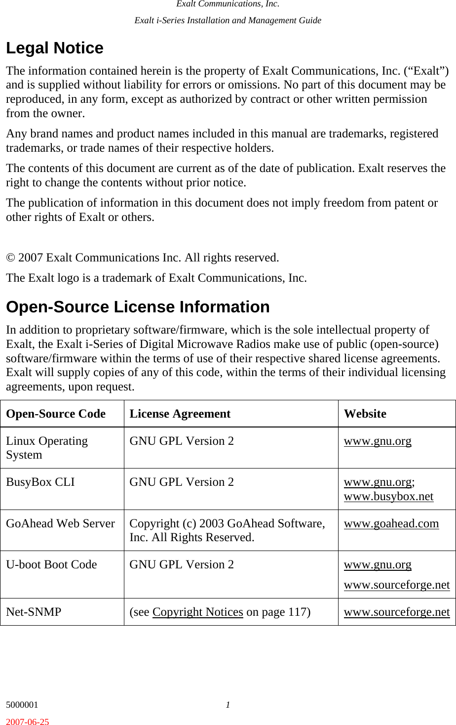
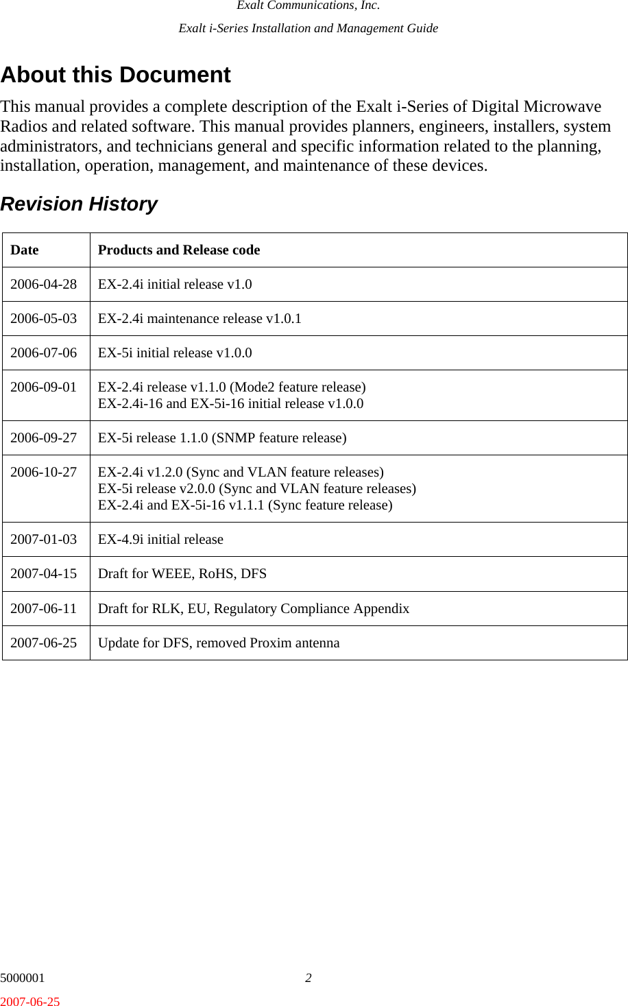
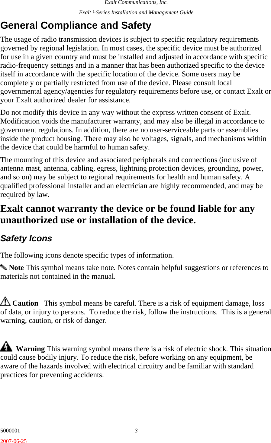
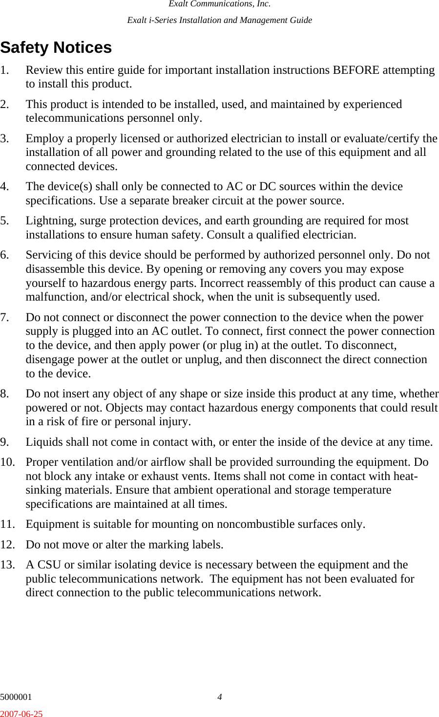
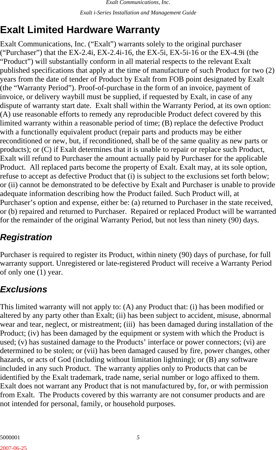
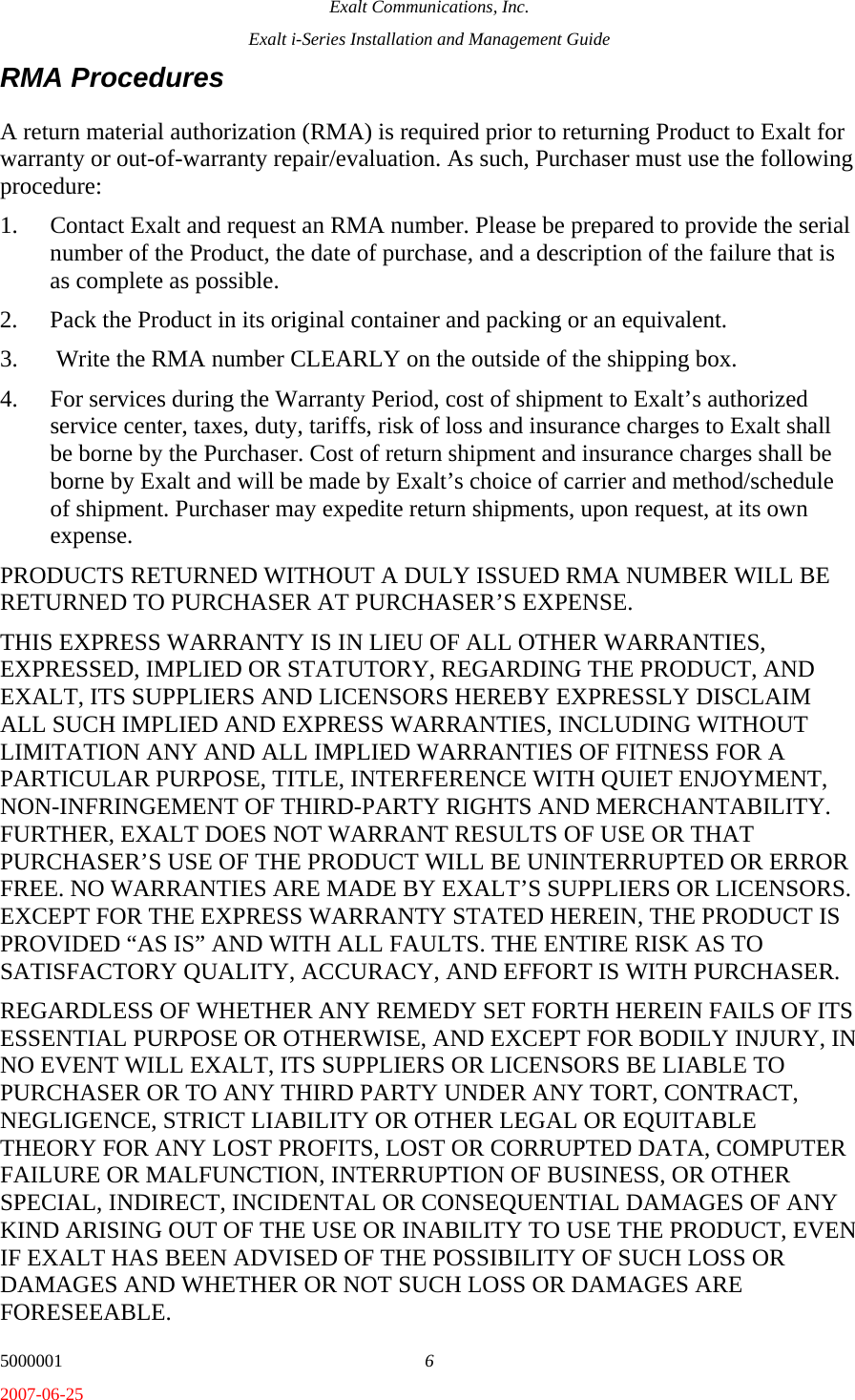
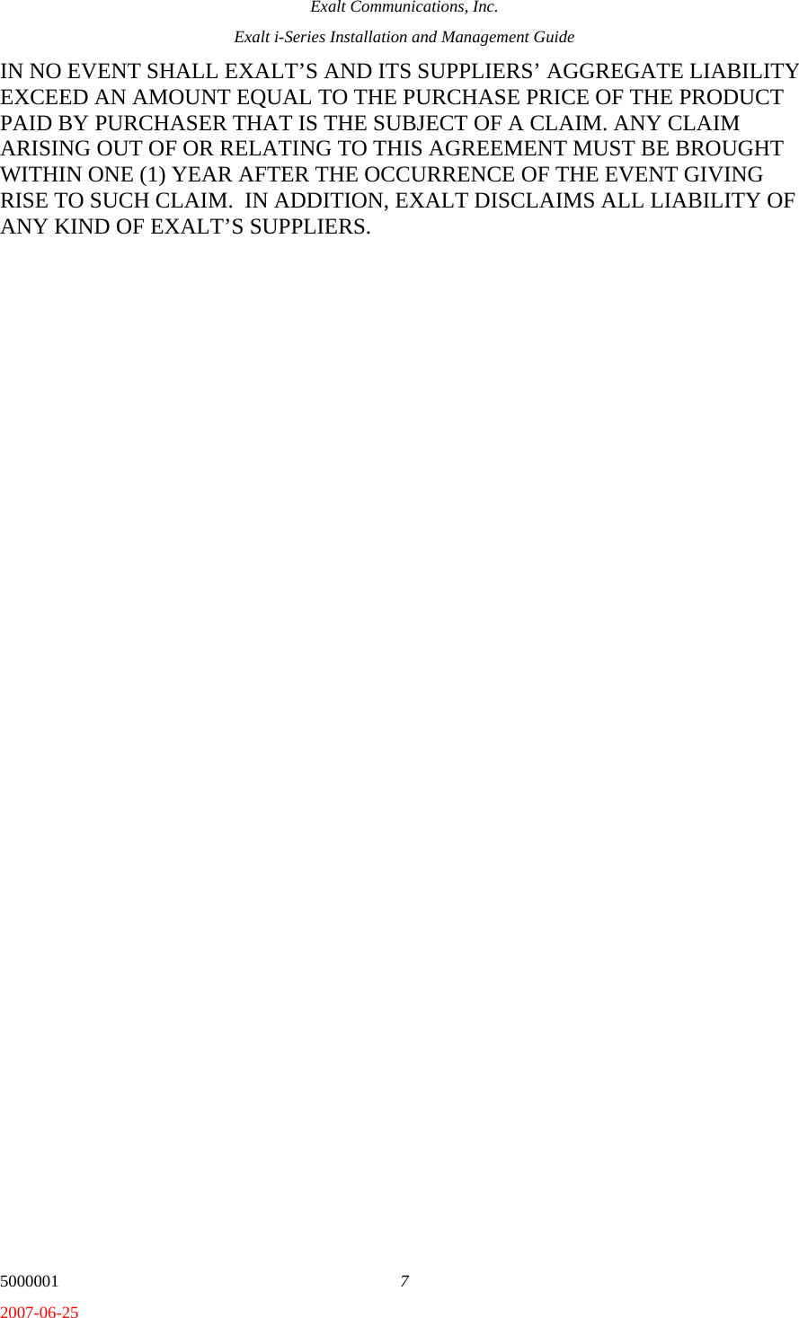
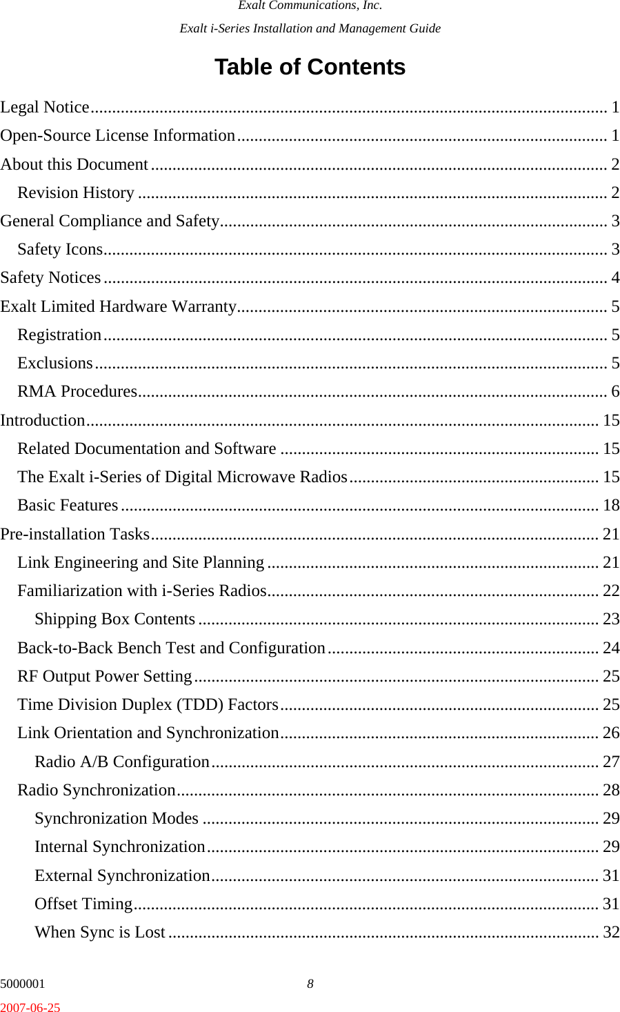
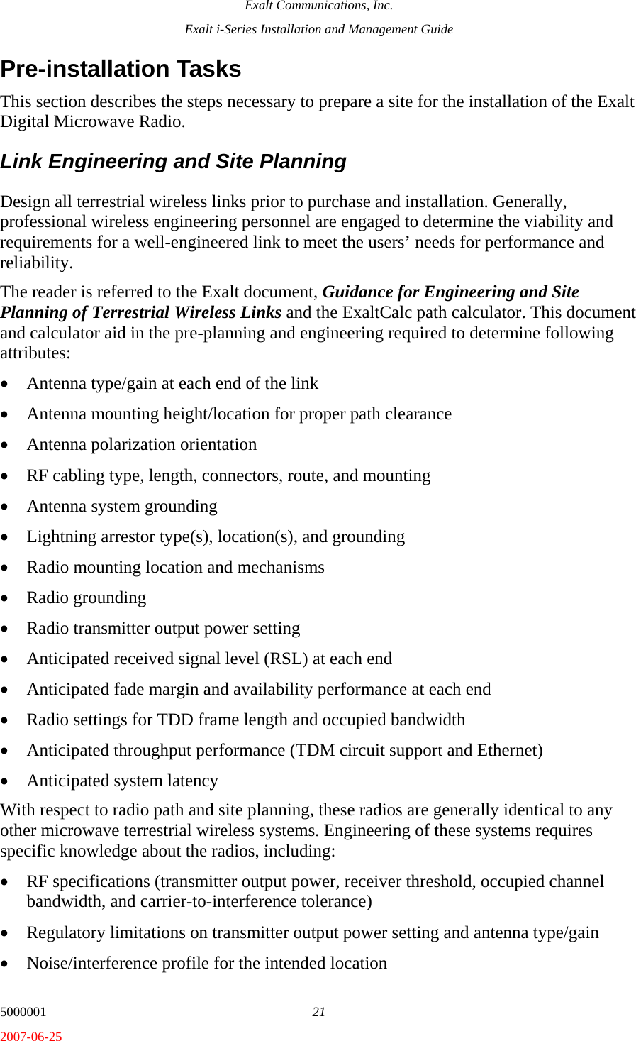


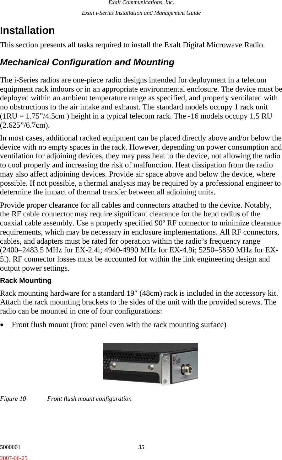
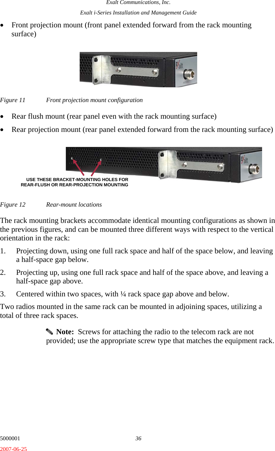
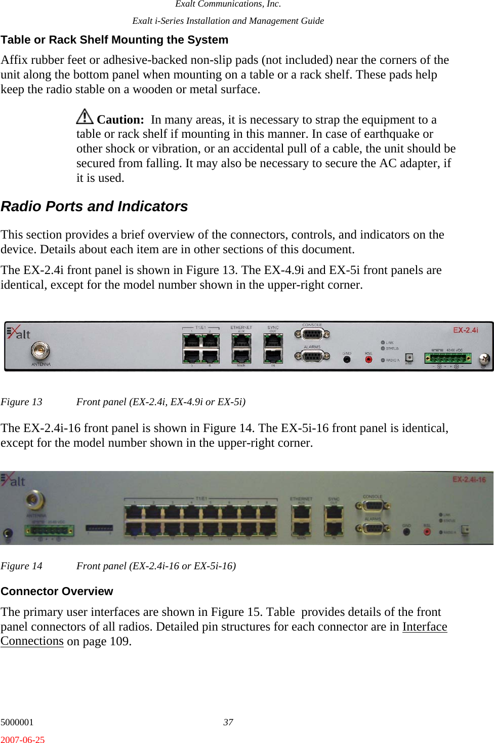
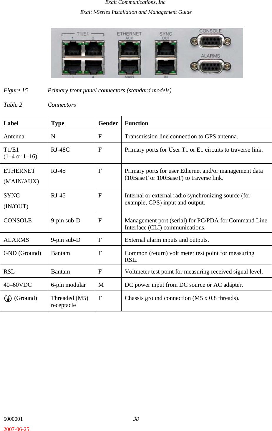
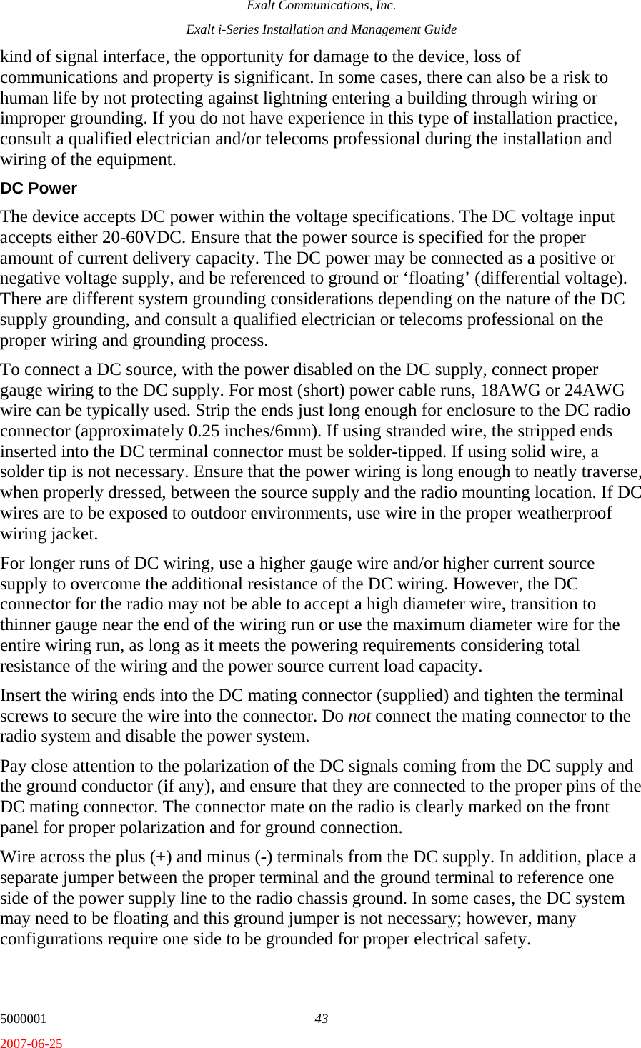
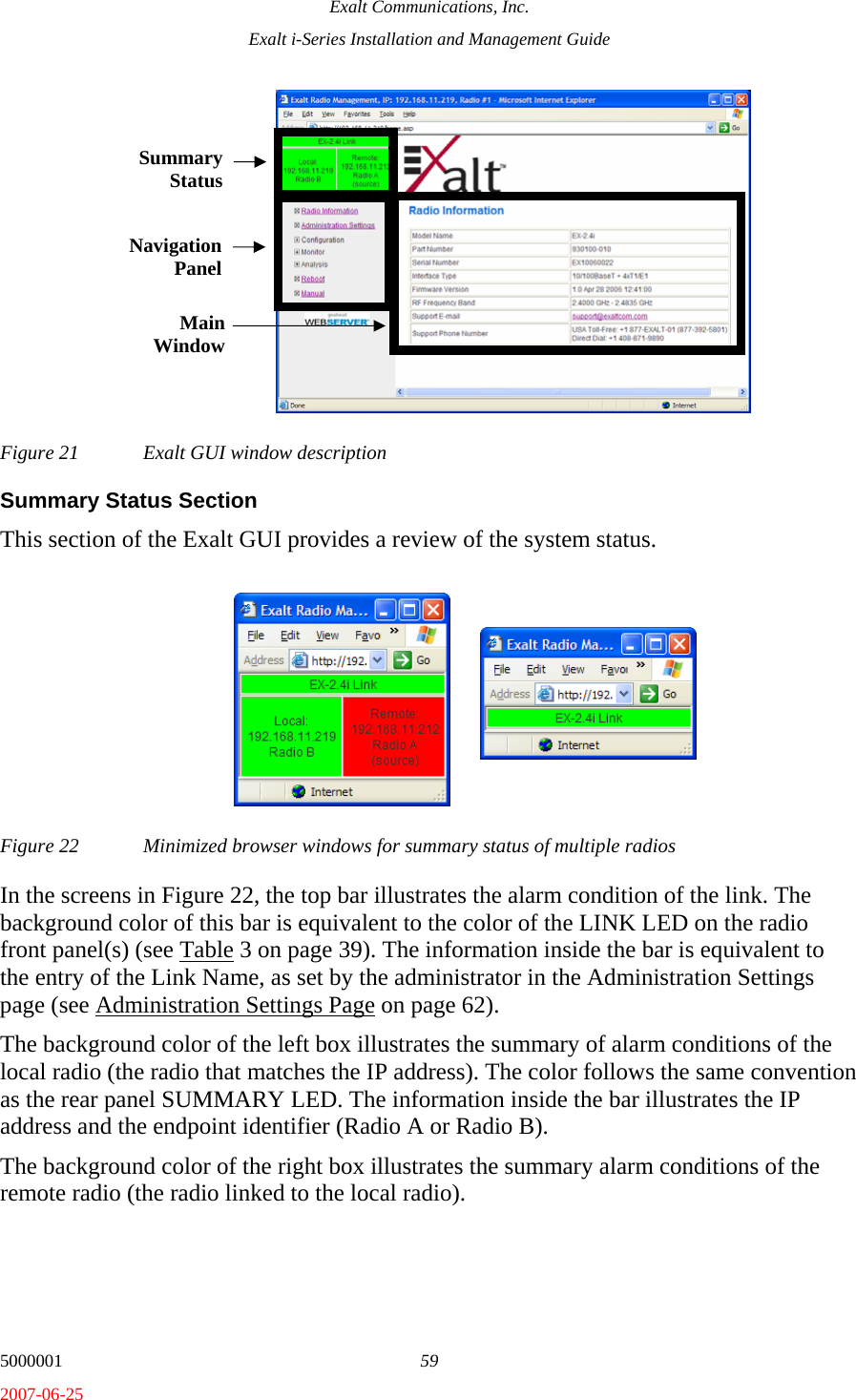
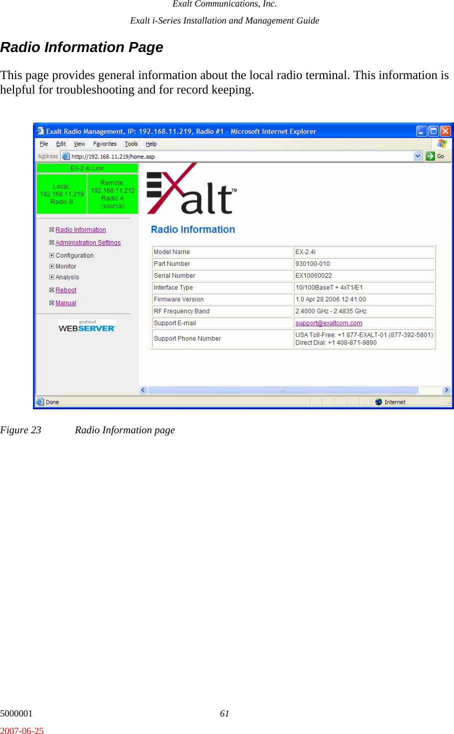
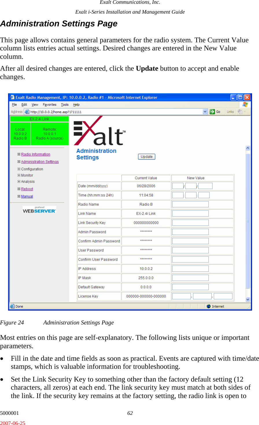
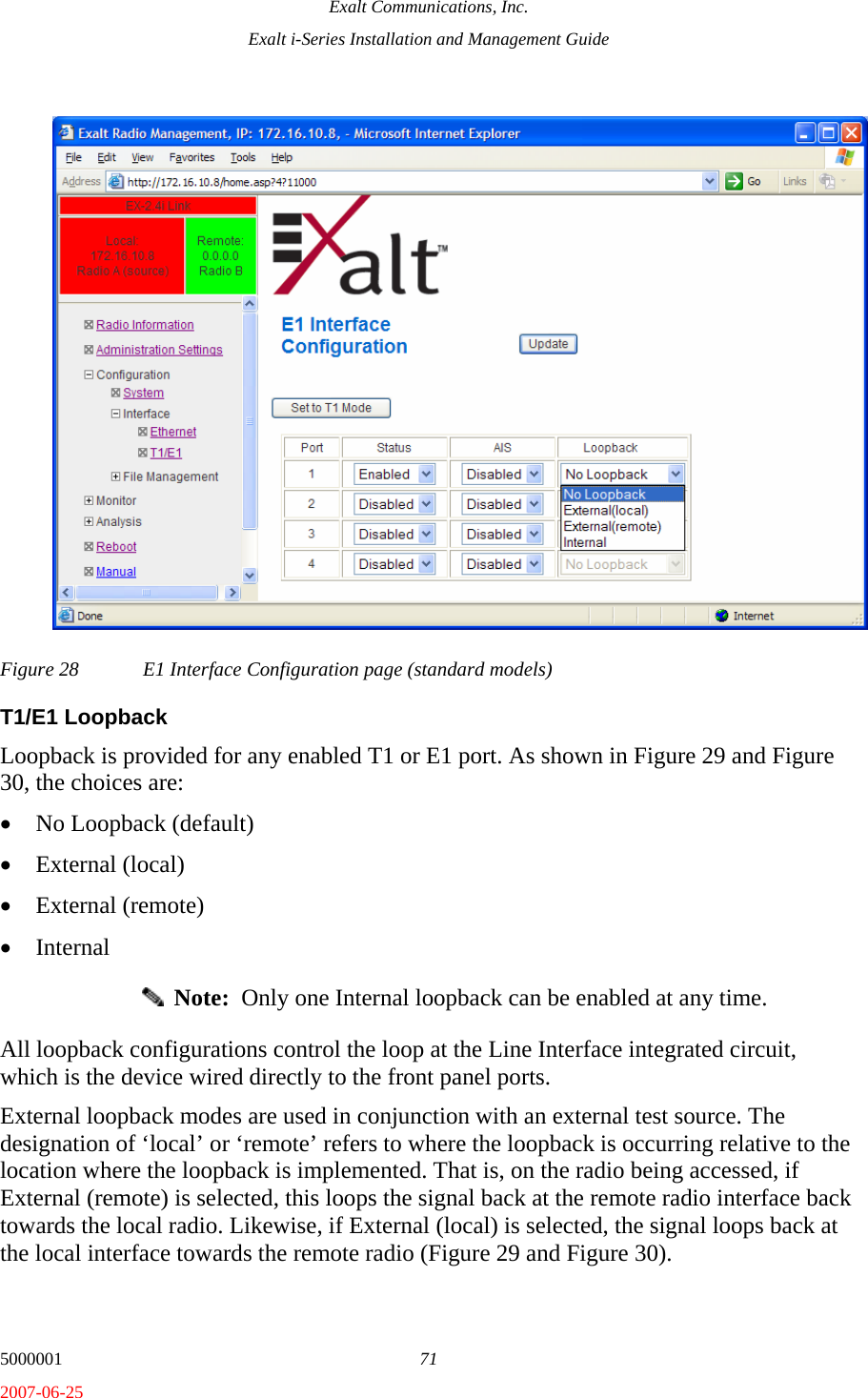
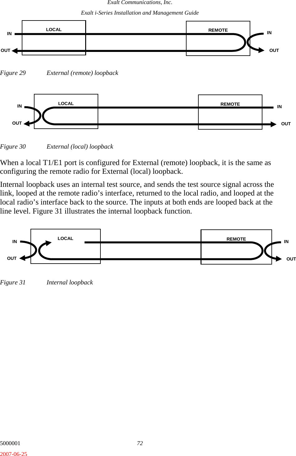
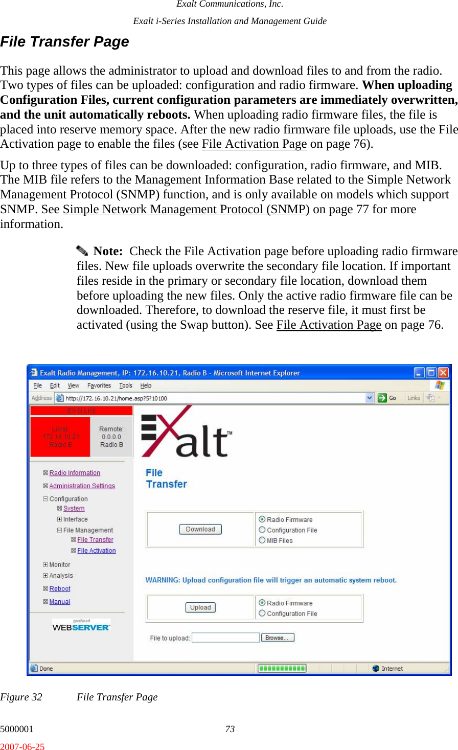
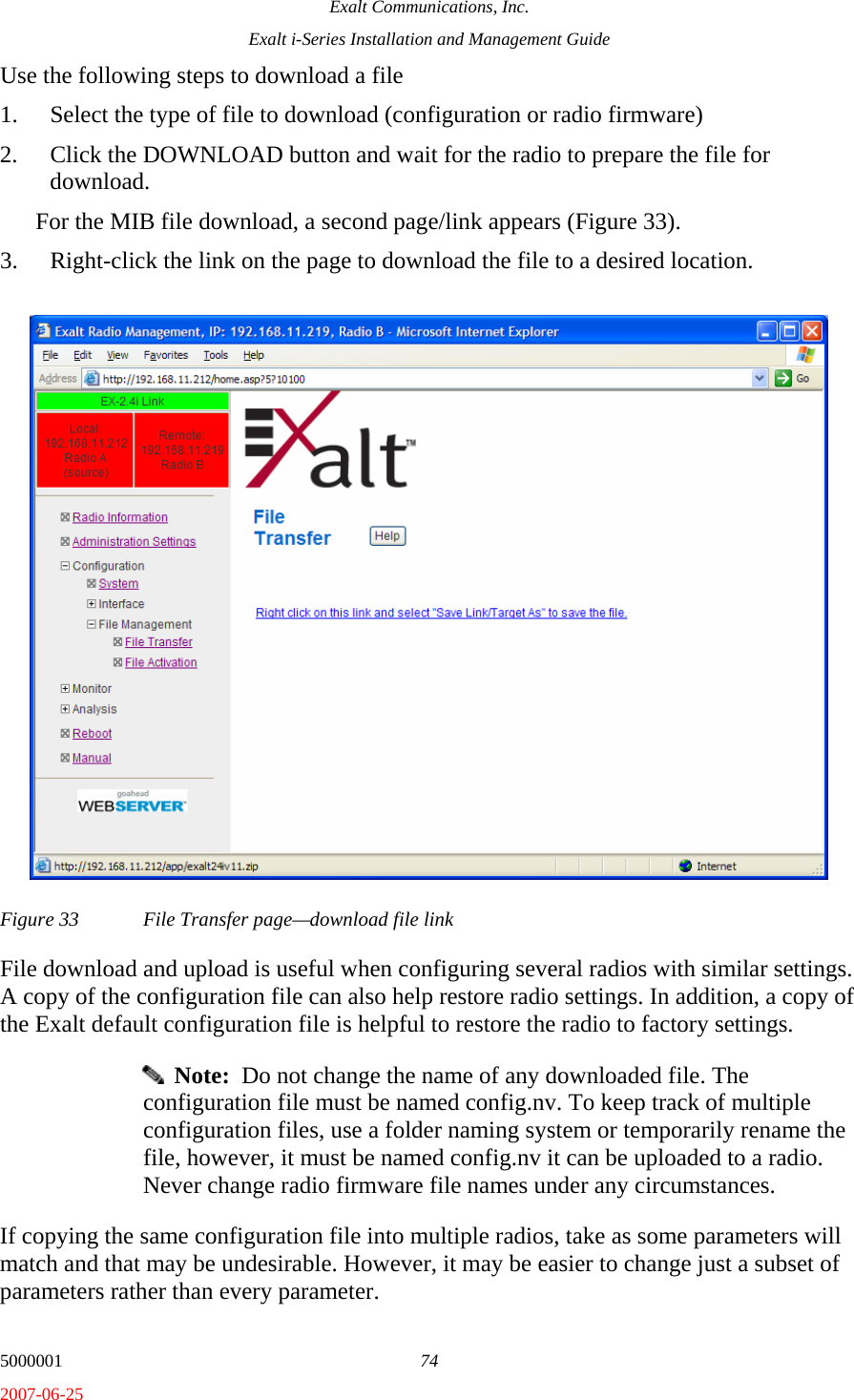
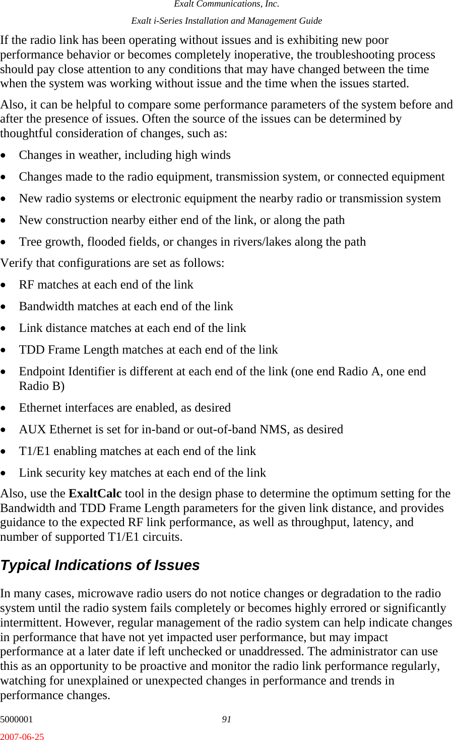
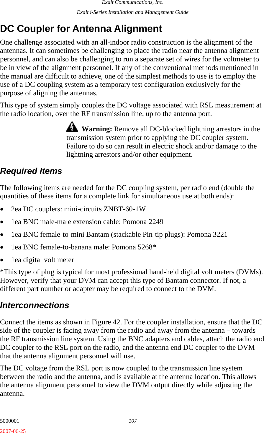
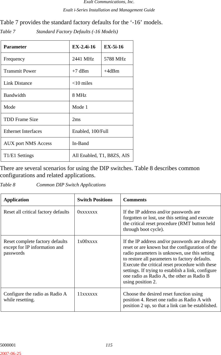

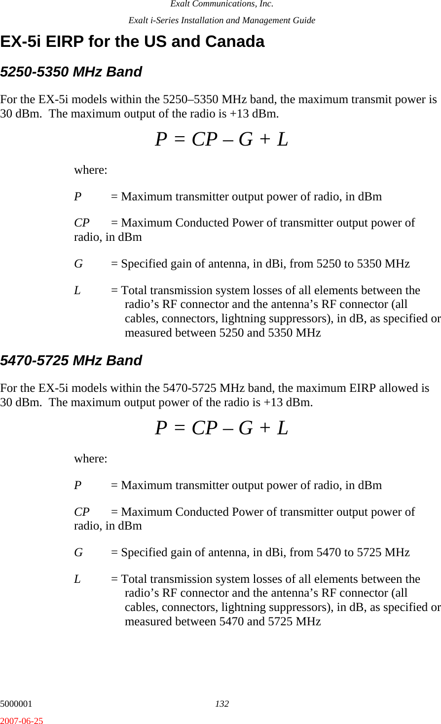
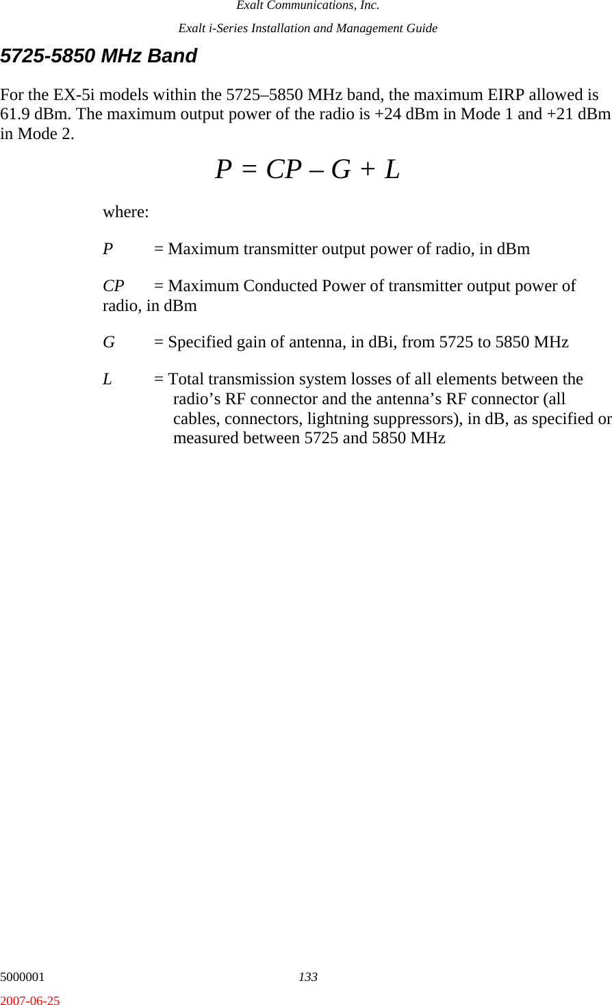
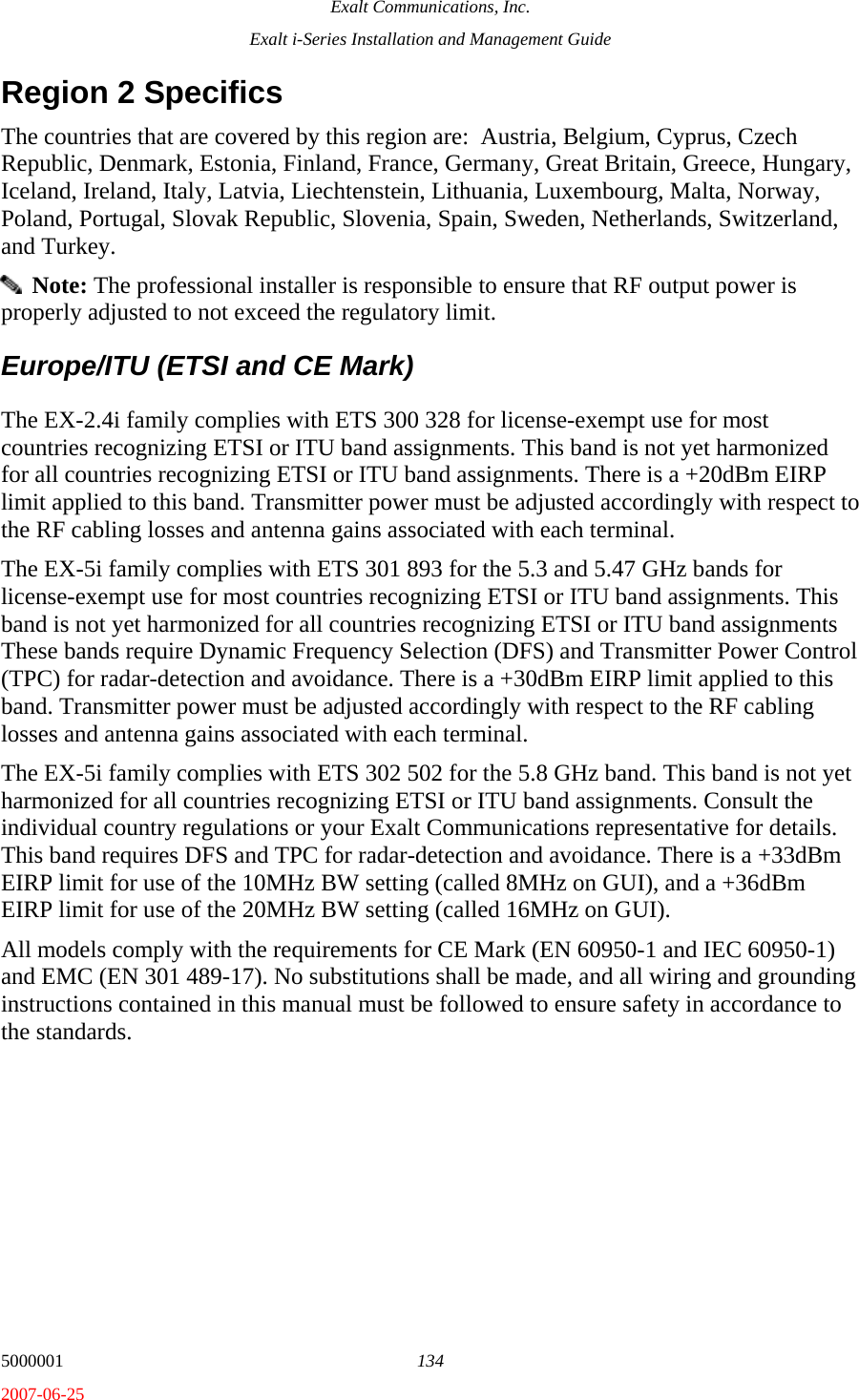
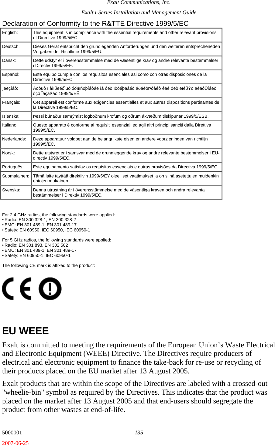
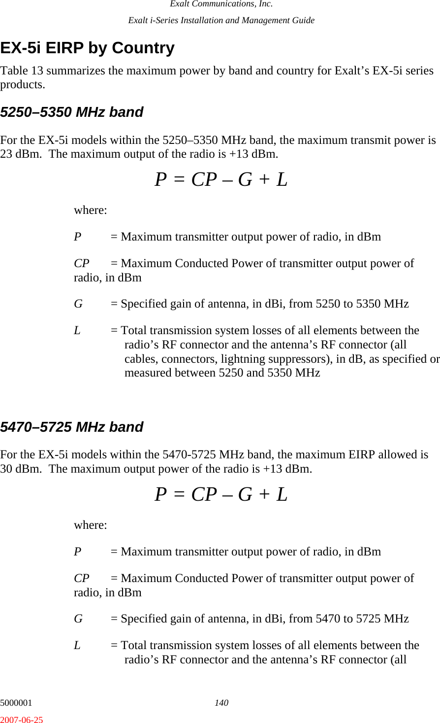
![Exalt Communications, Inc. Exalt i-Series Installation and Management Guide 5000001 131 2007-06-25 Industry Canada (IC), Canada on page 128. EX-2.4i EIRP for the USA and Canada For the EX-2.4i models, the maximum EIRP allowed is +52.2 dBm. The maximum conducted power of the radio is +27 dBm for Mode 1 and +24 dBm for Mode 2. The following formula is used to determine the output power: P = CP – [(G-6)/3] + L where: P = Maximum transmitter output Power of radio, in dBm CP = Maximum Conducted Power of transmitter power of radio, in dBm G = Specified gain of antenna, in dBi, from 2400 to 2483.5 MHz L = Total transmission system losses of all elements between the radio’s RF connector and the antenna’s RF connector (all cables, connectors, and lightning suppressors), in dB, as specified or measured between 2400 and 2483.5 MHz EX-4.9i EIRP for the USA and Canada For the EX-4.9i model within the 4940–4990 MHz band, the maximum EIRP allowed is +50 dBm. The maximum conducted power of the radio is +24 dBm for Mode 1 and +21 dBm for Mode 2. The following formula is used to determine the output power: P = CP – G + L where: P = Maximum transmitter output power of radio, in dBm CP = Maximum Conducted Power of transmitter output power of radio, in dBm G = Specified gain of antenna, in dBi, from 4940 to 4990 MHz L = Total transmission system losses of all elements between the radio’s RF connector and the antenna’s RF connector (all cables, connectors, lightning suppressors), in dB, as specified or measured between 4940 and 4990 MHz](https://usermanual.wiki/Exalt-Wireless/104P90M.i-Manual/User-Guide-826087-Page-133.png)