Exalt Wireless 105P25P Ex-i Series 5.8GHz Radio Module User Manual
Exalt Communications Inc. Ex-i Series 5.8GHz Radio Module Users Manual
UserManual.wiki
>
Exalt Wireless
>
105P25P User Manual
>
Users Manual
Contents
1.
Users Manual
2.
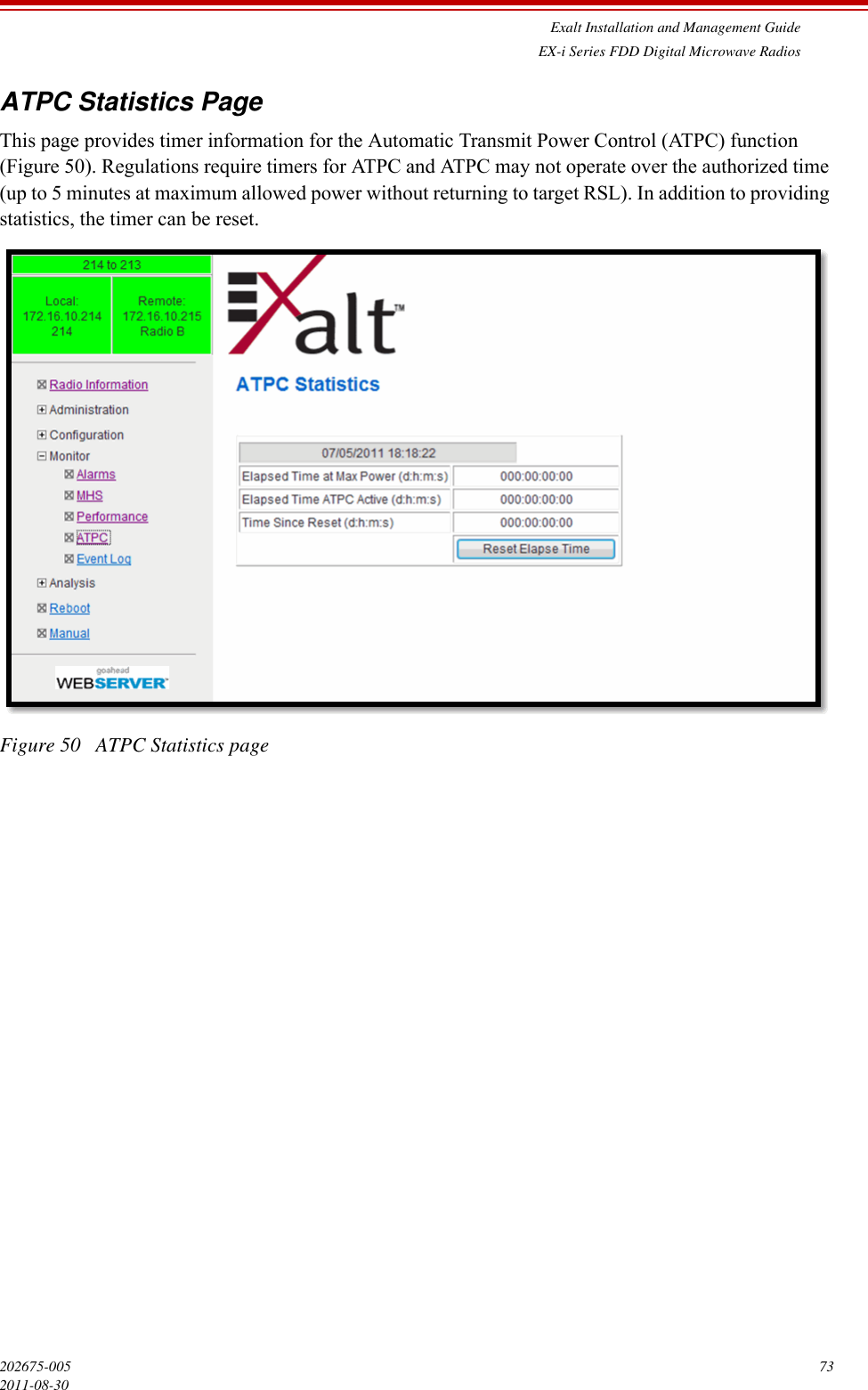
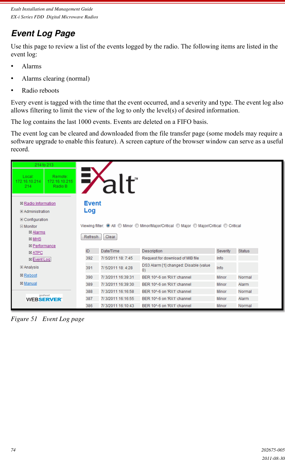
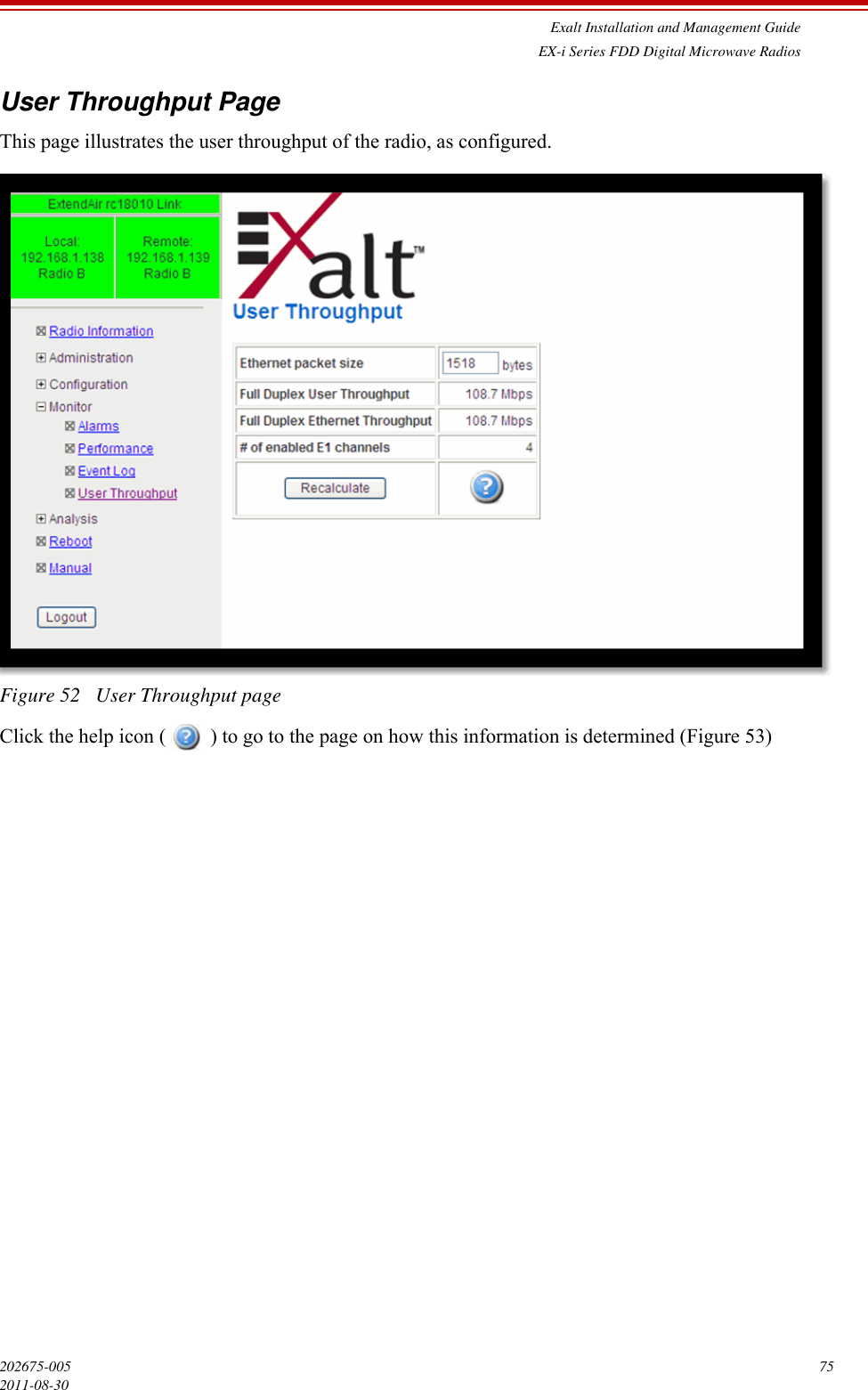
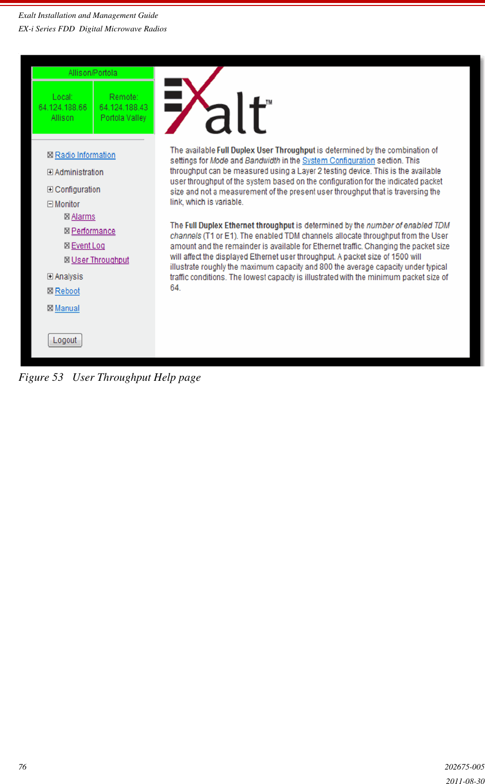
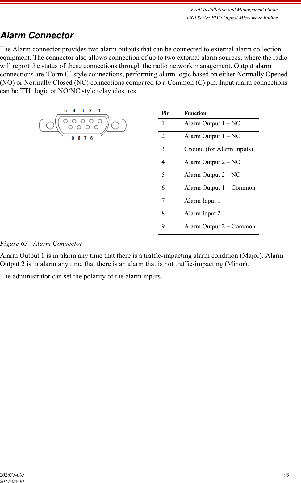
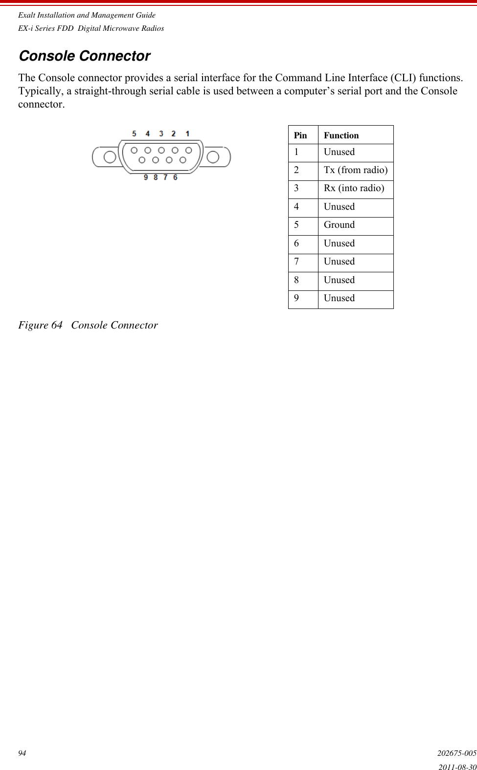
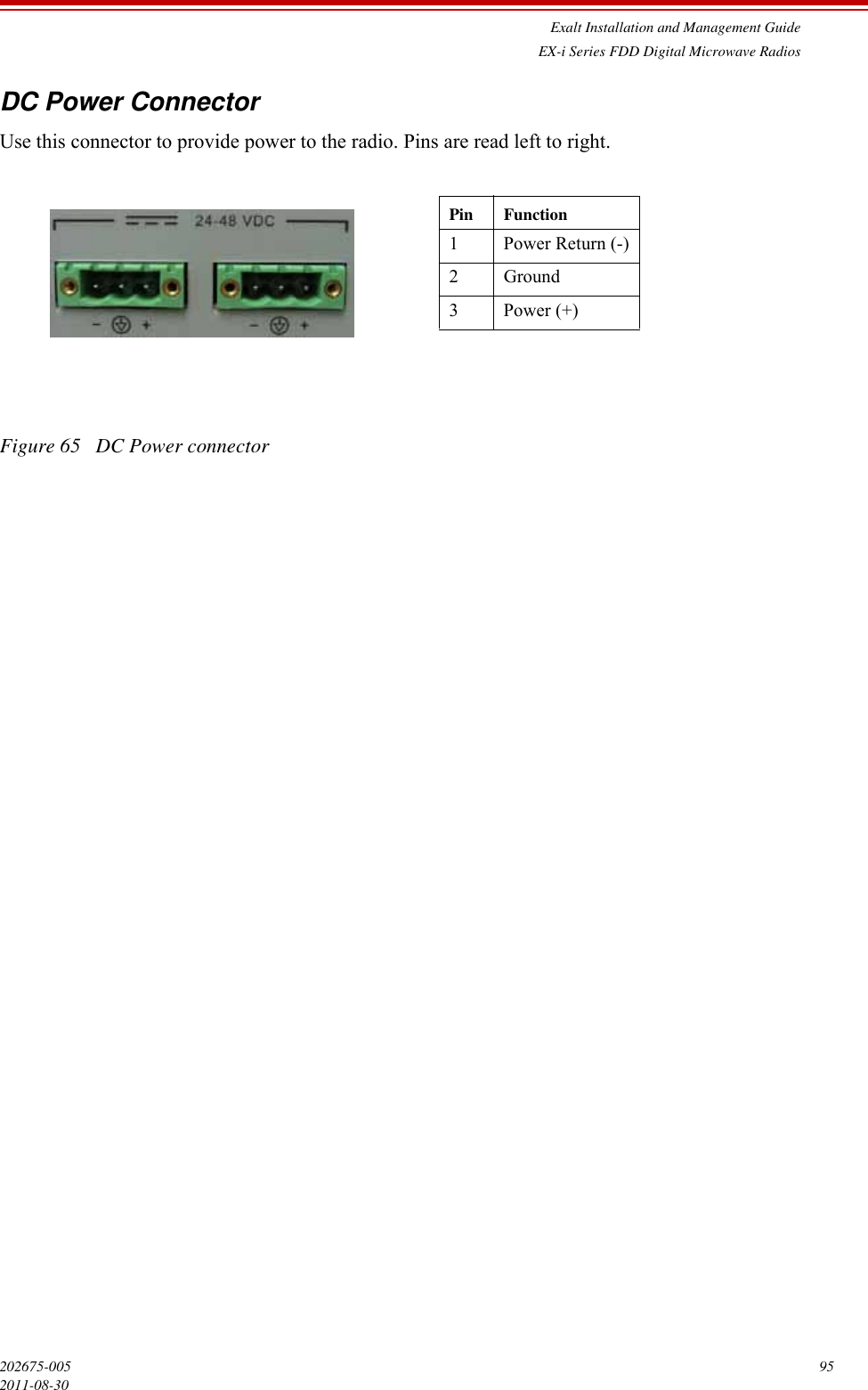
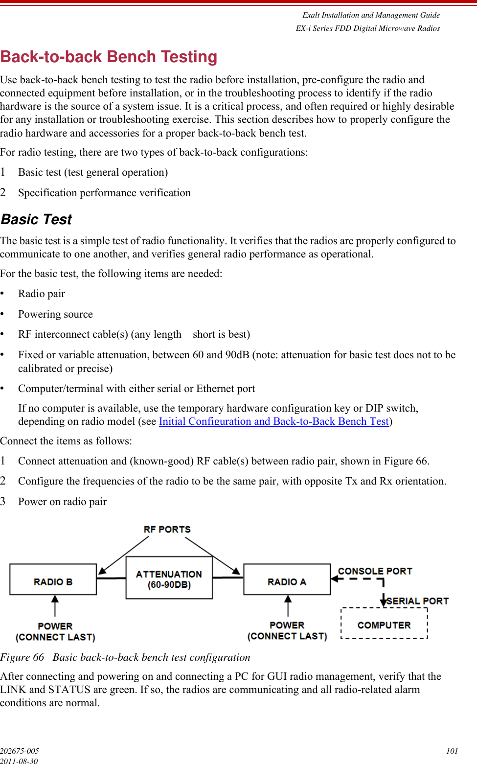
User Manual
Users Manual
Navigation menu
Upload a User Manual
Namespaces
Wiki Guide
HTML
PDF
Info
Views
User Manual
Discussion / Help
Navigation