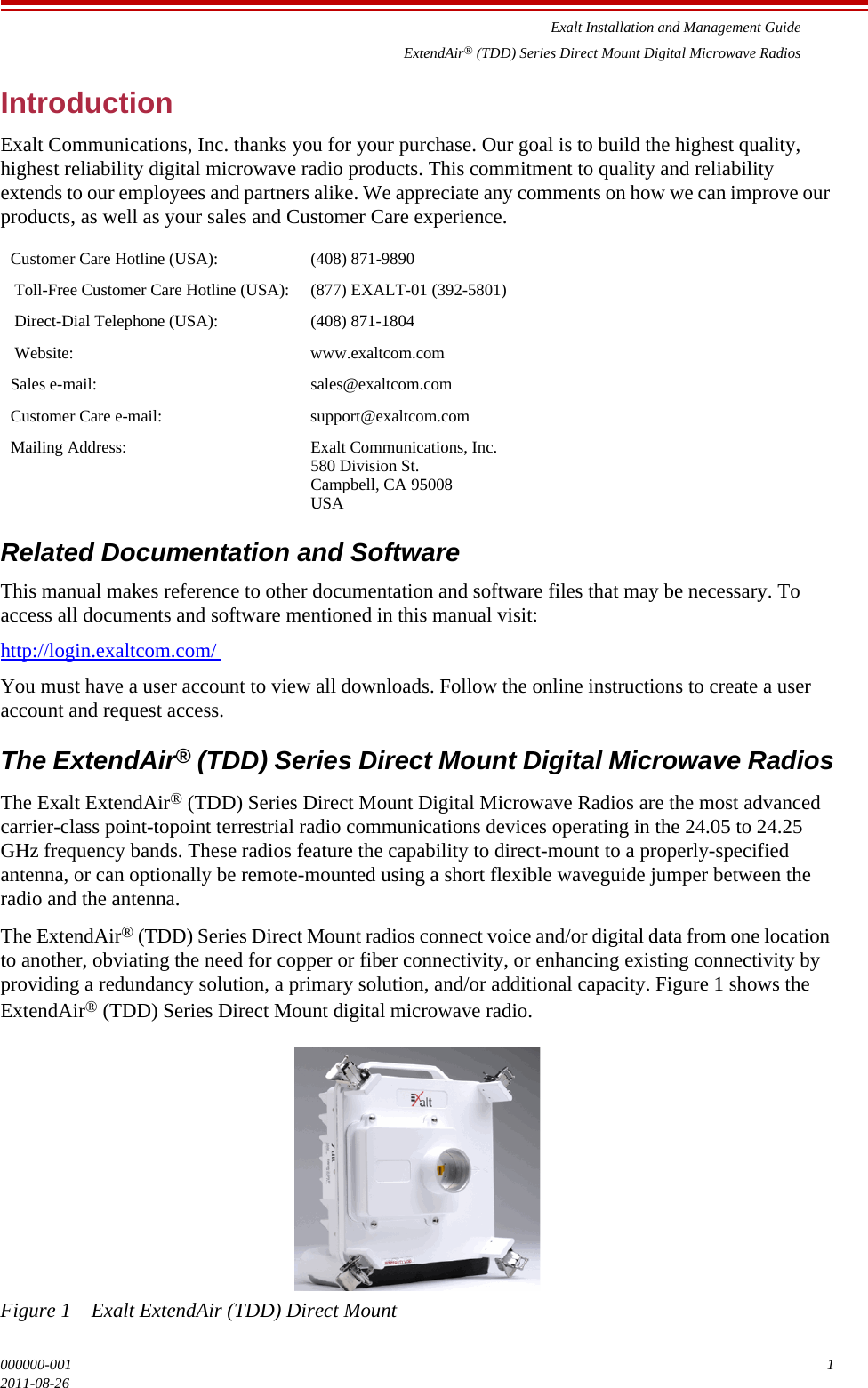
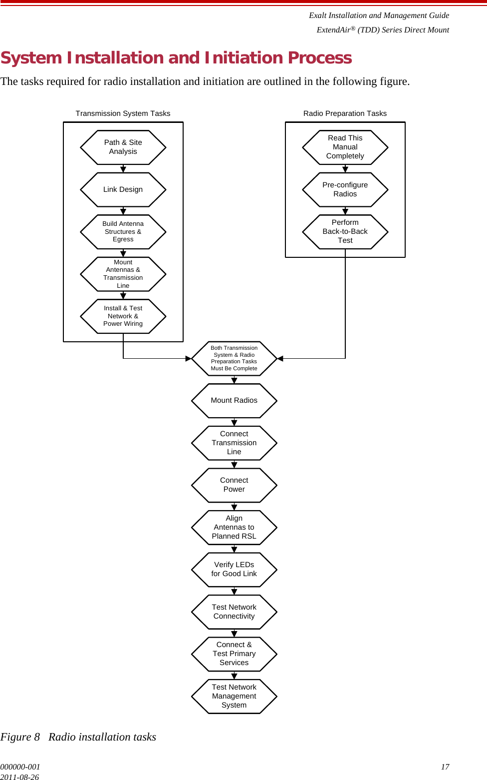
Exalt Wireless 124P05N 24GHz Radio User Manual
Exalt Communications Inc. 24GHz Radio Users Manual
UserManual.wiki
>
Exalt Wireless
>
124P05N User Manual
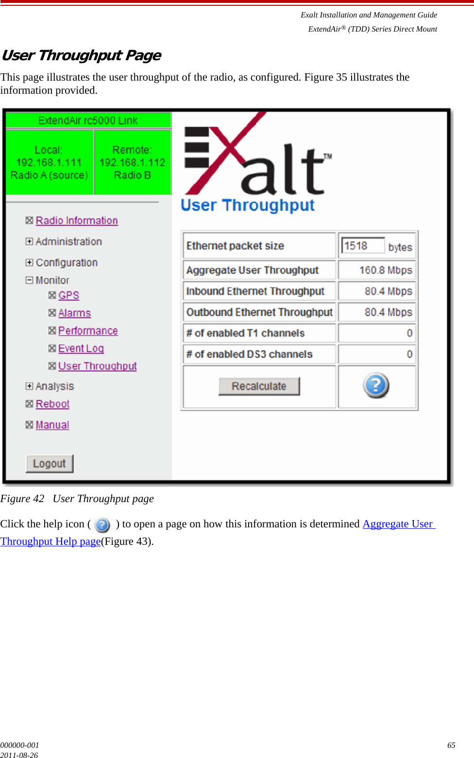
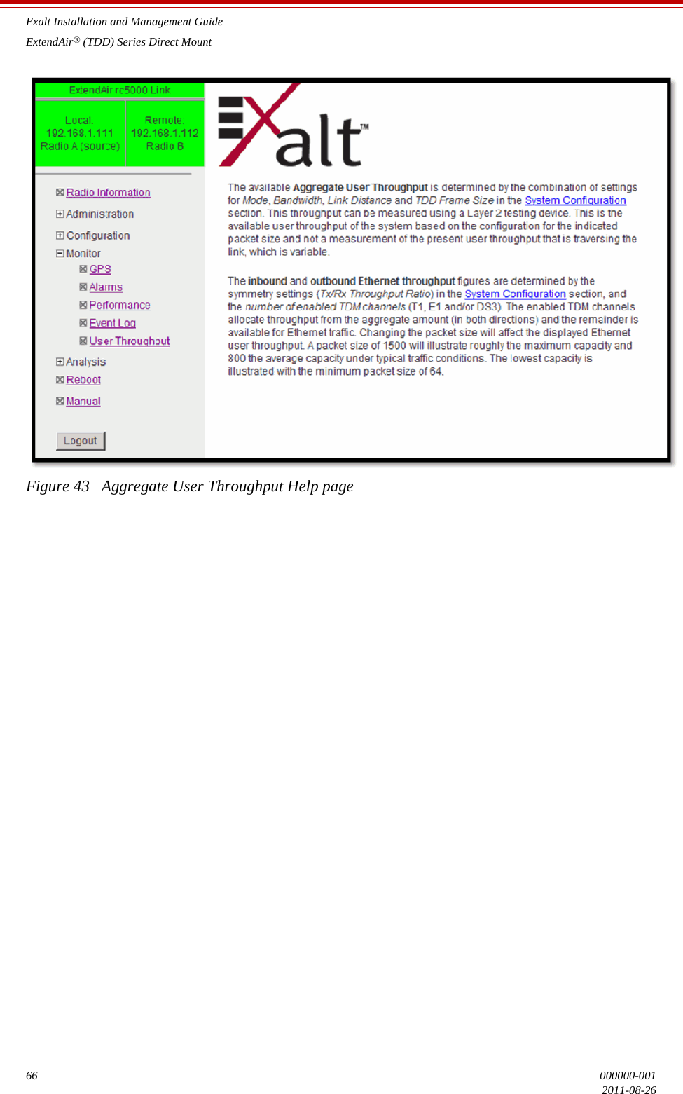
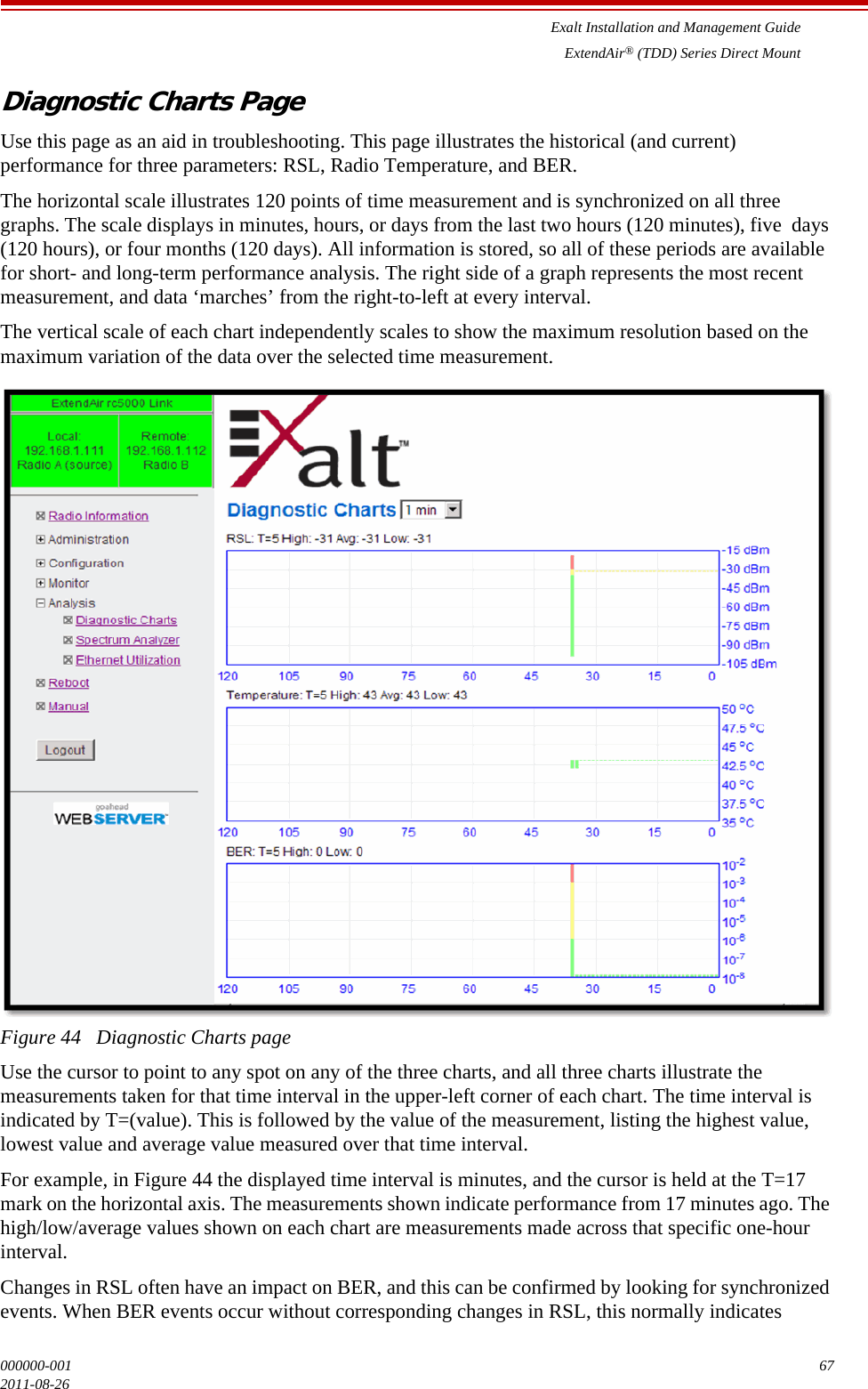
Users Manual
Navigation menu
Upload a User Manual
Namespaces
Wiki Guide
HTML
PDF
Info
Views
User Manual
Discussion / Help
Navigation