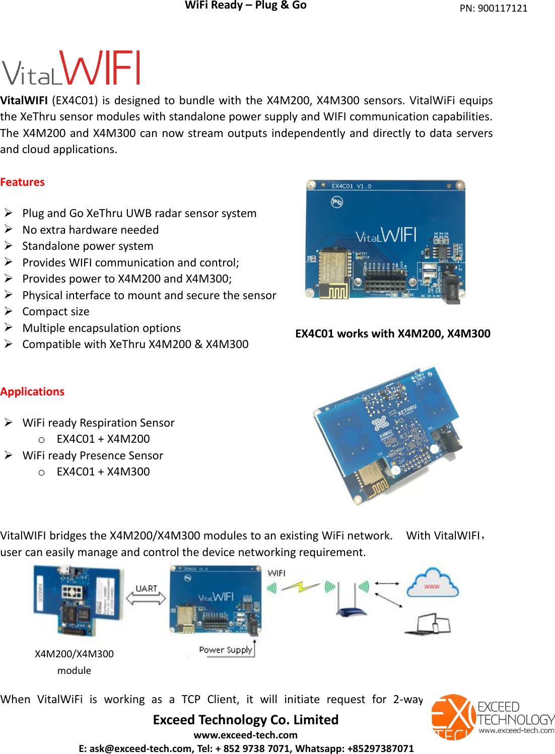
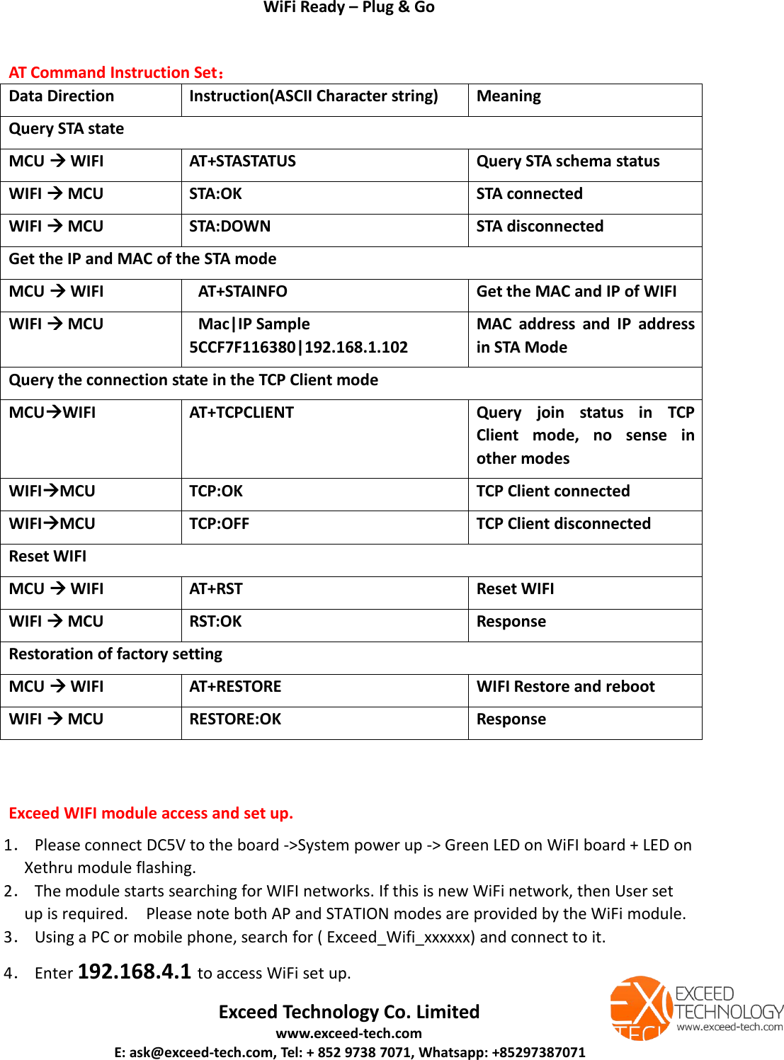
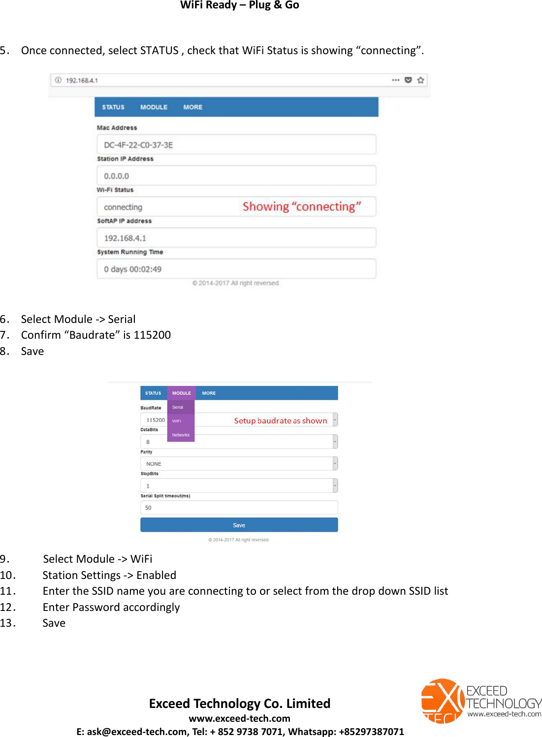
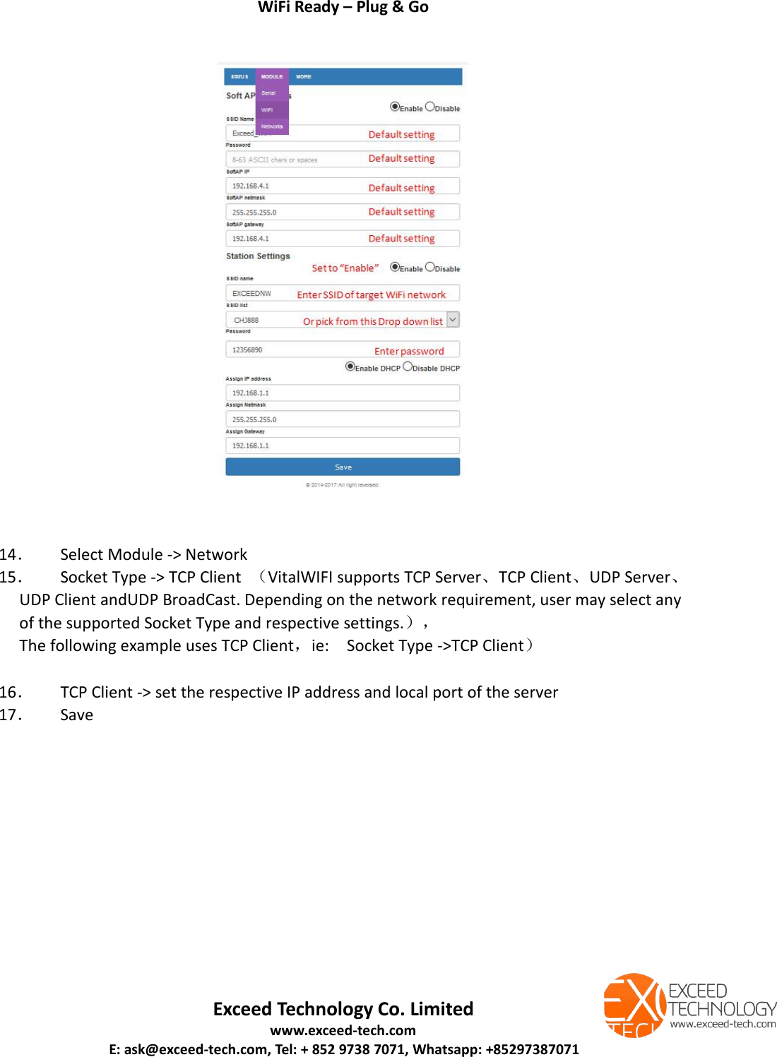
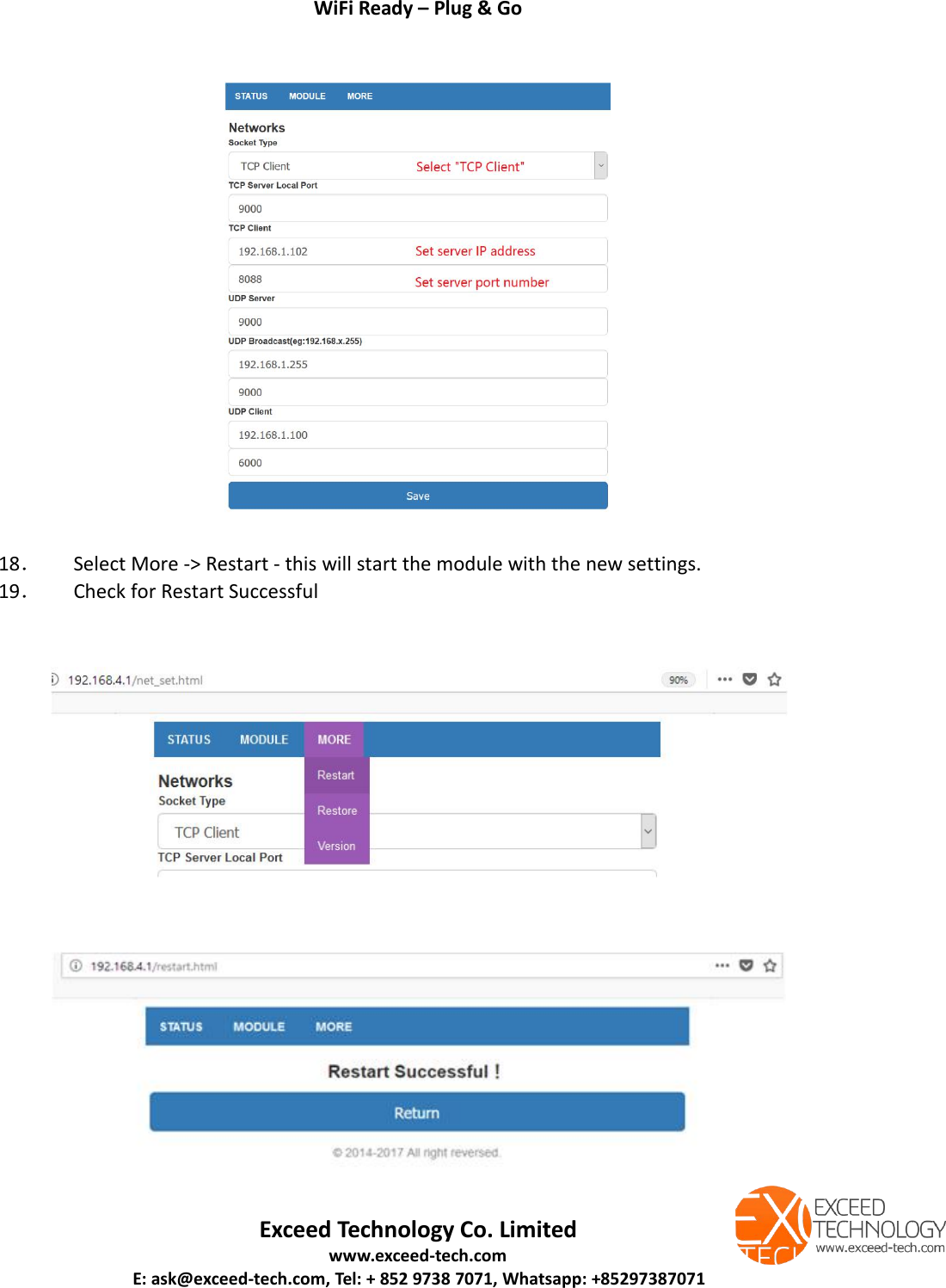
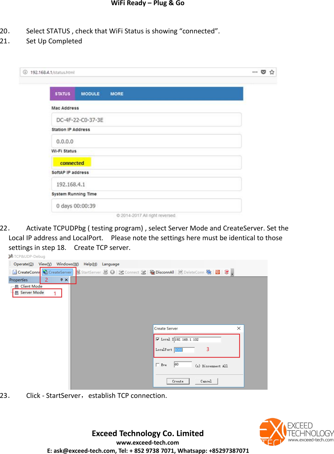
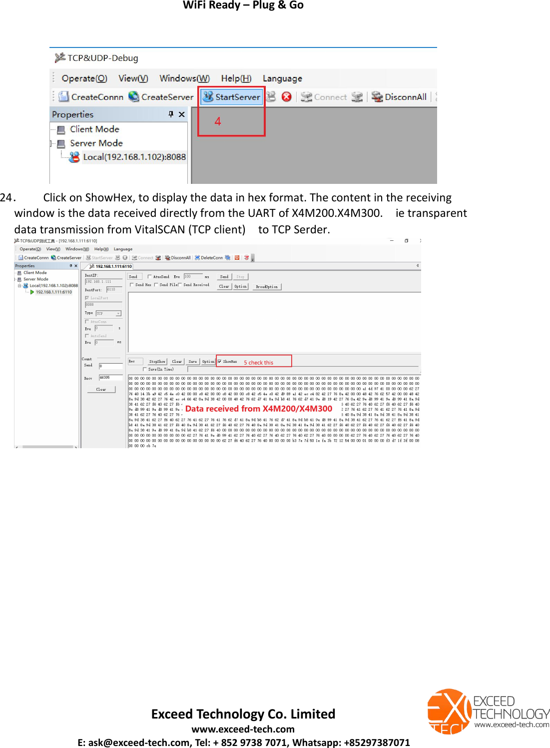
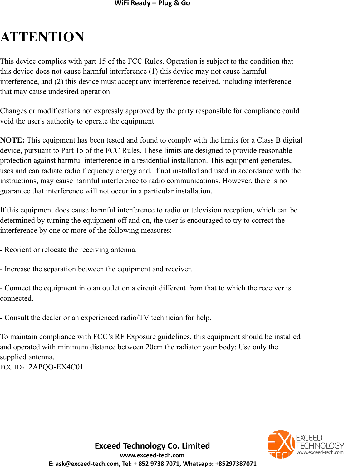
Exceed Technology EX4C01 Water leak detector User Manual

Shenzhen Exceed Technology Co.,Ltd. Water leak detector

User Manual

WiFi Ready – Plug & GoExceed Technology Co. Limitedwww.exceed-tech.comE: ask@exceed-tech.com, Tel: + 852 9738 7071, Whatsapp: +85297387071VitalWIFI (EX4C01) is designed to bundle with the X4M200, X4M300 sensors. VitalWiFi equipsthe XeThru sensor modules with standalone power supply and WIFI communication capabilities.The X4M200 and X4M300 can now stream outputs independently and directly to data serversand cloud applications.FeaturesPlug and Go XeThru UWB radar sensor systemNo extra hardware neededStandalone power systemProvides WIFI communication and control;Provides power to X4M200 and X4M300;Physical interface to mount and secure the sensorCompact sizeMultiple encapsulation optionsCompatible with XeThru X4M200 & X4M300ApplicationsWiFi ready Respiration SensoroEX4C01 + X4M200WiFi ready Presence SensoroEX4C01 + X4M300VitalWIFI bridges the X4M200/X4M300 modules to an existing WiFi network. With VitalWIFI,user can easily manage and control the device networking requirement.When VitalWiFi is working as a TCP Client, it will initiate request for 2-wayEX4C01 works with X4M200, X4M300PN: 900117121X4M200/X4M300module
WiFi Ready – Plug & GoExceed Technology Co. Limitedwww.exceed-tech.comE: ask@exceed-tech.com, Tel: + 852 9738 7071, Whatsapp: +85297387071connections with a TCP Server device. Upon successful connection, transparent transmissionbetween Server and Client is enabled. The server end could be a fixed IP from the Internet, or adevice within the network with an intranet IPPlug and Ready to useNo further hardware development required. Using the Vital-WIFI, the XeThru sensor modulescan now be managed via WIFI. Users only need to focus on developing the backend softwareinterfaces.Schematic diagramVitalWIF(EX4C01) is made up of DC-DC voltage converter, WIFI module,connectors and LED.DC-DC converter steps down the +5V DC input to +3.4V DC. Maximum current 1.5A.Connector provides power to X4M200/X4M300, and the UART communication linkWIFI module is based on ESP8285, which can establish transmission to a cloud server.LED is used to indicate WIFI status. When there is no network connection, the LED flashes inconstant interval. When a connection is established, the LED is stands On. During datatransmission, LED flashes when receiving and transmitting.Compact and easy to useBoard dimensions are 50mm x 67.6mm x 21mm, when assembled with the X4M200 or X4M300.Special design considerations must be given to ensure signal integrity, especially with several RFantennas on board. Exceed Technology offers the product in standard encapsulation, customencapsulations and PCB assembly. Mechanical drawings can be made available to supportencapsulation designs.Technical SpecificationsCompatible with X4M200, X4M300Frequency range:2.4G~2.5G(2400~2483.5M)Transmitting power: 802.11b: +20dBm
WiFi Ready – Plug & GoExceed Technology Co. Limitedwww.exceed-tech.comE: ask@exceed-tech.com, Tel: + 852 9738 7071, Whatsapp: +85297387071802.11g: +17dBm802.11n: +14dBmreceiving sensitivity: 802.11b: -91dBm802.11g: -75dBm802.11n: -72dBmSupports 80211 b/g/n/e/I;Supports Station、SoftAP、SoftAP+STA mode;Supports WI-FI Direct(P2P);Supports WPA/PA2 PSK and WPS;Seamless Roaming;Built-in HTTP Web Server, Supporting web configuration parameter;Supporting TCP Server,TCP Client,UDP Server,UDP Client and UDP Broadcast;Support AP enable, customize SSID/password, customize IP and network segments;Automatically scan peripheral hotspots, support STA enabling, DHCP, customize IP andnetwork segments;Support for using serial port at command to set and view WIFI status;Remote Server address support DNS Domain name Auto-resolution;Antenna:PCB embedded antenna;UART : Default 115200 baud rate,8 data bits,1 stop bit,no parity. Parameters can bechanged as neededDimensions:50mm X 67.6 mm;Working Temperature :-40° to 125°Other SpecificationsPower supply: 5V DCPower current: 200mA (including X4M200/X4M300)PCB size: 50 x 67.6 mmAssembly size: 50 x 67.6 x 21 mm
WiFi Ready – Plug & GoExceed Technology Co. Limitedwww.exceed-tech.comE: ask@exceed-tech.com, Tel: + 852 9738 7071, Whatsapp: +85297387071Availability and optionsAvailable from January 2018Standard encapsulationoColor :White, BlackoDimension: 80 * 80 * 26 mm,oMaterial: ABSCustom encapsulationoCustomized designsPCB AssemblyoDesign and manufacture your own encapsulation
WiFi Ready – Plug & GoExceed Technology Co. Limitedwww.exceed-tech.comE: ask@exceed-tech.com, Tel: + 852 9738 7071, Whatsapp: +85297387071AT Command Instruction Set:Data DirectionInstruction(ASCII Character string)MeaningQuery STA stateMCU WIFIAT+STASTATUSQuery STA schema statusWIFI MCUSTA:OKSTA connectedWIFI MCUSTA:DOWNSTA disconnectedGet the IP and MAC of the STA modeMCU WIFIAT+STAINFOGet the MAC and IP of WIFIWIFI MCUMac|IP Sample5CCF7F116380|192.168.1.102MAC address and IP addressin STA ModeQuery the connection state in the TCP Client modeMCUWIFIAT+TCPCLIENTQuery join status in TCPClient mode, no sense inother modesWIFIMCUTCP:OKTCP Client connectedWIFIMCUTCP:OFFTCP Client disconnectedReset WIFIMCU WIFIAT+RSTReset WIFIWIFI MCURST:OKResponseRestoration of factory settingMCU WIFIAT+RESTOREWIFI Restore and rebootWIFI MCURESTORE:OKResponseExceed WIFI module access and set up.1.Please connect DC5V to the board ->System power up -> Green LED on WiFI board + LED onXethru module flashing.2.The module starts searching for WIFI networks. If this is new WiFi network, then User setup is required. Please note both AP and STATION modes are provided by the WiFi module.3.Using a PC or mobile phone, search for ( Exceed_Wifi_xxxxxx) and connect to it.4.Enter 192.168.4.1 to access WiFi set up.
WiFi Ready – Plug & GoExceed Technology Co. Limitedwww.exceed-tech.comE: ask@exceed-tech.com, Tel: + 852 9738 7071, Whatsapp: +852973870715.Once connected, select STATUS , check that WiFi Status is showing “connecting”.6.Select Module -> Serial7.Confirm “Baudrate” is 1152008.Save9.Select Module -> WiFi10.Station Settings -> Enabled11.Enter the SSID name you are connecting to or select from the drop down SSID list12.Enter Password accordingly13.Save
WiFi Ready – Plug & GoExceed Technology Co. Limitedwww.exceed-tech.comE: ask@exceed-tech.com, Tel: + 852 9738 7071, Whatsapp: +8529738707114.Select Module -> Network15.Socket Type -> TCP Client (VitalWIFI supports TCP Server、TCP Client、UDP Server、UDP Client andUDP BroadCast. Depending on the network requirement, user may select anyof the supported Socket Type and respective settings.),The following example uses TCP Client,ie: Socket Type ->TCP Client)16.TCP Client -> set the respective IP address and local port of the server17.Save
WiFi Ready – Plug & GoExceed Technology Co. Limitedwww.exceed-tech.comE: ask@exceed-tech.com, Tel: + 852 9738 7071, Whatsapp: +8529738707118.Select More -> Restart - this will start the module with the new settings.19.Check for Restart Successful
WiFi Ready – Plug & GoExceed Technology Co. Limitedwww.exceed-tech.comE: ask@exceed-tech.com, Tel: + 852 9738 7071, Whatsapp: +8529738707120.Select STATUS , check that WiFi Status is showing “connected”.21.Set Up Completed22.Activate TCPUDPbg ( testing program) , select Server Mode and CreateServer. Set theLocal IP address and LocalPort. Please note the settings here must be identical to thosesettings in step 18. Create TCP server.23.Click - StartServer,establish TCP connection.
WiFi Ready – Plug & GoExceed Technology Co. Limitedwww.exceed-tech.comE: ask@exceed-tech.com, Tel: + 852 9738 7071, Whatsapp: +8529738707124.Click on ShowHex, to display the data in hex format. The content in the receivingwindow is the data received directly from the UART of X4M200.X4M300. ie transparentdata transmission from VitalSCAN (TCP client) to TCP Serder.
WiFi Ready – Plug & GoExceed Technology Co. Limitedwww.exceed-tech.comE: ask@exceed-tech.com, Tel: + 852 9738 7071, Whatsapp: +85297387071ATTENTIONThis device complies with part 15 of the FCC Rules. Operation is subject to the condition thatthis device does not cause harmful interference (1) this device may not cause harmfulinterference, and (2) this device must accept any interference received, including interferencethat may cause undesired operation.Changes or modifications not expressly approved by the party responsible for compliance couldvoid the user's authority to operate the equipment.NOTE: This equipment has been tested and found to comply with the limits for a Class B digitaldevice, pursuant to Part 15 of the FCC Rules. These limits are designed to provide reasonableprotection against harmful interference in a residential installation. This equipment generates,uses and can radiate radio frequency energy and, if not installed and used in accordance with theinstructions, may cause harmful interference to radio communications. However, there is noguarantee that interference will not occur in a particular installation.If this equipment does cause harmful interference to radio or television reception, which can bedetermined by turning the equipment off and on, the user is encouraged to try to correct theinterference by one or more of the following measures:- Reorient or relocate the receiving antenna.- Increase the separation between the equipment and receiver.- Connect the equipment into an outlet on a circuit different from that to which the receiver isconnected.- Consult the dealer or an experienced radio/TV technician for help.To maintain compliance with FCC’s RF Exposure guidelines, this equipment should be installedand operated with minimum distance between 20cm the radiator your body: Use only thesupplied antenna.FCC ID:2APQO-EX4C01

Navigation menu