Exceed Technology EX4C01 Water leak detector User Manual
Shenzhen Exceed Technology Co.,Ltd. Water leak detector
User Manual
WiFi Ready – Plug & Go
Exceed Technology Co. Limited
www.exceed-tech.com
E: ask@exceed-tech.com, Tel: + 852 9738 7071, Whatsapp: +85297387071
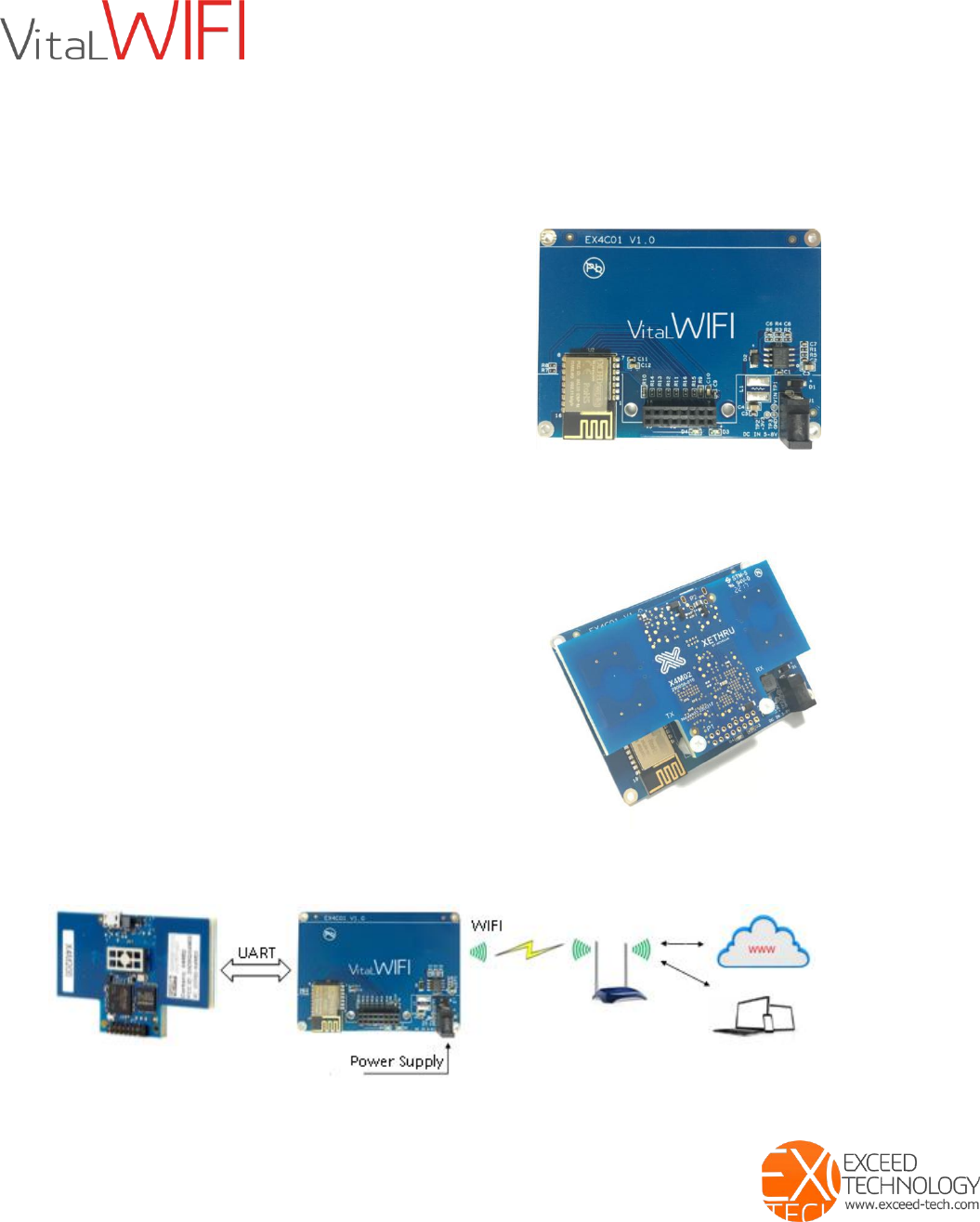
VitalWIFI (EX4C01) is designed to bundle with the X4M200, X4M300 sensors. VitalWiFi equips
the XeThru sensor modules with standalone power supply and WIFI communication capabilities.
The X4M200 and X4M300 can now stream outputs independently and directly to data servers
and cloud applications.
Features
Plug and Go XeThru UWB radar sensor system
No extra hardware needed
Standalone power system
Provides WIFI communication and control;
Provides power to X4M200 and X4M300;
Physical interface to mount and secure the sensor
Compact size
Multiple encapsulation options
Compatible with XeThru X4M200 & X4M300
Applications
WiFi ready Respiration Sensor
oEX4C01 + X4M200
WiFi ready Presence Sensor
oEX4C01 + X4M300
VitalWIFI bridges the X4M200/X4M300 modules to an existing WiFi network. With VitalWIFI,
user can easily manage and control the device networking requirement.
When VitalWiFi is working as a TCP Client, it will initiate request for 2-way
EX4C01 works with X4M200, X4M300
PN: 900117121
X4M200/X4M300
module
WiFi Ready – Plug & Go
Exceed Technology Co. Limited
www.exceed-tech.com
E: ask@exceed-tech.com, Tel: + 852 9738 7071, Whatsapp: +85297387071
connections with a TCP Server device. Upon successful connection, transparent transmission
between Server and Client is enabled. The server end could be a fixed IP from the Internet, or a
device within the network with an intranet IP
Plug and Ready to use
No further hardware development required. Using the Vital-WIFI, the XeThru sensor modules
can now be managed via WIFI. Users only need to focus on developing the backend software
interfaces.
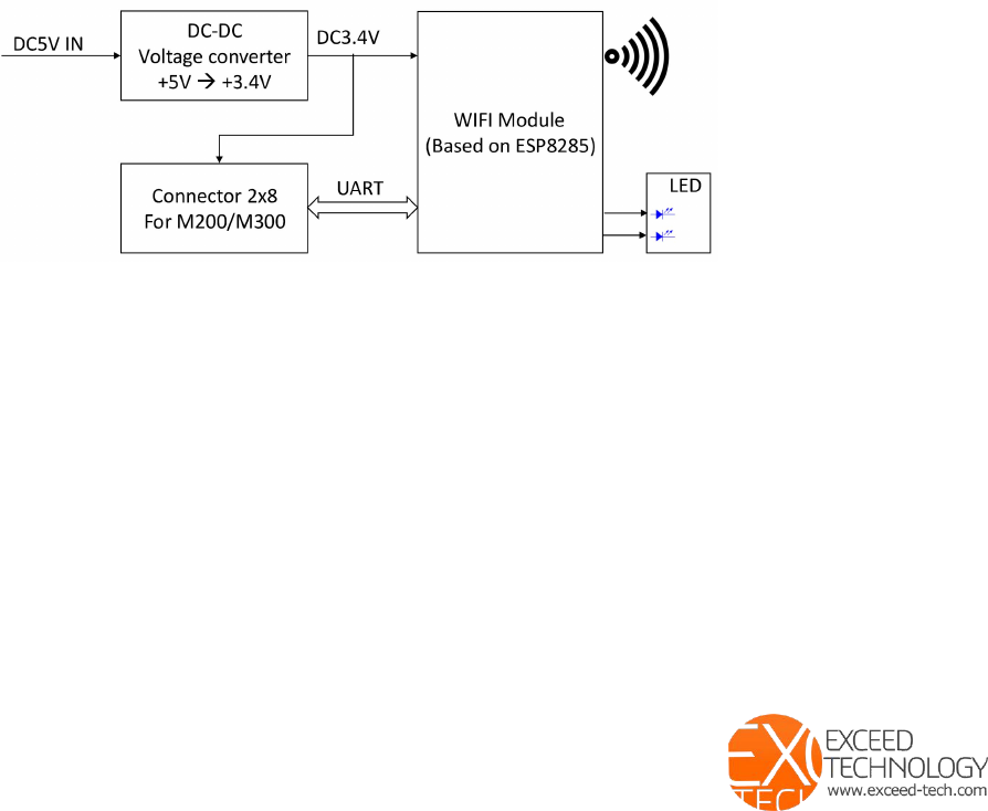
Schematic diagram
VitalWIF(EX4C01) is made up of DC-DC voltage converter, WIFI module,connectors and LED.
DC-DC converter steps down the +5V DC input to +3.4V DC. Maximum current 1.5A.
Connector provides power to X4M200/X4M300, and the UART communication link
WIFI module is based on ESP8285, which can establish transmission to a cloud server.
LED is used to indicate WIFI status. When there is no network connection, the LED flashes in
constant interval. When a connection is established, the LED is stands On. During data
transmission, LED flashes when receiving and transmitting.
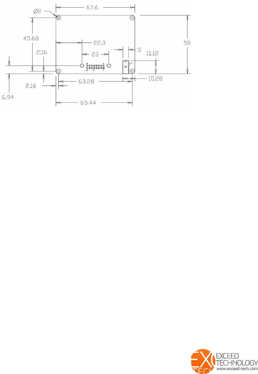
Compact and easy to use
Board dimensions are 50mm x 67.6mm x 21mm, when assembled with the X4M200 or X4M300.
Special design considerations must be given to ensure signal integrity, especially with several RF
antennas on board. Exceed Technology offers the product in standard encapsulation, custom
encapsulations and PCB assembly. Mechanical drawings can be made available to support
encapsulation designs.
Technical Specifications
Compatible with X4M200, X4M300
Frequency range:2.4G~2.5G(2400~2483.5M)
Transmitting power: 802.11b: +20dBm

WiFi Ready – Plug & Go
Exceed Technology Co. Limited
www.exceed-tech.com
E: ask@exceed-tech.com, Tel: + 852 9738 7071, Whatsapp: +85297387071
802.11g: +17dBm
802.11n: +14dBm
receiving sensitivity: 802.11b: -91dBm
802.11g: -75dBm
802.11n: -72dBm
Supports 80211 b/g/n/e/I;
Supports Station、SoftAP、SoftAP+STA mode;
Supports WI-FI Direct(P2P);
Supports WPA/PA2 PSK and WPS;
Seamless Roaming;
Built-in HTTP Web Server, Supporting web configuration parameter;
Supporting TCP Server,TCP Client,UDP Server,UDP Client and UDP Broadcast;
Support AP enable, customize SSID/password, customize IP and network segments;
Automatically scan peripheral hotspots, support STA enabling, DHCP, customize IP and
network segments;
Support for using serial port at command to set and view WIFI status;
Remote Server address support DNS Domain name Auto-resolution;
Antenna:PCB embedded antenna;
UART : Default 115200 baud rate,8 data bits,1 stop bit,no parity. Parameters can be
changed as needed
Dimensions:50mm X 67.6 mm;
Working Temperature :-40° to 125°
Other Specifications
Power supply: 5V DC
Power current: 200mA (including X4M200/X4M300)
PCB size: 50 x 67.6 mm
Assembly size: 50 x 67.6 x 21 mm
WiFi Ready – Plug & Go
Exceed Technology Co. Limited
www.exceed-tech.com
E: ask@exceed-tech.com, Tel: + 852 9738 7071, Whatsapp: +85297387071
Availability and options
Available from January 2018
Standard encapsulation
oColor :White, Black
oDimension: 80 * 80 * 26 mm,
oMaterial: ABS
Custom encapsulation
oCustomized designs
PCB Assembly
oDesign and manufacture your own encapsulation

WiFi Ready – Plug & Go
Exceed Technology Co. Limited
www.exceed-tech.com
E: ask@exceed-tech.com, Tel: + 852 9738 7071, Whatsapp: +85297387071
AT Command Instruction Set:
Data Direction
Instruction(ASCII Character string)
Meaning
Query STA state
MCU WIFI
AT+STASTATUS
Query STA schema status
WIFI MCU
STA:OK
STA connected
WIFI MCU
STA:DOWN
STA disconnected
Get the IP and MAC of the STA mode
MCU WIFI
AT+STAINFO
Get the MAC and IP of WIFI
WIFI MCU
Mac|IP Sample
5CCF7F116380|192.168.1.102
MAC address and IP address
in STA Mode
Query the connection state in the TCP Client mode
MCUWIFI
AT+TCPCLIENT
Query join status in TCP
Client mode, no sense in
other modes
WIFIMCU
TCP:OK
TCP Client connected
WIFIMCU
TCP:OFF
TCP Client disconnected
Reset WIFI
MCU WIFI
AT+RST
Reset WIFI
WIFI MCU
RST:OK
Response
Restoration of factory setting
MCU WIFI
AT+RESTORE
WIFI Restore and reboot
WIFI MCU
RESTORE:OK
Response
Exceed WIFI module access and set up.
1.Please connect DC5V to the board ->System power up -> Green LED on WiFI board + LED on
Xethru module flashing.
2.The module starts searching for WIFI networks. If this is new WiFi network, then User set
up is required. Please note both AP and STATION modes are provided by the WiFi module.
3.Using a PC or mobile phone, search for ( Exceed_Wifi_xxxxxx) and connect to it.
4.Enter 192.168.4.1 to access WiFi set up.
WiFi Ready – Plug & Go
Exceed Technology Co. Limited
www.exceed-tech.com
E: ask@exceed-tech.com, Tel: + 852 9738 7071, Whatsapp: +85297387071
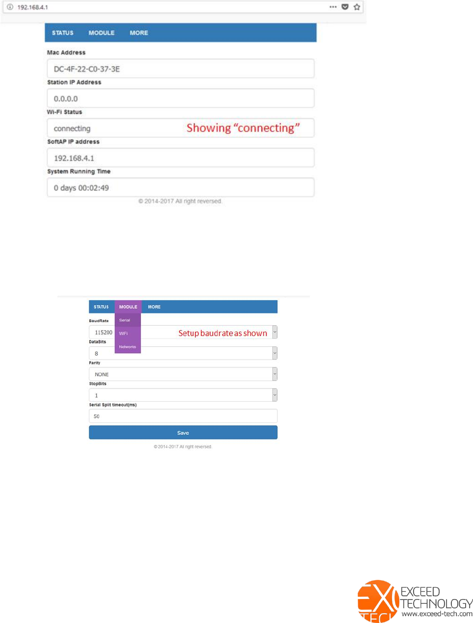
5.Once connected, select STATUS , check that WiFi Status is showing “connecting”.
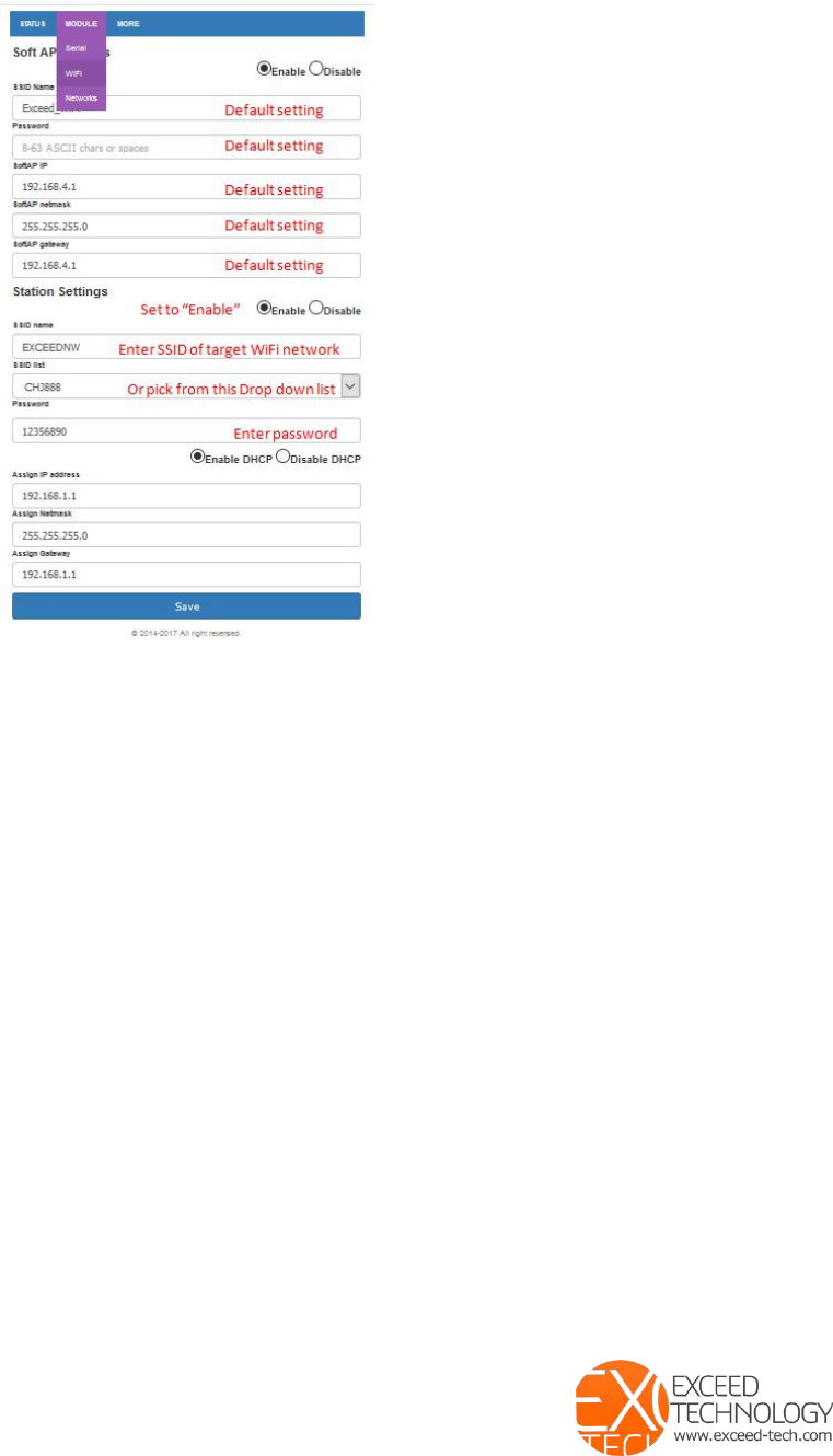
6.Select Module -> Serial
7.Confirm “Baudrate” is 115200
8.Save
9.Select Module -> WiFi
10.Station Settings -> Enabled
11.Enter the SSID name you are connecting to or select from the drop down SSID list
12.Enter Password accordingly
13.Save
WiFi Ready – Plug & Go
Exceed Technology Co. Limited
www.exceed-tech.com
E: ask@exceed-tech.com, Tel: + 852 9738 7071, Whatsapp: +85297387071
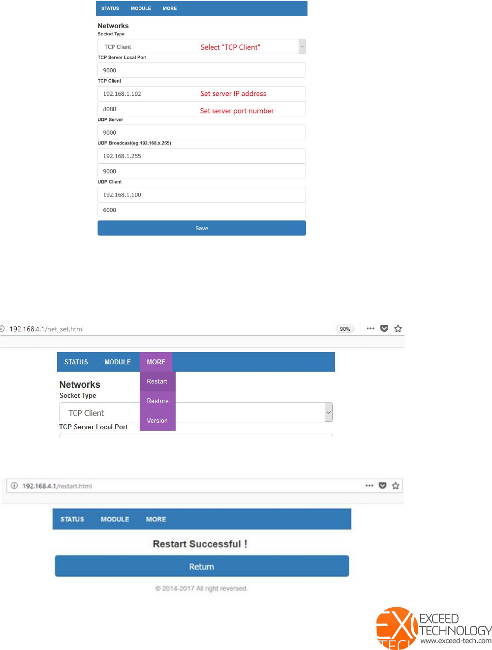
14.Select Module -> Network
15.Socket Type -> TCP Client (VitalWIFI supports TCP Server、TCP Client、UDP Server、
UDP Client andUDP BroadCast. Depending on the network requirement, user may select any
of the supported Socket Type and respective settings.),
The following example uses TCP Client,ie: Socket Type ->TCP Client)
16.TCP Client -> set the respective IP address and local port of the server
17.Save
WiFi Ready – Plug & Go
Exceed Technology Co. Limited
www.exceed-tech.com
E: ask@exceed-tech.com, Tel: + 852 9738 7071, Whatsapp: +85297387071
18.Select More -> Restart - this will start the module with the new settings.
19.Check for Restart Successful
WiFi Ready – Plug & Go
Exceed Technology Co. Limited
www.exceed-tech.com
E: ask@exceed-tech.com, Tel: + 852 9738 7071, Whatsapp: +85297387071
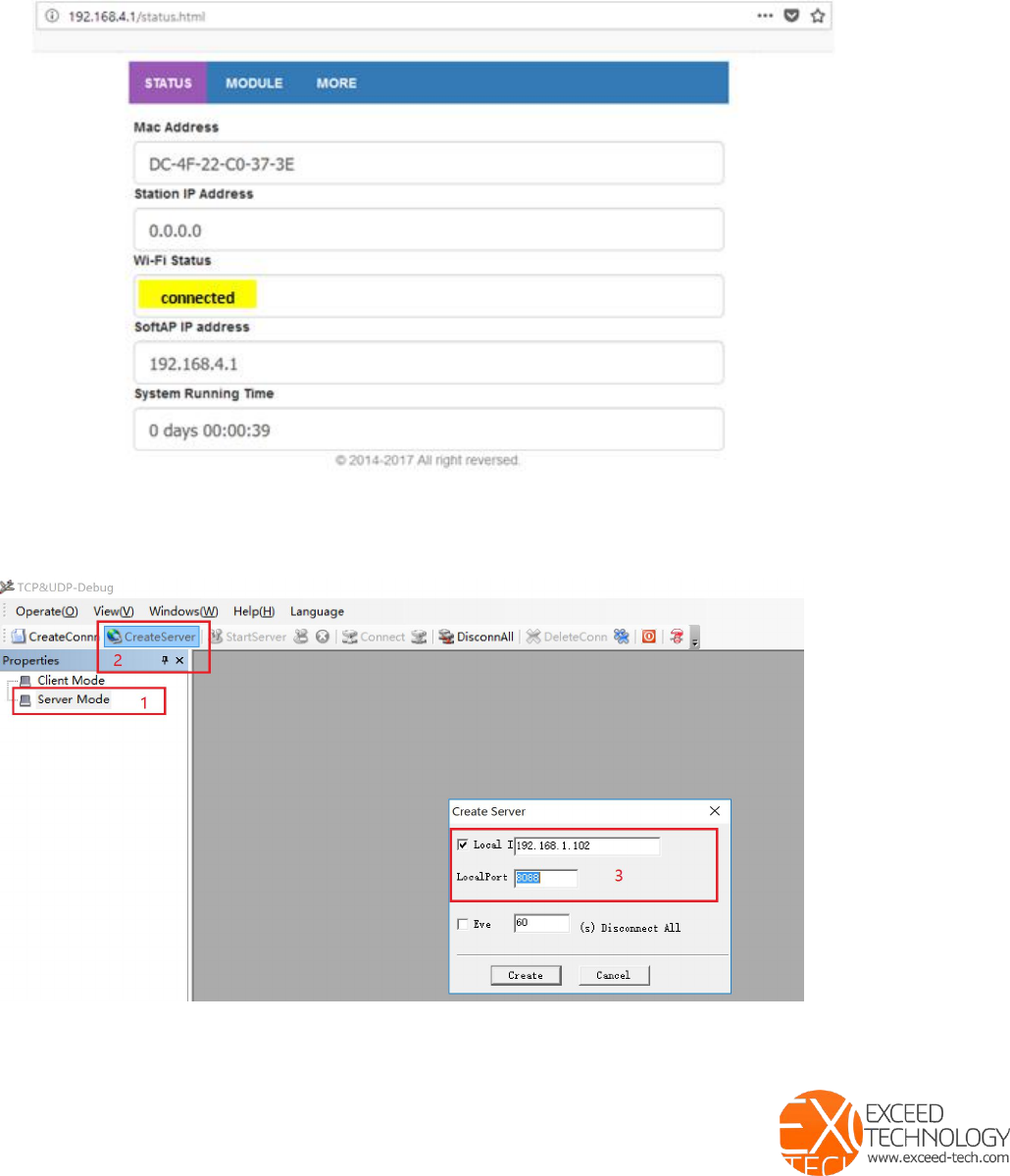
20.Select STATUS , check that WiFi Status is showing “connected”.
21.Set Up Completed
22.Activate TCPUDPbg ( testing program) , select Server Mode and CreateServer. Set the
Local IP address and LocalPort. Please note the settings here must be identical to those
settings in step 18. Create TCP server.
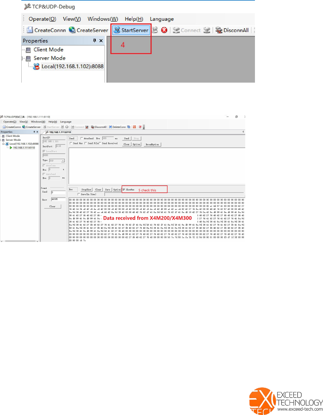
23.Click - StartServer,establish TCP connection.
WiFi Ready – Plug & Go
Exceed Technology Co. Limited
www.exceed-tech.com
E: ask@exceed-tech.com, Tel: + 852 9738 7071, Whatsapp: +85297387071
24.Click on ShowHex, to display the data in hex format. The content in the receiving
window is the data received directly from the UART of X4M200.X4M300. ie transparent
data transmission from VitalSCAN (TCP client) to TCP Serder.

WiFi Ready – Plug & Go
Exceed Technology Co. Limited
www.exceed-tech.com
E: ask@exceed-tech.com, Tel: + 852 9738 7071, Whatsapp: +85297387071
ATTENTION
This device complies with part 15 of the FCC Rules. Operation is subject to the condition that
this device does not cause harmful interference (1) this device may not cause harmful
interference, and (2) this device must accept any interference received, including interference
that may cause undesired operation.
Changes or modifications not expressly approved by the party responsible for compliance could
void the user's authority to operate the equipment.
NOTE: This equipment has been tested and found to comply with the limits for a Class B digital
device, pursuant to Part 15 of the FCC Rules. These limits are designed to provide reasonable
protection against harmful interference in a residential installation. This equipment generates,
uses and can radiate radio frequency energy and, if not installed and used in accordance with the
instructions, may cause harmful interference to radio communications. However, there is no
guarantee that interference will not occur in a particular installation.
If this equipment does cause harmful interference to radio or television reception, which can be
determined by turning the equipment off and on, the user is encouraged to try to correct the
interference by one or more of the following measures:
- Reorient or relocate the receiving antenna.
- Increase the separation between the equipment and receiver.
- Connect the equipment into an outlet on a circuit different from that to which the receiver is
connected.
- Consult the dealer or an experienced radio/TV technician for help.
To maintain compliance with FCC’s RF Exposure guidelines, this equipment should be installed
and operated with minimum distance between 20cm the radiator your body: Use only the
supplied antenna.
FCC ID:2APQO-EX4C01