Excera Technology ER9000U1 Digital Repeater User Manual FCC IC 0721
Shenzhen Excera Technology Co., Ltd. Digital Repeater FCC IC 0721
UserManual.wiki
>
Excera Technology
>
ER9000U1 User Manual
User Manual-FCC&IC-0721
Navigation menu
Upload a User Manual
Namespaces
Wiki Guide
HTML
PDF
Info
Views
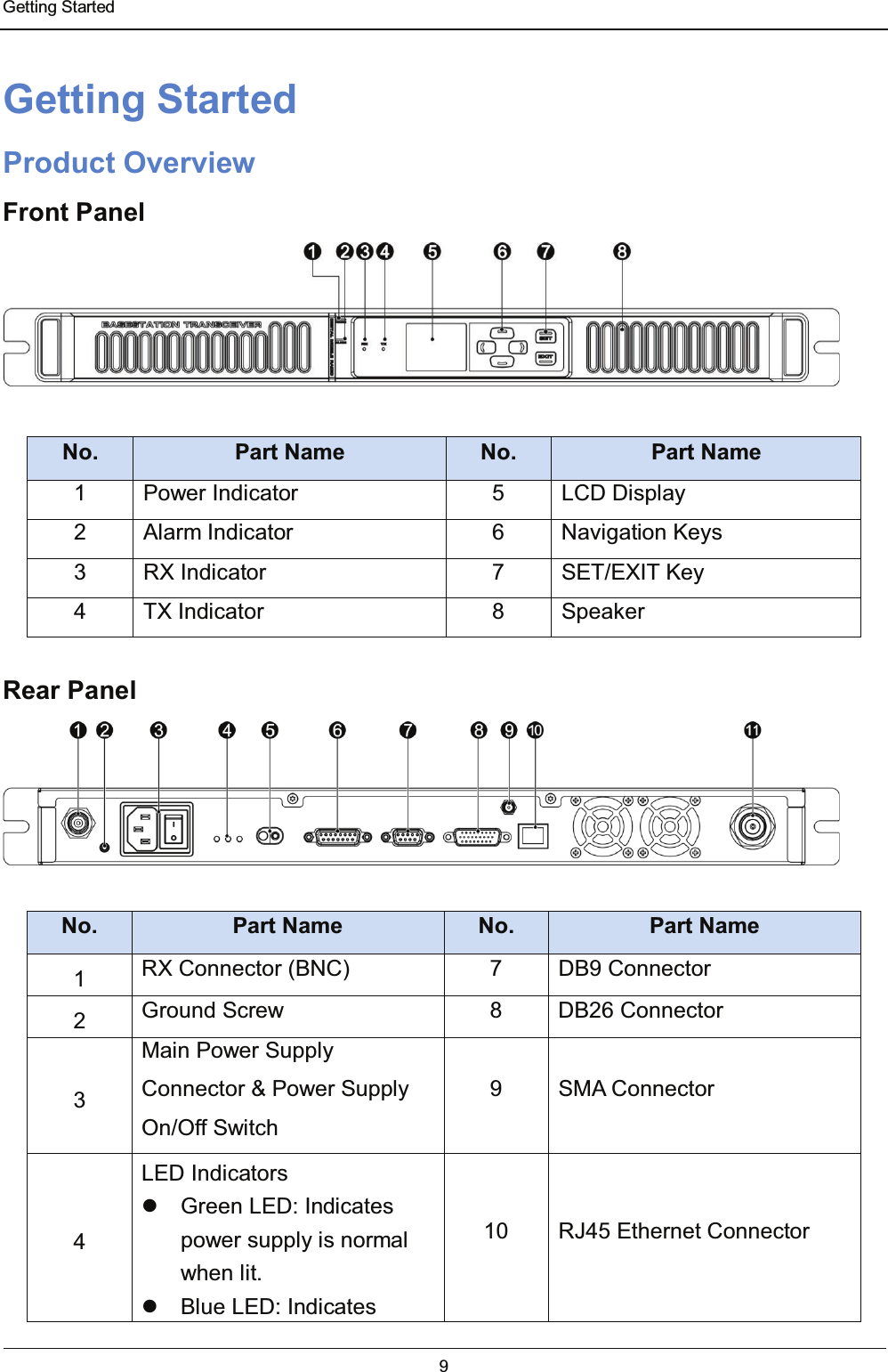
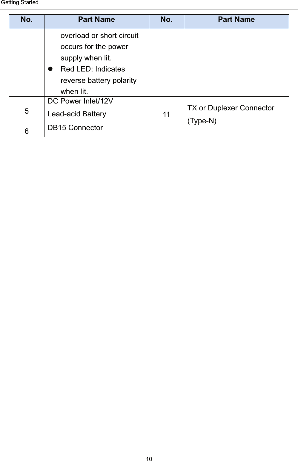
User Manual
Discussion / Help
Navigation
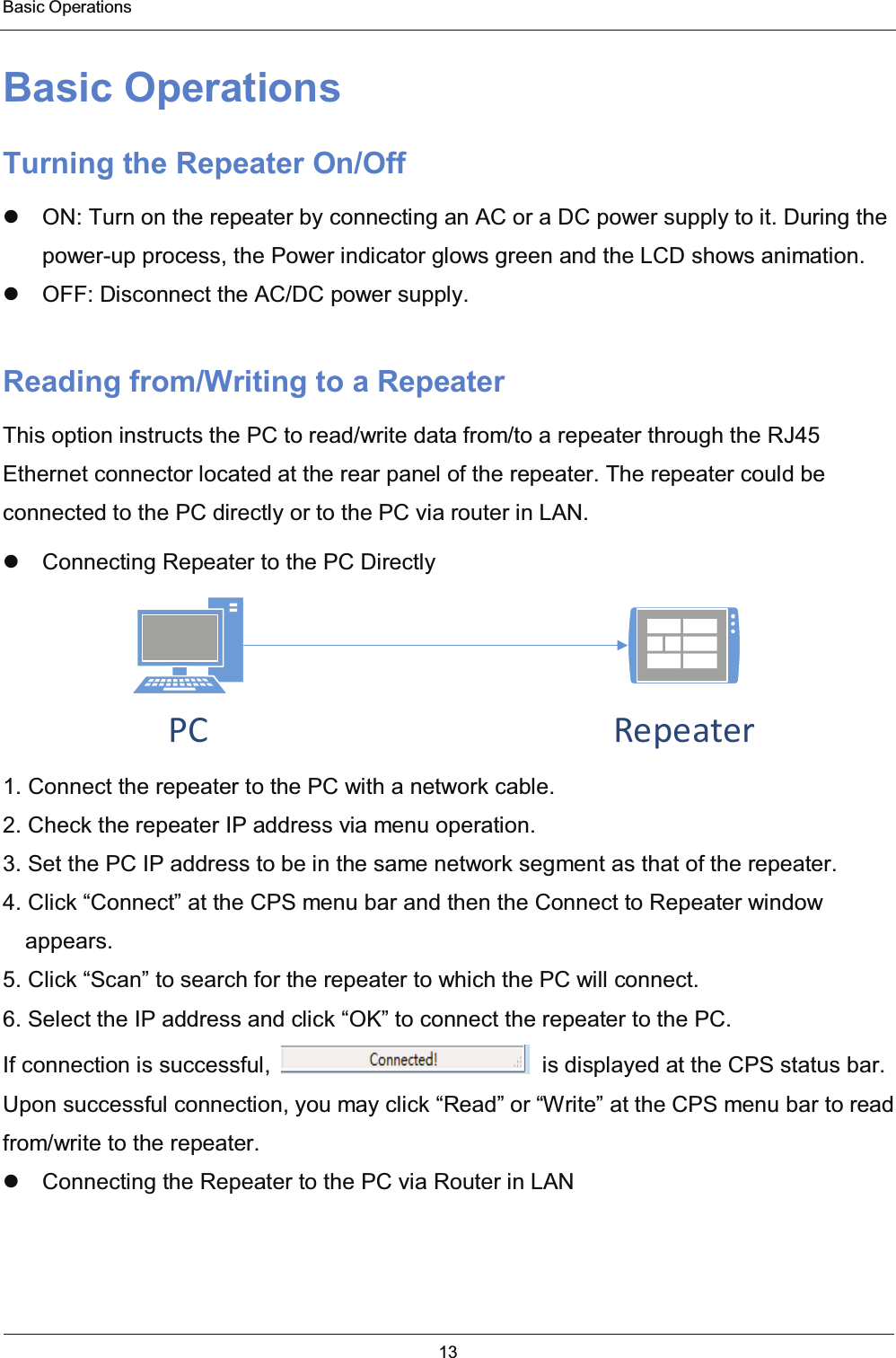
![Disclaimer 35 Disclaimer The information in this manual is carefully examined and is believed to be entirely reliable. However, no responsibility is assumed for inaccuracies. All the specifications and designs are subject to change without notice due to continuous technology development. No part of this manual may be copied, modified, translated, or distributed in any manner without the prior written permission of the Company.5)+LJK3RZHU:5)/RZ3RZHU:7KHPD[LPXPDOORZDEOHVWDWLRQHIIHFWLYHUDGLDWHGSRZHU(53LVGHSHQGHQWXSRQWKHVWDWLRQVDQWHQQD+$$7DQGUHTXLUHGVHUYLFHDUHDDQGZLOOEHDXWKRUL]HGLQDFFRUGDQFHZLWKWDEOH](https://usermanual.wiki/Excera-Technology/ER9000U1/User-Guide-3076315-Page-38.png)