Excera Technology ER9000U1 Digital Repeater User Manual FCC IC 0721
Shenzhen Excera Technology Co., Ltd. Digital Repeater FCC IC 0721
User Manual-FCC&IC-0721

Contents
i
Contents
Important Information ................................................................................................... 1
RF Energy Exposure Information .......................................................................... 2
Operation Safety Recommendations .................................................................... 4
Alert Icon ............................................................................................................... 7
Disabled Frequencies ........................................................................................... 7
Checking Items in the Package .................................................................................... 8
Getting Started ............................................................................................................. 9
Product Overview ................................................................................................. 9
Installation Guide ................................................................................................ 11
Installation Requirements ............................................................................ 11
Installation Steps ......................................................................................... 11
LCD Icon ............................................................................................................. 12
LED Indicator ...................................................................................................... 12
Basic Operations ........................................................................................................ 13
Turning the Repeater On/Off .............................................................................. 13
Reading from/Writing to a Repeater.................................................................... 13
Adjusting the Volume .......................................................................................... 14
Squelch Level ..................................................................................................... 14
Scan.................................................................................................................... 16
Power Level ........................................................................................................ 17
Zone.................................................................................................................... 17
Backlight ............................................................................................................. 18
Brightness ........................................................................................................... 19
Menu Reset ........................................................................................................ 19
TX/RX LED ......................................................................................................... 20

Contents
ii
Language ............................................................................................................ 21
Locking/Unlocking the Repeater ......................................................................... 21
Menu Navigation ........................................................................................................ 22
Repeater Information .......................................................................................... 22
Channel Information............................................................................................ 22
Device Information .............................................................................................. 23
IP Information .............................................................................................. 23
IP Information Reset .................................................................................... 24
Alarm Information ....................................................................................................... 25
POST Error Alarm ............................................................................................... 25
Over Temperature Alarm .................................................................................... 26
Fan Failure Alarm ............................................................................................... 27
VSWR Alarm ....................................................................................................... 27
Low Forward Power Alarm .................................................................................. 28
Over/Low Voltage Alarm ..................................................................................... 29
TX/RX Unlock Alarm ........................................................................................... 30
Optional Accessories ................................................................................................. 31
Troubleshooting ......................................................................................................... 32
Care and Cleaning ..................................................................................................... 33
Product Care ....................................................................................................... 33
Product Cleaning ................................................................................................ 33
Limited Warranty ........................................................................................................ 34
Disclaimer .................................................................................................................. 35
Warranty Card ............................................................................................................ 36

Important Information
1
Important Information
Note: Ic Note : Cet Appareil Est Conforme À La Partie 15 Des Règlements De La Fcc Et
Aux Normes Rss De L’industrie Du Canada. Son Fonctionnement Est Soumis Aux Deux
Conditions Suivantes : (1) Cet Appareil Ne Doit Pas Causer Des Interférences Nuisibles,
Et (2) Cet Appareil Doit Accepter Toute Interférence Reçue, Y Compris Les Interférences
Qui Peuvent Provoquer Un Fonctionnement Indésirable..
Le Fabricant N'est Pas Responsable Des Toutes Interférences Radio Ou Télévision
Causées Par Des Modifications Non Autorisées Apportées À Cet Appareil. De Telles
Modifications Peuvent Empêcher L’utilisateur D’utiliser L'appareil.
Ic Note:
This Device Complies With Part 15 Of The Fcc Rules And Industry Canada
License-exempt Rss Standard(s). Operation Is Subject To The Following Two Conditions:
(1) This Device May Not Cause Harmful Interference, And (2) This Device Must Accept
Any Interference Received, Including Interference That May Cause Undesired Operation.
The Manufacturer Is Not Responsible For Any Radio Or Tv Interference Caused By
Unauthorized Modifications Or Change To This Equipment. Such Modifications Or
Change Could Void The User’s Authority To Operate The Equipment.
The Users Manual Or Instruction Manual For An Intentional Or Unintentional Radiator
Shall Caution The User That Changes Or Modifications Not Expressly Approved By The
Party Responsible For Compliance Could Void The User's Authority To Operate The
Equipment. In Cases Where The Manual Is Provided Only In A Form Other Than Paper,
Such As On A Computer Disk Or Over The Internet, The Information Required By This
Section May Be Included In The Manual In That Alternative Form, Provided The User Can
Reasonably Be Expected To Have The Capability To Access Information In That Form.
Before using this product, please read this user manual carefully.
Important Information
2
RF Energy Exposure Information
RF Energy Exposure Awareness And Control
Information For Fcc Occupational Use Requirements
Ibefore using the two-way portable radio, review the following important RF energy
awareness and control information and operational instructions. Comply with this
information and instructions in order to ensure compliance with RF exposure guidelines.e
the capability to access information in that form.
This radio is intended for use in occupational/controlled conditions, where
users have full knowledge of their exposure and can exercise control over
their exposure to remain below RF exposure limits. This radio is NOT
authorized for general population, consumer, or any other use.
Changes or modifications not expressly approved by Shenzhen Excera
Technology Co., Ltd.could void the user's authority to operate the
equipment.
This two-way radio uses electromagnetic energy in the radio frequency (RF) spectrum to
provide communications between two or more users over a distance. It uses RF energy or
radio waves to send and receive calls. RF energy is one form of electromagnetic energy.
Other forms include, but are not limited to, electric power, sunlight, and x-rays. RF energy,
however, should not be confused with these other
forms of electromagnetic energy, which, when used improperly, can cause biological
damage. Very high levels of x-rays, for example, can damage tissues and genetic
material.
Experts in science, engineering, medicine, health, and industry work with organizations to
develop standards for exposure to RF energy. These standards provide recommended
levels of RF exposure for both workers and the general public. These recommended RF
exposure levels include substantial margins of protection. All two-way radios marketed in
North America are designed, manufactured, and tested to ensure they meet

Important Information
3
government-established RF exposure levels. In addition, manufacturers also recommend
specific operating instructions to users of two-way radios. These instructions are important
because they inform users about RF energy exposure and provide simple procedures on
how to control it. Refer to the following websites for more information on what RF energy
exposure is and how to control exposure to assure compliance with established RF
exposure limits:
http://www.fcc.gov/oet/rfsafety/rf-faqs.html
http://www.osha.gov./SLTC/radiofrequencyradiation/index.html

Important Information
4
Federal Communications Commission Regulations
Before it was marketed in the United States, the Digital portable radio was tested to
ensure compliance with FCC RF energy exposure limits for two-way portable radios.
When two-way radios are used as a consequence of employment, the FCC requires users
to be fully aware of and able to control their exposure to meet occupational requirements.
Exposure awareness can be facilitated by the use of a
label directing users to specific user awareness information. The radio has an RF
exposure product label.
Also, the Product Safety Manual and this Operator’s Manual include information and
operating instructions required to control RF exposure and to satisfy compliance
requirements.
Operation Safety Recommendations
Occupational Safety Guidelines And Safety Training Information
To ensure bodily exposure to RF electromagnetic energy is within the FCC allowable limits
for occupational use. Always adhere to the following basic guidelines:
The push-to-talk button should only be depressed when intending to send a voice
message.
The radio should only be used for necessary work-related communications.
The radio should only be used by authorized and trained personnel. It should never be
operated by children.
Do not attempt any unauthorized modification to the radio. Changes or modifications
to the radio may cause harmful interference and/or cause it to exceed FCC RF
exposure limits. Only qualified personnel should service the radio.
Always use only authorized accessories (antennas, control heads, speakers/mics,
etc.). Use of unauthorized accessories can cause the FCC RF exposure compliance
requirements to be exceeded.
The information listed above provides the user with information needed to make him or her
aware of a RF exposure, and what to do to assure that this radio operates within the FCC
exposure limits of this radio.

Important Information
5
Radio Frequency Interference
FCC Part 15
This device complies with Part 15 of the FCC Rules. Operation is subject to the following
two conditions:
1. This device may not cause harmful interference; and,
2. This device must accept any interference received, including interference that may
cause undesired operation.
Industry Canada
This device complies with Industry Canada license-exempt RSS standard(s). Operation is
subject to the following two conditions: (1) this device may
not cause interference, and (2) this device must accept any interference, including
interference that may cause undesired operation of the device.
Le présent appareil est conforme aux CNR d'Industrie Canada applicables aux appareils
radio exempts de licence. L'exploitation est autorisée aux
deux conditions suivantes : (1) l'appareil ne doit pas produire de brouillage, et (2)
l'utilisateur de l'appareil doit accepter tout brouillage radioélectrique
subi, même si le brouillage est susceptible d'en compromettre le fonctionnement.
CAUTION:
RISK OF EXPLOSION IF BATTERY IS REPLACED BY AN INCORRECT TYPE.
DISPOSE OF USED BATTERIES
ACCORDING TO THE INSTRUCTIONS.
Adapter shall be installed near the equipment and shall be easily accessible.
The max operating of the device is 60đ.
7RHQVXUHRSWLPDOSHUIRUPDQFHDQGFRPSOLDQFHZLWKWKHRFFXSDWLRQDOFRQWUROOHGHQYLURQPHQW
5)HQHUJ\H[SRVXUHOLPLWVLQWKHDERYHVWDQGDUGVDQGJXLGHOLQHVXVHUVVKRXOGWUDQVPLWQRW
PRUHWKDQRIWKHWLPHDQGDOZD\VDGKHUHWRWKHIROORZLQJSURFHGXUHV<RXUUDGLRUDGLDWHV
PHDVXUDEOH5)HQHUJ\RQO\ZKLOHLWLVWUDQVPLWWLQJGXULQJWDONLQJQRWZKHQLWLVUHFHLYLQJOLVWHQLQJ
RULQVWDQGE\PRGH$QWHQQDJDLQPXVWQRWH[FHHGG%L7KHDQWHQQDLQVWDOODWLRQFRPSO\ZLWK
WKHUHTXLUHPHQWVRIPDQXIDFWXUHURUVXSSOLHUDQGDWOHDVW3.8PIURPDQ\ERG\SDUWRIWKHXVHURU
QHDUE\SHUVRQV

Important Information
6
EU Regulatory Conformance
As certified by the qualified laboratory, the product is in compliance with the essential
requirements and other relevant provisions of the Directive 199/5/EC.Please note that
the above information is applicable to EU countries only.
Important Information
7
Alert Icon
Caution: Indicates situations that could cause human injury or damage to your
products.
Note: Indicates tips that can help you make better use of your products.
Disabled Frequencies
400
–
470 MHz
No. Frequency
1 408 MHz
2 417.6 MHz
3 427.2 MHz
4 436.8 MHz
5 446.4 MHz
6 456 MHz
7 465.6 MHz
Caution!
This radio is restricted to occupational use only to satisfy FCC RF energy exposure
requirements.
Checking Items in the Package
8
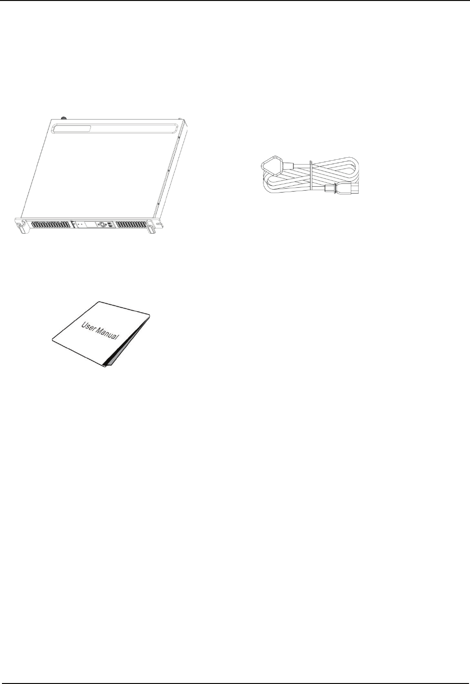
Checking Items in the Package
Please unpack carefully and check that all items listed below are received. If any item is
missing or damaged, please contact your dealer.
❶ Repeater ❷ Power Cord
❸ User Manual
Getting Started
9
Getting Started
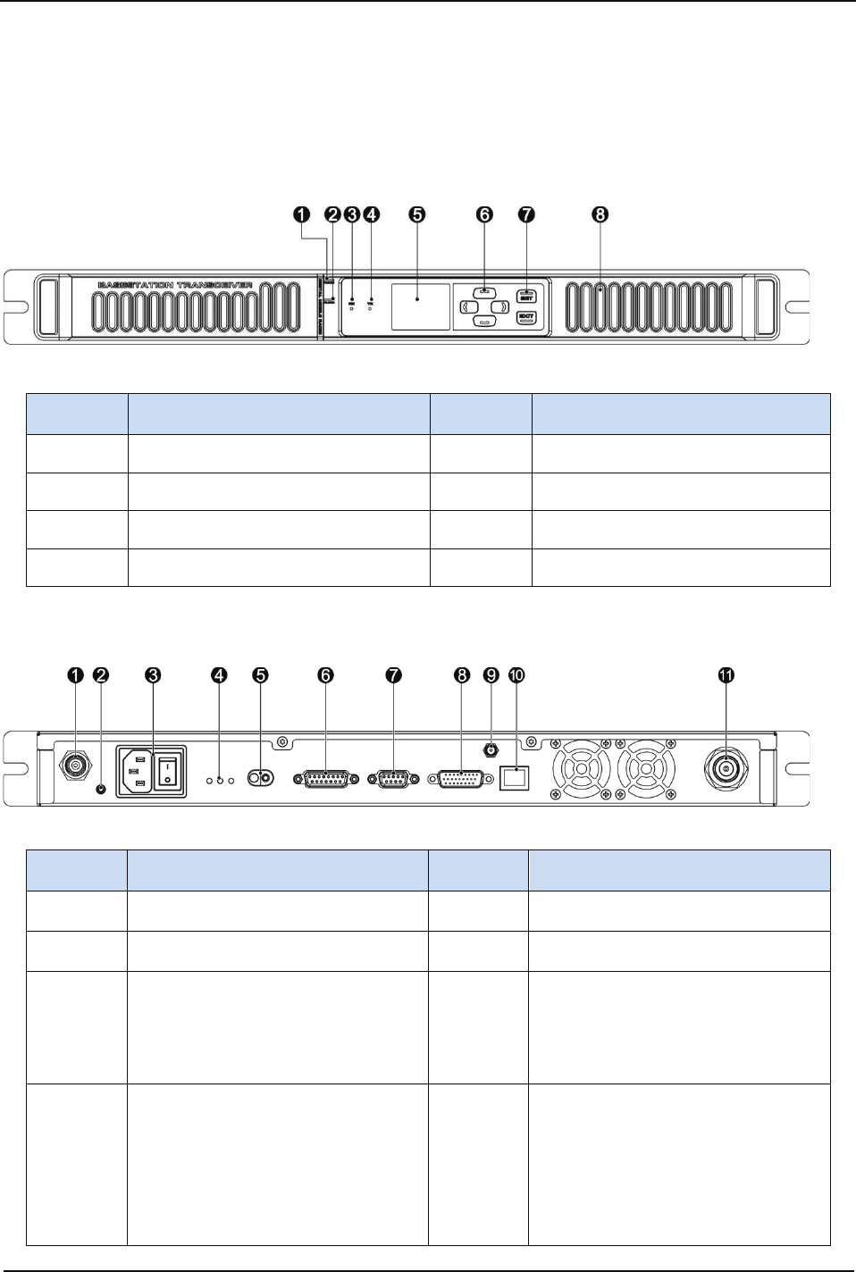
Product Overview
Front Panel
No. Part Name No. Part Name
1 Power Indicator 5 LCD Display
2 Alarm Indicator 6 Navigation Keys
3 RX Indicator 7 SET/EXIT Key
4 TX Indicator 8 Speaker
Rear Panel
No. Part Name No. Part Name
1 RX Connector (BNC) 7 DB9 Connector
2 Ground Screw 8 DB26 Connector
3
Main Power Supply
Connector & Power Supply
On/Off Switch
9 SMA Connector
4
LED Indicators
Green LED: Indicates
power supply is normal
when lit.
Blue LED: Indicates
10 RJ45 Ethernet Connector

Getting Started
10
No. Part Name No. Part Name
overload or short circuit
occurs for the power
supply when lit.
Red LED: Indicates
reverse battery polarity
when lit.
5
DC Power Inlet/12V
Lead-acid Battery 11 TX or Duplexer Connector
(Type-N)
6 DB15 Connector
Getting Started
11
Installation Guide
Proper installation ensures the best possible performance and reliability of the repeater.
Therefore, be sure to read the following instructions before installation.
Installation Requirements
1. Installation Environment
The repeater must be installed in a dry and well-ventilated place with ambient temperature
of -30°C to +60°C and relative humidity of no more than 95%.
2. Installation Location
The repeater can be installed on a rack, bracket, and cabinet, or on a desk.
Caution: DO NOT place heavy objects on the repeater chassis.
Installation Steps
Install the repeater as follows:
1. Install the repeater at a proper location.
2. Attach all necessary accessories, like antenna feeder, power cord, data cable, etc.
3. Ground the repeater through the ground screw located on the rear panel.
Note:
If the DC power supply or 12V lead-acid battery is used to supply power to the
repeater, check and ensure that V
DC or battery voltage is within the repeater operating
voltage range of 10.8V to 16.5V.
Check and make sure no blocking occurs for the air inlet on the front panel and the
cooling fan on the rear panel.
After turning on the repeater, check whether the repeater works properly by observing
the states of the Power and Alarm Indicators and located on the front panel.
Parameter Configuration
When the repeater proves to work normally, configure appropriate parameters (e.g.
operating frequency, TX power, and signalling type) as per your actual requirements.
Caution: Disconnect the power supply to the repeater before opening the chassis.
Getting Started
12
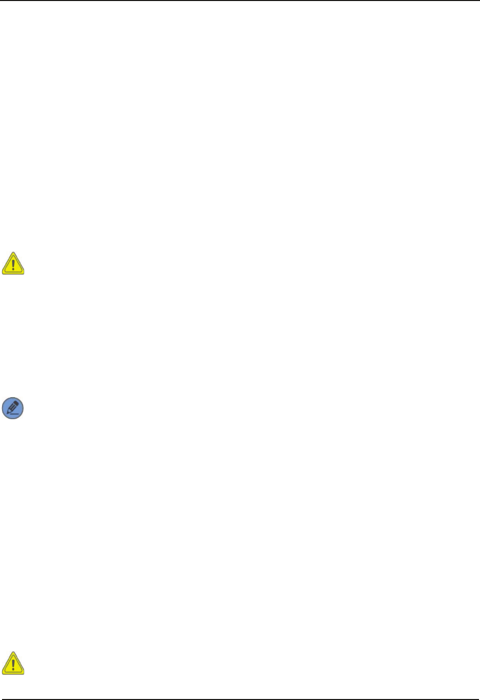
LCD Icon
Icon Name Icon Repeater Status
Scan Indicator Scan is in progress when lit.
TX Power Indicator
Low TX power for the current
channel
High TX power for the current
channel
Network Connection
Indicator Network connection is normal when
lit.
Slot Indicator
Repeater is transmitting or receiving
on slot 1 when lit.
Repeater is transmitting or receiving
on slot 2 when lit.
Channel Mode
Indicator
The current channel is an analog or
a digital channel.
LED Indicator
LED Indicator Repeater Status
Power Indicator Repeater is connected to the power supply.
TX Indicator The repeater is transmitting on a digital or an analog
channel.
RX Indicator The repeater is receiving on a digital/an analog channel.
Alarm Indicator The repeater works abnormally.
Basic Operations
13
Basic Operations
Turning the Repeater On/Off
ON: Turn on the repeater by connecting an AC or a DC power supply to it. During the
power-up process, the Power indicator glows green and the LCD shows animation.
OFF: Disconnect the AC/DC power supply.
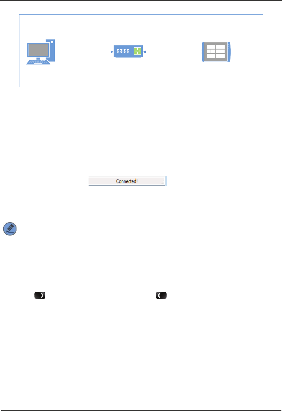
Reading from/Writing to a Repeater
This option instructs the PC to read/write data from/to a repeater through the RJ45
Ethernet connector located at the rear panel of the repeater. The repeater could be
connected to the PC directly or to the PC via router in LAN.
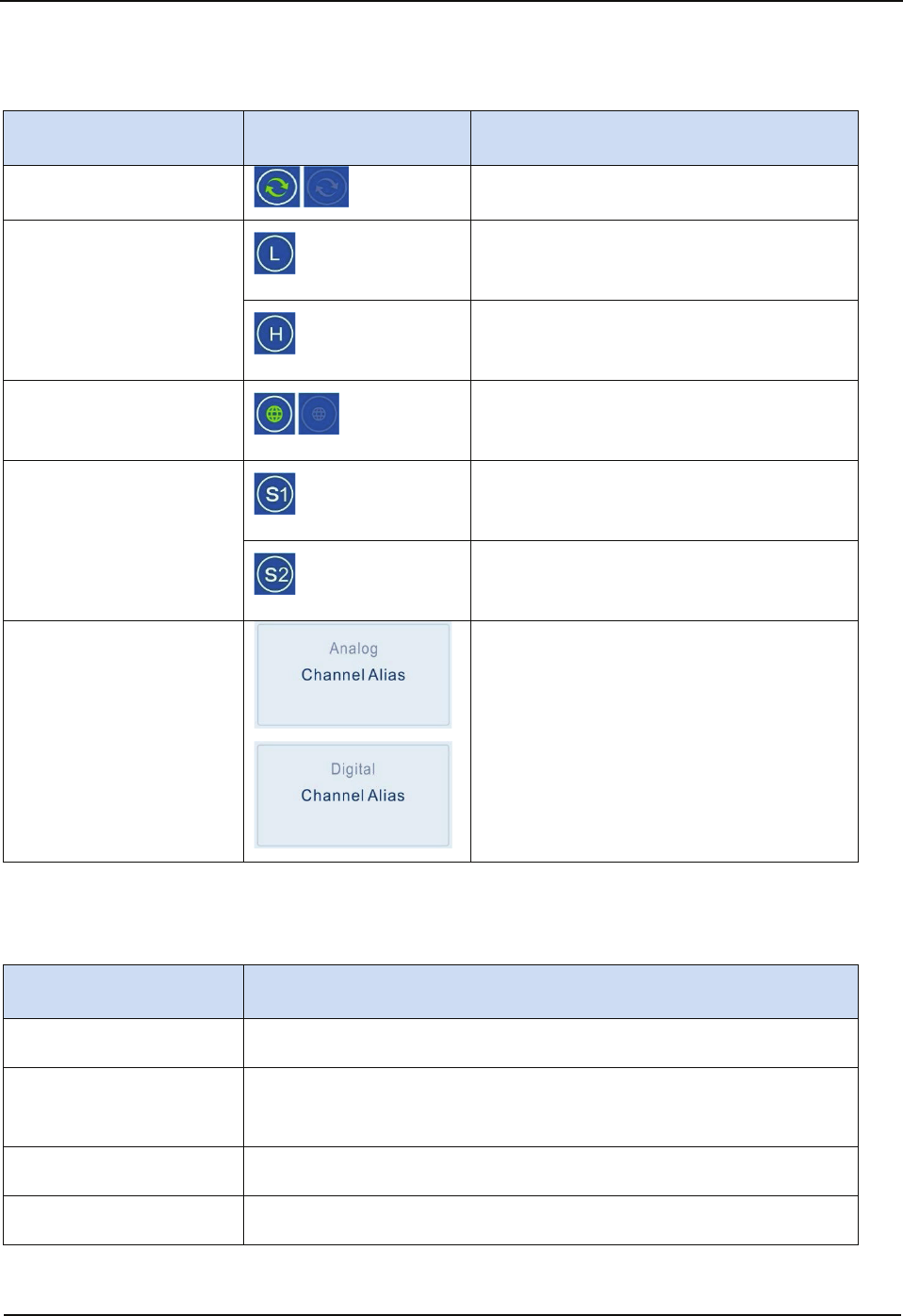
Connecting Repeater to the PC Directly
PC Repeater
1. Connect the repeater to the PC with a network cable.
2. Check the repeater IP address via menu operation.
3. Set the PC IP address to be in the same network segment as that of the repeater.
4. Click “Connect” at the CPS menu bar and then the Connect to Repeater window
appears.
5. Click “Scan” to search for the repeater to which the PC will connect.
6. Select the IP address and click “OK” to connect the repeater to the PC.
If connection is successful, is displayed at the CPS status bar.
Upon successful connection, you may click “Read” or “Write” at the CPS menu bar to read
from/write to the repeater.
Connecting the Repeater to the PC via Router in LAN
Basic Operations
14
RouterPC Repeater
LAN
1. Connect the repeater to the PC via the router in LAN using a network cable.
2. Check the repeater IP address via menu operation.
3. Set the PC IP address to be in the same network segment as that of the repeater.
4. Click “Connect” at the repeater CPS menu bar and then the Connect to Repeater
window appears.
5. Click “Scan” to search for the repeater to which the PC will connect.
6. Select the IP address and click “OK” to connect the repeater to the PC.
If connection is successful, is displayed at the CPS status bar.
Upon successful connection, you may click “Read” or “Write” at the CPS menu bar to read
from/write to the repeater.
Note: Before writing to the repeater, you may revert the PC IP address to its
previous one and set the repeater IP address to be in the same network segment
as that of the PC, to facilitate normal PC operation.
Adjusting the Volume
Press the key to increase the volume or the key to decrease the volume.
Squelch Level
This option can reduce background noise by adjusting the squelch level when the repeater
is receiving signals. You may set the squelch level to Tight, Normal, or Open using the
repeater menu. Tight squelch level can filter weak signals, and allow only strong signals to
be received. If the squelch level is set to Open, the repeater will turn on the speaker and
background noise will be heard.
Follow the procedures below to set the squelch level.

Basic Operations
15
Procedure:
1. In the home screen, press the SET key to enter the main menu.
2. Use the / key to select the “Function” option.
3. Press the SET key to enter the Function menu.
4. Use the / key to select the “Squelch Level” option.
5. Press the SET key to enter the Squelch Level menu.
6. Use the / key to select Open, Normal, or Tight.
7. Press the SET key to set the selected option as the squelch level.
To exit this menu, press the EXIT key.
Note: This feature is applicable to analog channels only.

Basic Operations
16
Scan
The Scan feature allows the repeater to search the scan list that is attached to the current
channel for an eligible channel to receive or unmute.
Before initiating the scan function using the repeater menu, follow the procedures below to
attach a scan list to the current channel using the CPS.
Procedure:
1. Log in to the CPS.
2. Go to “Conventional -> Scan -> Selected Scan List”.
3. Add channels (analog or digital) to be scanned into the Selected Scan List.
4. Go to “Conventional -> Channel -> Digital/Analog Channel -> Current Channel”.
5. In the Scan/Roam List option, attach the Selected Scan List to this channel.
After you have attached a scan list to the current channel, follow the following procedures
to enable/disable the scan feature via menu operation.
Procedure:
1. In the home screen, press the SET key to enter the main menu.
2. Use the / key to select the “Function” option.
3. Press the SET key to enter the Function menu.
4. Use the / key to select the “Scan” option.
5. Press the SET key to enter the Scan menu.
6. Use the / key to select On or Off.
7. Press the SET key to save the settings in the system.
To exit this menu, press the EXIT key.

Basic Operations
17
Power Level
You may set the TX power to High or Low. High power can extend repeater coverage,
enabling you to communicate with farther terminals. The TX power is represented by the
icons and respectively on the LCD display.
Follow the following procedures to set the TX power.
Procedure:
1. In the home screen, press the SET key to enter the main menu.
2. Use the / key to select the “Power Level” option.
3. Press the SET key to enter the Power Level menu.
4. Use the / key to select High or Low.
5. Press the SET key to save the settings in the system.
To exit this menu, press the EXIT key.
Zone
A zone is a group of channels. Your repeater supports up to 128 channels and eight zones
(Zone 0 to Zone 7), with a maximum of 16 channels per zone.
Follow the following procedures to select a zone.
Procedure:
1. In the home screen, press the SET key to enter the main menu.
2. Use the / key to select the “Zone” option.
3. Press the SET key to enter the Zone menu.
4. Use the / key to select a zone.
5. Press the SET key to save the settings in the system.
To exit this menu, press the EXIT key.

Basic Operations
18
Backlight
This option allows users to control the backlight using the menu. Activating the backlight
can illuminate the LCD display, so as to facilitate your operation.
You may set the backlight to operate in any of the following modes:
Timed: Any key press operation can activate the backlight. If no foregoing event
occurs with the specified time period, the backlight will go out automatically.
Never: The backlight remains activated all the time.
Note: When an alarm event occurs, the backlight will remain activated until the
alarm disappears.
Follow the procedures below to set the backlight.
Procedure:
1. In the home screen, press the SET key to enter the main menu.
2. Use the / key to select the “Repeater Settings” option.
3. Press the SET key to enter the Repeater Settings menu.
4. Use the / key to select the “Display” option.
5. Press the SET key to enter the Display menu.
6. Use the / key to select the “Backlight” option.
7. Press the SET key to enter the Backlight menu.
8. Use the / key to select a desired time or Never.
9. Press the SET key to save the settings in the system.
To exit this menu, press the EXIT key.

Basic Operations
19
Brightness
This option allows users to adjust brightness (0-7) using the menu.
Follow the following procedures to set brightness.
Procedure:
1. In the home screen, press the SET key to enter the main menu.
2. Use the / key to select the “Repeater Settings” option.
3. Press the SET key to enter the Repeater Settings menu.
4. Use the / key to select the “Display” option.
5. Press the SET key to enter the Display menu.
6. Use the / key to select the “Brightness” option.
7. Press the SET key to enter the Brightness menu.
8. Press the key to increase brightness or to decrease brightness.
9. Press the SET key to save the settings in the system.
To exit this menu, press the EXIT key.
Menu Reset
This parameter allows users to define the amount of time that the repeater remains in the
menu mode. The counter will be activated after the repeater enters the menu. In the event
of no key press operation within the preset time period, the repeater will automatically exit
the menu.
You may set the menu reset to operate in any of the following modes:
Timed: If no key press occurs within the specified time period, the repeater will
automatically return to the home screen.
Never: The radio user can manually exit the menu only.
Follow the procedures below to set the menu reset time.
Procedure:
1. In the home screen, press the SET key to enter the main menu.
2. Use the / key to select the “Repeater Settings” option.
3. Press the SET key to enter the Repeater Settings menu.
4. Use the / key to select the “Menu Reset” option.

Basic Operations
20
5. Press the SET key to enter the Menu Reset menu.
6. Use the / key to select Never or a desired menu reset time.
7. Press the SET key to save the settings in the system.
To exit this menu, press the EXIT key.
TX/RX LED
This option decides whether to give any LED alert when the repeater is transmitting and/or
receiving.
You can set the following TX/RX LED related parameters: LED Switch, TX LED, and RX
LED.
LED Switch: If the On option is selected, TX LED and RX LED light when
the
repeater is transmitting and receiving. If the Off option is selected, Neither TX LED nor
RX LED lights when the repeater is transmitting and receiving.
TX LED: If the On option is selected, TX LED lights when the repeater is
transmitting. If the Off option is selected, TX LED does not light when the repeater is
transmitting.
RX LED: If the On option is selected, RX LED lights when the repeater is receiving. If
the Off option is selected, RX LED does not light when the repeater is receiving.
Follow the procedures below to set TX/RX LED related parameters.
Procedure:
1. In the home screen, press the SET key to enter the main menu.
2. Use the / key to select the “Repeater Settings” option.
3. Press the SET key to enter the Repeater Settings menu.
4. Use the / key to select the “LED” option.
5. Press the SET key to enter the LED menu.
6. Use the / key to select any of the TX/RX LED related parameters among
LED Switch, TX LED, and RX LED.
7. Press the SET key to enter the LED submenu.
8. Use the / key to select On or Off.
9. Press the SET key to save the settings in the system.
To exit this menu, press the EXIT key.

Basic Operations
21
Language
You can select a display language from the languages available in the repeater. This
repeater supports English and Chinese.
Follow the following procedures to select a display language.
Procedure:
1. In the home screen, press the SET key to enter the main menu.
2. Use the / key to select the “Repeater Settings” option.
3. Press the SET key to enter the Repeater Settings menu.
4. Use the / key to select the “Language” option.
5. Press the SET key to enter the Language menu.
6. Use the / key to select Chinese or English.
7. Press the SET key to save the settings in the system.
To exit this menu, press the EXIT key.
Locking/Unlocking the Repeater
This repeater is equipped with Keypad Lock capability to prevent accidental key operation.
Lock: You can set whether to allow the repeater to automatically lock the keys on the
front panel and the auto lock delay time.
Unlock: Press the key and then the SET key to unlock the keys on the front
panel.
Follow the following procedures to set the keypad lock feature.
Procedure:
1. In the home screen, press the SET key to enter the main menu.
2. Use the / key to select the “Repeater Settings” option.
3. Press the SET key to enter the Repeater Settings menu.
4. Use the / key to select the “Keypad Lock” option.
5. Press the SET key to enter the Keypad Lock menu.
6. Use the / key to select Never or an auto lock delay time.
7. Press the SET key to save the settings in the system.
To exit this menu, press the EXIT key.
Menu Navigation
22
Menu Navigation
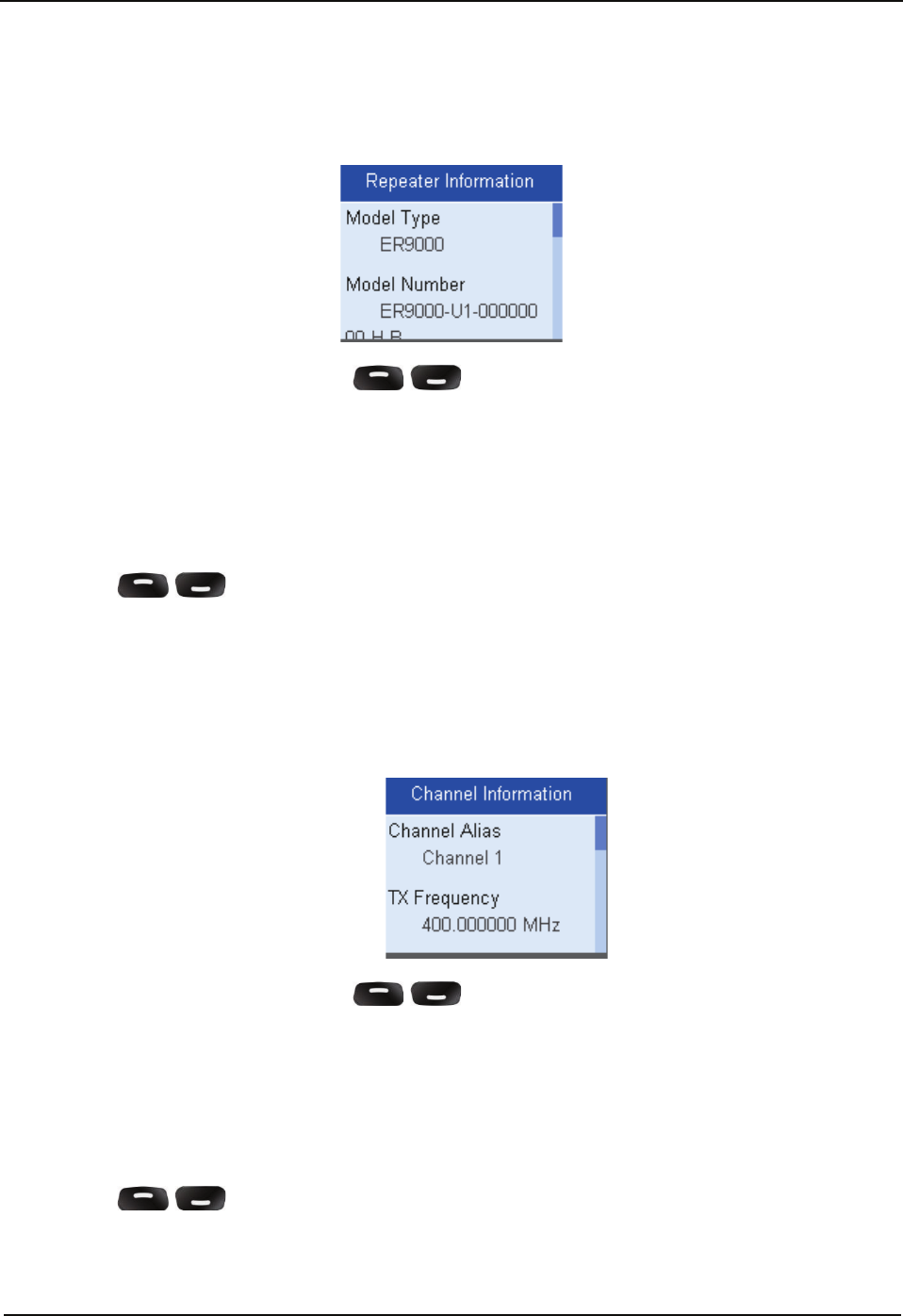
Repeater Information
Under this menu, you can use the / key to view repeater information, including
Model Type, Model Number, Data Version, and Firmware Version.
Follow the procedures below to view repeater information.
Procedure:
1. In the home screen, press the SET key to enter the main menu.
2. Use the / key to select the “Repeater Information” option.
3. Press the SET key to view basic information of the repeater.
To exit this menu, press the EXIT key.
Channel Information
Under this menu, you can use the / key to view channel information, including
Channel Alias and TX Frequency.
Follow the procedures below to view channel information.
Procedure:
1. In the home screen, press the SET key to enter the main menu.
2. Use the / key to select the “Channel Information” option.
3. Press the SET key to view channel information.
To exit this menu, press the EXIT key.
Menu Navigation
23
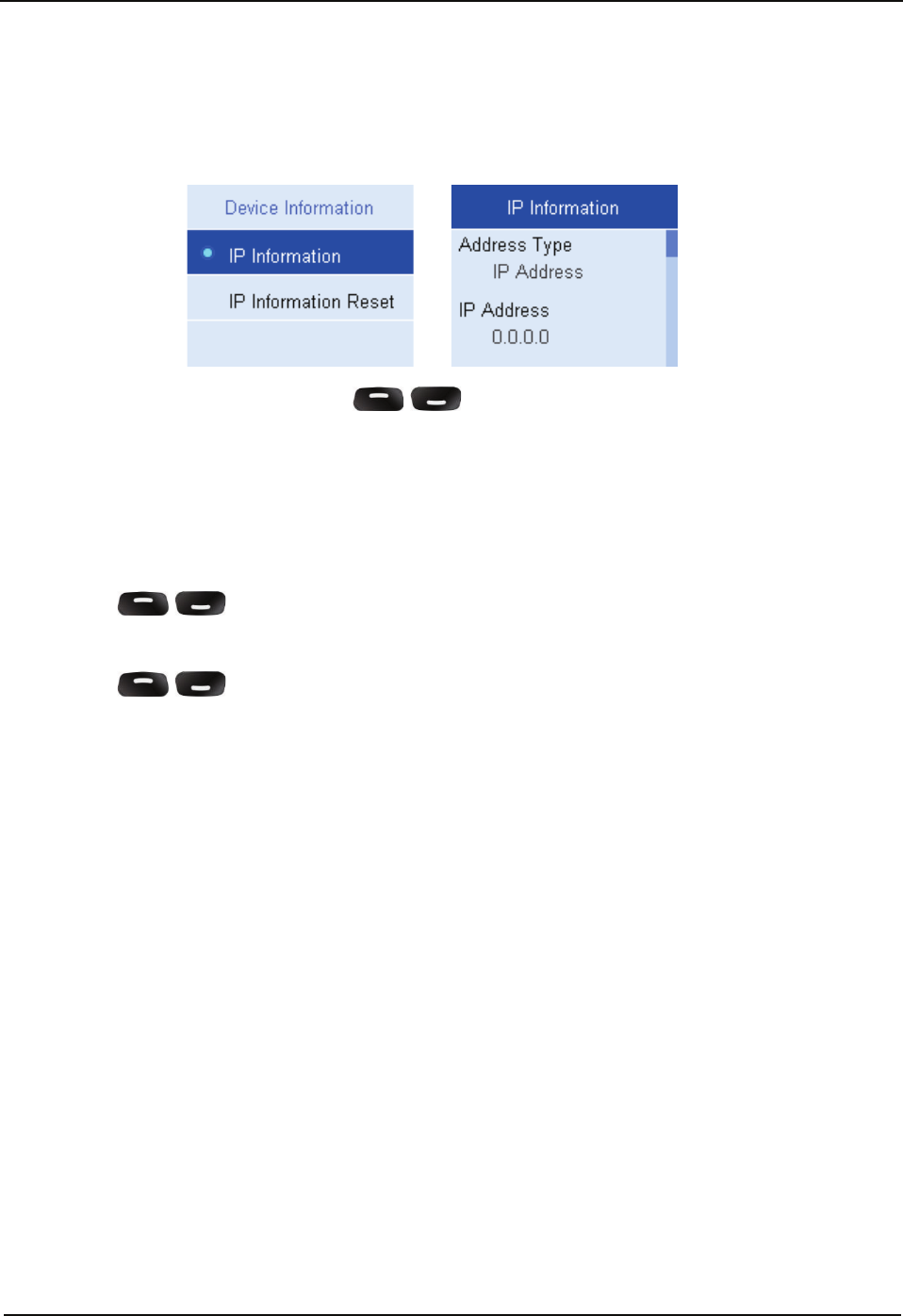
Device Information
IP Information
Under this menu, you can use the / key to view IP information, including
Address Type, IP Address, Subnet Mask, Default Gateway, and MAC Address.
Follow the procedures below to view IP information.
Procedure:
1. In the home screen, press the SET key to enter the main menu.
2. Use the / key to select the “Device Information” option.
3. Press the SET key to enter the Device Information menu.
4. Use the / key to select the “IP Information” option.
5. Press the SET key to view IP information.
To exit this menu, press the EXIT key.
Menu Navigation
24
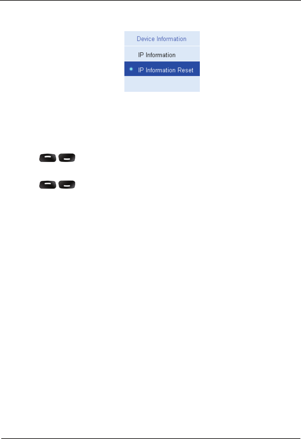
IP Information Reset
Under this menu, you can restore IP information to factory defaults.
Follow the procedures below to restore IP information to factory defaults.
Procedure:
1. In the home screen, press the SET key to enter the main menu.
2. Use the / key to select the “Device Information” option.
3. Press the SET key to enter the Device Information menu.
4. Use the / key to select the “IP Information Reset” option.
5. Press the SET key to restore IP information to factory defaults.
To exit this menu, press the EXIT key.
Alarm Information
25
Alarm Information
The repeater can automatically detect its operation status in a real time way. When an
abnormality occurs, the LCD display will give you a prompt message, and the Alarm
Indicator will glow red.
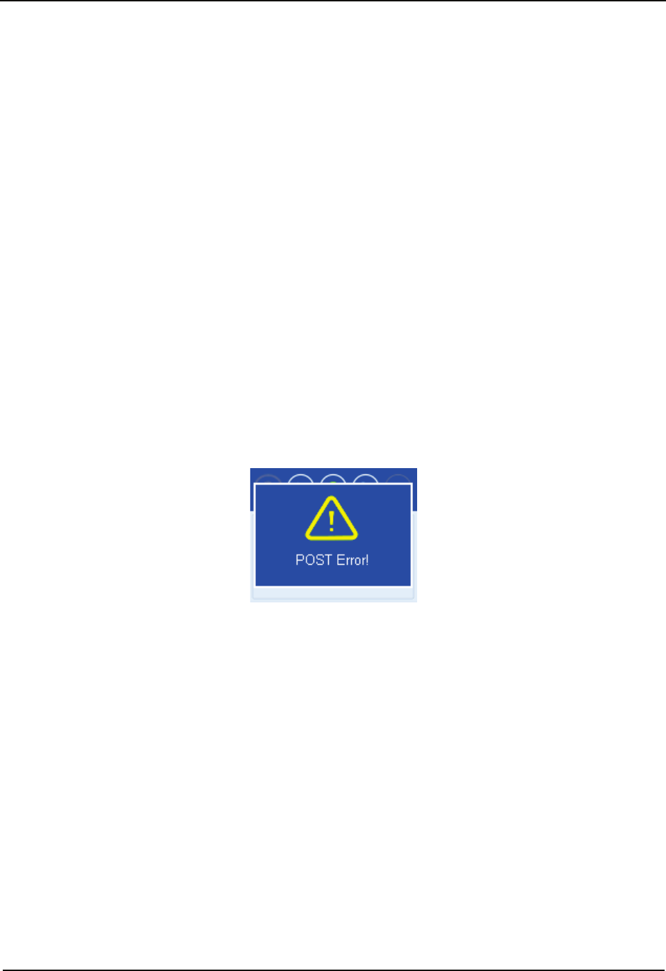
POST Error Alarm
The principal duties of the system during POST are as follows:
verify fan
verify LCD display
verify TX circuit
verify RX circuit
verify active duplexer circuit
When an error occurs during POST, abnormality of partial functions happens and the
system runs normally. In addition, the Alarm Indicator will glow red and the LCD display
will give you the prompt message below:
You need to:
1. Disconnect the power supply, open the chassis, and check whether the LCD display is
properly connected or damaged.
2. Disconnect the power supply and open the chassis to check whether the fan works
properly.
3. Disconnect the power supply and open the chassis to check if the hardware cable gets
loose or damaged. If yes, secure or replace the hardware cable.
4. If you cannot solve the problem, contact your local dealer for technical support.

Alarm Information
26
Over Temperature Alarm
When the temperature of the PA module exceeds the normal range, the Alarm Indicator
will glow red and the LCD display will give you the prompt message below:
Then the repeater will stop transmitting, and you need to:
1. Check whether the Fan Failure Alarm prompt message appears on the LCD display.
If yes, refer to measures taken in Fan Failure Alarm.
2. Check whether ambient temperature and ventilation conditions satisfy the foregoing
installation requirements. If not, please make improvements as soon as possible. For
example, install more air conditioners for optimal ventilation.
3. Check if the RF cable or antenna feeder that is connected to the transmitter is loose or
damaged. Poor connection between them could cause high TX power. If yes, secure or
replace the cable or antenna feeder.
4. If the above measures fail to solve the problem, contact your local dealer for technical
support.
When repeater temperature falls into normal range, the prompt message will disappear
and the Alarm Indicator will go out.
Alarm Information
27
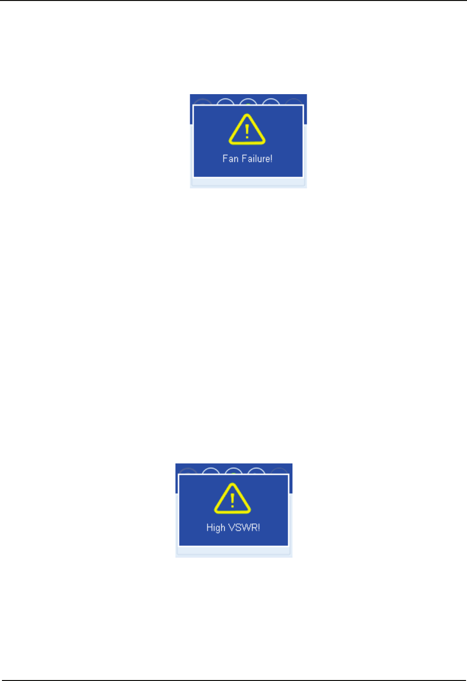
Fan Failure Alarm
When the fan fails to work, the Alarm Indicator will glow red and the LCD display will give
you the prompt message below:
Then the repeater will automatically work at low TX power to protect the transmitter from
overheating.
You need to:
1. Check whether the fan is blocked by an object. If yes, remove it.
2. If you cannot solve the problem, contact your local dealer for technical support.
When the fan restores to normal operation, the prompt message will disappear and the
Alarm Indicator will go out.
VSWR Alarm
High voltage standing wave ratio (VSWR) of TX antenna connector could result in damage
to the PA, and even failure of the transmitter. When the VSWR exceeds the normal range,
the Alarm Indicator will glow red and the LCD display will give you the prompt message
below:
Then the repeater will automatically works at low TX power.
You need to:
1. Check whether the operating frequency of the repeater is in line with that of antenna.
Both frequency mismatch and improper antenna could result in poor transmitting
performance and even damage to the transmitter. If yes, please contact your local
dealer to replace the antenna or program the repeater again.
Alarm Information
28
2. Check if the RF cable or antenna feeder that is connected to the transmitter gets loose
or damaged. If yes, secure or replace the cable or antenna feeder.
3. If you fail to solve the problem, contact your local dealer for technical support.
When the VSWR falls within the normal range, the prompt message will disappear and
the Alarm Indicator will go out.
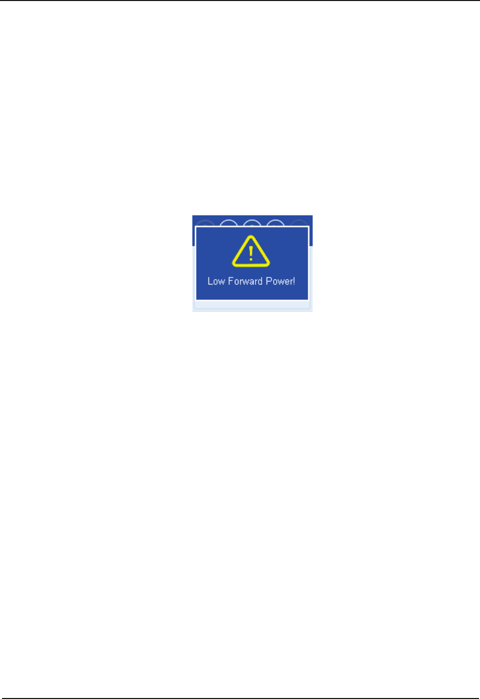
Low Forward Power Alarm
When the forward power is below the preset value, the Alarm Indicator will glow red and
the LCD display will give you the prompt message below:
Then the repeater may continue transmission or terminate it according to the detected
result.
You need to:
1. Check if the RF cable or antenna feeder that is connected to the transmitter gets loose
or damaged. If yes, secure or replace the cable or antenna feeder.
2. If you cannot solve the problem, contact your local dealer for technical support.
When the forward power is restored to its normal value, the prompt message will
disappear and the Alarm Indicator will go out.
Alarm Information
29
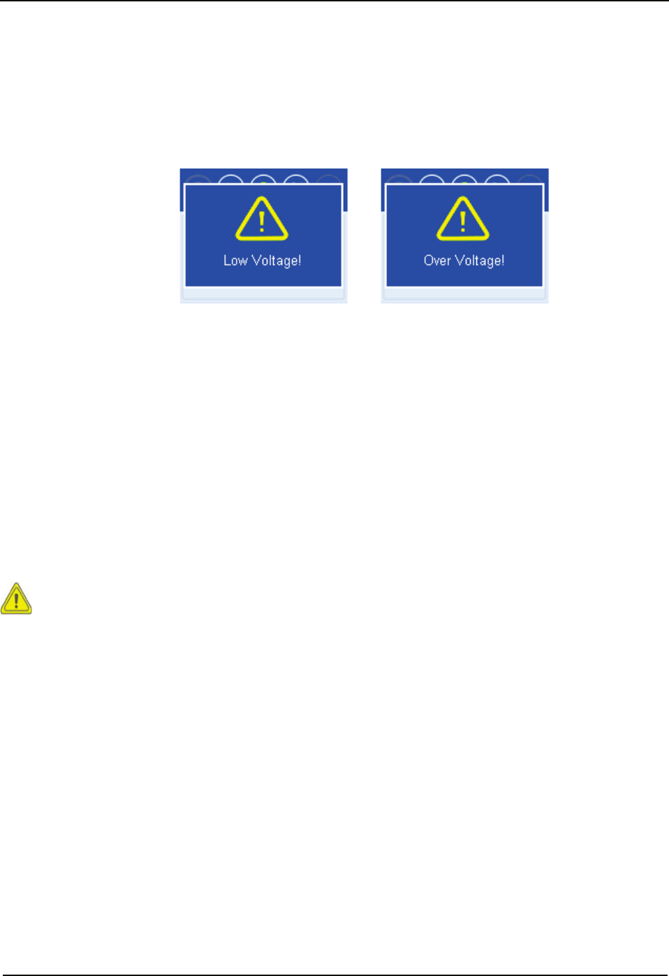
Over/Low Voltage Alarm
When power voltage is detected to be over or below the normal range (10.8V-15.6V) of
repeater, the Alarm Indicator will glow red and the LCD display will give you the prompt
message below:
Low Voltage Alarm Over Voltage Alarm
Then the repeater will automatically stop working and the prompt message will remain on
the LCD display.
You need to:
1. Check whether the power voltage is too low or too high. If yes, replace the DC power
supply or external battery.
2. Check if the power cord gets loose or damaged. If yes, secure or replace the cord.
3. If you fail to solve the problem, contact your local dealer for technical support.
Caution: If low voltage is detected when the repeater is powered by an external
battery, please charge it in time. Disconnect the battery from the repeater before
charging.
Alarm Information
30
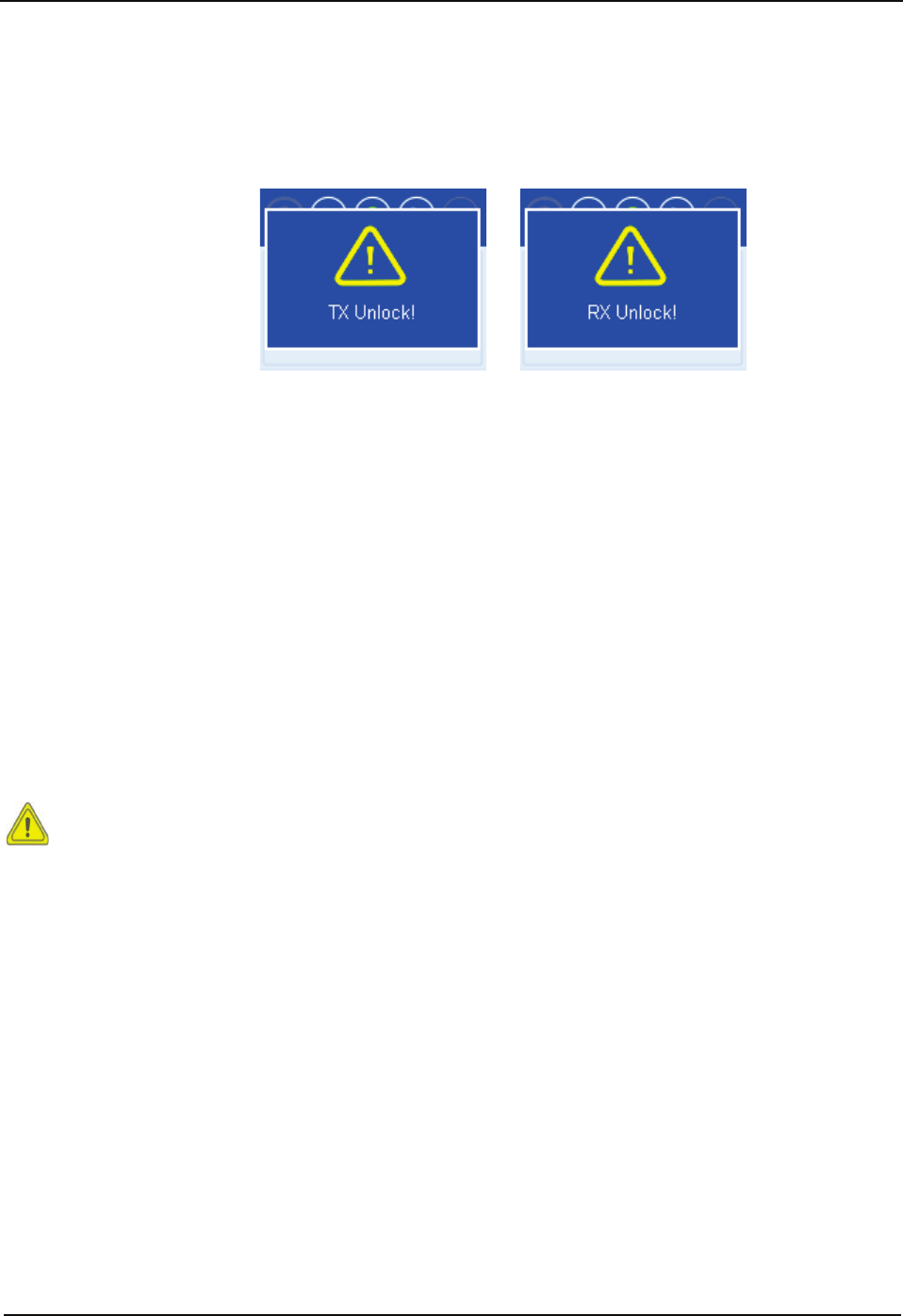
TX/RX Unlock Alarm
When the TX/RX PLL is unlocked, the Alarm Indicator will glow red and the LCD display
will give you the prompt message below:
TX Unlock Alarm RX Unlock Alarm
Then the repeater will automatically stop partial operations and the prompt message will
remain on the LCD display.
You need to:
1. Disconnect the power supply, open the chassis, and check whether the hardware cable
gets loose or damaged. If yes, please secure or replace the cable.
2. If you cannot solve the problem, contact your local dealer for technical support.
When the TX/RX PLL restores to normal operation, the prompt message will disappear
and the Alarm Indicator will go out.
Caution: Disconnect the power supply prior to opening the chassis!
Optional Accessories
31
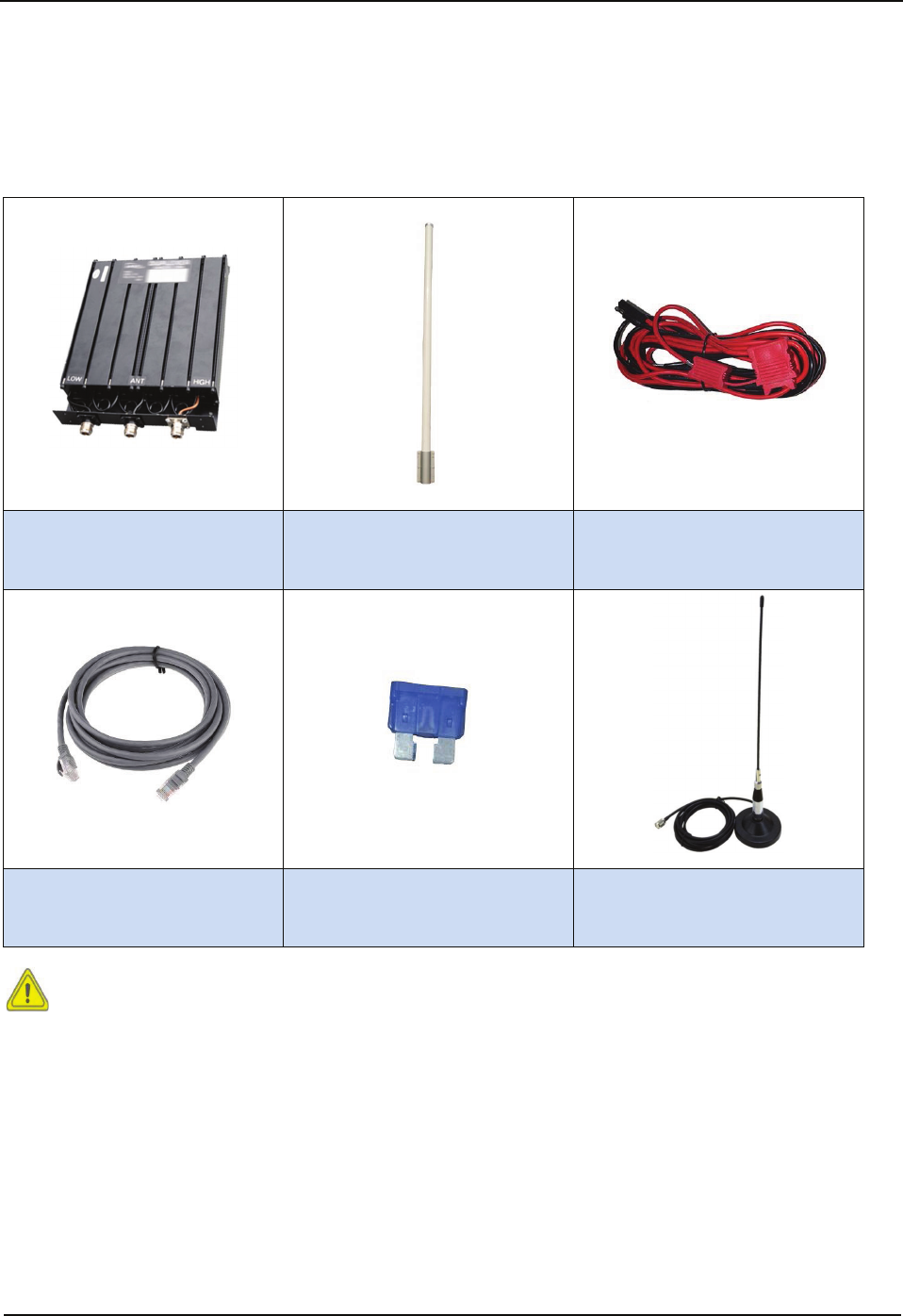
Optional Accessories
The following items are the main optional accessories for the product. Please contact us at
+86-10-67869119 for more information.
Auto Tune Duplexer
EDU001
Fiberglass Antenna
EAD000001
Power Cord
EPWCAZ01
Programming Cable
EPC03
Fuse
EACC001
Mobile Antenna
EAM434401
Caution: Use the accessories specified by the Company only. If not, we shall not be
liable for any damage arising out of use of unauthorized accessories.

Troubleshooting
32
Troubleshooting
Phenomena Analysis Solution
The repeater cannot be powered
on.
Power cord is not connected
or is not securely connected to
the outlet.
Properly connect the power cord
and secure connection.
Power cord fuse is damaged.
Check whether the fuse has
blown. If yes, replace it with a
new one.
Group members cannot talk to
each other, or the repeater
cannot communicate with a
subscriber radio.
TX/RX frequency of the
repeater is inconsistent with
that of portable/mobile
terminals.
Reset frequencies.
Failed to repeat useful signal
due to strong interference
signal.
If you cannot remove or bypass
the interference source, change
or operate at other frequencies.
The group member is out of
the coverage of the repeater.
Go within the coverage of the
repeater.
Group members cannot talk to
each other, even though RX
indication is given.
Your ID is inconsistent with
that of other group members.
Set your ID to be the same as
that of other members.
Inconsistent CTCSS/CDCSS Reset CTCSS/CDCSS.
Short communication range or
poor audio
Leakage of signal energy due
to damaged connection cable.
Replace the cable with a new
one if necessary.
Loose connection between the
antenna connector and the
cable, or loss of connection
Secure or replace the cable.
Invisible damage of cable Replace the cable with a new
one.
Duplexer is not properly set (if
the duplexer is mounted).
Contact the manufacturer or your
dealer to reset the duplexer.
If the above solutions cannot fix your problems, or you may have some other queries,
please contact us or your local dealer for more technical support.

Care and Cleaning
33
Care and Cleaning
To guarantee optimal performance as well as a long service life of the product, please
follow the tips below. Power off the repeater or disconnect it from the external battery
before cleaning.
Product Care
Keep the product at a place of good ventilation and heat dissipation to facilitate normal
work.
Do not place irrelevant articles on the top of the product to ensure optimal heat
dissipation.
Do not pierce or scrape the product with any edged instruments or hard objects.
Keep the product far away from substances that can corrode the circuit.
Do not place the product in corrosive agents, solutions, or water.
Product Cleaning
Remove the dust and fine particles on the repeater surface with a clean and dry
lint-free cloth or a brush regularly.
Use a non-woven cloth with neutral cleanser to clean the keys, control knobs, LCD,
and connectors after long-time use. Never use chemical preparations such as stain
removers, alcohol, sprays, or oil preparations. Make sure the product is completely dry
before use.

Limited Warranty
34
Limited Warranty
What This Warranty Covers and for How Long
Shenzhen Excera Technology Co., Ltd. warrants the Excera manufactured products listed
below against defects in material and workmanship under normal use and service for a
period of time from the date of purchase as scheduled below:
ER9000 Digital Repeaters Two Years
Accessories Six Months
How to Get Warranty Service
You must provide a completely filled warranty card, purchase invoice, and receipt in order
to get warranty services. The purchase invoice or receipt should indicate the repeater,
accessories, repeater serial number, purchase date, and purchase amount.
What This Warranty Does Not Cover
1. Defect or damage resulting from use of the product in other than its normal and
customary manner
2. Defect or damage caused by unauthorized product disassembly, repair, or
modification
3. Damage due to force majeure, such as flood, lightning strike, earthquake, tsunami, fire,
and abnormal voltage
4. Product that does not have proof of purchase, such as warranty card, purchase
invoice, or receipt
5. Product which has had the serial number and the tamper-proof label removed or made
illegible
6. Normal and customary wear and tear
Disclaimer
35
Disclaimer
The information in this manual is carefully examined and is believed to be entirely reliable.
However, no responsibility is assumed for inaccuracies. All the specifications and designs
are subject to change without notice due to continuous technology development. No part
of this manual may be copied, modified, translated, or distributed in any manner without
the prior written permission of the Company.
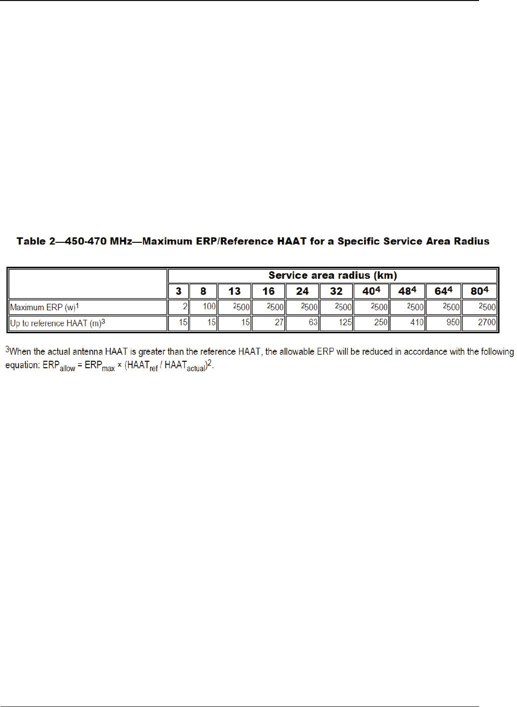
5)+LJK3RZHU:5)/RZ3RZHU:
7KHPD[LPXPDOORZDEOHVWDWLRQHIIHFWLYHUDGLDWHGSRZHU(53LVGHSHQGHQWXSRQWKHVWDWLRQV
DQWHQQD+$$7DQGUHTXLUHGVHUYLFHDUHDDQGZLOOEHDXWKRUL]HGLQDFFRUGDQFHZLWKWDEOH

Warranty Card
36
Warranty Card
Purchase Information
Customer Name:
Customer Phone:
Customer Address:
Purchase Date:
Repeater Information
Model Number:
Serial Number:
Note:
This warranty card applies to after-sale and maintenance services for the product and
accessories described above.
You must provide this warranty card and purchase invoice in order to get warranty
services.
The Company does not assume liability for damages caused by human factors. For
more details, contact your local dealer.

37