Exmark Lazer Z X Series Commercial Mowers 0 Users Manual
!! Exmark-21 Exmark Lawn Mower Manuals - Lawn Mower Manuals – The Best Lawn Mower Manuals Collection
LZX680KC486; LZX740KC526; LZX740KC606; LZX740KC606CA; LZX749EKC606; LZX801KA606; LZX801KA606SS; LZX940KC606; LZX940KC726; LZX980 to the manual 4ef6f6da-578f-4c98-96ab-c7d312ec44df
2015-02-04
: Exmark Exmark-Exmark-Lazer-Z-X-Series-Commercial-Mowers-0-Users-Manual-366892 exmark-exmark-lazer-z-x-series-commercial-mowers-0-users-manual-366892 exmark pdf
Open the PDF directly: View PDF ![]() .
.
Page Count: 64

LAZERZ®X-SERIES
ForSerialNos.
312,000,000&Higher
LazerZ(LZX)Units
PartNo.4501-196Rev.A

WARNING
CALIFORNIA
Proposition65Warning
Theengineexhaustfromthisproduct
containschemicalsknowntotheStateof
Californiatocausecancer,birthdefects,
orotherreproductiveharm.
Important:Theengineinthisproductisnot
equippedwithasparkarrestermufer.Itisa
violationofCaliforniaPublicResourceCode
(CPRC)Section4442touseoroperatethis
engineonanyforest-covered,brush-covered,
orgrass-coveredlandasdenedinCPRC4126.
Otherstatesorfederalareasmayhavesimilar
laws.
Toacquireasparkarresterforyourunit,seeyour
EngineServiceDealer.
Thissparkignitionsystemcomplieswiththe
CanadianstandardICES-002.Cesystèmed’allumage
parètincelledevèhiculeestconformeàlanorme
NMB-002duCanada.
TheenclosedEngineOwner’sManualis
suppliedforinformationregardingTheU.S.
EnvironmentalProtectionAgency(EPA)and
theCaliforniaEmissionControlRegulationof
emissionsystems,maintenanceandwarranty.
KeepthisengineOwner’sManualwithyourunit.
ShouldthisengineOwner’sManualbecome
damagedorillegible,replaceimmediately.
Replacementsmaybeorderedthroughthe
enginemanufacturer.
Exmarkreservestherighttomakechangesor
addimprovementstoitsproductsatanytime
withoutincurringanyobligationtomakesuch
changestoproductsmanufacturedpreviously.
Exmark,oritsdistributorsanddealers,accept
noresponsibilityforvariationswhichmaybe
evidentintheactualspecicationsofitsproducts
andthestatementsanddescriptionscontained
inthispublication.
©2012ExmarkMfg.Co.,Inc.
IndustrialParkBox808
Beatrice,NE683102
Contactusatwww.Exmark.com.
PrintedintheUSA
AllRightsReserved
Introduction
CONGRATULATIONSonthepurchaseofyour
ExmarkMower.Thisproducthasbeencarefully
designedandmanufacturedtogiveyouamaximum
amountofdependabilityandyearsoftrouble-free
operation.
Thismanualcontainsoperating,maintenance,
adjustment,andsafetyinstructionsforyourExmark
mower.
BEFOREOPERATINGYOURMOWER,
CAREFULLYREADTHISMANUALINITS
ENTIRETY.
Byfollowingtheoperating,maintenance,andsafety
instructions,youwillprolongthelifeofyourmower,
maintainitsmaximumefciency,andpromotesafe
operation.
Ifadditionalinformationisneeded,orshould
yourequiretrainedmechanicservice,contactyour
authorizedExmarkequipmentdealerordistributor.
Exmarkpartsmanualsareavailableonlineat
http://www.exmark.com
AllExmarkequipmentdealersanddistributorsare
keptinformedofthelatestmethodsofservicing
andareequippedtoprovidepromptandefcient
serviceintheeldorattheirservicestations.They
carryamplestockofservicepartsorcansecurethem
promptlyforyoufromthefactory.
AllExmarkpartsarethoroughlytestedandinspected
beforeleavingthefactory,however,attentionis
requiredonyourpartifyouaretoobtainthefullest
measureofsatisfactionandperformance.
Wheneveryouneedservice,genuineExmarkparts,
oradditionalinformation,contactanAuthorized
ServiceDealerorExmarkCustomerServiceandhave
themodelandserialnumbersofyourproductready.
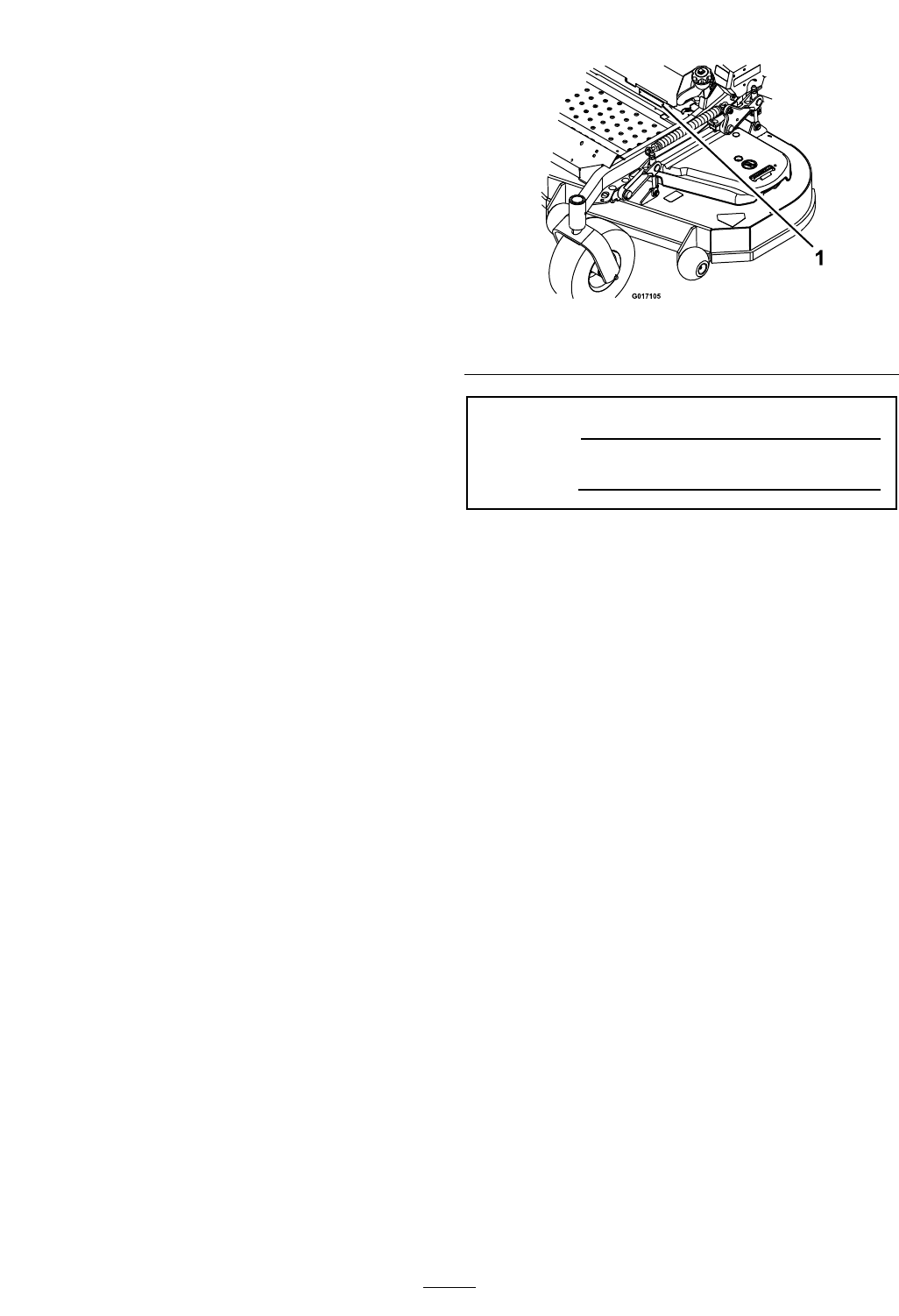
Figure1identiesthelocationofthemodelandserial
numbersontheproduct.Writethenumbersinthe
spaceprovided.
Figure1
1.Modelandserialnumberlocation
ModelNo.
SerialNo.
3

Contents
Introduction...........................................................3
Safety.....................................................................5
SafetyAlertSymbol.........................................5
SafeOperatingPractices..................................5
SafetyandInstructionalDecals......................11
Specications........................................................16
ModelNumbers.............................................16
Systems..........................................................16
Dimensions....................................................18
TorqueRequirements.....................................20
ProductOverview.................................................20
Operation..............................................................21
Controls.........................................................21
Pre-Start.........................................................24
OperatingInstructions...................................24
Transporting..................................................28
Maintenance..........................................................30
RecommendedMaintenanceSchedule(s)............30
PeriodicMaintenance........................................31
CheckEngineOilLevel..................................31
CheckMowerBlades......................................33
CheckSafetyInterlockSystem........................34
CheckRolloverProtectionsSystems(Roll
Bar)Knobs.................................................34
CheckSeatBelt...............................................35
CheckforLooseHardware.............................35
ServiceAirCleaner.........................................35
ChangeEngineOil.........................................35
CheckHydraulicOilLevel..............................36
CheckTirePressures......................................36
CheckConditionOfBelts...............................36
LubricateGreaseFittings................................37
LubricateDeckLiftPivot...............................38
CheckSparkPlugs..........................................38
ChangeHydraulicSystemFilterand
Fluid..........................................................38
WheelHub-SlottedNutTorque
Specication...............................................39
CheckSparkArrester(ifequipped)..................39
ThreadLockingAdhesives..............................39
MobilHTSGrease(OrFood-Grade
Anti-seize)..................................................39
Copper-BasedAnti-seize...............................40
DielectricGrease............................................40
Adjustments......................................................40
DeckLeveling................................................40
PumpDriveBeltTension................................42
DeckBeltTension..........................................42
AdjustingtheParkingBrake............................42
ElectricClutchAdjustment.............................43
MotionControlLinkageAdjustment..............44
MotionControlDamperAdjustment..............45
MotionControlNeutralLockPivot
Adjustment................................................46
MotionControlHandleAdjustment...............46
MotionControlFullForwardTracking
Adjustment................................................46
CasterPivotBearingsPre-Load
Adjustment................................................47
Cleaning............................................................48
CleanEngineandExhaustSystem
Area...........................................................48
RemoveEngineShroudsandClean
CoolingFins...............................................48
CleanHydroFanCoolingGuards...................48
CleanDebrisFromMachine...........................48
CleanGrassBuild-UpUnderDeck.................48
WasteDisposal...............................................49
Troubleshooting....................................................50
Schematics............................................................53
4

Safety
Safety
SafetyAlertSymbol
ThislawnmowermeetsorexceedstheB71.4
specicationsoftheAmericanNationalStandards
Instituteineffectatthetimeofproduction.
Exmarkdesignedandtestedthislawnmowertooffer
reasonablysafeservice;however,failuretocomply
withthefollowinginstructionsmayresultinpersonal
injury.
ThisSafetyAlertSymbol(Figure2)isusedbothin
thismanualandonthemachinetoidentifyimportant
safetymessageswhichmustbefollowedtoavoid
accidents.
Thissymbolmeans:ATTENTION!BECOME
ALERT!YOURSAFETYISINVOLVED!
Figure2
SafetyAlertSymbol
Thesafetyalertsymbolappearsaboveinformation
whichalertsyoutounsafeactionsorsituations
andwillbefollowedbythewordDANGER,
WARNING,orCAUTION.
DANGER:Whitelettering/Redbackground.
Indicatesanimminentlyhazardoussituationwhich,if
notavoided,Willresultindeathorseriousinjury.
WARNING:Blacklettering/Orangebackground.
Indicatesapotentiallyhazardoussituationwhich,if
notavoided,Couldresultindeathorseriousinjury.
CAUTION:Blacklettering/Yellowbackground.
Indicatesapotentiallyhazardoussituationwhich,if
notavoided,Mayresultinminorormoderateinjury.
Thismanualusestwootherwordstohighlight
information.Importantcallsattentiontospecial
mechanicalinformationandNoteemphasizes
generalinformationworthyofspecialattention.
SafeOperatingPractices
Training
•ReadtheOperator’sManualandothertraining
material.Iftheoperator(s)ormechanic(s)can
notreadEnglishitistheowner’sresponsibilityto
explainthismaterialtothem.
•Becomefamiliarwiththesafeoperationofthe
equipment,operatorcontrols,andsafetysigns.
•Alloperatorsandmechanicsshouldbetrained.
Theownerisresponsiblefortrainingtheusers.
•Neverletchildrenoruntrainedpeopleoperate
orservicetheequipment.Localregulationsmay
restricttheageoftheoperator.
•Onlyadultsandmatureteenagersshouldoperate
amower,andevenmatureteenagersshouldhave
adultsupervision.Besureateenager:
1.hasreadandunderstandstheOperator's
Manualandrecognizestherisksinvolved;
2.issufcientlymaturetousecaution;and
3.isofsufcientsizeandweighttooperate
thecontrolscomfortablyandtomanagethe
mowerwithouttakingrisks.
•Theowner/usercanpreventandisresponsible
foraccidentsorinjuriesoccurringtohimselfor
herself,otherpeopleorproperty.
Preparation
•Evaluatetheterraintodeterminewhataccessories
andattachmentsareneededtoproperlyand
safelyperformthejob.Onlyuseaccessoriesand
attachmentsapprovedbyExmark.
•Wearappropriateclothingincludingsafetyglasses,
substantialfootwear,longtrousers,andhearing
protection.DoNotoperatewhenbarefootor
whenwearingopensandals.Longhair,loose
clothingorjewelrymaygettangledinmoving
parts.
CAUTION
Thismachineproducessoundlevelsinexcess
of85dBAattheoperator’searandcancause
hearinglossthroughextendedperiodsof
exposure.
Wearhearingprotectionwhenoperatingthis
machine.
5

Safety
•Inspecttheareawheretheequipmentistobe
usedandremoveallrocks,toys,sticks,wires,
bones,andotherforeignobjectswhichcanbe
thrownbythemachineandmaycausepersonal
injurytotheoperatororbystanders.
DANGER
Incertainconditionsgasolineisextremely
ammableandvaporsareexplosive.
Areorexplosionfromgasolinecanburn
you,others,andcausepropertydamage.
•Fillthefueltankoutdoorsonlevelground,
inanopenarea,whentheengineiscold.
Wipeupanygasolinethatspills.
•Neverrellthefueltankordrainthe
machineindoorsorinsideanenclosed
trailer.
•DoNotllthefueltankcompletelyfull.
Fillthefueltanktothebottomoftheller
neck.Theemptyspaceinthetankallows
gasolinetoexpand.Overllingmayresult
infuelleakageordamagetotheengine
oremissionsystem.
•Neversmokewhenhandlinggasoline,and
stayawayfromanopenameorwhere
gasolinefumesmaybeignitedbyspark.
•Storegasolineinanapprovedcontainer
andkeepitoutofthereachofchildren.
•Addfuelbeforestartingtheengine.Never
removethecapofthefueltankoradd
fuelwhenengineisrunningorwhenthe
engineishot.
•Iffuelisspilled,DoNotattempttostart
theengine.Moveawayfromtheareaof
thespillandavoidcreatinganysourceof
ignitionuntilfuelvaporshavedissipated.
•DoNotoperatewithoutentireexhaust
systeminplaceandinproperworking
condition.
DANGER
Incertainconditionsduringfueling,static
electricitycanbereleasedcausingaspark
whichcanignitegasolinevapors.Areor
explosionfromgasolinecanburnyouand
othersandcausepropertydamage.
•Alwaysplacegasolinecontainersonthe
groundawayfromyourvehiclebefore
lling.
•DoNotllgasolinecontainersinsidea
vehicleoronatruckortrailerbedbecause
interiorcarpetsorplastictruckbedliners
mayinsulatethecontainerandslowthe
lossofanystaticcharge.
•Whenpractical,removegas-powered
equipmentfromthetruckortrailerand
refueltheequipmentwithitswheelson
theground.
•Ifthisisnotpossible,thenrefuelsuch
equipmentonatruckortrailerfroma
portablecontainer,ratherthanfroma
gasolinedispensernozzle.
•Ifagasolinedispensernozzlemustbe
used,keepthenozzleincontactwiththe
rimofthefueltankorcontaineropening
atalltimesuntilfuelingiscomplete.
WARNING
Gasolineisharmfulorfatalifswallowed.
Long-termexposuretovaporshascaused
cancerinlaboratoryanimals.Failuretouse
cautionmaycauseseriousinjuryorillness.
•Avoidprolongedbreathingofvapors.
•Keepfaceawayfromnozzleandgas
tank/containeropening.
•Keepawayfromeyesandskin.
•Neversiphonbymouth.
6

Safety
CAUTION
Fueltankventislocatedinsidetheroll
bartube.Removingormodifyingtheroll
barcouldresultinfuelleakageandviolate
emissionsregulations.
•DoNotremoverollbar.
•DoNotweld,drill,ormodifyrollbarin
anyway.
•Checkthattheoperator'spresencecontrols,
safetyswitches,andshieldsareattachedand
functioningproperly.DoNotoperateunlessthey
arefunctioningproperly.
Operation
WARNING
Operatingengineparts,especiallythemufer,
becomeextremelyhot.Severeburnscanoccur
oncontactanddebris,suchasleaves,grass,
brush,etc.cancatchre.
•Allowengineparts,especiallythemufer,to
coolbeforetouching.
•Removeaccumulateddebrisfrommuferand
enginearea.
•Installandmaintaininworkingordera
sparkarresterbeforeusingequipment
onforest-covered,grass-covered,or
brush-coveredunimprovedland.
WARNING
Engineexhaustcontainscarbonmonoxide,
whichisanodorlessdeadlypoisonthatcankill
you.
DoNotrunengineindoorsorinasmallconned
areawheredangerouscarbonmonoxidefumes
cancollect.
•Operateonlyindaylightorgoodarticiallight,
keepingawayfromholesandhiddenhazards.
•Besurealldrivesareinneutralandparkingbrake
isengagedbeforestartingengine.Useseatbelts
withtherollbarintheraisedandlockedposition.
•Neveroperatethemowerwithdamagedguards,
shields,orcovers.Alwayshavesafetyshields,
guards,switchesandotherdevicesinplaceandin
properworkingcondition.
•Nevermowwiththedischargedeectorraised,
removedoralteredunlessthereisagrass
collectionsystemormulchkitinplaceand
workingproperly.
•DoNotchangetheenginegovernorsettingor
overspeedtheengine.
•Parkmachineonlevelground.Stopengine,wait
forallmovingpartstostop,removekeyand
engageparkingbrake:
–Beforechecking,cleaningorworkingonthe
mower.
–Afterstrikingaforeignobjectorabnormal
vibrationoccurs(inspectthemowerfor
damageandmakerepairsbeforerestarting
andoperatingthemower).
–Beforeclearingblockages.
–Wheneveryouleavethemower.
•Stopengine,waitforallmovingpartstostop,and
engageparkingbrake:
–Beforerefueling.
–Beforedumpingthegrasscatcher.
WARNING
Hands,feet,hair,clothing,oraccessoriescan
becomeentangledinrotatingparts.Contact
withtherotatingpartscancausetraumatic
amputationorseverelacerations.
•DoNotoperatethemachinewithout
guards,shields,andsafetydevicesinplace
andworkingproperly.
•Keephands,feet,hair,jewelry,orclothing
awayfromrotatingparts.
•NEVERcarrypassengers.DONOToperate
themowerwhenpeople,especiallychildren,or
petsareinthearea.
•Bealert,slowdownandusecautionwhen
makingturns.Lookbehindandtothesidebefore
changingdirections.
•Stoptheblades,slowdown,andusecaution
whencrossingsurfacesotherthangrassandwhen
transportingthemowertoandfromtheareato
bemowed.
•Beawareofthemowerdischargepathanddirect
dischargeawayfromothers.
7
Safety
•DoNotoperatethemowerundertheinuence
ofalcoholordrugs.
•Useextremecarewhenloadingorunloadingthe
machineintoatrailerortruck.
•Usecarewhenapproachingblindcorners,shrubs,
trees,orotherobjectsthatmayobscurevision.
SlopeOperation
UseExtremecautionwhenmowingand/orturning
onslopesaslossoftractionand/ortip-overcould
occur.Theoperatorisresponsibleforsafeoperation
onslopes.
DANGER
Operatingonwetgrassorsteepslopescancause
slidingandlossofcontrol.Wheelsdroppingover
edges,ditches,steepbanks,orwatercancause
rollovers,whichmayresultinseriousinjury,
deathordrowning.
•DoNotmowslopeswhengrassiswet.
•DoNotmowneardrop-offsornearwater.
•DoNotmowslopesgreaterthan15degrees.
•Reducespeedanduseextremecautionon
slopes.
•Avoidsuddenturnsorrapidspeedchanges.
•Keeptherollbarintheraisedandlocked
positionanduseseatbelt.
•Seeinsidethebackcovertodeterminethe
approximateslopeangleoftheareatobemowed.
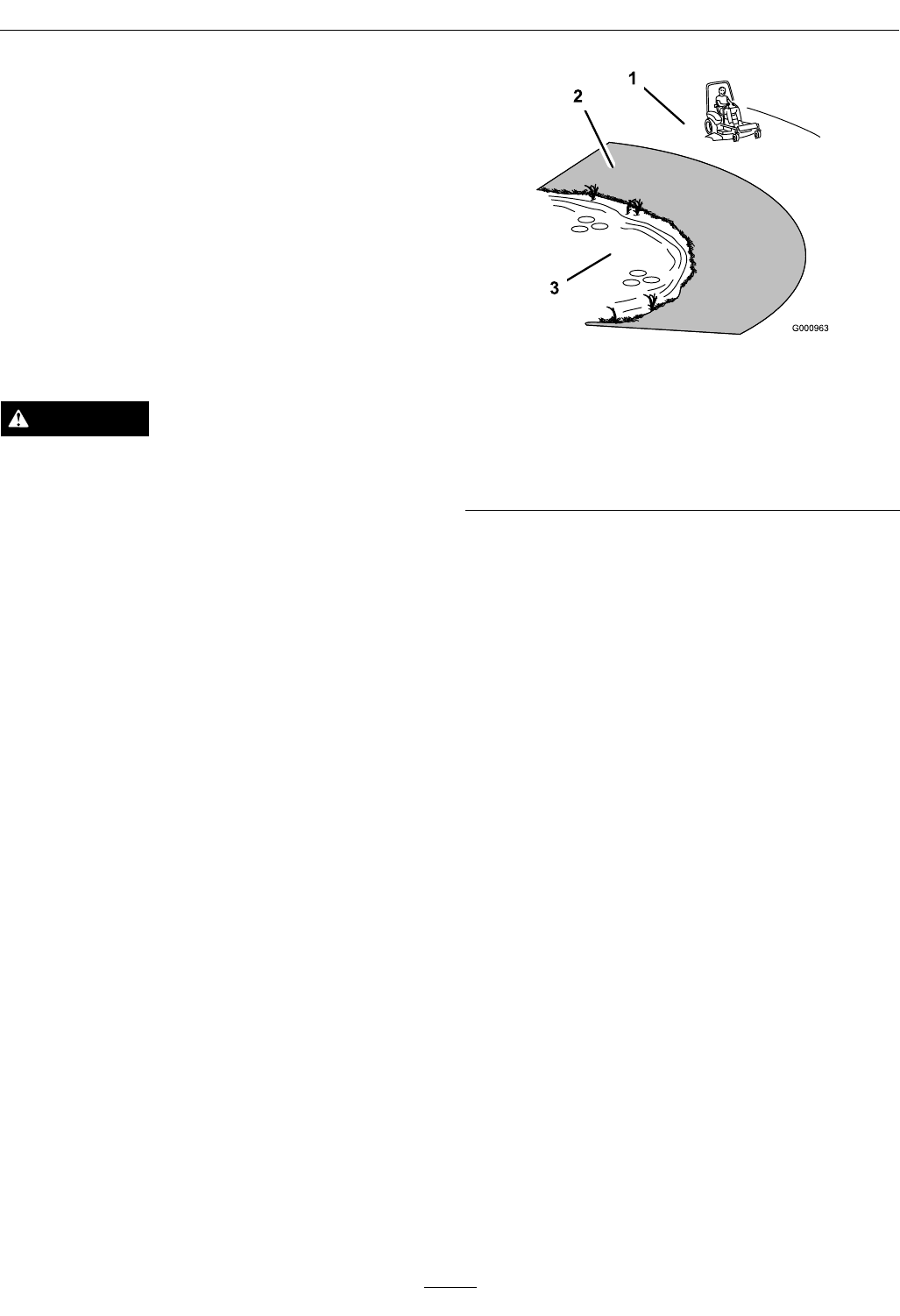
•Useawalkbehindmowerand/orahandtrimmer
neardrop-offs,ditches,steepbanksorwater.
(Figure3).
Figure3
1.SafeZone-Usethemowerhereonslopeslessthan15
degrees
2.DangerZone-Useawalkbehindmowerand/orhand
trimmeronslopesgreaterthan15degrees,near
drop-offsandwater.
3.Water
•Removeormarkobstaclessuchasrocks,tree
limbs,etc.fromthemowingarea.Tallgrasscan
hideobstacles.
•Watchforditches,holes,rocks,dipsandrisesthat
changetheoperatingangle,asroughterraincould
overturnthemachine.
•Avoidsuddenstartswhenmowinguphillbecause
themowermaytipbackwards.
•Beawarethatoperatingonwetgrass,acrosssteep
slopesordownhillmaycausethemowertolose
traction.Lossoftractiontothedrivewheelsmay
resultinslidingandalossofbrakingandsteering.
•Alwaysavoidsuddenstartingorstoppingona
slope.Iftireslosetraction,disengagetheblades
andproceedslowlyofftheslope.
•Followthemanufacturer’srecommendationsfor
wheelweightsorcounterweightstoimprove
stability.
•Useextremecarewithgrasscatchersor
attachments.Thesecanchangethestabilityofthe
machineandcauselossofcontrol.
UsingtheRolloverProtectionSystem
(ROPS)
ARolloverProtectionSystem(rollbar)isinstalled
ontheunit.
8

Safety
WARNING
Thereisnorolloverprotectionwhentherollbar
isdown.Wheelsdroppingoveredges,ditches,
steepbanks,orwatercancauserollovers,which
mayresultinseriousinjury,deathordrowning.
•Keeptherollbarintheraisedandlocked
positionanduseseatbelt.
•Lowertherollbaronlywhenabsolutely
necessary.
•DoNotwearseatbeltwhentherollbaris
down.
•Driveslowlyandcarefully.
•Raisetherollbarassoonasclearance
permits.
•Checkcarefullyforoverheadclearances(i.e.
branches,doorways,andelectricalwires)before
drivingunderanyobjectsandDoNotcontact
them.
•Intheeventofarollover,taketheunittoan
AuthorizedServiceDealertohavetheROPS
inspected.
MaintenanceandStorage
•Disengagedrives,lowerimplement,setparking
brake,stopengineandremovekeyordisconnect
sparkplugwire.Waitforallmovementtostop
beforeadjusting,cleaningorrepairing.
•Keepengineandengineareafreefrom
accumulationofgrass,leaves,excessivegrease
oroil,andotherdebriswhichcanaccumulate
intheseareas.Thesematerialscanbecome
combustibleandmayresultinare.
•LetenginecoolbeforestoringandDoNotstore
nearameoranyenclosedareawhereopenpilot
lightsorheatappliancesarepresent.
•Shutofffuelwhilestoringortransporting.Do
Notstorefuelnearamesordrainindoors.
•Parkmachineonlevelground.Neverallow
untrainedpersonneltoservicemachine.
•Usejackstandstosupportcomponentswhen
required.
•Carefullyreleasepressurefromcomponentswith
storedenergy.
•Disconnectbatteryorremovesparkplugwire
beforemakinganyrepairs.Disconnectthe
negativeterminalrstandthepositivelast.
Reconnectpositiverstandnegativelast.
•Usecarewhencheckingblades.Wraptheblade(s)
orweargloves,andusecautionwhenservicing
them.Onlyreplacedamagedblades.Never
straightenorweldthem.
•Keephandsandfeetawayfrommovingparts.
Ifpossible,DoNotmakeadjustmentswiththe
enginerunning.
•Chargebatteriesinanopenwellventilatedarea,
awayfromsparkandames.Unplugcharger
beforeconnectingordisconnectingfrombattery.
Wearprotectiveclothinganduseinsulatedtools.
DANGER
Chargingorjumpstartingthebatterymay
produceexplosivegases.Batterygasescan
explodecausingseriousinjury.
•Keepsparks,ames,orcigarettesaway
frombattery.
•Ventilatewhenchargingorusingbattery
inanenclosedspace.
•Makesureventingpathofbatteryis
alwaysopenoncebatteryislledwith
acid.
•Alwaysshieldeyesandfacefrombattery.
DANGER
Batteryelectrolytecontainssulfuricacid,
whichispoisonousandcancausesevere
burns.Swallowingelectrolytecanbefatalor
ifittouchesskincancausesevereburns.
•Wearsafetyglassestoshieldeyes,and
rubberglovestoprotectskinandclothing
whenhandlingelectrolyte.
•DoNotswallowelectrolyte.
•Intheeventofanaccident,ushwith
waterandcalladoctorimmediately.
9

Safety
CAUTION
Iftheignitionisinthe“ON”positionthere
ispotentialforsparksandengagementof
components.Sparkscouldcauseanexplosion
ormovingpartscouldaccidentallyengage
causingpersonalinjury.
Besureignitionswitchisinthe“OFF”
positionbeforechargingthebattery.
•Keepallguards,shieldsandallsafetydevicesin
placeandinsafeworkingcondition.
•Checkallboltsfrequentlytomaintainproper
tightness.
•Frequentlycheckforwornordeteriorating
componentsthatcouldcreateahazard.
WARNING
Removingstandardoriginalequipmentparts
andaccessoriesmayalterthewarranty,traction,
andsafetyofthemachine.Failuretouseoriginal
Exmarkpartscouldcauseseriousinjuryor
death.Makingunauthorizedchangestothe
engine,fuelorventingsystem,mayviolateEPA
andCARBregulations.
Replaceallpartsincluding,butnotlimitedto,
tires,belts,blades,andfuelsystemcomponents
withoriginalExmarkparts.
WARNING
Hydraulicuidescapingunderpressure
canpenetrateskinandcauseinjury.Fluid
accidentallyinjectedintotheskinmustbe
surgicallyremovedwithinafewhoursbyadoctor
familiarwiththisformofinjuryorgangrenemay
result.
•Ifequipped,makesureallhydraulicuid
hosesandlinesareingoodconditionandall
hydraulicconnectionsandttingsaretight
beforeapplyingpressuretohydraulicsystem.
•Keepbodyandhandsawayfrompinhole
leaksornozzlesthatejecthighpressure
hydraulicuid.
•Usecardboardorpaper,notyourhands,to
ndhydraulicleaks.
•Safelyrelieveallpressureinthehydraulic
systembyplacingthemotioncontrollevers
inneutralandshuttingofftheenginebefore
performinganyworkonthehydraulicsystem.
ForKohlerEFI(ElectronicFuelInjection)Units:
WARNING
Fuelsystemcomponentsareunderhigh
pressure.Theuseofimpropercomponentscan
resultinsystemfailure,gasolineleakageand
possibleexplosion.
Useonlyapprovedfuellinesandfuelltersfor
highpressuresystems.
10
Safety
SafetyandInstructionalDecals
•Keepallsafetysignslegible.Removeallgrease,
dirtanddebrisfromsafetysignsandinstructional
labels.
•Replaceallworn,damaged,ormissingsafety
signs.
•Whenreplacementcomponentsareinstalled,be
surethatcurrentsafetysignsareafxedtothe
replacedcomponents.
•Ifanattachmentoraccessoryhasbeeninstalled,
makesurecurrentsafetysignsarevisible.
•Newsafetysignsmaybeobtainedfrom
yourauthorizedExmarkequipmentdealeror
distributororfromExmarkMfg.Co.Inc.
•Safetysignsmaybeafxedbypeelingoffthe
backingtoexposetheadhesivesurface.Apply
onlytoaclean,drysurface.Smoothtoremove
anyairbubbles.
•Familiarizeyourselfwiththefollowingsafetysigns
andinstructionlabels.Theyarecriticaltothesafe
operationofyourExmarkcommercialmower.
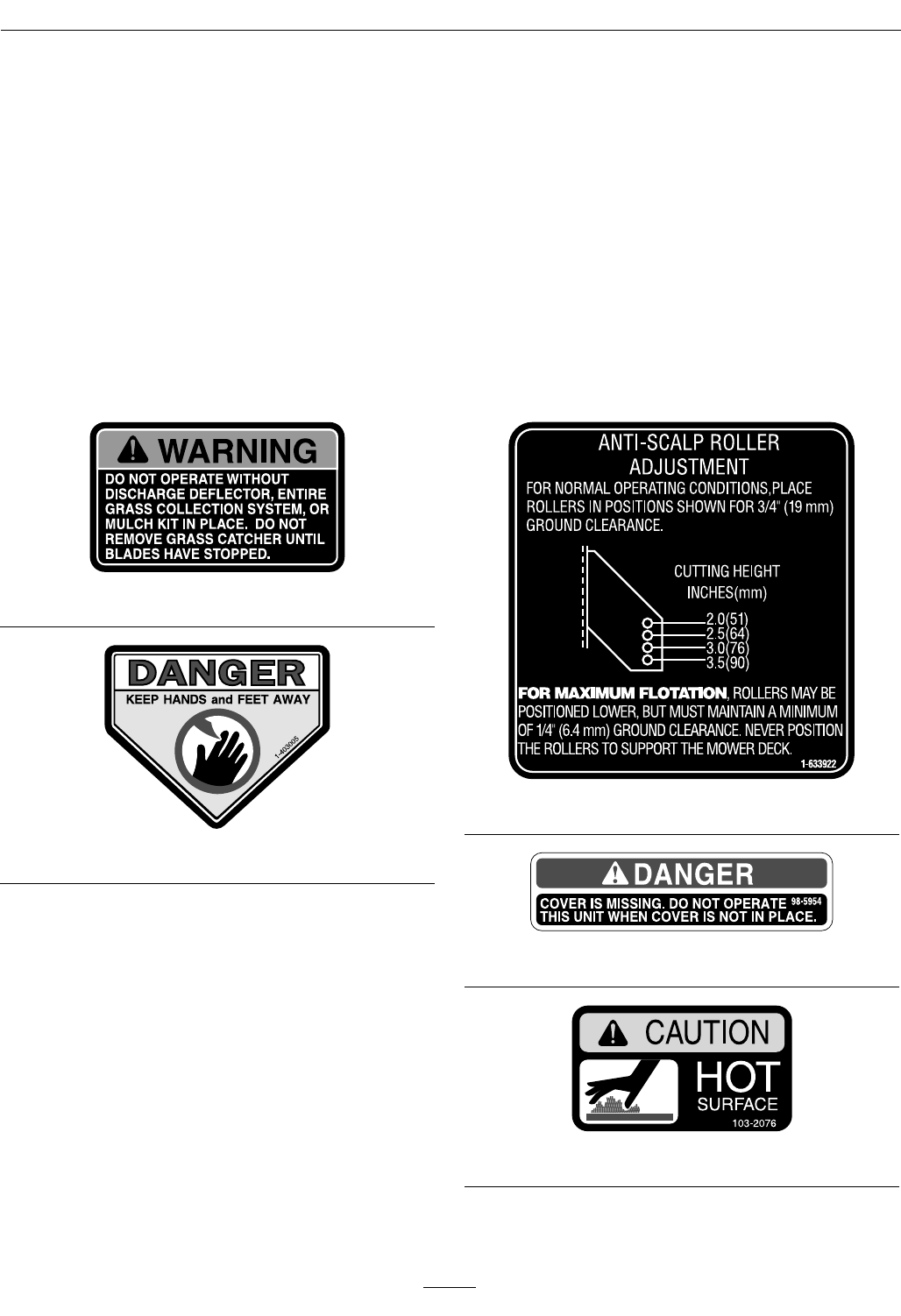
1-303508
1-403005
1-633922
98-5954
103-2076
11
Safety
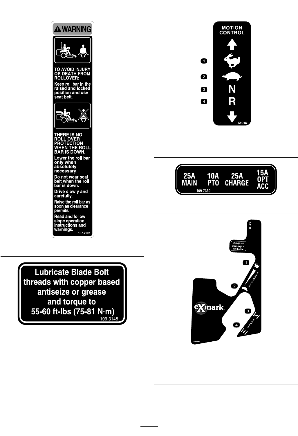
107-2102
109-3148
109-7232
1.Fast3.Neutral
2.Slow4.Reverse
109-7330
109-8483
AllUnitsExceptEFI
1.Throttle–fast3.Choke–on
2.Throttle–slow4.Choke–off
12
Safety
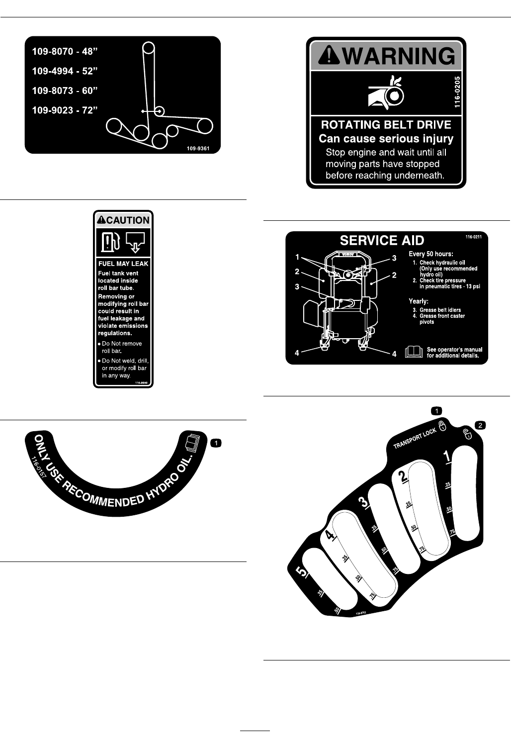
109-9361
DeckDriveBeltRouting
116-0090
116-0157
1.SeeOperator'sManual
116-0205
116-0211
116-0752
1.Latch2.Unlatch
13
Safety
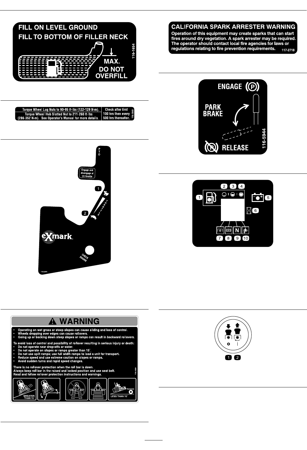
116-1654
116-2643
116-2844
EFIUnitsOnly
1.Throttle–fast2.Throttle–slow
116-3303
117–2718
116-5944
MessageDisplay
1.Fuel6.Hourmeter
2.Empty7.PTO
3.Half8.Parkingbrake
4.Full9.Neutral
5.Battery10.Operatorpresence
switch
PTOSwitchSymbols
1.PTO–disengage2.PTO–engage
14

Safety
109-7069
15

Specications
Specications
ModelNumbers
SerialNos:312,000,000andHigher
LZX680KC486;LZX740KC526;LZX740KC606;LZX740KC606CA;LZX749EKC606;LZX801KA606;
LZX801KA606SS;LZX940KC606;LZX940KC726;LZX980KC606;LZX980KC726
Systems
Engine
•EngineSpecications:SeeyourEngineOwner’s
Manual
•EngineOilType:Exmark4–CyclePremium
EngineOil
•RPM:FullSpeed:3750±50RPM(PTOnot
engaged)Idle:1500+100/-250RPM
FuelSystem
•Capacity:12.0gal.(45.4L)
•TypeofFuel:Regularunleadedgasoline,87
octaneorhigher;containingnomorethan10%
methanolorethanol.
•FuelFilter:
–Kohler:
KohlerP/N2405013
–Kawasaki:
KawasakiP/N49019-7005
–KohlerEFI:
KohlerP/N2505042
•FuelShut-OffValve:
AllUnits:1/4turnincrements(“ON”,“OFF”).
•Fuelleveleightsegmentdisplay—righthand
controlpanel.
•Lowfuelindicatorlight.
ElectricalSystem
•ChargingSystem:FlywheelAlternator
•ChargingCapacity:
KohlerandKawasaki:15amps
KohlerEFI:20amps
•BatteryType:BCIGroupU1
•RecommendedMinimumBatteryCCA:
–Kohler940&980engines:340CCA
–Allotherengines:260CCA
•BatteryVoltage:12Volt
•LowVoltageLight—RHcontrolpanel
•Polarity:NegativeGround
•Fuses:
Allunits:
–25ampmainfuse
–25ampchargingsystemfuse
–10ampPTOfuse
–15ampaccessoryfuse
SafetyInterlockSystem
•LCDindicatorsappearforthePTO,parkbrake,
drivelevers,andoperatorpresenceinthemessage
displayontheRHcontrolpanel.
•PTOmustbedisengaged,brakeengaged,and
motioncontrolleversout(neutrallock)tostart
engine.(Itisnotnecessaryfortheoperatortobe
intheseattostarttheengine.)
•OperatormustbeinseatwhenPTOisengaged,
brakeisdisengaged,ormotioncontrolleversare
movedinorenginewillstop.
•Enginewillstopifeithertheleft,theright,or
bothleversaremovedfromneutrallockposition
whilebrakeisengaged.
OperatorControls
•SteeringandMotionControl:
Note:Motioncontrolleversareadjustableto
twoheights.
–Separatelevers,oneachsideoftheconsole,
controlspeedanddirectionoftravelofthe
respectivedrivewheels.
–Steeringiscontrolledbyvaryingtheposition
oftheleversrelativetoeachother.
16

Specications
–Movingmotioncontrolleversoutward(in
slots)locksthedrivesysteminneutral.
•PTOEngagementSwitch:Engageselectricclutch
(todrivebelt)whichengagesmowerblades.
•ParkingBrakeLever:Engages/Disengages
parkingbrake.
•DeckHeightAdjustmentLever:Setscutting
heighttodesiredposition.
•DeckLiftPedal:Footpedalthatliftsdeck.
•TransportLock:
–Latchingposition:Automaticallylatchesat
thetransportposition.
–Unlatchingposition:Deckdoesnotlatchat
thetransportposition.
Seat
•Type:
–ForallunitsexceptLZX801KA606SS,
LZX940KC606,LZX940KC726,
LZX980KC606,LZX980KC726:Standard
seatwithhighback,extrawidefoampadded
seatcushionwithinternalsuspension,thick
bolstering,two-tonecover,armrests,integral
safetyswitch,andseatvibrationisolation
system.
Optionalseataccessoriesforunitswith
standardseats:
◊Customridesuspensionsystemtoenhance
StandardSeat.Addsapproximately3
inches(7.6cm)toseatheight.
◊Deluxesuspension(adjustablespring
suspension)seatwithhighback,armrests,
andintegralsafetyswitch.Seatheight
remainsthesame.
–ForLZX801KA606SS,LZX940KC606,
LZX940KC726,LZX980KC606,
LZX980KC726:
Deluxesuspension(adjustablespring
suspension)seatwithhighback,armrests,and
integralsafetyswitch.Seatheightremainsthe
same.
•Mounting:Hingedseatframetotiltupseat.Held
intiltedpositionwithproprod.Adjustablefore
andaftonseattracks.
•Armrests:
–Standardseat:foampaddedadjustableip-up
armrests.
–Suspensionseat:moldedadjustableip-up
armrests.
•SeatSafetySwitch:
Integratedseatswitch.Timedelayseatswitch
eliminatesroughgroundcut-outs.
HydrostaticGroundDriveSystem
•Twounitizedhydrostatictransmissions:
–48and52inchdecks:
◊12ccParkeraxialpistonpump
◊240ccParkergerolermotor
–60and72inchdecks:
◊16ccParkeraxialpistonpump
◊280ccRossgerolermotor
•HydraulicOilType:ExmarkPremiumHydroOil.
•HydraulicOilCapacity:52oz(1.5L)perside
•HydraulicFilter:P/N116-0164
•Speeds:
–12cc
◊0-10mph(16.1km/hr)forward.
◊0-5.5mph(8.9km/hr)reverse.
–16cc
◊0-11.5mph(18.5km/hr)forward.
◊0-6mph(9.7km/hr)reverse.
•Drivewheelreleasevalvesallowmachinetobe
movedwhenengineisnotrunning.
17

Specications
Tires&Wheels
DriveFrontCaster
Pneumatic
(Air-Filled)
Semi-Pneumatic
Quantity22
Tread“Multi-TracC/S”Smooth
Size(60&72
Decks)
24x12.00-1213x6.50-6
Size(48&52
Decks)
24x9.50-1213x5.00-6
PlyRating4
Pressure13psi(90kPa)
CuttingDeck
•CuttingWidth:
–48inchDeck:(121.9cm)
–52inchDeck:(132.1cm)
–60inchDeck:(152.4cm)
–72inchDeck:(182.9cm)
•Discharge:Side
•BladeSize:(3ea.)
–48inchDeck:16.25inches(41.3cm)
–52inchDeck:18.00inches(45.7cm)
–60inchDeck:20.50inches(52.1cm)
–72inchDeck:24.50inches(62.2cm)
•BladeSpindles:Solidsteelspindleswith1.18inch
(30mm)I.D.bearings.
•DeckDrive:
Electricclutch.Shaftdiameter1.125inches(2.86
cm)
–48and52inchDecks:“B”Sectionbeltwith
self-tensioningidler.
–60and72inchDecks:5VSectionbeltwith
self-tensioningidler.
•Deck:
Fulloatingdeckisattachedtoout-frontsupport
frame.Anti-scalprollersprovidemaximumturf
protection.Deckdesignallowsforbagging,
mulchingorsidedischarge.
–48inchDeck:3anti-scalprollers
–52inchDeck:3anti-scalprollers
–60inchDeck:4anti-scalprollers
–72inchDeck:6anti-scalprollers
•DeckDepth:
–48inchDeck:5.5inches(14cm)
–52inchDeck:5.5inches(14cm)
–60inchDeck:5.5inches(14cm)
–72inchDeck:5.5inches(14cm)
•CuttingHeightAdjustment:
Footactivatedleverisusedtoadjustthecutting
heightfrom1inch(2.5cm)to51/2inches(14
cm)in1/4inch(6.4mm)increments.
•MulchingKit:Optional.
Dimensions
OverallWidth:
48inchDeck52inchDeck
WithoutDeck45.7inches
(116.1cm)
48.0inches
(122.0cm)
DeectorUp51.8inches
(131.6cm)
56.3inches
(143.0cm)
DeectorDown59.6inches
(151.4cm)
64.8inches
(164.6cm)
60inchDeck72inchDeck
WithoutDeck53.0inches
(134.6cm)
59.1inches
(150.1cm)
DeectorUp62.5inches
(158.8cm)
73.5inches
(186.7cm)
DeectorDown72.8inches
(184.9cm)
84.9inches
(215.6cm)
OverallLength:
48inchDeck52inchDeck
RollBar-Up79.2inches
(201.2cm)
79.2inches
(201.2cm)
RollBar-Down80.9inches
(205.5cm)
80.9inches
(205.5cm)
60inchDeck72inchDeck
RollBar-Up83.1inches
(211.1cm)
86.1inches
(218.7cm)
RollBar-Down84.8inches
(215.4cm)
87.8inches
(223.0cm)
18

Specications
OverallHeight:
RollBar-UpRollBar-Down
70.5inches(179.1cm)46.8inches(118.9cm)
TreadWidth:(CentertoCenterof
Tires,Widthwise)
48inchDeck52inchDeck
DriveWheels36.2inches
(91.9cm)
38.5inches
(97.8cm)
CasterWheels32.8inches
(83.3cm)
32.8inches
(83.3cm)
60inchDeck72inchDeck
DriveWheels41.6inches(105.7
cm)
43.6inches(110.7
cm)
CasterWheels39.5inches(100.3
cm)
47.1inches(119.6
cm)
WheelBase:(CenterofCasterTireto
CenterofDriveTire)
48inch
Deck
52inch
Deck
60inch
Deck
72inch
Deck
48.0inches
(121.9cm)
48.0inches
(121.9cm)
51.6inches
(131.1cm)
53.6inches
(136.1cm)
CurbWeight:
48inch
Deck
52inch
Deck
60inch
Deck
72inch
Deck
Kohler
680Units
1125lb
(510kg)
———
Kohler
740Units
—1116lb
(506kg)
1195lb
(542kg)
—
Kohler
749Units
——1195lb
(542kg)
—
Kawasaki
801Units
——1212lb
(550kg)
—
Kohler
940Units
——1244lb
(564kg)
1276lb
(579kg)
Kohler
980Units
——1244lb
(564kg)
1276lb
(579kg)
AccessoryWeightTableWorksheet:
Usethetablebelowtodetermineifextraweight
isrequiredfortheunit.Identifytheaccessories
andcorrectdecksizeandplacethecorresponding
valuesintheAccessoryScorecolumn.IftheTotal
AccessoryScoremeetsthefollowing,addthe
recommendedweightkit.
Note:The72inchdeckdoesnotrequireaweightkit.
48inch
Deck
52inch
Deck
60inch
Deck
Accessory
Score
LightKit232
Michigan
Seat/CRSS
11123
Bagger003
Pneumatic
CasterTires
685
MulchKit-3-4-5
StriperKit-200
OCD02-5-7-4
HitchKit121
Sunshade
Kit
232
TotalAccessoryScore
TotalAccessoryScoreRequiredWeightKit(s)
0–9Nonerequired
10–19*116-1173Undertoeboard
mountweightkit
20andHigher*Two116-1173Undertoe
boardmountweightkitsor
one116-1173Undertoe
boardmountweightkit
andone116-1238Front
toeboardmountweightkit
*48inchunitsthatcomewithanundertoeboard
weightasstandard,canaddanadditionaltoeboard
weightforprimaryaccessoryweighting(scores
10-19);andfronttoeboardweightkitforsecondary
accessoryweighting(scores20andhigher).Other
unitsshouldinstallarstundertoeboardkitfor
primaryaccessoryweighting(scores10-19);anda
secondundertoeboardkitforsecondaryaccessory
weighting(scores20andhigher).
19
ProductOverview
*60inchunitswhichalreadyhaveanundertoeboard
mountweightasstandardrequires116-1238fronttoe
boardtopmountkitinsteadof116-1173.
TorqueRequirements
BoltLocationTorque
BladeDriveSheave
MountingNut
90-110ft-lb(122-149N-m)
CutterHousingSpindle
Nut
160-185ft-lb
(217-251N-m)
BladeMountingBolt
(lubricatewithanti-seize)
55-60ft-lb(75-81N-m)
Anti-ScalpRollerNyloc
NutSeeFigure18
30-35ft-lb(41-47N-m)
Anti-ScalpRollerHex
CapscrewSeeFigure18
50-55ft-lb(68-75N-m)
EngineMountingBolts
(Kohler680&740)
(Kohler749)
(Kohler940)
(Kohler980)
(Kawasaki801)
27-33ft-lb(37-45N-m)
27-33ft-lb(37-45N-m)
17-21ft-lb(23-28N-m)
17-21ft-lb(23-28N-m)
27-33ft-lb(37-45N-m)
WheelLugNuts90-95ft-lb(122-129N-m)
WheelMotorMounting
Bolts
72-77ft-lb(98-104N-m)
WheelHubSlottedNut211-260ft-lb
(286-352N-m)
RolloverProtection
System(RollBar)1/2
inchMountingBolts
75-80ft-lb(102-108N-m)
ClutchRetainingBolt
(securedwiththreadlocker)
55-60ft-lb(75-81N-m)
HydroParkBrake
CableAnchor1/2inch
MountingBolt(secured
withthreadlocker)
67-89ft-lb(91-121N-m)
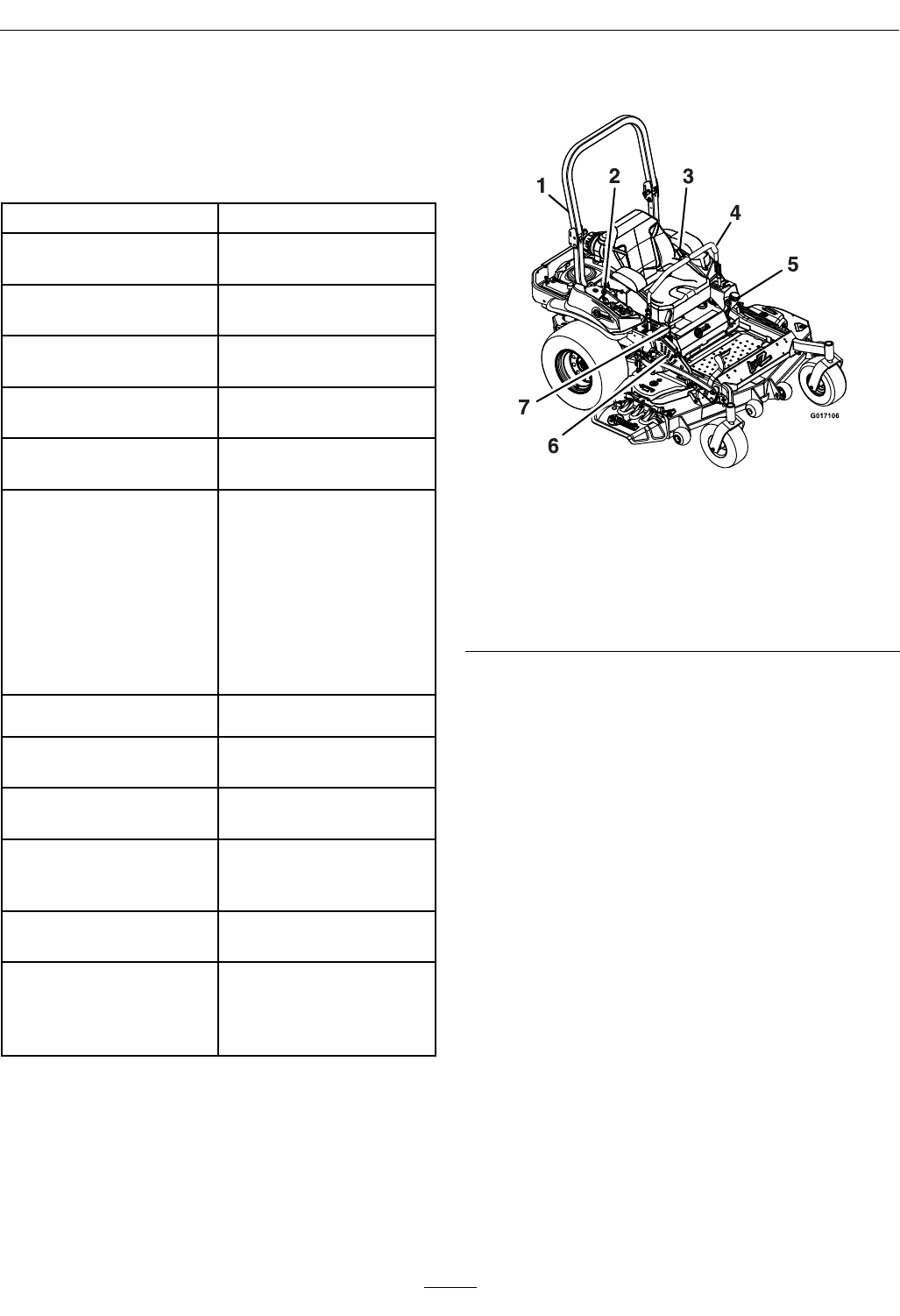
ProductOverview
Figure4
1.RolloverProtection
System(ROPS)
5.Fuelcap
2.EngineControls(right
console)
6.Heightofcutadjustment
3.Seatbelt7.Parkingbrake
4.Motioncontrollevers
20
Operation
Operation
Note:Determinetheleftandrightsidesofthe
machinefromthenormaloperatingposition.
Controls
MotionControlLevers
Themotioncontrolleverslocatedoneachsideof
theconsolecontroltheforwardandreversemotion
ofthemachine.
Movingtheleversforwardorbackwardturns
thewheelonthesamesideforwardorreverse
respectively.Wheelspeedisproportionaltothe
amounttheleverismoved.
Movingtheleversoutwardfromthecenterposition
intotheT-slotlocksthemintheneutralposition
(Figure5).
Whenthemotioncontrolleversareintheneutral
position,theLCDindicatorappearsinthemessage
displayontheRHconsole(seeFigure8).
Figure5
1.Neutrallockposition
(handlesout)
4.Forward
2.Neutraloperateposition
(handlesin)
5.Neutral(operate)
3.FrontofUnit6.Reverse
ChokeControl(AllUnitsExcept
KohlerEFI)
Locatedonrightconsole(blacklever)(seeFigure6).
Thechokeisusedtoaidinstartingacoldengine.
Movingthechokeleverforwardwillputthechokein
the“ON”positionandmovingthechokelevertothe
rear,tothedetent,willputthechokeinthe“OFF”
position.DoNotrunawarmenginewithchokein
the“ON”position.
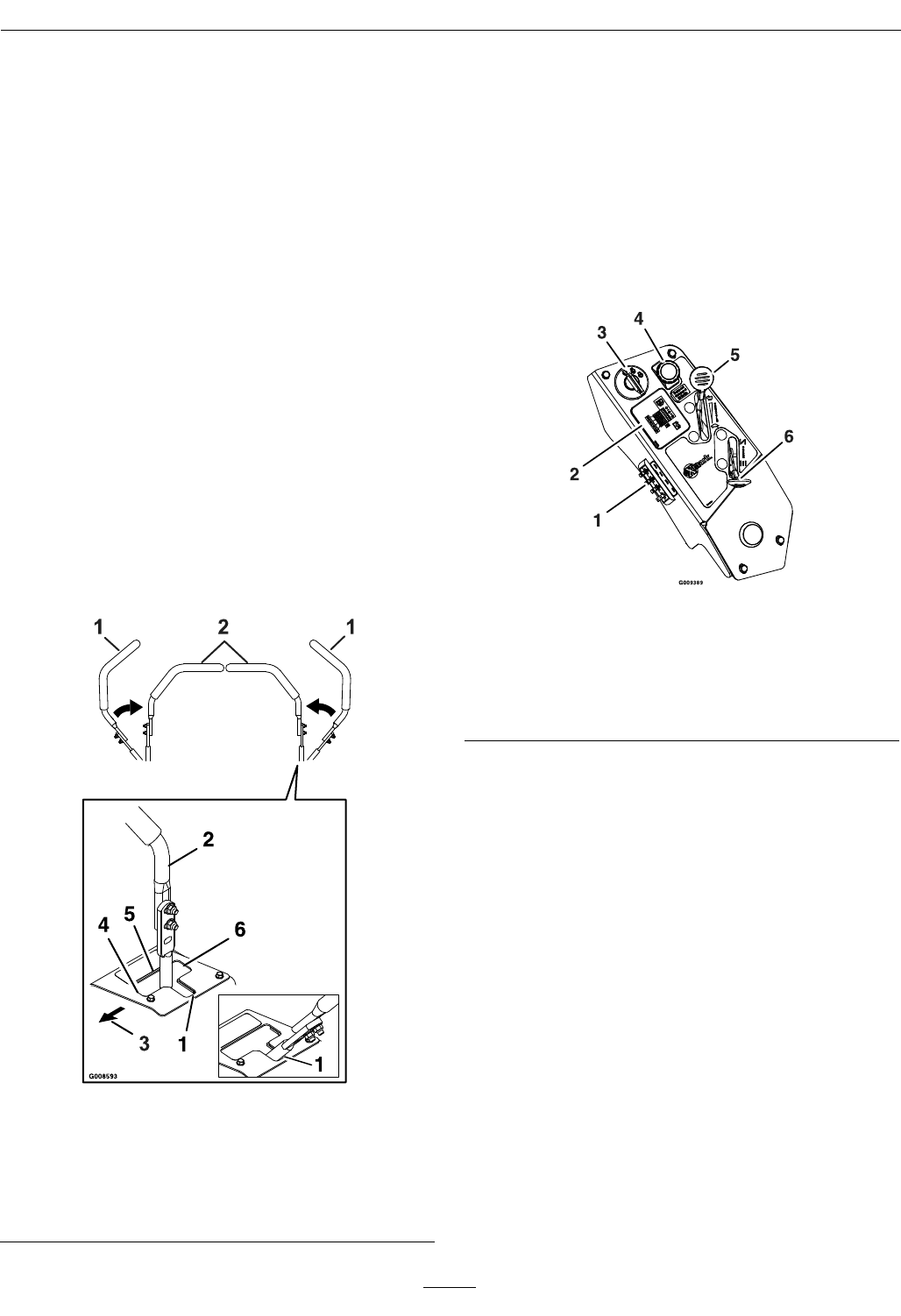
Figure6
RightConsole
1.Fuses4.PTOengagementswitch
2.Messagedisplay5.Throttle
3.Ignitionswitch6.Choke
ThrottleControl
Locatedonrightconsole(redlever)(seeFigure6).
Thethrottleisusedtocontrolenginespeed.Moving
thethrottleleverforwardwillincreaseenginespeed
andmovingthethrottlelevertotherearwilldecrease
enginespeed.Movingthethrottleforwardintothe
detentisfullthrottle.
BrakeLever
Locatedonrightsideofunit,justtothefrontofthe
RHmotioncontrollever.
Thebrakeleverengagesaparkingbrakeonthedrive
wheels.
Note:TheLCDindicatorappearsinthemessage
displayontheRHconsolewhentheparkbrakeis
engaged(seeFigure8).
Pulltheleverupandrearwardtoengagethebrake.
21
Operation
Pushtheleverforwardanddowntodisengagethe
brake.
Theunitmustbetieddownandbrakeengagedwhen
transporting.
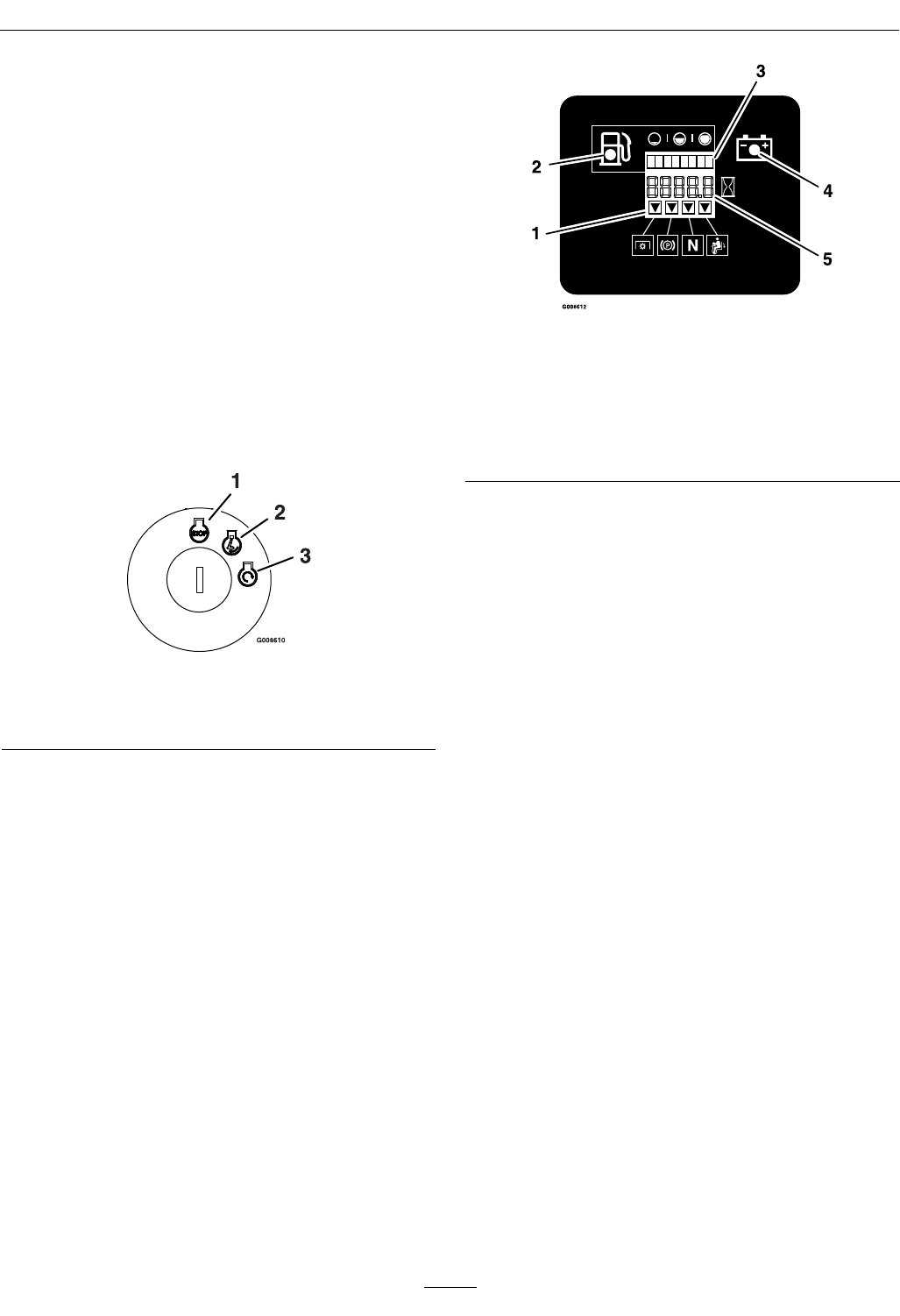
IgnitionSwitch
Locatedonrightconsole(seeFigure6).
Theignitionswitchisusedtostartandstopthe
engine.Theswitchhasthreepositions“OFF”,“ON”
and“START”.Insertkeyintoswitchandrotate
clockwisetothe“ON”position.Rotateclockwiseto
thenextpositiontoengagethestarter(keymustbe
heldagainstspringpressureinthisposition).Allow
thekeytoreturntothe“on”positionimmediately
aftertheenginestarts.
Figure7
1.Off3.Start
2.On
Note:Brakemustbeengaged,motioncontrol
leversout(neutrallockposition)andPTOswitch
disengagedtostartengine.(Itisnotnecessaryforthe
operatortobeintheseattostarttheengine.)
HourMeter
Locatedontherightconsoleinthemessagedisplay
(seeFigure6andFigure8).
Thehourmeterrecordsthenumberofhoursthat
theenginehasrun.
Figure8
1.LCDIndicators
2.Lowfuelindicatorlight
3.Fuellevelbardisplay
4.Lowvoltageindicatorlight
5.Hour/Voltagedisplay
Thehourmeterisrecordingwhenthedecimalpoint
isashinginHour/Voltagedisplay.
Hoursaredisplayedwhenthekeyisofforwhenthe
machineisrunning.
Note:Iftheignitionkeyisturnedtothe“ON”
positionforafewsecondsbeforecrankingtheengine,
thebatteryvoltagewilldisplayintheareawherethe
hoursarenormallydisplayed.
Note:TheLCDindicatorsappearwheneachcontrol
meetsthe“safetostart”mode(e.g.theindicator
turnsonwhentheoperatorisintheseat.)
FuelShut-OffValve
Locatedbehindandbelowtheseat.
Thefuelshut-offvalveisusedtoshutoffthefuel
whenthemachinewillnotbeusedforafewdays,
duringtransporttoandfromthejobsite,andwhen
parkedinsideabuilding.
Alignvalvehandlewiththefuellinetoopen.Rotate
90°toclose.
FuelGauge
Locatedontherightconsoleinthemessagedisplay
(seeFigure6andFigure8).
Thefuellevelisshownonabardisplay.Theindicator
lightappearswhenthefuellevelislow(approximately
onegallonremaininginthetank).
22
Operation
DriveWheelReleaseValves
WARNING
Handsmaybecomeentangledintherotating
drivecomponentsbelowtheenginedeck,which
couldresultinseriousinjuryordeath.
Stopengine,removekey,allowallthemoving
partstostopbeforeaccessingthedrivewheel
releasevalves.
WARNING
Theengineandhydraulicdriveunitscanbecome
veryhot.Touchingahotengineorhydraulic
driveunitscancausesevereburns.
Allowtheengineandhydraulicdriveunitsto
coolcompletelybeforeaccessingthedrivewheel
releasevalves.
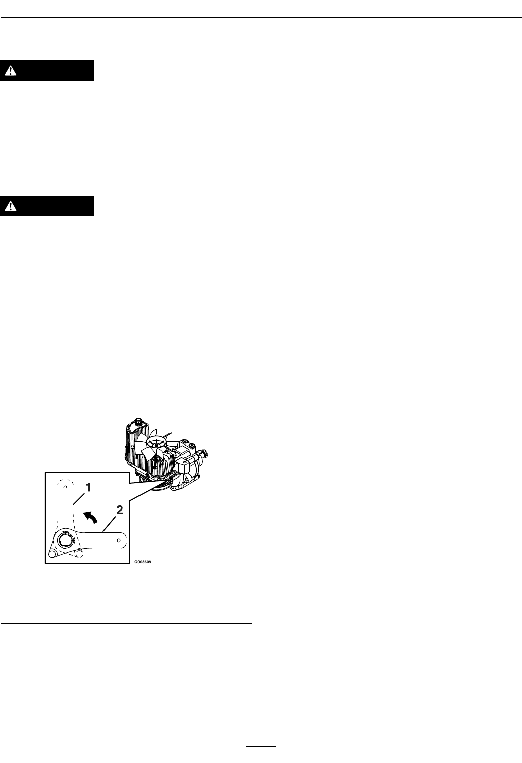
Locatedonthebackoftheunitizedhydraulicdrive
units,belowtheenginedeck.
Duringnormaloperatingconditions,thedrivewheel
releasevalvesarepositionedhorizontally.Ifthe
machinehastobepushedbyhand,thevalvesmust
beinthe“released”position(seeFigure9).
Figure9
1.Handlein“released”position
2.Handlein“operating”position
Toreleasethedrivesystem(seeitem1inFigure9),
rotatethehandle1/4turntotheverticalposition
untilithitsagainstthestop.
Toresetthedrivesystem(seeitem2inFigure9),
rotatethehandle1/4turntothehorizontalposition
untilithitsagainstthestop.
Note:Thehandlemustbehorizontalandagainst
thestopforoperation.
DoNottowmachine.
PTOEngagementSwitch
Locatedonrightconsole(seeFigure6).
Switchmustbepulledout(up)toengagetheblades.
Switchispushedintodisengagetheblades.
TheLCDindicatorwillappearwhenthePTOswitch
isdisengaged(seeFigure8).
LowVoltageIndicator
Locatedontherightconsoleinthemessagedisplay
(seeFigure6andFigure8).
Alowvoltagecondition(lessthan12.3volts)exists
whentheLCDindicatorappearsonthemessage
displaywhiletheengineisrunning.
Iftheignitionkeyisturnedtothe“ON”positionfor
afewsecondsbeforecrankingtheengine,thebattery
voltagewilldisplayintheareawherethehoursare
normallydisplayed.
Note:Theindicatornormallyappearswhenthe
engineisoffandthekeyswitchisturnedtothe
“ON”position.
DeckLiftPedal
Locatedattherightfrontcorneroftheoorpan.
Pushthepedalforwardwithyourfoottoraisethe
cuttingdeck.Allowthepedaltomoverearwardto
lowerthecuttingdecktothecutheightthathasbeen
set.
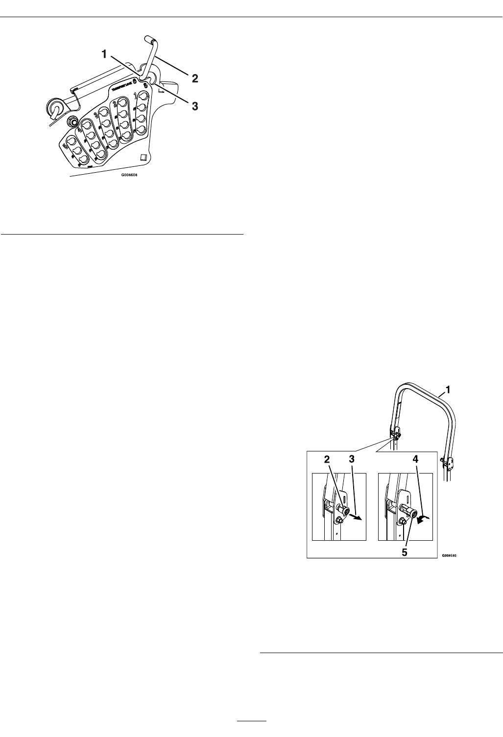
TransportLock
Locatedontheheightofcutadjustmentplatestothe
rightoftheparkingbrake.
Positioninthetransportlatchingpositionto
automaticallylatchthecuttingdeckwhenraisedto
thetransportposition(seeitem1inFigure10).
Inthenon-latchingposition,thedeckwill
automaticallyreturntothecuttingheightwhenthe
pedalislowered(seeitem3inFigure10).
23
Operation
Figure10
1.Latchingposition3.Non-latchingposition
2.Transportlockcontrol
ElectronicControlUnitMalfunction
Indicator
KohlerEFIUnitsOnly:
Theelectroniccontrolunit(ECU)continuously
monitorsoperationoftheEFIsystem.Ifaproblem
orfaultwithinthesystemisdetected,themalfunction
indicatorlight(MIL)isilluminated.TheMIListhe
lightlocatedintherightconsolepaneltotherightof
thethrottlecontrol.Followthetroubleshootingsteps
outlinedintheKohlerengineoperator’smanualifthe
MILisilluminated.
Pre-Start
Fillfueltankonlevelground.Forbestresultsuse
onlyclean,freshregulargradeunleadedgasolinewith
anoctaneratingof87orhigher.
Important:Neverusemethanol,gasoline
containingmethanol,gasoholcontainingmore
than10%ethanol,premiumgasoline,orwhite
gasbecausethefuelsystemcouldbedamaged.
DoNotaddoiltogasoline.
DoNotoverllfueltank.Fillthefueltanktothe
bottomofthellerneck.Theemptyspaceinthe
tankallowsgasolinetoexpand.Overllingmayresult
infuelleakageordamagetotheengineoremission
system.
Makesureyouunderstandthecontrols,their
locations,theirfunctions,andtheirsafety
requirements.
RefertotheMaintenancesectionandperformallthe
necessaryinspectionandmaintenancesteps.
OperatingInstructions
RaisetheRolloverProtectionSystem
(ROPS)
Important:Therollbarisanintegraland
effectivesafetydevice.Keeptherollbarinthe
raisedandlockedpositionwhenoperatingthe
mower.Lowertherollbartemporarilyonlywhen
absolutelynecessary.
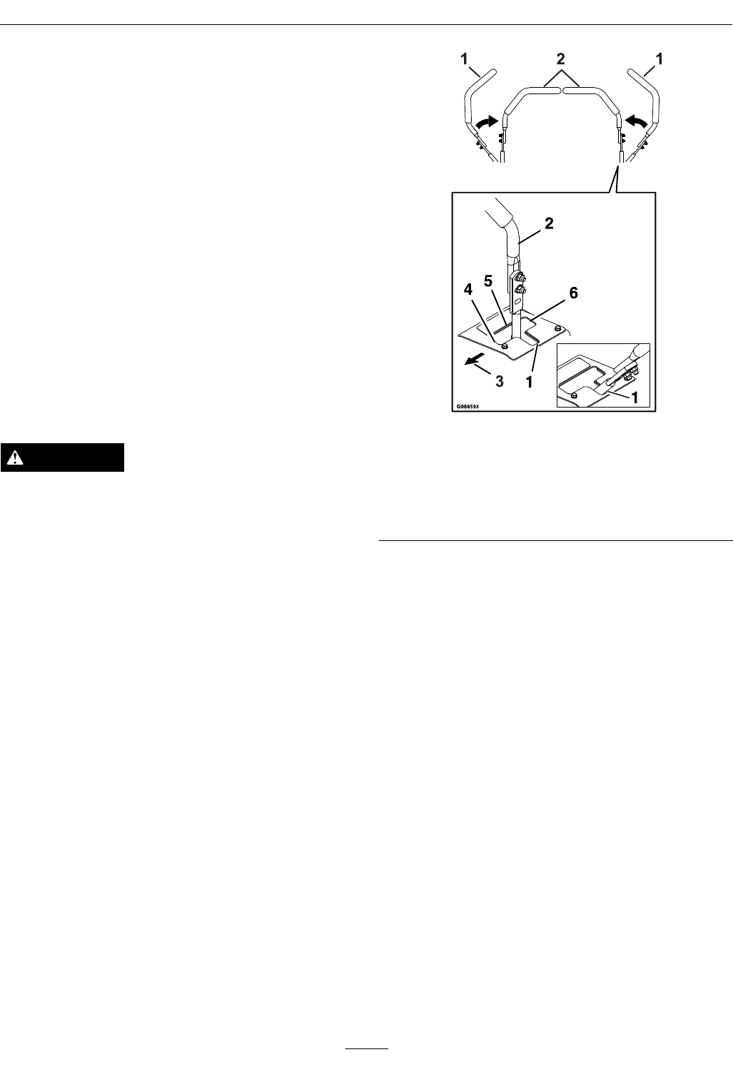
1.Theknobmustbecompletelylatchedwiththe
tabsinterlockingasshowninFigure11tolock
therollbarintheraised,operateposition.
2.Applyforwardpressuretotheupperhoopofthe
rollbar.
3.Pulltheknobandrotate90°toholdinthe
unlatchedpositiontolowertherollbar.
4.Toreturntotheoperateposition,raisetheroll
bar,andthenrotateknobs90°sothatthetabs
interlockpartially.Applyforwardpressuretothe
rollbarupperhoopandobservethattheknobs
returntothecompletelylatchedposition.
Figure11
1.Rollbarupperhoop
2.Knobin“latched”position
3.Pullknobtounlatch
4.Rotate90°toholdunlatched
5.Knobin“unlatched”position
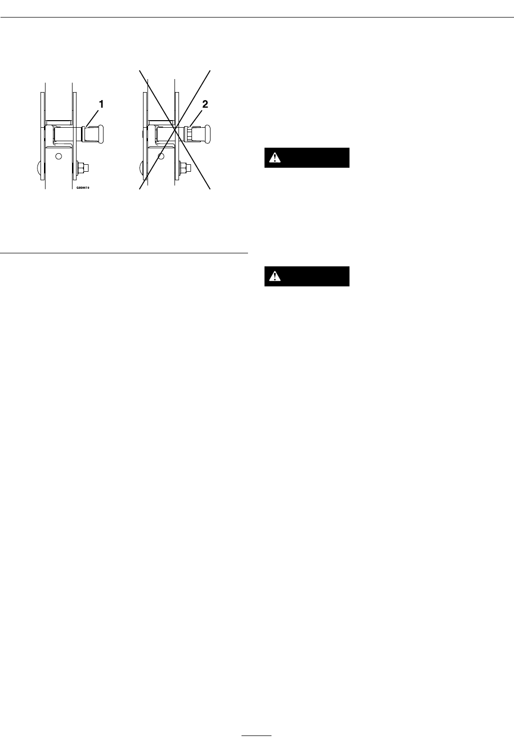
5.Makesuretheknobsarefullyengagedwiththe
rollbarintheraisedposition.Theupperhoopof
therollbarmayneedtobepushedforwardor
24
Operation
pulledrearwardtogetbothknobsfullyengaged
(seeFigure12).
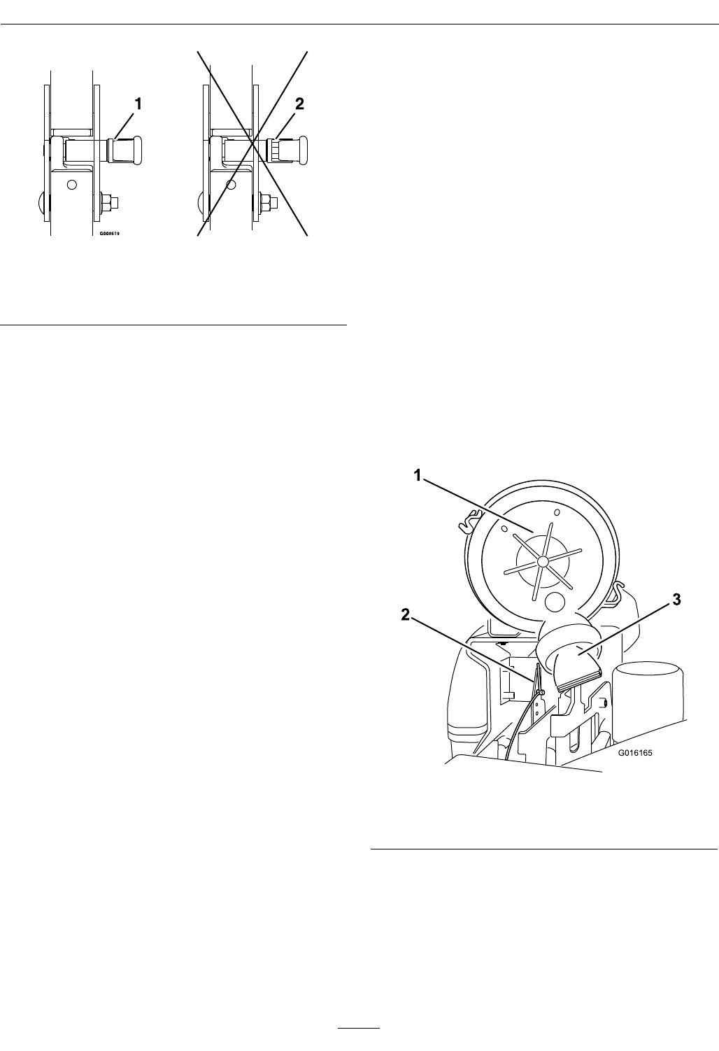
Figure12
1.Engaged2.Partiallyengaged—Do
NotoperatewithROPS
inthiscondition.
Important:Alwaysusetheseatbeltwiththe
rollbarintheoperate(raised)position.Ensure
thattherearpartoftheseatissecuredwiththe
seatlatch.
OpentheFuelShut-OffValve
Rotatethevalveandalignwiththefuellinetoopen.
StartingtheEngine
1.Movethemotioncontrolleversouttotheneutral
lockposition.
2.Pullupandbackontheparkingbrakeleverto
engagetheparkingbrake.
3.PushdownonthePTOswitchtothe“disengage”
position.
Note:Itisnotnecessaryfortheoperatortobe
intheseattostarttheengine.
4.Placethethrottlemidwaybetweenthe“SLOW”
and“FAST”positions.
5.Onacoldengine,pushthechokeleverforward
intothe“ON”position(exceptKohlerEFIunits).
Onawarmengine,leavethechokeinthe“OFF”
position.
6.Turnignitionswitchtothe“START”position.
Releasetheswitchassoonastheenginestarts.
Important:DoNotcranktheengine
continuouslyformorethantensecondsata
time.Iftheenginedoesnotstart,allowa60
secondcool-downperiodbetweenstarting
attempts.Failuretofollowtheseguidelines
canburnoutthestartermotor.
7.Ifthechokeisinthe“ON”position,gradually
returnchoketothe“OFF”positionastheengine
warmsup.
EngagingthePTO
DANGER
Therotatingbladesunderthemowerdeckare
dangerous.Bladecontactcancauseserious
injuryorkillyou.
DoNotputhandsorfeetunderthemoweror
mowerdeckwhenthebladesareengaged.
DANGER
Anuncovereddischargeopeningwillallow
objectstobethrowninanoperator’sor
bystander’sdirection.Also,contactwiththe
bladecouldoccur.Thrownobjectsorblade
contactcancauseseriousinjuryordeath.
Neveroperatethemowerwiththedischarge
deectorraised,removed,oralteredunlessthere
isagrasscollectionsystemormulchkitinplace
andworkingproperly.
ThePTOpush-pullswitchengagesthecuttingblades.
Besurethatallpersonsareclearofthemowerdeck
anddischargeareabeforeengagingPTO.
Important:Operatormustbeinseatbeforethe
PTOcanbeengaged.
1.Setthethrottlemidwaybetweenthe“SLOW”and
“FAST”positions.
2.PullthePTOswitchoutwardtoengagetheblades.
3.Placethethrottleinthe“FAST”positiontobegin
mowing.
DisengagingthePTO
1.Setthethrottlemidwaybetweenthe“SLOW”and
“FAST”positions.
2.PushthePTOswitchintodisengagetheblades.
StoppingtheEngine
1.Bringtheunittoafullstop.
25
Operation
2.Movethemotioncontrolleversouttotheneutral
lockposition.
3.Engagetheparkingbrake.
4.Placethethrottlemidwaybetweenthe“SLOW”
and“FAST”positions.
5.DisengagethePTO.
6.Allowtheenginetorunforaminimumof15
seconds,thenturntheignitionswitchtothe
“OFF”positiontostoptheengine.
7.Removethekeytopreventchildrenorother
unauthorizedpersonsfromstartingengine.
8.Closethefuelshut-offvalvewhenthemachine
willnotbeinuseforafewdays,when
transporting,orwhentheunitisparkedinside
abuilding.
DrivingtheMachine
CAUTION
Machinecanspinveryrapidlybypositioningone
levertoomuchaheadoftheother.Operatormay
losecontrolofthemachine,whichmaycause
damagetothemachineorinjury.
•Usecautionwhenmakingturns.
•Slowthemachinedownbeforemakingsharp
turns.
Important:Tobeginmovement(forwardor
backward)theoperatormustbeintheseat,the
brakelevermustbedisengaged(pusheddown)
beforethemotioncontrolleverscanbemovedin
ortheenginewillstop.
Whenthemotioncontrolleversarepositionedfully
outward(apart)intheT-slot,thedrivesystemisin
theneutrallockposition(Figure13).
Note:The“N”LCDindicatorappearswhenboth
leversareintheneutrallockposition.
Whenthemotioncontrolleversaremoveddirectly
inward(together)thedrivesystemisintheneutral
operateposition.
Figure13
1.Neutrallockposition
(handlesout)
4.Forward
2.Neutraloperateposition
(handlesin)
5.Neutral(operate)
3.FrontofUnit6.Reverse
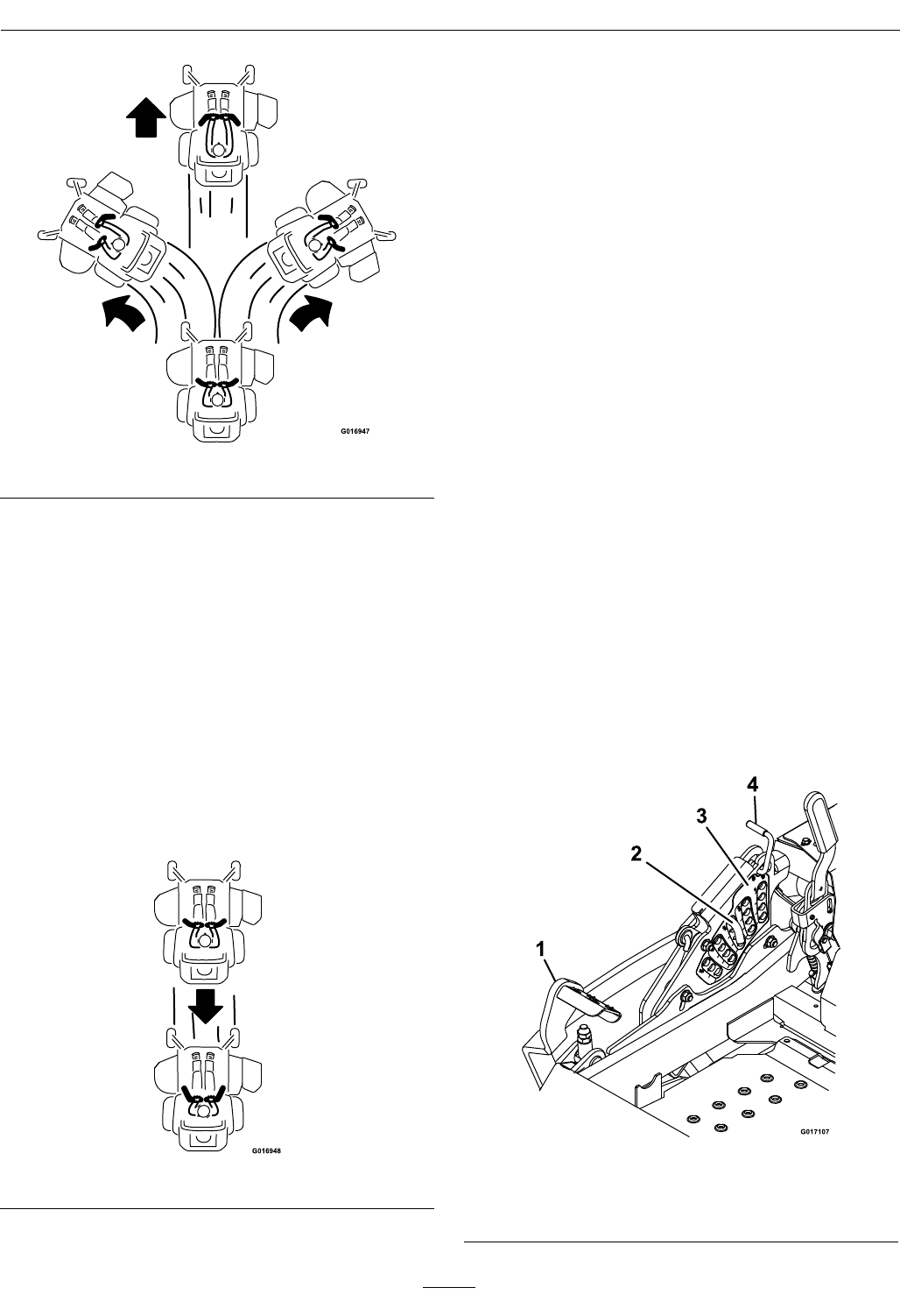
DrivingForward
1.Releasetheparkingbrake.
2.Movethemotioncontrolleversinwardtothe
centertotheneutralposition.
3.Tomoveforwardinastraightline,moveboth
leversforwardwithequalpressure.
26
Operation
Figure14
Toturnleftorright,pullthemotioncontrollever
backtowardneutralinthedesiredturndirection.
Themachinewillmovefasterthefartherthe
motioncontrolleversaremovedfromtheneutral
position.
4.Tostop,positionbothmotioncontrolleversin
theneutraloperateposition.
DrivinginReverse
1.Movethemotioncontrolleversinwardtothe
neutraloperateposition.
2.Tomoverearwardinastraightline,moveboth
leversrearwardwithequalpressure.
Figure15
Toturnright,releasepressureontheRHmotion
controlleverandtherearofthemachinewill
movetowardstherearandtotheright.
Toturnleft,releasepressureontheLHmotion
controlleverandtherearofthemachinewill
movetowardstherearandtotheleft.
3.Tostop,positionbothmotioncontrolleversin
theneutraloperateposition.
AdjustingtheCuttingHeight
Thecuttingheightofthemowerdeckisadjusted
from1to51/2inches(2.5cmto14cm)in1/4inch
(6.4mm)increments.
1.Stopthemachineandmovethemotioncontrol
leversoutwardtotheneutrallockedposition.
2.DisengagethePTO.
3.Positionthetransportlockinthelatching
position.
4.Raiseandlockthedecktothe51/2inch(14cm)
transportposition(Figure16).
Thedeckisraisedbypushingthefootoperated
deckliftpedalforward.Thepedalislocatedatthe
frontrightcorneroftheoorpan.
Note:Whenchangingthecuttingheight
positions,alwayscometoacompletestop
anddisengagethePTO.
Figure16
1.Deckfootpedal3.Heightofcutdecal
2.Heightadjustmentpin4.Transportlockcontrol
27
Operation
5.Inserttheheightadjustmentpinintothehole
correspondingtothedesiredcuttingheight.
Seethedecalonthesideofthedeckliftplatefor
cutheights.
6.Pushthedeckliftpedal,releasethetransportlock
andallowthedecktolowertothecuttingheight.
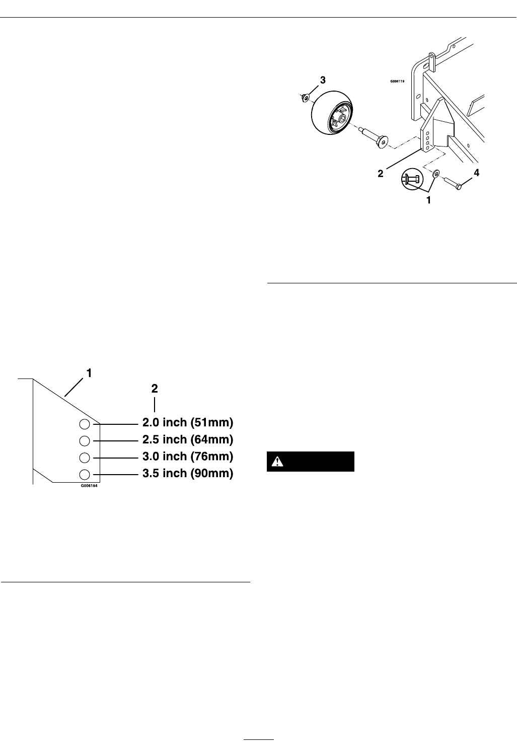
AdjustingtheAnti-ScalpRollers
Itisrecommendedtochangetheanti-scalproller
position,whentheheightofcuthaschanged.
1.Stopthemachineandmovethemotioncontrol
leversoutwardtotheneutrallockposition.
2.DisengagethePTO.
3.Engagetheparkbrake.
4.Stoptheengine,removethekeyandwaitforall
movingpartstostop.
5.Adjusttheanti-scalprollersbyremovingthe
bushing,springdiscwasherandbolt.
6.Placetherollersinoneofthepositionsshown
(Figure17).Rollerswillmaintain3/4inch(19
mm)clearancetothegroundtominimizegouging
androllerwearordamage.
Figure17
Forcuttingheightsabove3.5inches(90mm)usethe
bottomhole.Therollerswillstillbeeffectiveagainst
scalping.
1.Anti-scalproller
mountingbracket
2.Cuttingheight
ForMaximumDeckFlotation,placetherollers
oneholepositionlower.Rollersshouldmaintain
1/4inch(6.4mm)clearancetotheground.Do
Notadjusttherollerstosupportthedeck.
7.Besuretherollerboltsareinstalledwiththe
springdiscwasherbetweentheheadofthebolt
andthemountingbracket(Figure18).
8.Torquethe3/8–24x2Gr8hexcapscrewto
50–55ft-lb(68–75N-m)(Figure18).
Figure18
1.Springdiscwasher
(conetowardsbolthead)
3.3/8nyloc-torqueto30-35
ft-lb(41-47N-m)
2.Frontrightanti-scalp
bracketshown
4.3/8-24x2GR8torqueto
50-55ft-lb(68-75N-m)
Transporting
TransportingaUnit
Useaheavy-dutytrailerortrucktotransportthe
machine.Lockbrakeandblockwheels.Securely
fastenthemachinetothetrailerortruckwithstraps,
chains,cable,orropes.Besurethatthetrailerortruck
hasallnecessarylightingandmarkingasrequiredby
law .Secureatrailerwithasafetychain.
CAUTION
Thisunitdoesnothaveproperturnsignals,
lights,reectivemarkings,oraslowmoving
vehicleemblem.Drivingonastreetorroadway
withoutsuchequipmentisdangerousand
canleadtoaccidentscausingpersonalinjury.
Drivingonastreetorroadwaywithoutsuch
equipmentmayalsobeaviolationofStatelaws
andtheoperatormaybesubjecttotrafctickets
and/ornes.
DoNotdriveaunitonapublicstreetorroadway.
28

Operation
WARNING
Loadingaunitonatrailerortruckincreases
thepossibilityofbackwardtip-over.Backward
tip-overcouldcauseseriousinjuryordeath.
•Useextremecautionwhenoperatingaunit
onaramp.
•Useonlyasingle,fullwidthramp;DoNot
useindividualrampsforeachsideoftheunit.
•Ifindividualrampsmustbeused,useenough
rampstocreateanunbrokenrampsurface
widerthantheunit.
•DoNotexceeda15°anglebetweenrampand
groundorbetweenrampandtrailerortruck.
•Avoidsuddenaccelerationwhiledrivingunit
uparamptoavoidtippingbackward.
•Avoidsuddendecelerationwhilebackingunit
downaramptoavoidtippingbackward.
LoadingaUnit
Useextremecautionwhenloadingunitsontrailersor
trucks.Onefullwidthrampthatiswideenoughto
extendbeyondthereartiresisrecommendedinstead
ofindividualrampsforeachsideoftheunit.The
lowerrearsectionofthetractorframeextendsback
betweentherearwheelsandservesasastopfor
tippingbackward.Havingafullwidthrampprovides
asurfacefortheframememberstocontactifthe
unitstartstotipbackward.Ifitisnotpossibletouse
onefullwidthramp,useenoughindividualrampsto
simulateafullwidthcontinuousramp.
Rampshouldbelongenoughsothattheangles
betweentherampandthegroundandtherampand
thetrailerortruckDoNotexceed15°.Asteeper
anglemaycausemowerdeckcomponentstoget
caughtastheunitmovesfromramptotraileror
truck.Steeperanglesmayalsocausetheunittotip
backward.Ifloadingonornearaslope,position
thetrailerortrucksoitisonthedownsideofthe
slopeandtherampextendsuptheslope.Thiswill
minimizetherampangle.Thetrailerortruckshould
beaslevelaspossible.
Important:DoNotattempttoturntheunit
whileontheramp,youmaylosecontroland
driveofftheside.
Avoidsuddenaccelerationwhendrivinguparamp
andsuddendecelerationwhenbackingdownaramp.
Bothmaneuverscancausetheunittotipbackward.
29

Maintenance
Maintenance
Note:Determinetheleftandrightsidesofthemachinefromthenormaloperatingposition.
WARNING
Whilemaintenanceoradjustmentsarebeing
made,someonecouldstarttheengine.
Accidentalstartingoftheenginecouldseriously
injureyouorotherbystanders.
Removethekeyfromtheignitionswitch,engage
parkingbrake,andpullthewire(s)offthespark
plug(s)beforeyoudoanymaintenance.Also
pushthewire(s)asidesoitdoesnotaccidentally
contactthesparkplug(s).
WARNING
Theenginecanbecomeveryhot.Touchingahot
enginecancausesevereburns.
Allowtheenginetocoolcompletelybefore
serviceormakingrepairsaroundtheenginearea.
RecommendedMaintenanceSchedule(s)
MaintenanceService
IntervalMaintenanceProcedure
Aftertherst5hours•Changetheengineoil.
Aftertherst100hours
•Checkthewheelhubslottednuttorquespecications.
•Checkthewheellugnuts.
•Checktheparkbrakeadjustment.
Aftertherst250hours•Changethehydrauliclteranduid.
Beforeeachuseordaily
•Checktheengineoillevel.
•Checkthemowerblades.
•Checkthesafetyinterlocksystem.
•Checktherolloverprotectionssystems(rollbar)knobs.
•Checktheseatbelt.
•Checkforloosehardware.
•Cleantheengineandexhaustsystemarea.
•Cleanthehydrofancoolingguards.
•Cleanthegrassanddebrisbuild-upfromthemachineandcuttingdeck.
•Cleanthegrassbuild-upfromunderthecuttingdeck.
Every50hours
•Checkthehydraulicoillevel.
•Checkthetirepressures.
•Checktheconditionofthebelts.
•Checksparkarrester(ifequipped).
Every100hours
•Changetheengineoil.(Mayneedmoreoftenundersevereconditions.)
•Lubricatethedeckliftpivots.
•Removetheengineshroudsandcleanthecoolingns.
Every200hours•Checkthesparkplugs.
Every250hours
•Replacetheprimaryaircleanerelement—checksecondaryaircleanerelement;replaceif
dirty.(Mayneedmoreoftenundersevereconditions.SeetheEngineOwner'sManualfor
additionalinformation.)
30

Maintenance
MaintenanceService
IntervalMaintenanceProcedure
Every500hours
•Replacethesecondaryaircleanerelement(Mayneedmoreoftenundersevereconditions.
SeetheEngineOwner'sManualforadditionalinformation.)
•Changethehydrauliclteranduid.(Mayneedmoreoftenundersevereconditions.)
•Checkthewheelhubslottednuttorquespecications.
•Checkthewheellugnuts.
•Checktheparkbrakeadjustment.
Yearly•Greasethedeckandpumpidlerpivots.
•Greasethefrontcasterpivots.
PeriodicMaintenance
CheckEngineOilLevel
ServiceInterval:Beforeeachuseordaily
1.Stopengineandwaitforallmovingpartstostop.
Makesureunitisonalevelsurface.
2.Checkwithenginecold.
3.Cleanareaarounddipstick.Removedipstick
andwipeoiloff.Reinsertthedipstickaccording
totheenginemanufacturer'srecommendations.
Removethedipstickandreadtheoillevel.
4.Iftheoillevelislow,wipeofftheareaaroundthe
oilllcap,removecapandlltothe“FULL”
markonthedipstick.Exmark4-CyclePremium
EngineOilisrecommended;refertotheEngine
Owner'smanualforanacceptablealternative.Do
Notoverll.
Important:DoNotoperatetheenginewiththe
oillevelbelowthe“LOW”(or“ADD”)markon
thedipstick,oroverthe“FULL”mark.
CheckBatteryCharge
ServiceInterval:Asrequired
WARNING
CALIFORNIA
Proposition65Warning
Batteryposts,terminals,andrelated
accessoriescontainleadandlead
compounds,chemicalsknowntotheStateof
Californiatocausecancerandreproductive
harm.Washhandsafterhandling.
Allowingbatteriestostandforanextendedperiodof
timewithoutrechargingthemwillresultinreduced
performanceandservicelife.Topreserveoptimum
batteryperformanceandlife,rechargebatteriesin
storagewhentheopencircuitvoltagedropsto12.4
volts.
Note:Topreventdamageduetofreezing,battery
shouldbefullychargedbeforeputtingawayfor
winterstorage.
Checkthevoltageofthebatterywithadigital
voltmeterorwiththemessagedisplay.Iftheignition
keyisturnedtothe“on”positionforafewseconds,
thebatteryvoltagewillbedisplayedintheareawhere
thehoursarenormallydisplayed.Locatethevoltage
readingofthebatteryinthetableandchargethe
batteryfortherecommendedtimeintervaltobring
thechargeuptoafullchargeof12.6voltsorgreater.
Important:Makesurethenegativebatterycable
isdisconnectedandthebatterychargerusedfor
chargingthebatteryshouldhaveanoutputof
16voltsand7ampsorlesstoavoiddamaging
thebattery(seechartforrecommendedcharger
settings).ThisisespeciallyimportantonKohler
EFI(ElectronicFuelInjection)units.Failureto
dosomaydamagetheECU(ElectronicControl
Unit).
Voltage
Reading
Percent
Charge
Maximum
Charger
Settings
Charging
Interval
12.6or
greater
100%16volts/7
amps
No
Charging
Required
12.4–12.675–100%16volts/7
amps
30Minutes
12.2–12.450–75%16volts/7
amps
1Hour
31

Maintenance
Voltage
Reading
Percent
Charge
Maximum
Charger
Settings
Charging
Interval
12.0–12.225–50%14.4volts/4
amps
2Hours
11.7–12.00–25%14.4volts/4
amps
3Hours
11.7orless0%14.4volts/2
amps
6Hoursor
More
Important:ForKohlerEFIunits:Unplugthe
harnessfromtheECUbeforeperformingany
weldingontheequipment.
RecommendedJump
StartingProcedure
ServiceInterval:Asrequired
1.Checktheweakbatteryforterminalcorrosion
(white,green,orblue“snow”),itmustbecleaned
offpriortojumpstarting.Cleanandtighten
connectionsasnecessary.
CAUTION
Corrosionorlooseconnectionscancause
unwantedelectricalvoltagespikesatanytime
duringthejumpstartingprocedure.
DoNotattempttojumpstartwithlooseor
corrodedbatteryterminalsordamagetothe
engineorEFImayoccur.
DANGER
Jumpstartingaweakbatterythatiscracked,
frozen,haslowelectrolytelevel,oran
open/shortedbatterycell,cancausean
explosionresultinginseriouspersonalinjury.
DoNotjumpstartaweakbatteryifthese
conditionsexist.
2.Makesuretheboosterisagoodandfullycharged
leadacidbatteryat12.6voltsorgreater.Use
properlysizedjumpercables(4to6AWG)with
shortlengthstoreducevoltagedropbetween
systems.Makesurethecablesarecolorcodedor
labeledforthecorrectpolarity.
CAUTION
Connectingthejumpercablesincorrectly
(wrongpolarity)canimmediatelydamagethe
electricaland/orEFIsystem.
Becertainofbatteryterminalpolarityand
jumpercablepolaritywhenhookingup
batteries.
Note:Thefollowinginstructionsareadapted
fromtheSAEJ1494Rev.Dec.2001–Battery
BoosterCables–SurfaceVehicleRecommended
Practice(SAE–SocietyofAutomotive
Engineers).
WARNING
Batteriescontainacidandproduceexplosive
gases.
•Shieldtheeyesandfacefromthebatteries
atalltimes.
•DoNotleanoverthebatteries.
Note:Besuretheventcapsaretightandlevel.
Placeadampcloth,ifavailable,overanyvent
capsonbothbatteries.Besurethevehiclesdo
nottouchandthatbothelectricalsystemsare
offandatthesameratedsystemvoltage.These
instructionsarefornegativegroundsystemsonly.
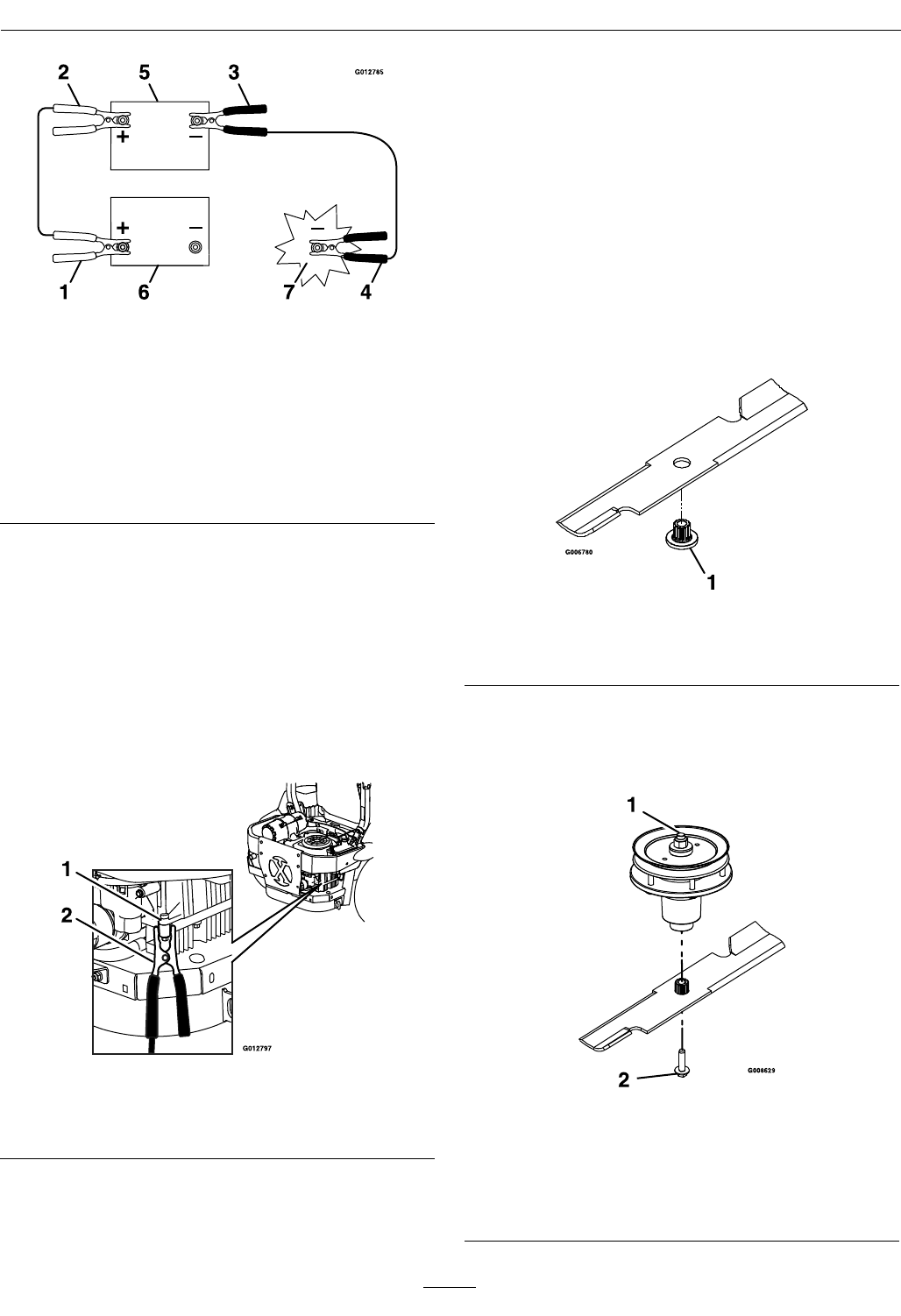
3.Connectthepositive(+)cabletothepositive(+)
terminalofthedischargedbatterythatiswiredto
thestarterorsolenoidasshowninFigure19.
32
Maintenance
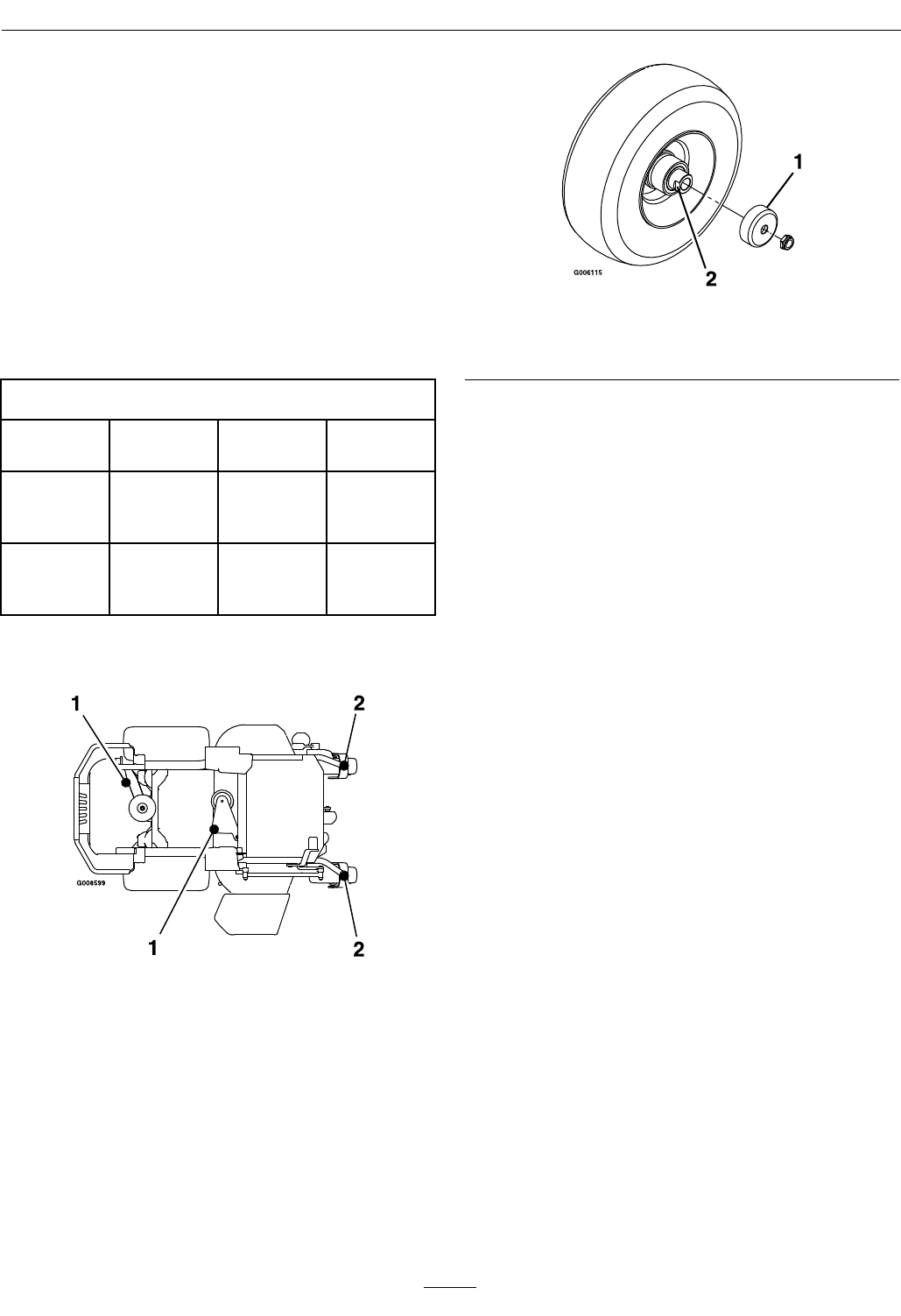
Figure19
1.Positive(+)cableondischargedbattery
2.Positive(+)cableonboosterbattery
3.Negative(–)cableontheboosterbattery
4.Negative(–)cableontheengineblock
5.Boosterbattery
6.Dischargedbattery
7.Engineblock
4.Connecttheotherendofthepositivecabletothe
positiveterminaloftheboosterbattery.
5.Connecttheblacknegative(–)cabletotheother
terminal(negative)oftheboosterbattery.
6.MAKETHEFINALCONNECTIONON
THEENGINEBLOCKOFTHESTALLED
VEHICLE(NOTTOTHENEGATIVEPOST)
AWAYFROMTHEBATTERY .STANDBACK
(seeFigure20).
Figure20
1.Engineblock
2.Negative(–)cable
7.Startthevehicleandremovethecablesinthe
reverseorderofconnection(theengineblock
(black)connectionisthersttodisconnect).
CheckMowerBlades
ServiceInterval:Beforeeachuseordaily
1.Stopengine,waitforallmovingpartstostop,and
removekey.Engageparkingbrake.
2.Liftdeckandsecureinraisedpositionasstatedin
theCleanGrassBuild-UpUnderDecksection.
3.Inspectbladesandsharpenorreplaceasrequired.
4.Reinstalltheblades(iftheywereremoved)inthe
followingorder:
A.Installbushingthroughbladewithbushing
angeonbottom(grass)sideofblade.
Figure21
1.Installbushinginbladepriortoinstallingbushingin
spindle.
B.Installbushing/bladeassemblyintospindle.
Makesurethesplinesonthebushingare
engagedinthespindlebeforetighteningthe
bolt.
Figure22
1.Usewrenchhereforbladeinstallation.Thisnuthas
beentorquedto90-110ft-lb(122-149N-m)
2.Torqueto55-60ft-lb(75-81N-m)Applylubricantto
threadsasneededtopreventseizing.Copper-based
anti-seizepreferable.Greaseacceptablesubstitute.
33

Maintenance
C.Applylubricanttothreadsofbladeboltto
preventseizing.Copper-basedanti-seize
preferable.Greaseacceptablesubstitute.
Installbladeboltngertight.Placewrench
onthetopspindlenutthentorquetheblade
boltsto55-60ft-lb(75-81N-m).
WARNING
Incorrectinstallationofthebladeor
componentsusedtoretainthebladecan
bedangerous.Failuretousealloriginal
componentsandassembledasshowncould
allowabladeorbladecomponenttobe
thrownoutfromunderthedeckresultingin
seriouspersonalinjuryordeath.
AlwaysinstalltheoriginalExmarkblades,
bladebushings,andbladeboltsasshown.
CheckSafetyInterlock
System
ServiceInterval:Beforeeachuseordaily
Note:Topreventenginecut-outsonroughterrain
theseatkillswitchhasa1/2seconddelay.
1.Checkstartingcircuit.Startershouldcrankwith,
parkingbrakeengaged,PTOdisengagedand
motioncontrolleversmovedoutintheneutral
lockposition.Theoperatordoesnotneedtobe
intheseattostarttheengine.
Trytostartwithoperatorinseat,parkingbrake
disengaged,PTOdisengagedandmotioncontrol
leversintheneutrallockposition-startermust
notcrank.
Trytostartwithoperatorinseat,parkingbrake
engaged,PTOengagedandmotioncontrol
leversintheneutrallockposition-startermust
notcrank.
Trytostartwithoperatorinseat,parking
brakeengaged,PTOdisengaged,andtheleft
motioncontrolleverin,startermustnotcrank,
repeatagainwiththerightleverin,thenwith
bothleversin-startermustnotcrank.
2.Checkthekillcircuits.Runengineatone-third
throttle,disengageparkingbrakeandraiseoff
ofseat(butdonotgetoffofmachine)engine
mustinitiateshutdownafterapproximately1/2
secondhaselapsed(seathastimedelaykillswitch
topreventcut-outsonroughterrain).
Runengineatone-thirdthrottle,engagePTO
andraiseoffofseat(butdonotgetoffof
machine)enginemustinitiateshutdownafter
onesecondhaselapsedifthehandlesarein.The
delaywillbe1/2secondifthehandlesareout.
Runengineatone-thirdthrottle,withbrake
disengaged,moveleversinandraiseoffseat(but
donotgetoffofmachine)enginemustinitiate
shutdownafter1/2secondhaselapsed.
Again,runengineatone-thirdthrottle,brake
engaged,andmoveleftmotioncontrollever
in-enginemustinitiateshutdownafter1/2
secondhaselapsed.
Repeatagainmovingtherightleverin,then
movingbothleversin-enginemustinitiate
shutdownafter1/2secondhaselapsedwhether
operatorisonseatornot.
Note:Ifmachinedoesnotpassanyofthesetests,
donotoperate.ContactyourauthorizedEXMARK
SERVICEDEALER.
Important:Itisessentialthatoperatorsafety
mechanismsbeconnectedandinproper
operatingconditionpriortouseformowing.
CheckRolloverProtections
Systems(RollBar)Knobs
ServiceInterval:Beforeeachuseordaily
Checkthatboththemountinghardwareandthe
knobsareingoodworkingcondition.Makesurethe
knobsarefullyengagedwiththeROPSintheraised
position.Theupperhoopoftherollbarmayneed
tobepushedforwardorpulledrearwardtogetboth
knobsfullyengaged.
34
Maintenance
Figure23
1.Engaged2.Partiallyengaged—Do
NotoperatewithROPS
inthiscondition.
CheckSeatBelt
ServiceInterval:Beforeeachuseordaily
Visuallyinspectseatbeltforwear,cuts,andproper
operationofretractorandbuckle.Replacebefore
operatingifdamaged.
CheckforLooseHardware
ServiceInterval:Beforeeachuseordaily
1.Stopengine,waitforallmovingpartstostop,and
removekey.Engageparkingbrake.
2.Visuallyinspectmachineforanyloosehardware
oranyotherpossibleproblem.Tightenhardware
orcorrecttheproblembeforeoperating.
ServiceAirCleaner
ServiceInterval:Every250hours—Replace
theprimaryaircleaner
element—check
secondaryaircleaner
element;replaceifdirty.
(Mayneedmoreoften
undersevereconditions.
SeetheEngineOwner's
Manualforadditional
information.)
Every500hours—Replace
thesecondaryaircleaner
element(Mayneedmore
oftenundersevere
conditions.Seethe
EngineOwner'sManual
foradditionalinformation.)
1.Stopengine,waitforallmovingpartstostop,and
removekey.Engageparkingbrake.
2.SeetheEngineOwner'sManualformaintenance
instructions.
CheckAirFilterAssembly(if
equipped)
ServiceInterval:Asrequired
Important:Topreventenginedamage,always
operatetheenginewithbothairltersandcover
installed.
1.Whencheckingorreplacingtheairlterelement,
makesuretheairlterassemblyisinstalledinthe
brackets.
2.Positiontheaircleanercoversothatthe
breathervalvedoesnotinterferewiththethrottle
mechanism.
G016165
1
2
3
Figure24
1.Aircleanercover3.Breathervalve
2.Throttlemechanism
3.Securethecoverwithlatches.
ChangeEngineOil
ServiceInterval:Aftertherst5hours
Every100hours/Yearly
(whichevercomesrst)
35
Maintenance
(Mayneedmoreoften
undersevereconditions.)
1.Stopengine,waitforallmovingpartstostop,and
removekey.Engageparkingbrake.
2.Drainoilwhileengineiswarmfromoperation.
3.Theoildrainhoseislocatedonrighthandside
ofengineattherear.Placepanundermachine
tocatchoil.Removeplugfromendofdrain
hose.Allowoiltodrainandreplaceoildrainplug.
Torqueplugto20-24ft-lb.
4.Replacetheoilltereveryotheroilchange.Clean
aroundoillterandunscrewltertoremove.
Beforereinstallingnewlter,applyathincoating
ofExmark4–CyclePremiumEngineoilonthe
surfaceoftherubberseal.Turnlterclockwise
untilrubbersealcontactsthelteradapterthen
tightenlteranadditional1/2to3/4turn.
5.Cleanaroundoilllcapandremovecap.Fillto
speciedcapacityandreplacecap.
6.UseoilrecommendedintheCheckEngineOil
Levelsection.DoNotoverll.Starttheengine
andcheckforleaks.
7.Wipeupanyspilledoilfromenginedeck
mountingsurfaces.
CheckHydraulicOilLevel
ServiceInterval:Every50hours
1.Stopengineandwaitforallmovingpartstostop.
Engageparkingbrake.
2.Waituntiltheunitcoolsbeforecheckingthe
hydraulicoil.
3.Slidetheseatallthewayback,thenlifttheseatto
accessthecapsontheLHandRHhydrodrives.
4.Cleantheareaaroundhydraulicreservoircapand
removecap.
5.Wipethedipstickcleanandre-insertthecapback
intothehydro.Lightlytightenthecap.
6.Removethecapagainandcheckthelevelofthe
oilonthedipstick.SeeFigure25foroillevels.
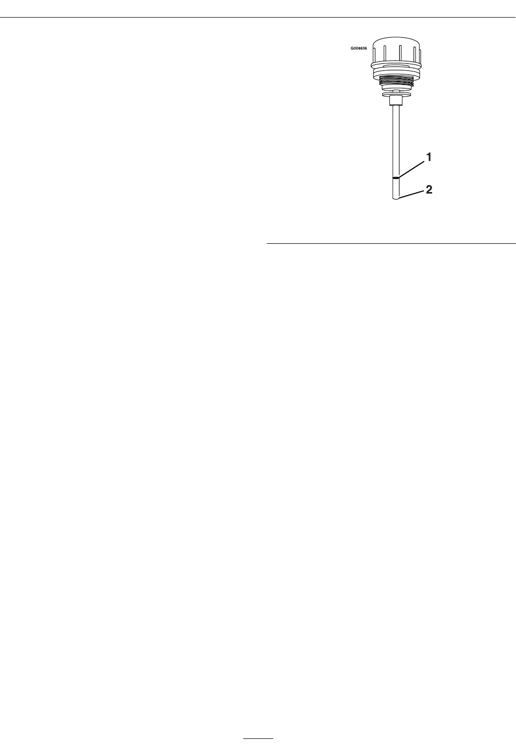
Figure25
1.Full2.Add
Note:Theoillevelonthedipstickwillbe
incorrectiftheoilischeckedwhentheunitishot.
7.Ifthedipstickoillevelisatthe“add”markadd
ExmarkPremiumHydroOil.
8.Replacehydraulicreservoircapandtightenuntil
snug.DoNotovertighten.
CheckTirePressures
ServiceInterval:Every50hours
1.Stopengine,waitforallmovingpartstostop,and
removekey.Engageparkingbrake.
2.Checktirepressureindrivetires.
3.Inatedrivetiresto13psi(90kPa).
4.Semi-pneumaticcastertiresDoNotneedtobe
inated.
Note:DoNotaddanytypeoftirelinerorfoam
llmaterialtothetires.Excessiveloadscreatedby
foamlledtiresmaycausefailurestothehydrodrive
system,frame,andothercomponents.Foamlling
tireswillvoidthewarranty.
CheckConditionOfBelts
ServiceInterval:Every50hours
1.Stopengine,waitforallmovingpartstostop,and
removekey.Engageparkingbrake.
2.Removeleftandrightbeltshieldsondeckandlift
upoorpantoinspectdeckdrivebelt.
3.Checkundermachinetoinspectthepumpdrive
belt.
36
Maintenance
Note:Noadjustmentsarerequiredforbelt
tension.
LubricateGreaseFittings
Note:Seechartforserviceintervals.
1.Stopengine,waitforallmovingpartstostop,and
removekey.Engageparkingbrake.
2.Lubricatettingswithonetotwopumpsof
NGLIgrade#2multi-purposegungrease.
Refertothefollowingchartforttinglocations
andlubricationschedule.
LubricationChart
Fitting
Locations
Initial
Pumps
Numberof
Places
Service
Interval
1.Deckand
PumpIdler
Pivots
12Yearly
2.Front
Caster
Pivots
*02*Yearly
*Seestep3forspeciallubricationinstructionson
thefrontcasterpivots.
3.Lubricatefrontcasterpivotsonceayear.Remove
hexplugandcap.Threadgreasezerkinholeand
pumpwithgreaseuntilitoozesoutaroundtop
bearing.Removegreasezerkandthreadplugback
in.Placecapbackon.
LubricateCasterWheelHubs
ServiceInterval:Asrequired
1.Stopengine,waitforallmovingpartstostop,and
removekey.Engageparkingbrake.
Figure26
1.Sealguard2.Spacernutwithwrench
ats
2.Removecasterwheelfromcasterforks.
3.Removesealguardsfromthewheelhub.
4.Removeoneofthespacernutsfromtheaxle
assemblyinthecasterwheel.Notethatthread
lockingadhesivehasbeenappliedtolockthe
spacernutstotheaxle.Removetheaxle(withthe
otherspacernutstillassembledtoit)fromthe
wheelassembly.
5.Pryoutseals,andinspectbearingsforwearor
damageandreplaceifnecessary.
6.PackthebearingswithaNGLIgrade#1
multi-purposegrease.
7.Insertonebearing,onenewsealintothewheel.
Note:Seals(ExmarkP/N103-0063)mustbe
replaced.
8.Iftheaxleassemblyhashadbothspacernuts
removed(orbrokenloose),applyathreadlocking
adhesivetoonespacernutandthreadontothe
axlewiththewrenchatsfacingoutward.Do
Notthreadspacernutallofthewayontotheend
oftheaxle.Leaveapproximately1/8inch(3mm)
fromtheoutersurfaceofthespacernuttothe
endoftheaxleinsidethenut.
9.Inserttheassemblednutandaxleintothewheel
onthesideofthewheelwiththenewsealand
bearing.
10.Withtheopenendofthewheelfacingup,ll
theareainsidethewheelaroundtheaxlefullof
NGLIgrade#1multi-purposegrease.
11.Insertthesecondbearingandnewsealintothe
wheel.
12.Applyathreadlockingadhesivetothe2ndspacer
nutandthreadontotheaxlewiththewrenchats
facingoutward.
37

Maintenance
13.Torquethenutto75-80in-lb(8-9N-m),loosen,
thenre-torqueto20-25in-lb(2-3N-m).Make
sureaxledoesnotextendbeyondeithernut.
14.Reinstallthesealguardsoverthewheelhuband
insertwheelintocasterfork.Reinstallcasterbolt
andtightennutfully.
Important:Topreventsealandbearingdamage,
checkthebearingadjustmentoften.Spinthe
castertire.Thetireshouldnotspinfreely
(morethan1or2revolutions)orhaveanyside
play.Ifthewheelspinsfreely,adjusttorqueon
spacernutuntilthereisaslightamountofdrag.
Reapplythreadlockingadhesive.
LubricateDeckLiftPivot
ServiceInterval:Every100hours
1.Stopengine,waitforallmovingpartstostop,and
removekey.Engageparkingbrake.
2.Lubricatedeckliftpivotwithaspraytype
lubricantorlightoil.
CheckSparkPlugs
ServiceInterval:Every200hours
Removesparkplugs,checkconditionandresetgaps,
orreplacewithnewplugs.SeeEngineOwner's
Manual.
ChangeFuelFilter
ServiceInterval:Asrequired
Afuellterisinstalledbetweenthefueltankandthe
engine.Replacewhennecessary.
ForKohlerEFIUnits:
WARNING
Fuelsystemcomponentsareunderhigh
pressure.Theuseofimpropercomponentscan
resultinsystemfailure,gasolineleakageand
possibleexplosion.
Useonlyapprovedfuellinesandfuelltersfor
highpressuresystems.
ReplacementFilters
KohlerKohlerP/N2405013
KawasakiKawasaki
P/N49019-7005
KohlerEFIKohlerP/N2505042
Note:Itisimportanttoreinstallthefuellinehoses
andsecurewithplastictiesthesameastheywere
originallyinstalledatthefactorytokeepthefuelline
awayfromcomponentsthatcouldcausefuelline
damage.
ChangeHydraulicSystem
FilterandFluid
ServiceInterval:Aftertherst250hours
Every500hoursthereafter
Note:OnlyuseExmarkHydroFilter–PartNo.
116-0164forsummerorwinter.
1.Stopengine,waitforallmovingpartstostop,and
removekey.Engageparkingbrake.
2.Raisetherearofmachineupandsupportwith
jackstands(orequivalentsupport)justhigh
enoughtoallowdrivewheelstoturnfreely.
CAUTION
Raisingthemowerdeckforserviceor
maintenancerelyingsolelyonmechanical
orhydraulicjackscouldbedangerous.The
mechanicalorhydraulicjacksmaynotbe
enoughsupportormaymalfunctionallowing
theunittofall,whichcouldcauseinjury.
DoNotrelysolelyonmechanicalorhydraulic
jacksforsupport.Useadequatejackstands
orequivalentsupport.
3.Removethepumpdrivebelt.
4.Placeacatchpanunderthehydro.
5.Carefullycleanareaaroundthelters.Itis
importantthatnodirtorcontaminationenterthe
hydraulicsystem.
6.Usingasocket,unscrewlterstoremoveand
allowoiltodrain.
7.Beforeinstallingthenewlters,applyathincoat
ofExmarkPremiumHydroOilonthesurface
ofthetworubberseals.
38

Maintenance
8.Installthenewltersandtorqueto14ft-lb(19
N-m).
9.FillthehydraulicsystemasstatedinCheck
HydraulicOilLevelsection.
ExmarkPremiumHydroOilisrecommended.
Refertothechartforanacceptablealternative:
HydroOilServiceInterval
ExmarkPremiumHydro
Oil(Preferred)
Afterrst250hours
*Every500hours
thereafter
Mobil115W50Afterrst250hours
*Every250hours
thereafter
*Mayneedmoreoftenundersevereconditions.
10.Removethecatchpanandproperlydisposeof
hydrooilandlteraccordingtolocalcodes.
11.Re-installthepumpdrivebelt.
12.Startengineandmovethrottlecontrolaheadto
fullthrottleposition.Movethespeedcontrol
leverstothefullspeedandrunforoneminute.
Shutdownthemachine,allowthehydrostocool
andrecheckoillevel.
13.Removethejackstands.
Note:DoNotchangethehydraulicsystemoil
(exceptforwhatcanbedrainedwhenchanginglter),
unlessitisfelttheoilhasbeencontaminatedorbeen
extremelyhot.
Changingoilunnecessarilycoulddamagehydraulic
systembyintroducingcontaminantsintothesystem.
WheelHub-SlottedNut
TorqueSpecication
ServiceInterval:Aftertherst100hours
Every500hoursthereafter
Torquetheslottednutto211-260ft-lb(286-352
N-m).
Note:DoNotuseanti-seizeonwheelhub.
CheckSparkArrester
(ifequipped)
ServiceInterval:Every50hours
WARNING
Hotexhaustsystemcomponentsmayignite
gasolinevaporsevenaftertheengineisstopped.
Hotparticlesexhaustedduringengineoperation
mayigniteammablematerials.Firemayresult
inpersonalinjuryorpropertydamage.
DoNotrefuelorrunengineunlesssparkarrester
isinstalled.
1.Stopengine,waitforallmovingpartstostop,and
removekey.Engageparkingbrake.
2.Waitformufertocool.
3.Ifanybreaksinthescreenorweldsareobserved,
replacearrester.
4.Ifpluggingofthescreenisobserved,remove
arresterandshakelooseparticlesoutofthe
arresterandcleanscreenwithawirebrush(soak
insolventifnecessary).Reinstallarresteron
exhaustoutlet.
ThreadLockingAdhesives
Threadlockingadhesivessuchas“Loctite242”
or“Fel-Pro,Pro-LockNutType”areusedonthe
followingfasteners:
•ROPSspringpinhousing.
•Hydropumpcontrolarm,linkagebolt,and
attachmentbolt.
•Hydrocoolingfanscrew .
•Hydroparkbrakecableanchormountingbolt
•Sheaveandclutchretainingboltintheendof
enginecrankshaft.
Threadlockingadhesivesarerequiredforsome
hardwareonengines—seetheEnginemanual.
MobilHTSGrease(Or
Food-GradeAnti-seize)
MobilHTSgrease(orfood-gradeanti-seize)isused
inthefollowinglocations:
•Betweenthejackshaftandbearings.
•Betweenthejackshaftandsheaves,spindles,and
bearings.
39

Maintenance
•Betweenthespindlesandsheaves.
•Undertopcutterhousingbearingguard.
Copper-BasedAnti-seize
Copper-basedanti-seizeisusedinthefollowing
location:
OnthreadsofBladeBolts.SeeCheckMower
Bladessection.
DielectricGrease
Dielectricgreaseisusedonallbladetypeelectrical
connectionstopreventcorrosionandlossofcontact.
Dielectricgreaseshouldnotbeappliedtosealed
connectors.
Adjustments
Note:DisengagePTO,shutoffengine,waitfor
allmovingpartstostop,engageparkingbrake,and
removekeybeforeservicing,cleaning,ormakingany
adjustmentstotheunit.
CAUTION
Raisingthemowerdeckforserviceor
maintenancerelyingsolelyonmechanical
orhydraulicjackscouldbedangerous.The
mechanicalorhydraulicjacksmaynotbeenough
supportormaymalfunctionallowingtheunitto
fall,whichcouldcauseinjury.
DoNotrelysolelyonmechanicalorhydraulic
jacksforsupport.Useadequatejackstandsor
equivalentsupport.
DeckLeveling
1.Positionthemoweronaatsurface.
2.Stopengine,waitforallmovingpartstostop,and
removekey.Engageparkingbrake.
3.Checkthetirepressureinthedrivetires.Proper
inationpressurefortiresis13psi(90kPa).
Adjustifnecessary.
4.Positionthetransportlockinthelatching
position.
5.Pushthefootpedalallthewayforwardandthe
deckwilllatchatthe51/2inch(14cm)transport
position(Figure27).
40
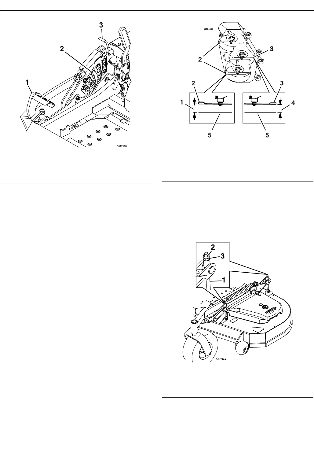
Maintenance
Figure27
1.Footlever3.Transportlock
2.Heightofcutpin
6.Inserttheheightadjustmentpinintothe3inch
(7.6cm)cuttingheightlocation.
7.Releasethetransportlockandallowthedeckto
lowertothecuttingheight.
8.Raisethedischargedeector.
9.Measurefromthelevelsurfacetothefronttipof
thecenterblade.Themeasurementshouldread
3inches(7.6cm).
Note:Inmostconditions,thebackbladetip
shouldbeadjusted1/4inch(6.4mm)higherthan
thefront.
Figure28
1.31/4inches(8.3cm)4.3inches(7.6cm)
2.Backbladetip5.Levelsurface
3.Frontbladetip
10.Loosenthejamnutsonthetopofeachdeck
link.Finetunetheadjusteronthefrontdeck
liftassemblybyturningittoget3inch(7.6cm)
height(seeFigure29).
Toincreasetheheight,turntheadjusterclockwise;
todecrease,turncounterclockwise.
Figure29
1.Adjusterlink3.Adjuster
2.Jamnut
11.Thebacktipofthebladeshouldmeasure3
1/4inches(8.3cm).Finetunerearadjustersas
required.
41
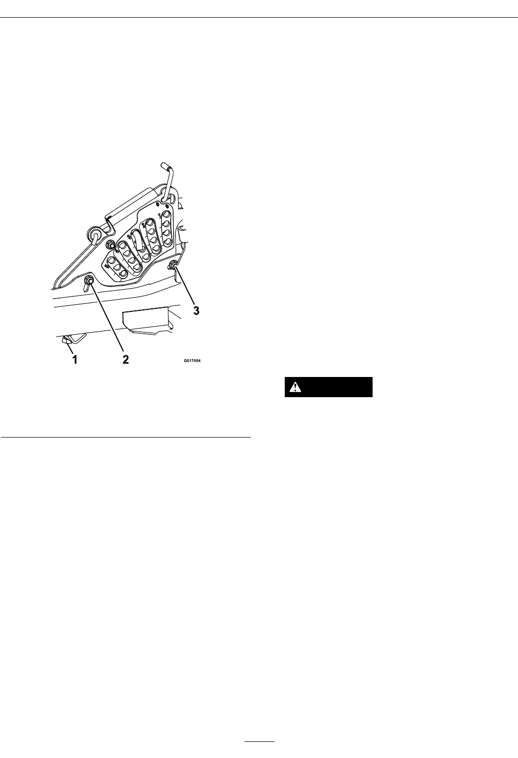
Maintenance
12.Re-measureuntilallfoursidesarethecorrect
height.Tightenallthejamnutsonthedecklift
armassemblies.
13.Lowerdischargedeector.
14.Ifthefourdecklinksdonothaveenough
adjustmenttoachieveaccuratecutheightwiththe
desiredrake,thesinglepointadjustmentcanbe
utilizedtogainmoreadjustment(seeFigure30).
Figure30
1.Singlepointheightadjustmentbolt
2.Frontheight-of-cutplatemountingbolt
3.Rearheight-of-cutplatemountingbolt
15.Toadjustthesinglepointsystem,rstloosenthe
frontandrearheight-of-cutplatemountingbolts.
16.Ifthedeckistoolow,tightenthesinglepoint
adjustmentboltbyrotatingitclockwise.If
thedeckistoohigh,loosenthesinglepoint
adjustmentboltbyrotatingitcounterclockwise.
Note:Loosenortightenthesinglepoint
adjustmentboltenoughtomovetheheight-of-cut
platemountingboltsatleast1/3thelengthof
theavailabletravelintheirslots.Thiswillregain
someupanddownadjustmentoneachofthe
fourdecklinks.
17.Re-tightenfrontandrearheight-of-cutplate
mountingbolts.
Important:Torquethefrontandrear
height-of-cutplatemountingboltsto27-33
ft-lb(37-45N-m).
18.Repeatsteps9through13.
PumpDriveBeltTension
Self-tensioning-Noadjustmentnecessary.
DeckBeltTension
Self-tensioning-Noadjustmentnecessary.
AdjustingtheParkingBrake
ServiceInterval:Aftertherst100hours
Every500hoursthereafter
Checktomakesurebrakeisadjustedproperly.This
proceduremustbefollowedaftertherst100hours
orwhenabrakecomponenthasbeenremovedor
replaced.
1.Drivethemachineontoalevelsurface.
2.Disengagethebladecontrolswitch(PTO),move
themotioncontrolleverstotheneutrallocked
positionandsettheparkingbrake.
3.Stoptheengine,waitforallmovingpartstostop,
andremovethekey.
4.Raisethebackofthemachineupandsupportthe
machinewithjackstands.
CAUTION
Raisingthemowerdeckforserviceor
maintenancerelyingsolelyonmechanical
orhydraulicjackscouldbedangerous.The
mechanicalorhydraulicjacksmaynotbe
enoughsupportormaymalfunctionallowing
theunittofall,whichcouldcauseinjury.
DoNotrelysolelyonmechanicalorhydraulic
jacksforsupport.Useadequatejackstands
orequivalentsupport.
5.Removethereartiresfromthemachine.
6.Removeanydebrisfromthebrakearea.
7.Rotatethedrivewheelreleasehandletothe
“released”position.RefertotheDriveWheel
ReleaseValvessectioninOperation.
8.Measuretheoveralllengthofthecompression
spring.Thecorrectlengthshouldbebetween
11/2–19/16inches(3.8–4.0cm).Ifthespring
lengthiswithinthisrange,noadjustmentis
needed.Ifitisnot,proceedtostep9.
9.Holdthethreadedrodendwithatoolandadjust
thelocknutuntilthespringlengthisbetween
11/2–19/16inches(3.8–4.0cm)seeFigure31).
42
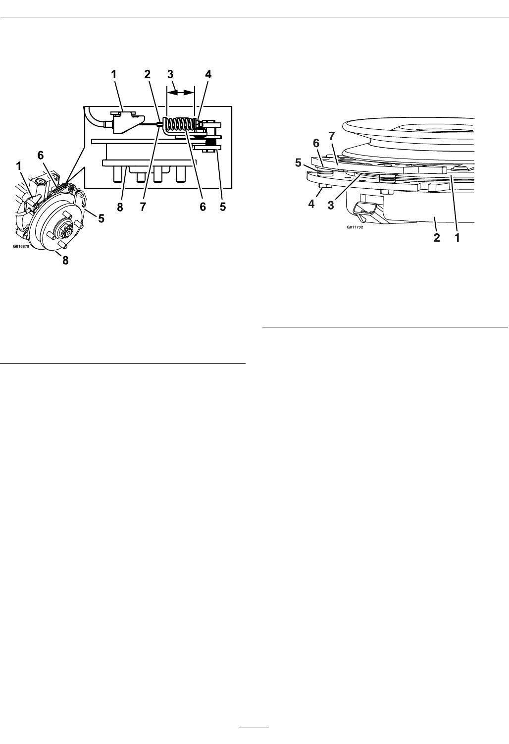
Maintenance
DoNotallowthecabletoturnwhenthenutsare
beingloosened.
Figure31
LeftHandBrakeShown
1.Cableanchor5.Caliper
2.Holdthreadedrodhere6.Compressionspring
3.Measure7.Threadedrod
4.Locknut8.Hub
10.Disengagetheparkbrake.Turnthewheelhub
byhandinbothdirectionsrelativetothecaliper;
nodragofthecaliperpadonthewheelhubis
desired.
11.Ifthereisnomovementbetweenthehubandthe
caliperthenrepeattheadjustment(driverelease
valvesmustbeinthe“released”positiononthe
hydros).
12.Afteradjustingthebrakesonbothsidesofthe
mower,cyclethebrakehandleaminimumofsix
timestoallowthecabletoseatintothesheath
andmountingtabs.
13.Recheckthespringlength;engagetheparkbrake
andrepeatsteps8through11ifthelengthisnot
inthecorrectrange.
14.Rotatethedrivewheelreleasehandletothe
“operating”position.RefertotheDriveWheel
ReleaseValvessectioninOperation.
15.Installthereartiresandtorquelugnutsto90-95
ft-lb(122-129N-m).
16.Removejackstands.
ElectricClutchAdjustment
Noadjustmentnecessary.Howeverwhentheclutch
brakehasworntothepointwheretheclutchno
longerengagesconsistently,theshimcanberemoved
toextendtheclutchlife.
Figure32
1.Armature5.Brakespacer
2.Fieldshell6.Re-gapshim
3.Rotor7.Brakepole
4.Brakemountingbolt
RemovingtheShim:
1.Stopengine,waitforallmovingpartstostop,
andremovekey.Engageparkingbrake.Allow
themachinetocoolcompletelybeforestarting
theseinstructions.
2.Usingapneumaticline,blowoutanydebris
fromunderthebrakepoleandaroundthebrake
spacers.
3.Checktheconditionofthewireharnessleads,
connectors,andterminals.Cleanorrepairas
necessary.
4.Verifythat12Vispresentattheclutchconnector
whenthePTOswitchisengaged.
5.Measurethegapbetweentherotorandarmature.
Ifthegapisgreaterthan.04inch(1mm),proceed
withthefollowingsteps:
A.Loosenbothbrakemountingboltsone-half
toonefullturn(seeFigure33).
Note:DoNotremovethebrakepolefrom
theeldshell/armature.Thebrakepolehas
worntomatchthearmatureandneedsto
continuetomatchaftertheshimisremoved
toensureproperbraketorque.
43
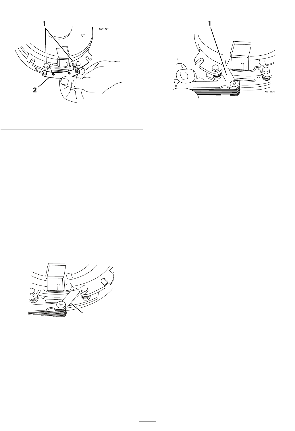
Maintenance
Figure33
1.Brakemountingbolt2.Shim
B.Usingneedlenosepliers,orbyhand,take
holdofthetabandremovetheshim(DoNot
discardtheshimuntilproperclutchfunction
hasbeenconrmed).
C.Usingapneumaticline,blowoutanydebris
fromunderthebrakepoleandaroundthe
brakespacers.
D.Re-torqueeachbolt(M6x1)to10ft-lb(13
N-m)+/-0.5ft-lb(0.7N-m).
E.Usinga0.010inchthickfeelergauge,verify
thatagapispresentbetweentherotorand
armaturefaceonbothsidesofthebrakepole
asshown.(Duetothewaytherotorand
armaturefaceswear(peaksandvalleys)itis
sometimesdifculttomeasurethetruegap.)
G011733
1
Figure34
1.Feelergauge
Figure35
1.Feelergauge
•Ifthegapislessthan0.010inch,then
reinstalltheshimandreferencethe
Troubleshootingsection.
•Ifthegapissufcient,proceedtothe
safetycheckinstepF.
F.Performthefollowingsafetycheck:
a.Sitontheseatandstarttheengine.
b.MakesurethebladesDoNotengagewith
thePTOswitch“off”andtheclutch
disengaged.
Iftheclutchdoesnotdisengage,
reinstalltheshimandreferencethe
Troubleshootingsection.
c.EngageanddisengagethePTOswitch
tenconsecutivetimestoensuretheclutch
isfunctioningproperly.Iftheclutch
doesnotengageproperly,referencethe
Troubleshootingsection.
MotionControlLinkage
Adjustment
Locatedoneithersideofthefueltank,belowtheseat
arethepumpcontrollinkages.Rotatingthepump
linkagewitha1/2inchwrenchallowsnetuning
adjustmentssothatthemachinedoesnotmovein
neutral.Anyadjustmentsshouldbemadeforneutral
positioningonly.
44
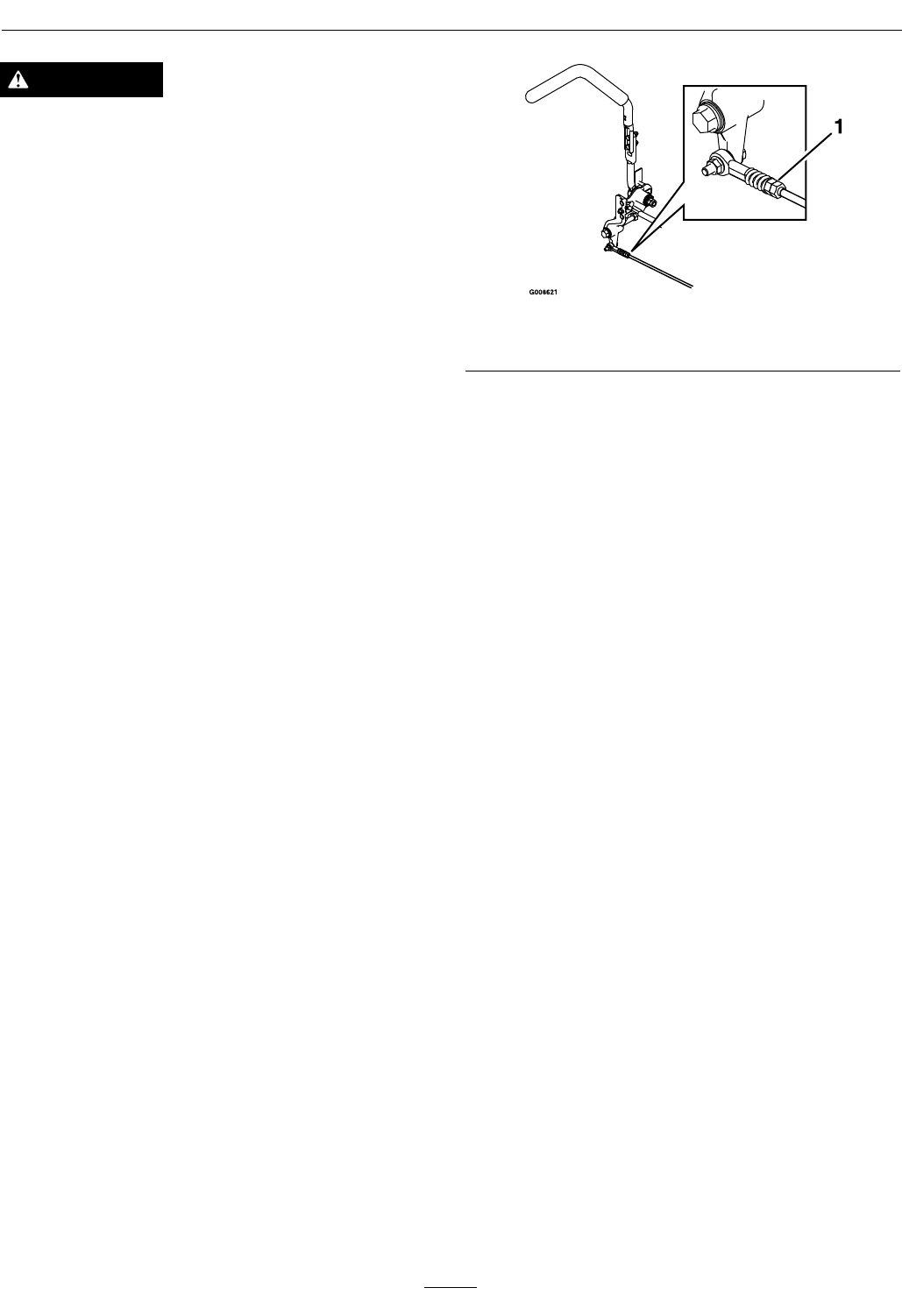
Maintenance
WARNING
Enginemustberunninganddrivewheelsmust
beturningsoadjustmentscanbeperformed.
Contactwithmovingpartsorhotsurfacesmay
causepersonalinjury.
Keepngers,hands,andclothingclearof
rotatingcomponentsandhotsurfaces.
1.Priortostartingtheengine,pushthedecklift
pedalandremovetheheightofcutpin.Lower
decktotheground.
2.Raisetherearofmachineupandsupportwith
jackstands(orequivalentsupport)justhigh
enoughtoallowdrivewheelstoturnfreely.
3.Removetheelectricalconnectionfromtheseat
safetyswitch,locatedunderthebottomcushion
oftheseat.Theswitchisapartoftheseat
assembly.
4.Temporarilyinstallajumperwireacrossthe
terminalsintheconnectorofthemainwiring
harness.
5.Startengine.Brakemustbeengagedand
motioncontrolleversouttostartengine.
Operatordoesnothavetobeintheseat
becauseofthejumperwirebeingused.Run
engineatfullthrottleandreleasebrake.
6.Runtheunitatleast5minuteswiththedrive
leversatfullforwardspeedtobringhydraulicoil
uptooperatingtemperature.
Note:Themotioncontrolleverneedstobein
neutralwhilemakinganynecessaryadjustments.
7.Bringthemotioncontrolleversintotheneutral
position.Adjustpumpcontrolrodlengths
byrotatingthedoublenutsontherodinthe
appropriatedirectionuntilthewheelsslightly
creepinreverse(Figure36).Movethemotion
controlleverstothereversepositionandwhile
applyingslightpressuretotheleverallowthe
reverseindicatorspringstobringtheleversback
toneutral.Thewheelsmuststopturningor
slightlycreepinreverse.
Figure36
1.Doublenuts
8.Shutoffunit.Removejumperwirefromwire
harnessandplugconnectorintoseatswitch.
9.Removethejackstands.
10.Raisethedeckandre-installtheheightofcutpin.
11.Checkthatthemachinedoesnotcreepinneutral
withtheparkbrakesdisengaged.
MotionControlDamper
Adjustment
Thetopdampermountingboltcanbeadjustedto
obtainamoredesiredmotioncontrolleverresistance.
SeeFigure37formountingoptions.
45
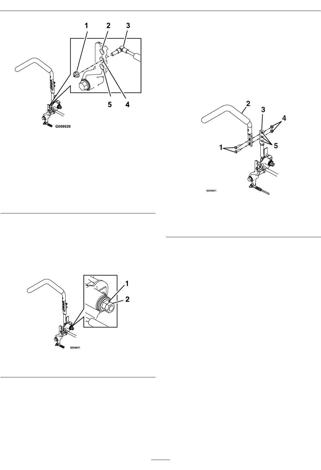
Maintenance
Figure37
RHMotionControlShown
1.Torquenylocnutto200in-lb(16.7ft-lb).Boltmust
protrudepastendofnylocnutaftertorque.AT-40Torx
bitwillbenecessarytoholdthestudfromturning.
2.Mostresistance(rmestfeel)
3.Damper
4.Mediumresistance(mediumfeel)
5.Leastresistance(softestfeel)
MotionControlNeutralLock
PivotAdjustment
Theangednutcanbeadjustedtoobtainamore
desiredmotioncontrolleverresistance(Figure38).
Figure38
1.Flangednut2.Jamnut
1.Loosenthejamnut.
2.Tightenorloosentheangednuttothedesired
feel.
Formoreresistance,tightentheangednut.
Forlessresistance,loosentheangednut
3.Tightenjamnut.
MotionControlHandle
Adjustment
Adjustingtheheight:
Themotioncontrolleverscanbeadjustedhigheror
lowerformaximumoperatorcomfort.
1.Removethetwoboltsholdingthecontrolleverto
thecontrolarmshaft(Figure39).
Figure39
1.Bolts4.Nuts
2.Controllever5.Slottedholes
3.Controlarmshaft
2.Movethecontrollevertothenextsetofholes.
Securetheleverwiththetwobolts.
3.Repeattheadjustmentfortheoppositecontrol
lever.
AdjustingtheTilt
Themotioncontrolleverscanbetiltedforeoraftfor
maximumoperatorcomfort.
1.Loosentheupperboltholdingthecontrollever
tothecontrolarmshaft.
2.Loosenthelowerboltjustenoughtopivotthe
controlleverforeoraftFigure39.Tightenboth
boltstosecurethecontrolinthenewposition.
3.Repeattheadjustmentfortheoppositecontrol
lever.
MotionControlFullForward
TrackingAdjustment
Ifthemachinetravelsorpullstoonesidewhenthe
motioncontrolleversareinthefullforwardposition,
adjustthecoverplates.
1.Loosenthescrewsonacoverplate(seeFigure40).
46
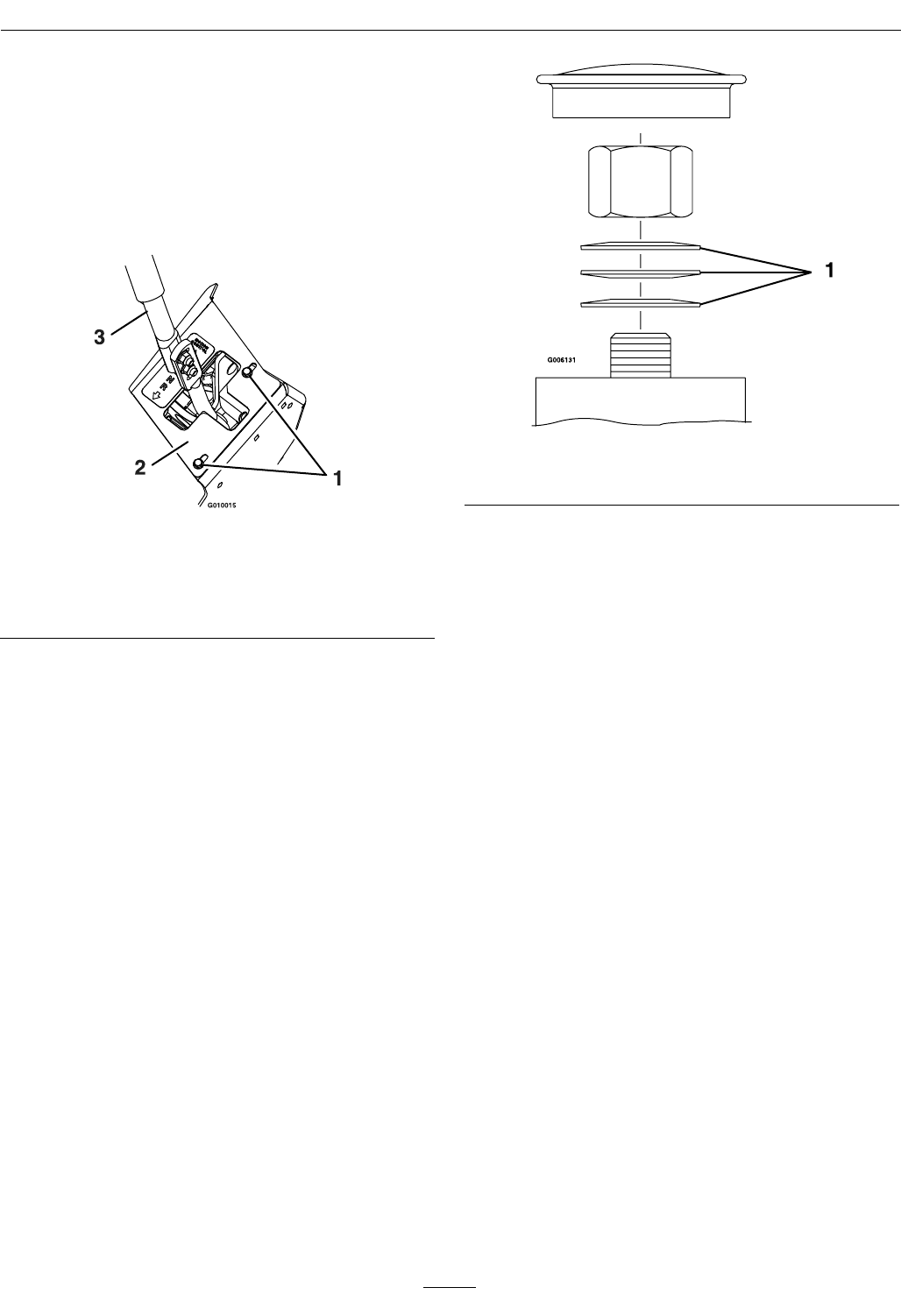
Maintenance
2.Slidethecoverplatebackwardorforwardto
adjustthetraveloftheleverandtightenthe
screws.
3.Drivethemachineandcheckthefullforward
tracking.
4.Repeatsteps1through3untildesiredtracking
isobtained.
Figure40
RHMotionControlShown
1.Screw3.Motioncontrollever
2.Coverplate
CasterPivotBearings
Pre-LoadAdjustment
Removedustcapfromcasterandtightennylocnut
untilwashersareatandbackoff1/4ofaturn
toproperlysetthepre-loadonthebearings.If
disassembled,makesurethespringdiscwashersare
reinstalledasshowninFigure41.
Figure41
1.Springdiscwashers
47

Maintenance
Cleaning
CleanEngineandExhaust
SystemArea
ServiceInterval:Beforeeachuseordaily
(Mayberequiredmore
oftenindryordirty
conditions.)
CAUTION
Excessivedebrisaroundenginecoolingair
intakeandexhaustsystemareacancauseengine,
exhaustarea,andhydraulicsystemtooverheat
whichcancreatearehazard.
Cleanalldebrisfromengineandexhaustsystem
area.
1.Stopengine,waitforallmovingpartstostop,and
removekey.Engageparkingbrake.
2.Cleanalldebrisfromrotatingengineairintake
screen,aroundengineshrouding,andexhaust
systemarea.
3.Wipeupanyexcessivegreaseoroilaroundthe
engineandexhaustsystemarea.
RemoveEngineShroudsand
CleanCoolingFins
ServiceInterval:Every100hours
1.Stopengine,waitforallmovingpartstostop,and
removekey.Engageparkingbrake.
2.Removecoolingshroudsfromengineandclean
coolingns.Alsocleandust,dirtandoilfrom
externalsurfacesofenginewhichcancause
inadequatecooling.
3.Makesurecoolingshroudsarereinstalled.
Operatingtheenginewithoutcoolingshroudswill
causeenginedamageduetooverheating.
CleanHydroFanCooling
Guards
ServiceInterval:Beforeeachuseordaily
Removingdebrisfromthehydrofancoolingguards
willallowthehydrosystemtoruncoolerandimprove
thelifeofthehydrosystem.
1.Stopengine,waitforallmovingpartstostop,and
removekey.Engageparkingbrake.
2.Slideseatallthewayback,thenlifttheseatto
accesstheLHandRHhydrodrivearea.
3.Removeaccumulateddebrisfromthehydrofan
coolingguards.
CleanDebrisFromMachine
ServiceInterval:Beforeeachuseordaily
1.Stopengine,waitforallmovingpartstostop,and
removekey.Engageparkingbrake.
2.Cleanoffanyoil,debris,orgrassbuild-uponthe
machineandcuttingdeck,especiallyunderdeck
beltshields,aroundthefueltank,aroundengine
andexhaustarea.
CleanGrassBuild-UpUnder
Deck
ServiceInterval:Beforeeachuseordaily
1.Stopengine,waitforallmovingpartstostop,and
removekey.Engageparkingbrake.
2.Raisedecktothetransport(51/2inch(14cm)
cuttingheight)position.Liftthefrontofunit
andsupportunitusingjackstandsorequivalent
support.
CAUTION
Raisingthemowerdeckforserviceor
maintenancerelyingsolelyonmechanical
orhydraulicjackscouldbedangerous.The
mechanicalorhydraulicjacksmaynotbe
enoughsupportormaymalfunctionallowing
theunittofall,whichcouldcauseinjury.
DoNotrelysolelyonmechanicalorhydraulic
jacksforsupport.Useadequatejackstands
orequivalentsupport.
3.Cleanoutanygrassbuild-upfromundersideof
deckandindischargedeector.
48

Maintenance
WasteDisposal
MotorOilDisposal
Engineoilandhydraulicoilarebothpollutantsto
theenvironment.Disposeofusedoilatacertied
recyclingcenteroraccordingtoyourstateandlocal
regulations.
BatteryDisposal
DANGER
Batteryelectrolytecontainssulfuricacid,which
ispoisonousandcancausesevereburns.
Swallowingelectrolytecanbefatalorifittouches
skincancausesevereburns.
•Wearsafetyglassestoshieldeyes,andrubber
glovestoprotectskinandclothingwhen
handlingelectrolyte.
•DoNotswallowelectrolyte.
•Intheeventofanaccident,ushwithwater
andcalladoctorimmediately.
Federallawstatesthatbatteriesshouldnotbeplaced
inthegarbage.Managementanddisposalpractices
mustbewithinrelevantfederal,state,orlocallaws.
Ifabatteryisbeingreplacedoriftheunitcontaining
thebatteryisnolongeroperatingandisbeing
scrapped,takethebatterytoalocalcertiedrecycling
center.Ifnolocalrecyclingisavailablereturnthe
batterytoanycertiedbatteryreseller.
49

Troubleshooting
Troubleshooting
Important:Itisessentialthatalloperatorsafetymechanismsbeconnectedandinproperoperating
conditionpriortomoweruse.
Whenaproblemoccurs,donotoverlookthesimplecauses.Forexample:startingproblemscouldbecaused
byanemptyfueltank.
Thefollowingtablelistssomeofthecommoncausesoftrouble.Donotattempttoserviceorreplacemajor
itemsoranyitemsthatcallforspecialtimingofadjustmentprocedures(suchasvalves,governor,etc.).Have
thisworkdonebyyourEngineServiceDealer.
Note:WhendisconnectingelectricalconnectorsDONOTpullonthewirestoseparatetheconnectors.
ProblemPossibleCauseCorrectiveAction
1.PTOisengaged.1.DisengagethePTO.
2.Parkingbrakeisnotengaged.2.Settheparkingbrake.
3.Driveleversarenotinneutrallock
position.
3.Ensurethedriveleversareintheneutral
lockposition.
4.Batterydoesnothaveafullcharge.4.Chargethebattery.SeeCheck
BatteryChargeandRecommended
JumpStartingProceduresectionsin
Maintenance.
5.Electricalconnectionsarecorroded,loose
orfaulty.
5.Checktheelectricalconnectionsfor
goodcontact.Cleanconnectorterminals
thoroughlywithelectricalcontactcleaner,
applydielectricgreaseandreconnect.
6.Fuseisblown.6.Replacetheblownfuse.
7.Relayorswitchisdefective.7.ContactanAuthorizedServiceDealer.
Starterdoesnotcrank
8.Faultymodule.8.Replacemodule.
1.Fueltankisempty.1.Fillthefueltank.
2.Fuelshutoffvalveisclosed.2.Openthefuelshutoffvalve.
3.Oillevelinthecrankcaseislow .3.Addoiltothecrankcase.
4.Thethrottleandchokearenotinthe
correctposition.
4.Besurethethrottlecontrolismidway
betweenthe“SLOW”and“FAST”
positions,andthechokeisinthe“ON”
positionforacoldengineorthe“OFF”
positionforawarmengine.
5.Dirtinfuellter.5.Replacethefuellter.
6.Dirt,water,orstalefuelisinthefuel
system.
6.ContactanAuthorizedServiceDealer.
7.Aircleanerisdirty.7.Cleanorreplacetheaircleanerelement.
8.Seatswitchisnotfunctioningproperly.8.Checktheseatswitchindicator.Replace
seatifneeded.
9.Electricalconnectionsarecorroded,loose
orfaulty.
9.Checktheelectricalconnectionsfor
goodcontact.Cleanconnectorterminals
thoroughlywithelectricalcontactcleaner,
applydielectricgreaseandreconnect.
10.Relayorswitchisdefective.10.ContactanAuthorizedServiceDealer.
11.Faultysparkplug.11.Clean,adjustorreplacesparkplug.
12.Sparkplugwireisnotconnected.12.Checkthesparkplugwireconnection.
13.Faultymodule.13.Replacemodule.
Enginewillnotstart,startshard,orfailsto
keeprunning
14.MILilluminatesandblinks14.ContactanAuthorizedServiceDealer
50

Troubleshooting
ProblemPossibleCauseCorrectiveAction
1.Engineloadisexcessive1.Reducethegroundspeed.
2.Aircleanerisdirty.2.Cleanorreplacetheaircleanerelement.
3.Oillevelinthecrankcaseislow .3.Addoiltothecrankcase.
4.Coolingnsandairpassagesforthe
engineareplugged.
4.Removetheobstructionsfromthecooling
nsandairpassages.
5.Dirtinfuellter.5.Replacethefuellter.
Enginelosespower
6.Dirt,water,orstalefuelisinthefuel
system.
6.ContactanAuthorizedServiceDealer.
Mowerpullsleftorright(withleversfully
forward)
1.Tirepressureindrivetiresnotcorrect.1.Adjusttirepressureinthedrivetires.
1.Drivereleasehandlenotin“operating”
position.
1.Positionhandlein“operating”position;
seeDriveWheelReleaseValvessection
inOperation.
2.Driveorpumpbeltisworn,looseor
broken.
2.Changethebelt.
3.Driveorpumpbeltisoffapulley.3.Changethebelt.
4.Brokenormissingidlerspring.4.Replacethespring.
Machinedoesnotdrive
5.Hydraulicuidlevelislowortoohot.5.Addhydraulicuidtoreservoirorletit
cooldown.
1.Blade(s)notsharp.1.Sharpentheblade(s).
2.Cuttingblade(s)is/arebent.2.Installnewcuttingblade(s).
3.Mowerdeckisnotlevel.3.Levelmowerdeckfromside-to-sideand
front-to-rear.
4.Undersideofmowerisdirty.4.Cleantheundersideofthemower.
5.Tirepressureindrivetiresnotcorrect.5.Adjusttirepressureinthedrivetires.
6.Bladespindlebent.6.ContactanAuthorizedServiceDealer.
Unevencuttingheight.
7.Tipsofadjacentbladesareatanuneven
cuttingheight.Bladestipsshouldbeeven
within3/16inchwhichisapproximately
onebladethickness.
7.Replaceblades,spindlesand(or)check
fordamagetomowerdeck.
1.Cuttingblade(s)is/arebentorunbalanced.1.Installnewcuttingblade(s).
2.Blademountingboltisloose.2.Tightentheblademountingbolt.
3.Enginemountingboltsareloose.3.Tightentheenginemountingbolts.
4.Looseenginepulley,idlerpulley,orblade
pulley.
4.Tightentheappropriatepulley.
5.Enginepulleyisdamaged.5.ContactanAuthorizedServiceDealer.
6.Bladespindleisbent.6.ContactanAuthorizedServiceDealer.
Abnormalvibration
7.Beltisdamaged.7.Installnewbelt.
1.Deckbeltisworn,looseorbroken.1.Installnewdeckbelt.
2.Deckbeltisoffpulley.2.Installbeltonclutchanddeckpulleys,
idlers,andtensioningidlerperrouting
decalondeck.
3.Brokenormissingidlerspring.3.Replacethespring.
Bladesdonotrotate.
4.Drivebeltnotroutedcorrectly.4.Refertobeltroutingdecalondeck.
51

Troubleshooting
ProblemPossibleCauseCorrectiveAction
1.Fuseisblown.1.Replacefuse.Checkcoilresistance,
batterycharge,chargingsystem,and
wiringconnectionsandreplaceif
necessary.
2.Lowvoltagesupplyattheclutch.2.Checkcoilresistance,batterycharge,
chargingsystem,andwiringconnections
andreplaceifnecessary.
3.Damagedcoil.3.Replaceclutch.
4.Inadequatecurrentsupply.4.Repairorreplaceclutchleadwireor
electricalsystem.Cleanconnector
contacts.
Clutchwillnotengage.
5.Rotor/armatureairgapistoolarge.5.Removeshimorreplaceclutch.
52
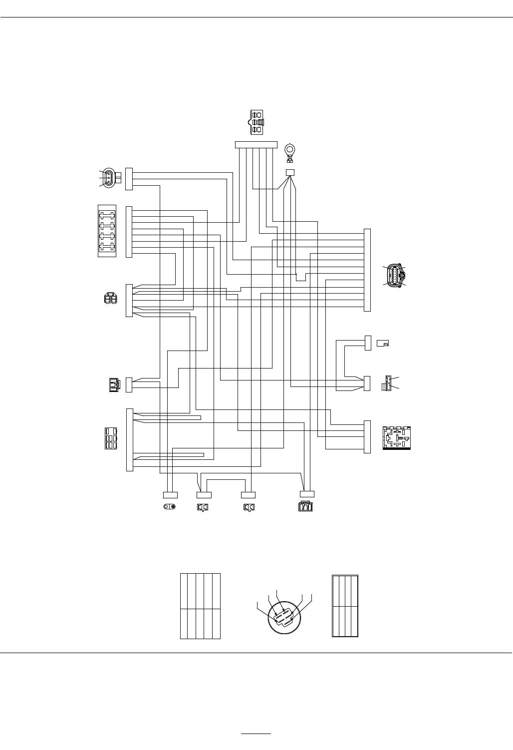
Schematics
Schematics
ElectricalDiagram—AllunitsexceptKohlerEFI
G016960
PTO SWITCH
SEAT SWITCH
IGNITION SWITCH
FUSE BLOCK
REGULATOR
GROUND
PTO CLUTCH
START RELAY
LH NEUTRAL
SWITCH
RH NEUTRAL
SWITCH
BRAKE
SWITCH
START
RED
HOUR METER/MODULE
LT. GREEN
YELLOW
TAN
BROWN
WHITE
ORANGE
GRAY VIOLET
BLUE
GREEN
RED
BLACK
ACCESSORY
ORANGE
ORANGE
MAG
PINK
FUEL SOLENOID
BROWN
BROWN
VIOLET
ENGINE
FUEL SENDER
B+
BROWN
PINK
PINK
PINK
PINK
RED
BLACK
PINK
GRAY
PINK
BLUE
BLACK
BLACK
BLACK
TVS DIODE
BROWN
BLACK
VIOLET
PINK
2 1 1 3 2 4 5 6 7 8
1
A B
2 3 1 5 4
1
2
5 4 3 1 2
1
2
1
2
9 12 3 10 1 8 6 5 11 2 4 7
B
A
7 4 5 9 3 6 8 1 2 C A B
A B
2
6
3
5
4
1
1
2
2
1
2
1
2
1
A
B
9
7
4
1 2 3
8 4
1
2
3
5
37
1
268
4
5 BC
A
31
6
45
2
5
3
2
1
4
AB
7
16
1 2
A B
IGNITION SWITCH
NOTE:
CONNECTORS VIEWED FROM MATING CONNECTOR
TERMINAL CONNECTIONS
TERMINAL A ACCESSORY
TERMINAL B BATTERY
TERMINAL I IGNITION
TERMINAL R RECTIFIER
TERMINAL S START
NONE
CIRCUIT "MAKE"
B + R + I + S
B + R + I + A
2. RUN
1. OFF
POSITION
3. START
TERMINAL A
TERMINAL I
TERMINAL R
TERMINAL S
TERMINAL B
53
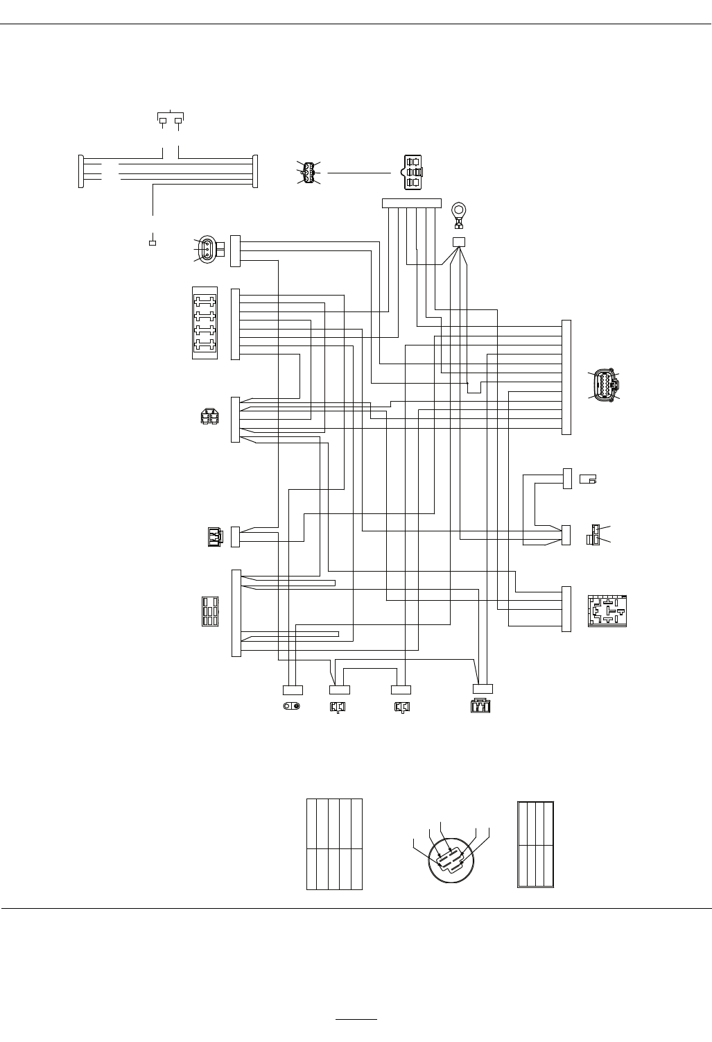
Schematics
ElectricalDiagram—KohlerEFI
G017153
STARTER
ENGINE
INDICATOR
LED
MAIN HARNESS
RED
WHITE
BLUE
RED
RED
BLACK 1
1
1
1 3
4
6 5
2
1 6 2 5 4 3
6 1 5 3 2 4
PTO SWITCH
SEAT SWITCH
IGNITION SWITCH
FUSE BLOCK
REGULATOR
GROUND
PTO CLUTCH
START RELAY
LH NEUTRAL
SWITCH
RH NEUTRAL
SWITCH
BRAKE
SWITCH
START
RED
HOUR METER/MODULE
LT. GREEN
YELLOW
TAN
BROWN
WHITE
ORANGE
GRAY VIOLET
BLUE
GREEN
RED
BLACK
ACCESSORY
ORANGE
ORANGE
MAG
PINK
FUEL SOLENOID
BROWN
BROWN
VIOLET
ENGINE
FUEL SENDER
B+
BROWN
PINK
PINK
PINK
PINK
RED
BLACK
PINK
GRAY
PINK
BLUE
BLACK
BLACK
BLACK
TVS DIODE
BROWN
BLACK
VIOLET
PINK
2 1 1 3 2 4 5 6 7 8
1
A B
2 3 1 5 4
1
2
5 4 3 1 2
1
2
1
2
9 12 3 10 1 8 6 5 11 2 4 7
B
A
7 4 5 9 3 6 8 1 2 C A B
A B
2
6
3
5
4
1
1
2
2
1
2
1
2
1
A
B
9
7
4
1 2 3
8 4
1
2
3
5
37
1
268
4
5 BC
A
31
6
45
2
5
3
2
1
4
AB
7
16
1 2
A B
IGNITION SWITCH
NOTE:
CONNECTORS VIEWED FROM MATING CONNECTOR
TERMINAL CONNECTIONS
TERMINAL A ACCESSORY
TERMINAL B BATTERY
TERMINAL I IGNITION
TERMINAL R RECTIFIER
TERMINAL S START
NONE
CIRCUIT "MAKE"
B + R + I + S
B + R + I + A
2. RUN
1. OFF
POSITION
3. START
TERMINAL A
TERMINAL I
TERMINAL R
TERMINAL S
TERMINAL B
54
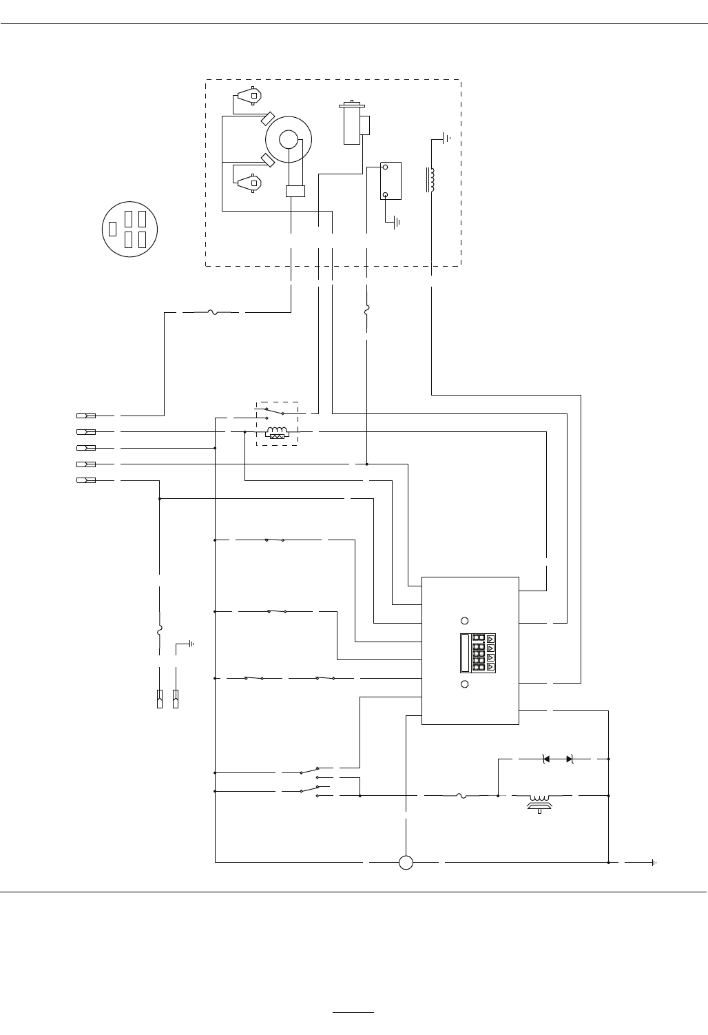
Schematics
ElectricalLogicSchematic—AllunitsexceptKohlerEFI
BN
BN
BU
BK
Y
W
T
PK
BN
PK
OR
GN
S R
PK PK
PK
LTGR
GY
GY PK
V
BN V
OR
GN
OR
R
PK
R
BK
GND
PK
BK
BN
BN
BK PK
BK
GND
15A
F4
GY
R
IBA
W
V
BU
V
V
BK
+
S
-
FUEL SENDER
10A
F3
(BRAKE)
SW6
PKOR R
F2
25A
PTO
CLUTCH
BU
1
2
5
4
7
8
(PTO SWITCH)
SW2
25A
F1
(SEAT)
SW7
2
3
5
4
1
K2
(START RELAY)
TVS DIODE
U2
(NEUT_R)
SW5
B+
MAG
REG
START
FUEL
SOLINIOD
AC
STARTER
+
-
AC
IGNITION
MODULES
SPARK PLUGSPARK PLUG
KAW TWIN-
(NEUT_L)
SW4
12
B+
10
KEY_S
9
KEY_A
4
SEAT
11
BRAKE
2
NEUTRAL
3
PTO
5
FUEL
1
START_RELAY
7
MAGNETO
6
FUEL_SOLENOID
8
GROUND
HOUR METER
2
R A
I
A
4
7
1 3
6
5
A
3
SW1
1
B
B
C
B
8
24 5
(IGNITION)
4
6
5
1
KEY SW
OPTIONAL
ACCESSORIES
2
S
Ignition switch terminal locations
viewed from back
OFF = no connections
ON = BRIA
START = BRIS
BK = BLACK
BN = BROWN
BU = BLUE
GN = GREEN
GY = GREY
LT GR = LIGHT GREEN
OR = ORANGE
PK = PINK
R = RED
T = TAN
V = VIOLET
W = WHITE
G008613
55
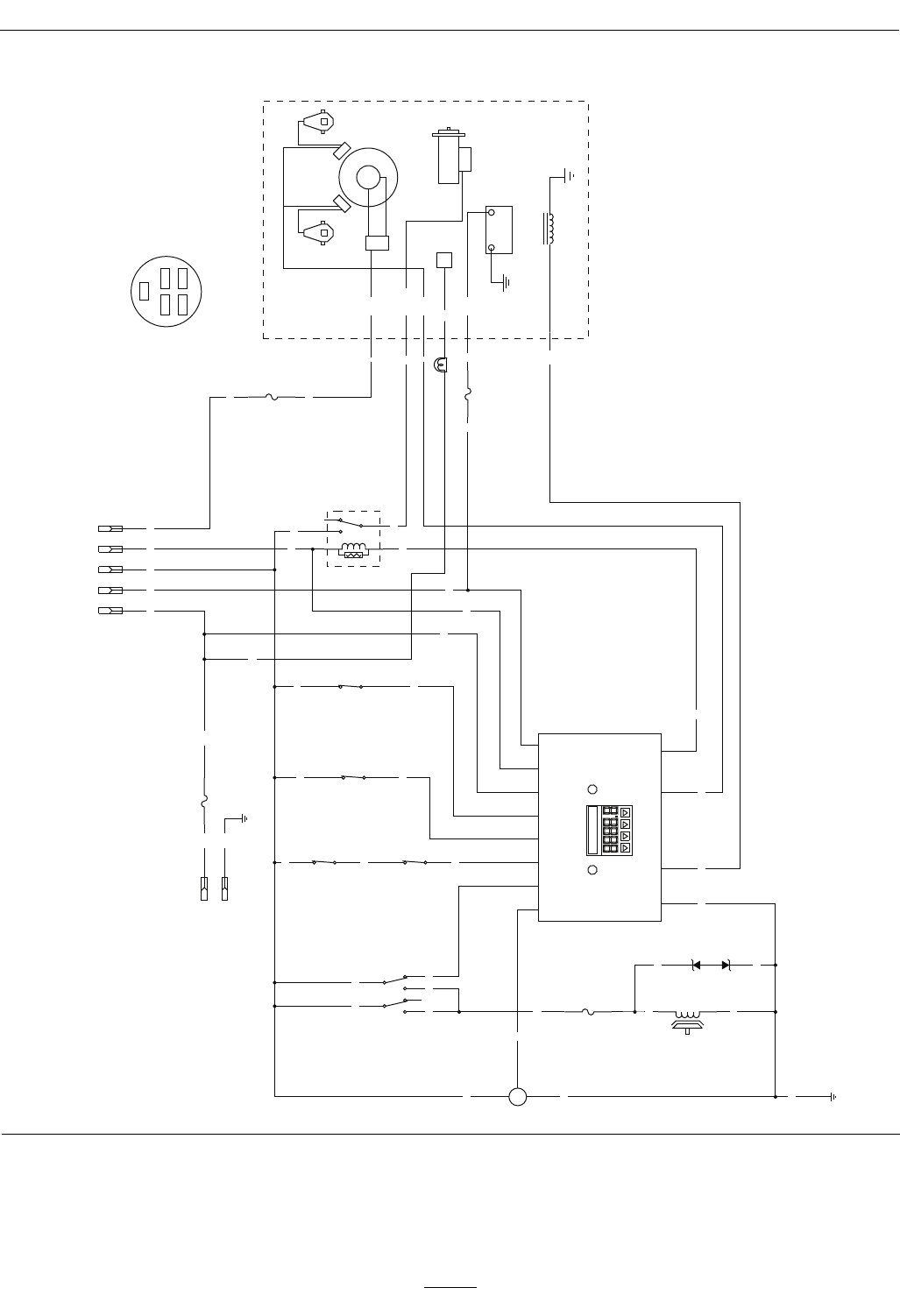
Schematics
ElectricalLogicSchematic—KohlerEFI
BN
BN
BU
BK
Y
W
T
PK
BN
R
PK
OR
GN
S R
PK PK
PK
LTGR
GY
GY PK
V
BN V
OR
GN
OR
R
PK
T
R
BK
GND
PK
BK
BN
BN
BK PK
BK
GND
15A
F4
GY
R
IBA
W
V
BU
V
V
BK
+
S
-
FUEL SENDER
10A
F3
(BRAKE)
SW6
PKOR R
F2
25A
PTO
CLUTCH
BU
1
2
5
4
7
8
(PTO SWITCH)
SW2
25A
LAMP
F1
(SEAT)
SW7
2
3
5
4
1
K2
(START RELAY)
TVS DIODE
U2
(NEUT_R)
SW5
B+
MAG
ECU
REG
START
FUEL
SOLINIOD
AC
STARTER
+
-
AC
IGNITION
MODULES
SPARK PLUGSPARK PLUG
KAW TWIN-
(NEUT_L)
SW4
12
B+
10
KEY_S
9
KEY_A
4
SEAT
11
BRAKE
2
NEUTRAL
3
PTO
5
FUEL
1
START_RELAY
7
MAGNETO
6
FUEL_SOLENOID
8
GROUND
HOUR METER
2
R A
I
A
4
7
1 3
6
5
A
3
SW1
1
B
B
C
B
8
24 5
(IGNITION)
4
6
5
1
KEY SW
OPTIONAL
ACCESSORIES
2
S
Ignition switch terminal locations
viewed from back
OFF = no connections
ON = BRIA
START = BRIS
BK = BLACK
BN = BROWN
BU = BLUE
GN = GREEN
GY = GREY
LT GR = LIGHT GREEN
OR = ORANGE
PK = PINK
R = RED
T = TAN
V = VIOLET
W = WHITE
G012212
56
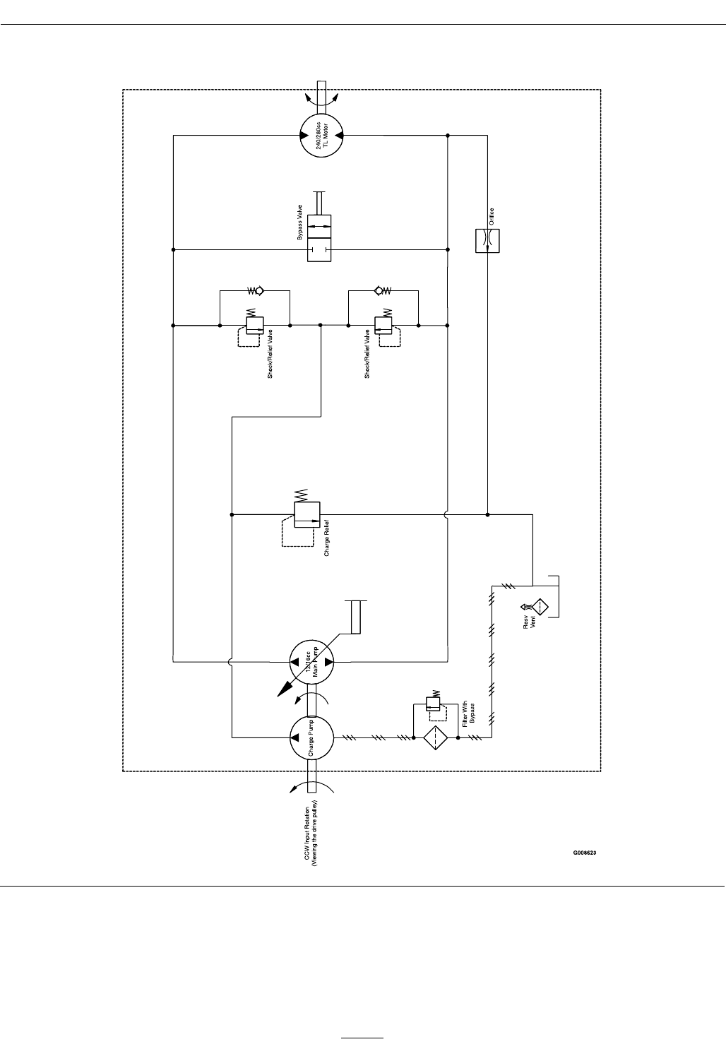
Schematics
HydraulicDiagram
57

General Warranty Conditions and Products Covered
Exmark Mfg. Co. Inc. and its affiliate, Exmark Warranty Company,
pursuant to an agreement between them, jointly warrant on the terms and
conditions herein, that we will repair, replace or adjust any part on these
products and found by us (in the exercise of our reasonable discretion) to
be defective in factory materials or workmanship.
This warranty may only be assigned or transferred to a second (or third)
owner by an authorized Exmark dealer. The warranty period commences
upon the date of the original retail purchase.
Commercial Warranty Conditions
This warranty applies to Exmark Lazer Z X-Series, Lazer Z S-Series, and
Vantage turf equipment sold in the U.S. or Canada for a period of three
years for commercial usage.
This warranty includes the cost of parts and labor for a period of two
years and the cost of parts for one additional year. This warranty does not
cover pickup and delivery charges to and from any authorized Exmark
Service Dealer.
Consumer Warranty Conditions
This warranty applies to Exmark Lazer Z X-Series, Lazer Z S-Series, and
Vantage turf equipment sold in the U.S. or Canada for a period of five
years or 750 hours (whichever occurs first) for residential usage.
Residential usage means use of the product on the same lot as your home.
Use at more than one location is considered commercial use, and the
commercial use warranty detailed above would apply.
This warranty only includes the cost of parts and labor. For the first
warrantable service repair, Exmark will cover up to $45 for associated
pick-up and delivery charges to and from any authorized Exmark Service
Dealer. Additional transportation charges may apply, contact your Dealer
for details.
Warranty Exceptions
Warranty Exceptions Warranty Period
• Bags, Belts and Tires 90 days
• Battery 1 Year Prorated
• Engine *
* The Engine warranty is covered by the engine manufacturer. Please
refer to the engine manufacturer’s warranty statement that is included in
the literature packet.
Items and Conditions Not Covered
This warranty does not cover the following:
• Any damage or deterioration due to normal use, wear and tear, or
exposure.
• Cost of regular maintenance service or parts, such as filters, fuel,
lubricants, tune-up parts, and adjustments.
• Any product or part which has been altered or misused or required
replacement or repair due to normal wear, accidents, or lack of proper
maintenance.
• Any repairs necessary due to use of parts, accessories or supplies,
including gasoline, oil or lubricants, incompatible with the turf
equipment or other than as recommended in the operator's manual or
other operational instructions provided by Exmark.
There are no other express warranties except for engine and special
emission system coverage.
All warranty work must be performed by an authorized Exmark Service
Dealer using Exmark approved replacement parts.
Instructions for Obtaining Warranty Service
The product must be registered with original proof of purchase by an
Exmark Service Dealer before obtaining any warranty service.
Contact any Exmark Service Dealer to arrange service at their dealership.
To locate a dealer convenient to you, access our website at
www.exmark.com. U.S. or Canada customers may also call
402-223-6375.
If for any reason you are dissatisfied with the Service Dealer’s analysis or
with the assistance provided, contact us at:
Exmark Customer Service Department
The Exmark Warranty Company
2101 Ashland Avenue
Beatrice, NE 68310
402-223-6375 or
service@exmark.com
Owner’s Responsibilities
If your product requires warranty service it must be returned to an
authorized Exmark service dealer within the warranty period. This
warranty extends only to turf equipment operated under normal
conditions. You must read the operator’s manual. You must also properly
service and maintain your Exmark product as described in the operator’s
manual. Such routine maintenance, whether performed by a dealer or by
you, is at your expense.
General Conditions
The sole liability of Exmark and Exmark Warranty Company with respect
to this warranty shall be repair or replacement of defective components as
set forth herein. Neither Exmark nor Exmark Warranty Company
shall be liable for any incidental or consequential loss or damage.
Such damages include but are not limited to:
• Expenses related to gasoline, oil or lubricants.
• Travel time, overtime, after hours time or other extraordinary repair
charges or charges relating to repairs or replacements outside of
normal business hours at the place of business of the authorized
Exmark Service Dealer.
• Rental of like or similar replacement equipment during the period of
any warranty, repair or replacement work.
• Any telephone or telegram charges or travel charges.
• Loss or damage to person or property other than that covered by the
terms of this warranty.
• Any claims for lost revenue, lost profit or additional cost as
a result of a claim of breach of warranty.
• Attorney's fees.
No Claim of breach of warranty shall be cause for cancellation or
rescission of the contract of sale of any Exmark mower.
All implied warranties of merchantability (that the product is fit for
ordinary use) and fitness for use (that the product is fit for a
particular purpose) are limited to the duration of the express
warranty.
Some states do not allow exclusions of incidental or consequential
damages, or limitations on how long an implied warranty lasts, so the
above exclusions and limitations may not apply to you.
This warranty gives you specific legal rights, and you may also have
other rights which vary from state to state.
Exmark Lazer Z X-Series, Lazer Z S-Series, and Vantage Turf Equipment
3 Year Limited Commercial Warranty
5 Year or 750 Hours Limited Consumer Warranty
G4500-733_B
58

Notes:
59

Notes:
60

ServiceRecord
Date:DescriptionofWorkDone:ServiceDoneBy:
61
62
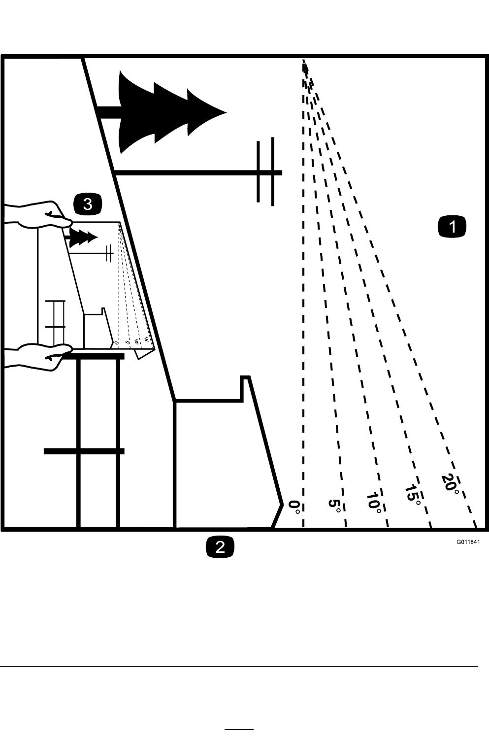
G01 1841
Figure42
Thispagemaybecopiedforpersonaluse.
1.Themaximumslopeyoucansafelyoperatethemachineonis15degrees.Usetheslopeindicatortodeterminethe
degreeofslopeofhillsbeforeoperating.DoNotoperatethismachineonaslopegreaterthan15degrees.Fold
alongtheappropriatelinetomatchtherecommendedslope.
2.Alignthisedgewithaverticalsurface,atree,building,fencepole,etc.
3.Exampleofhowtocompareslopewithfoldededge.
63

MID-MOUNT RIDING ACCESSORIES AND OPTIONS
EXMARK ACCESSORIES AND OPTIONS*
WALK-BEHIND ACCESSORIES AND OPTIONS
GRASS CATCHER
MICRO-MULCH SYSTEM
TURF STRIPER
STANDON
CUSTOM RIDE SEAT SUSPENSION SYSTEM
FULL SUSPENSION SEAT
DECK LIFT ASSIST KIT
HITCH KIT
LIGHT KIT
12V POWER PORT
MICRO-MULCH SYSTEM
OPERATOR CONTROLLED DISCHARGE
SUN SHADE
TRASH CONTAINER
TURF STRIPER
ULTRA VAC COLLECTION SYSTEM
ULTRA VAC QUICK DISPOSAL SYSTEM
OUT-FRONT RIDING ACCESSORIES AND OPTIONS
CUSTOM RIDE SEAT SUSPENSION SYSTEM
DUAL-TAIL WHEEL
FLOOR PAN EXTENDER
HITCH KIT
LIGHT KIT
MICRO-MULCH SYSTEM
ROLL OVER PROTECTION SYSTEM (ROPS)
SNOW BLADE
SNOWBLOWER
SUN SHADE
TRASH CONTAINER
ULTRA VAC COLLECTION SYSTEM
ULTRA VAC QUICK DISPOSAL SYSTEM
WEATHER CAB
*Some accessories and options not available for some models.
PlaceModelNo.andSerialNo.
LabelHere(IncludedintheLiterature
Pack)orFillinBelow
DatePurchased
EngineModelNo.andSpec.No.
ModelNo.EngineSerialNo.(E/No)
SerialNo.
©2012ExmarkMfg.Co.,Inc.
IndustrialParkBox808
Beatrice,NE68310
AllRightsReserved
PartNo.4501-196Rev.A
(402)223-6300
Fax(402)223-5489
PrintedintheUSA
www.exmark.com
