Extreme Networks A3502 ALTITUDE 350-2 ACCESS POINT User Manual SummitWM QS
Extreme Networks ALTITUDE 350-2 ACCESS POINT SummitWM QS
UserManual.wiki
>
Extreme Networks
>
A3502 User Manual
>
QUICK START GUIDE
Contents
1.
USERS MANUAL
2.
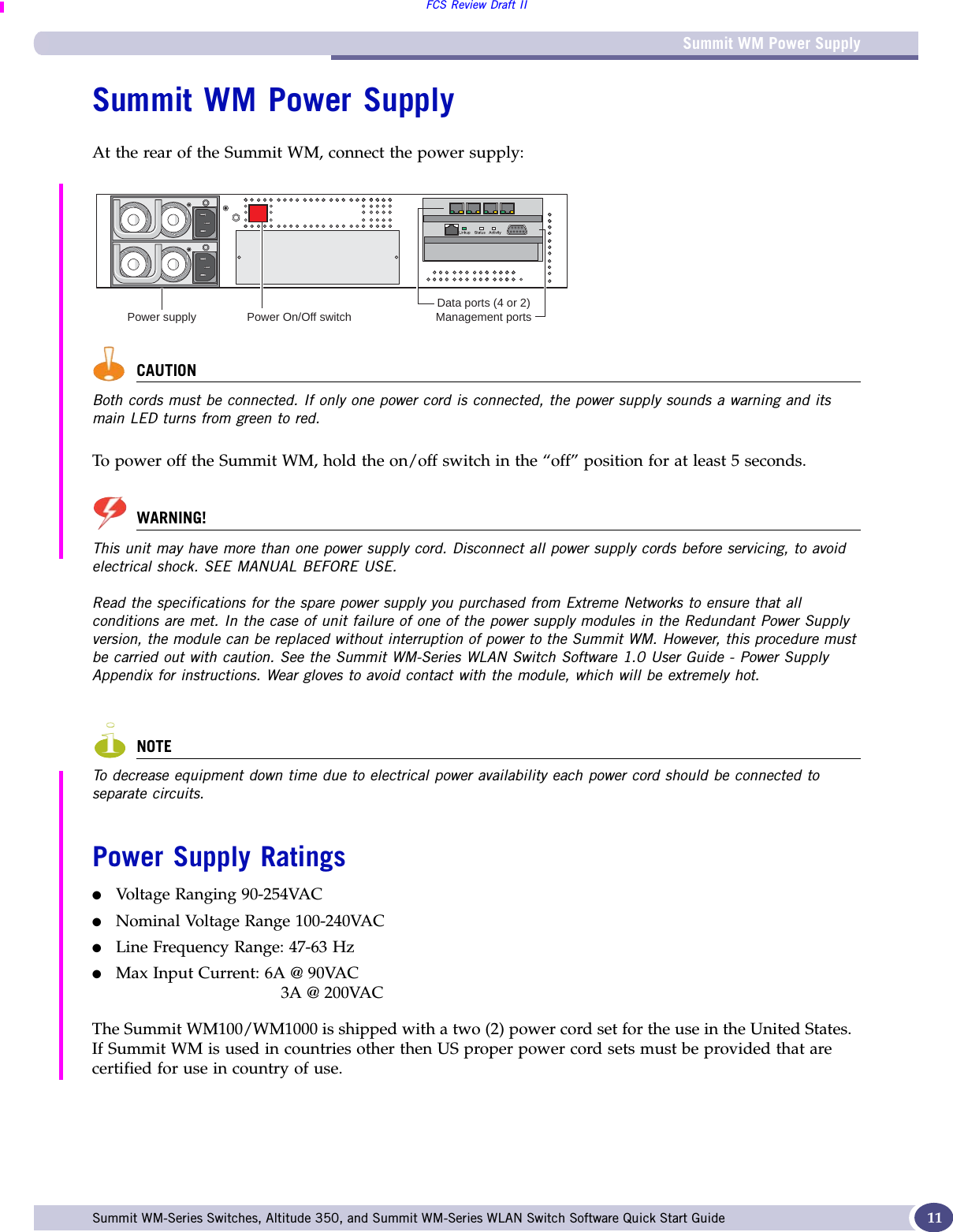
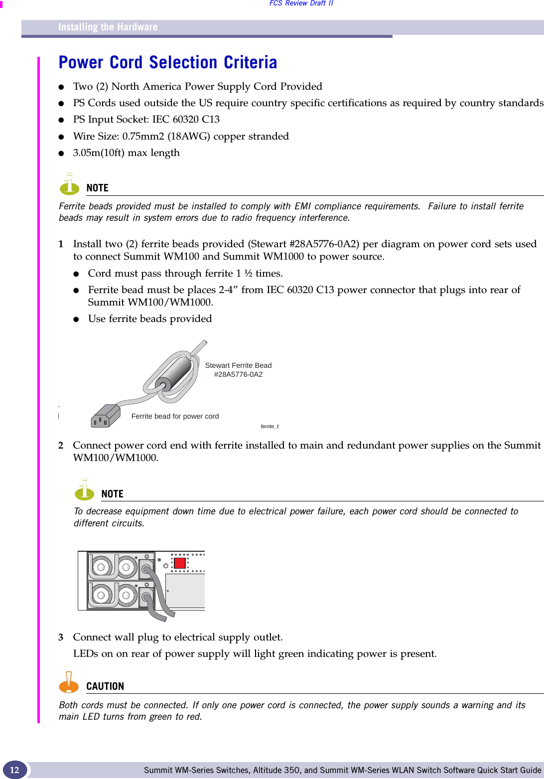
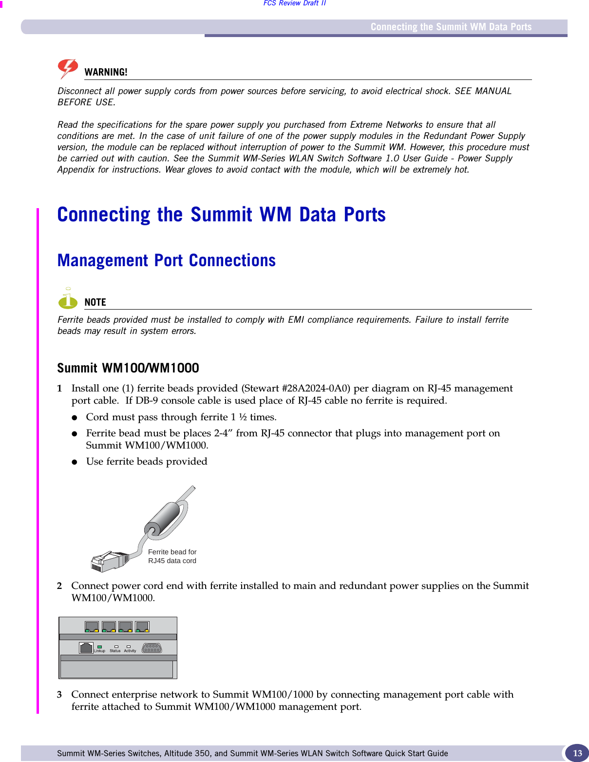
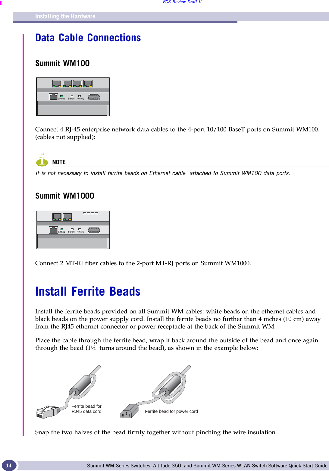
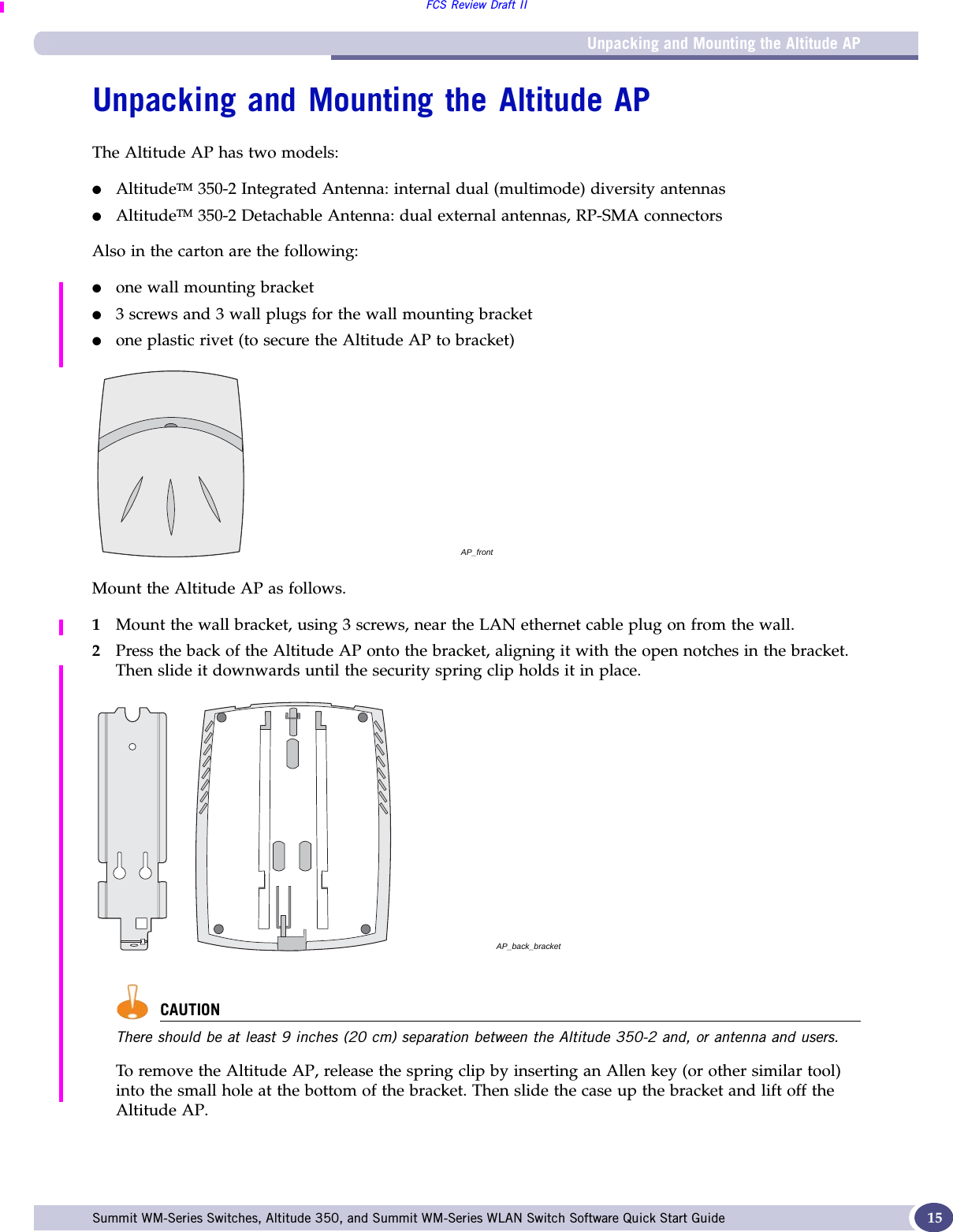
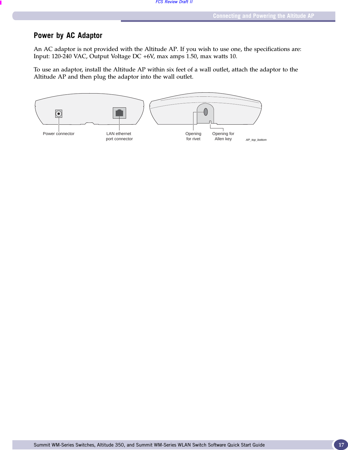
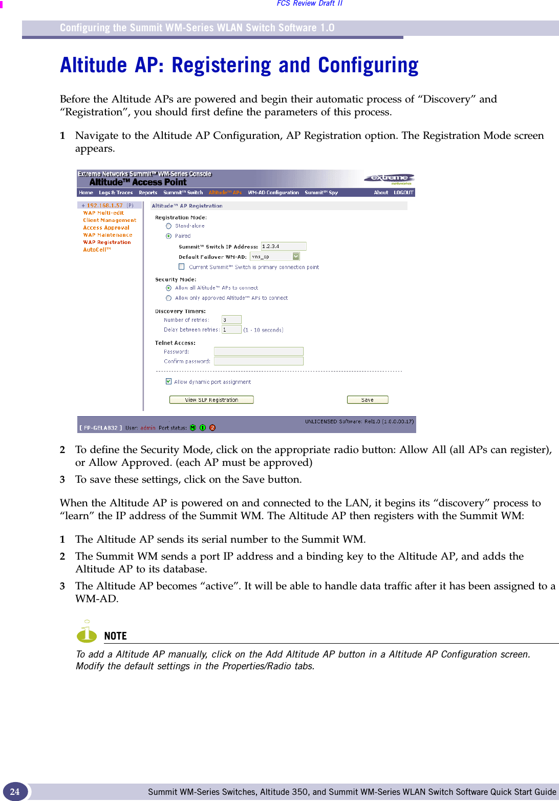
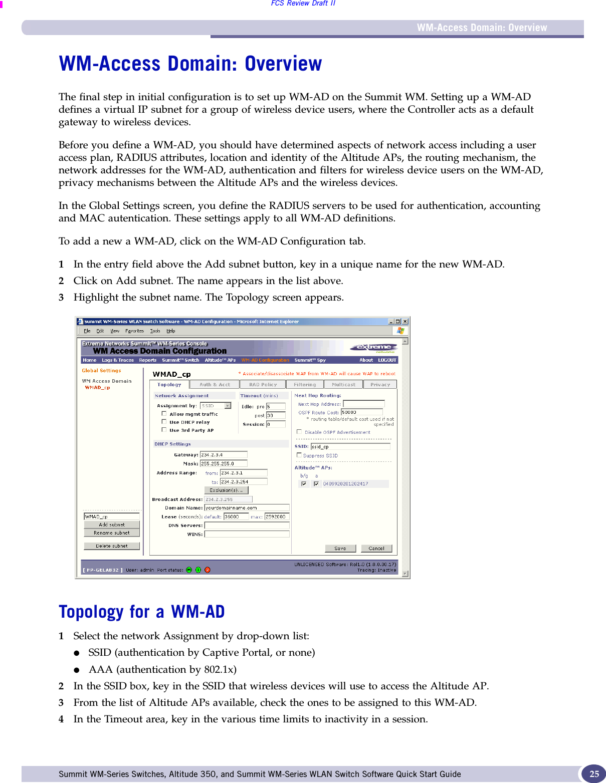
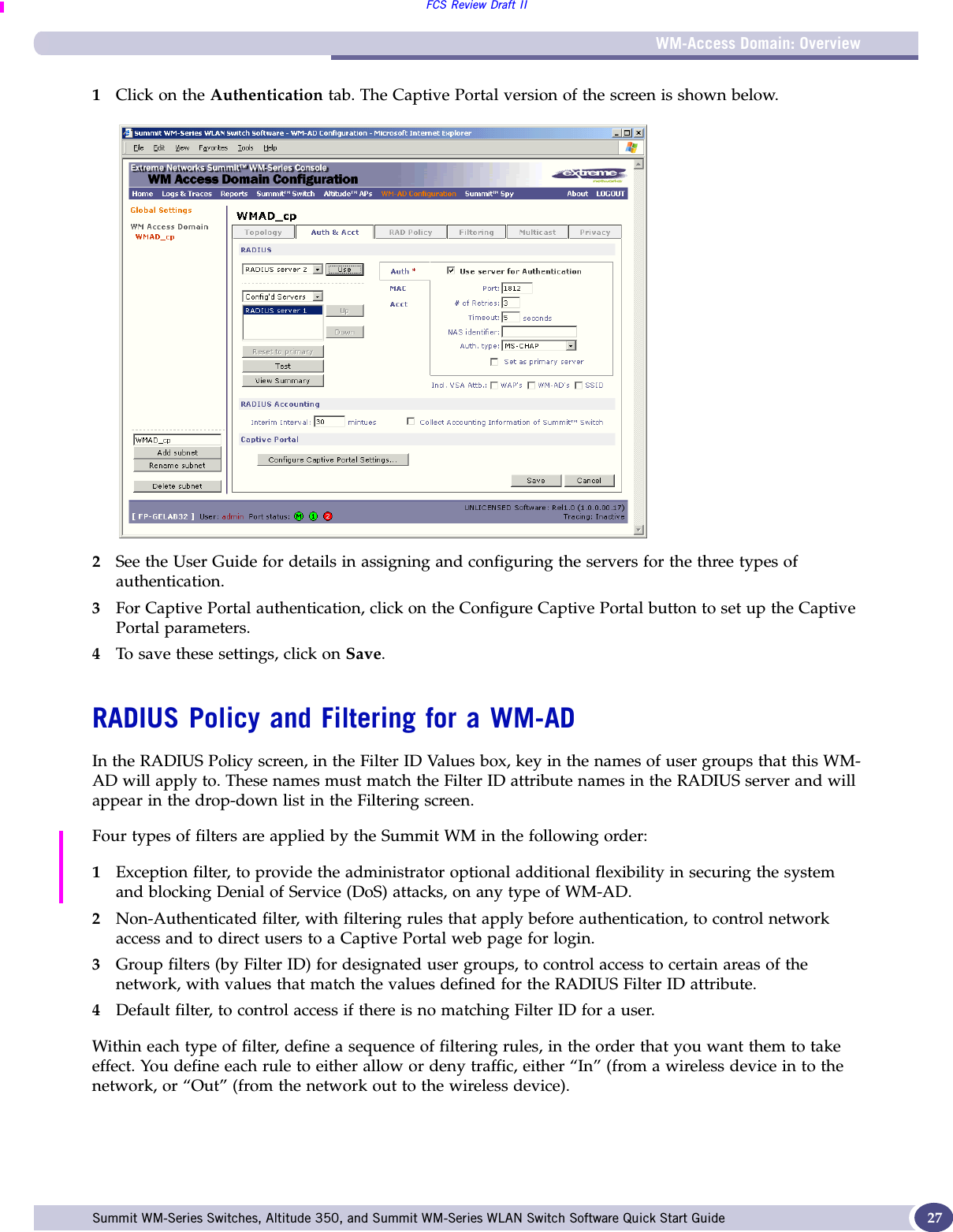
QUICK START GUIDE
QUICK START GUIDE
Navigation menu
Upload a User Manual
Namespaces
Wiki Guide
HTML
PDF
Info
Views
User Manual
Discussion / Help
Navigation