Extreme Networks A3502 ALTITUDE 350-2 ACCESS POINT User Manual SummitWM QS
Extreme Networks ALTITUDE 350-2 ACCESS POINT SummitWM QS
Contents
- 1. USERS MANUAL
- 2. QUICK START GUIDE
QUICK START GUIDE

Extreme Networks, Inc.
3585 Monroe Street
Santa Clara, California 95051
(888) 257-3000
http://www.extremenetworks.com
FCS Review Draft II
Summit WM-Series Switches, Altitude 350, and Summit
WM-Series WLAN Switch Software Quick Start Guide
Published: July 2005
Part number: 100197-00 Rev 01

FCS Review Draft II
Summit WM-Series Switches, Altitude 350, and Summit WM-Series WLAN Switch Software Quick Start Guide
2
Alpine, Altitude, BlackDiamond, EPICenter, Ethernet Everywhere, Extreme Ethernet Everywhere, Extreme
Networks, Extreme Turbodrive, Extreme Velocity, ExtremeWare, ExtremeWorks, GlobalPx Content Director, the Go
Purple Extreme Solution Partners Logo, ServiceWatch, Summit, the Summit7i Logo, and the Color Purple, among
others, are trademarks or registered trademarks of Extreme Networks, Inc. or its subsidiaries in the United States
and other countries. Other names and marks may be the property of their respective owners.
© 2005 Extreme Networks, Inc. All Rights Reserved.
Specifications are subject to change without notice.
The ExtremeWare XOS operating system is based, in part, on the Linux operating system. The machine-readable
copy of the corresponding source code is available for the cost of distribution. Please direct requests to Extreme
Networks for more information at the following address:
Software Licensing Department
3585 Monroe Street
Santa Clara CA 95051
NetWare and Novell are registered trademarks of Novell, Inc. Merit is a registered trademark of Merit Network,
Inc. Solaris and Java are trademarks of Sun Microsystems, Inc. F5, BIG/ip, and 3DNS are registered trademarks of
F5 Networks, Inc. see/IT is a trademark of F5 Networks, Inc.
sFlow® is a registered trademark of InMon Corporation.
All other registered trademarks, trademarks and service marks are property of their respective owners.

FCS Review Draft II
Summit WM-Series Switches, Altitude 350, and Summit WM-Series WLAN Switch Software Quick Start Guide 3
Table of Contents
About this Guide.............................................................................................................................. 5
Who should use this guide ...........................................................................................................5
What is in this guide ...................................................................................................................5
Formatting conventions................................................................................................................5
Safety information.......................................................................................................................6
Dangers................................................................................................................................6
Warnings ..............................................................................................................................6
General Safety Cautions.........................................................................................................7
Chapter 1: Installing the Hardware ................................................................................................... 9
Unpacking the Summit WM .........................................................................................................9
Mounting the Summit WM .........................................................................................................10
Summit WM Power Supply.........................................................................................................11
Power Supply Ratings ..........................................................................................................11
Power Cord Selection Criteria ...............................................................................................12
Connecting the Summit WM Data Ports.......................................................................................13
Management Port Connections .............................................................................................13
Summit WM100/WM1000 .............................................................................................13
Data Cable Connections .......................................................................................................14
Summit WM100 ...........................................................................................................14
Summit WM1000 .........................................................................................................14
Install Ferrite Beads ..................................................................................................................14
Unpacking and Mounting the Altitude AP ....................................................................................15
Connecting and Powering the Altitude AP....................................................................................16
Chapter 2: Configuring the Summit WM-Series WLAN Switch Software 1.0....................................... 19
Configuration stages ..................................................................................................................19
First-Time Setup of the Summit WM ...........................................................................................19
Summit WM Configuration: Product Key......................................................................................22
Summit WM Configuration: Data Port Setup ................................................................................22
Summit WM Configuration: Static Routes....................................................................................23
Altitude AP: Registering and Configuring .....................................................................................24
WM-Access Domain: Overview ....................................................................................................25
Topology for a WM-AD .........................................................................................................25
Network Assignment and Authentication for a WM-AD ............................................................26
RADIUS Policy and Filtering for a WM-AD .............................................................................27
Privacy on a WM-AD ............................................................................................................28
Summit WM-Series WLAN Switch Software 1.0 Ongoing Operations ..............................................28

FCS Review Draft II
Table of Contents
Summit WM-Series Switches, Altitude 350, and Summit WM-Series WLAN Switch Software Quick Start Guide
4

FCS Review Draft II
Summit WM-Series Switches, Altitude 350, and Summit WM-Series WLAN Switch Software Quick Start Guide 5
About this Guide
This guide describes how to set up and perform the initial configuration of the Summit WM-Series
WLAN Switch Software 1.0, the Summit WM, and the Altitude AP. See the Summit WM-Series WLAN
Switch Software 1.0 User Guide for detailed instructions in managing these products.
This guide describes how to set up and perform the initial configuration of the Summit WM-Series
WLAN Switch Software 1.0, the Summit WM, and the Altitude AP. See the Summit WM-Series WLAN
Switch Software 1.0 User Guide for detailed instructions in managing these products.
Who should use this guide
This guide is intended for operators of the Summit WM-Series WLAN Switch Software 1.0. It assumes
expertise in the concepts and configuration of wireless local area networks (WLANs).
WARNING!
Only authorized Extreme Networks service personnel are permitted to service the system. Procedures that should
be performed only by Extreme Networks personnel are clearly identified in this guide.
What is in this guide
This guide contains the following sections:
●Chapter 1 describes how to unpack and set up the Summit WM and Altitude APs.
●Chapter 2 describes the first-time setup of the Summit WM and the Altitude APs on your network. It
provides a brief overview of how to set up WM-AD on the Summit WM to manage network access
by wireless device users.
Formatting conventions
This section describes the text formatting conventions that are used in this manual.
Bold text is used to identify components of the management interface, such as menu items and areas in
pages, as well as the names of text and list boxes.
Italics are used when referring to other documents.
Monospace font is used in code examples and to indicate text that you type.

About this Guide
FCS Review Draft II
Summit WM-Series Switches, Altitude 350, and Summit WM-Series WLAN Switch Software Quick Start Guide
6
NOTE
Notes identify information that is useful but not essential, such as tips or alternative methods for performing a task.
WARNING!
Warnings identify information that is essential. Ignoring a warning can adversely affect the operation of your
equipment or software.
Safety information
WARNING!
Only authorized Extreme Networks service personnel are permitted to service the system. Procedures that should
be performed only by Extreme Networks personnel are clearly identified in this guide.
Changes or modifications made to the Summit WM-Series Switch or the Altitude APs which are not expressly
approved by Extreme and, or the party responsible for compliance upon installation could void the user's authority
to operate the equipment.
Dangers
●Replace power cords or power supply adapters immediately if it shows any signs of damage.
●Replace any damaged safety equipment such as covers, labels or protective cables.
●Use only original accessories, antennas and, or components approved for use with this system.
Failure to observe these instructions may damage the equipment or even violate required safety and
EMC regulations.
Warnings
●Power cords and power adapters must be connected to earth grounded power source.
●Maximum ambient room temperature shall not exceed 40ºC (104ºF)
●Ensure at least 2 inches clearance on all sides for effective ventilation. Do not obstruct the air intake
vent on the front, or the side or rear ventilation grills of the Summit WM.
●The Altitude 350-2 with internal and detachable antenna is intended for indoor use only. Device
must not be connected to a LAN segment exposed to outdoor wiring.
●Ensure that all cables are installed in a manor to avoid strain. Use tie wraps or other strain relief
devices.
●Replacing lithium battery: Battery is not user replaceable. If decided to replace battery replace only
identical battery or equivalent as suggested by battery manufacture. Caution must be taken, there is
a risk of explosion if a lithium battery is not correctly replaced.

Safety information
FCS Review Draft II
Summit WM-Series Switches, Altitude 350, and Summit WM-Series WLAN Switch Software Quick Start Guide 7
General Safety Cautions
●Disconnect all power cords before working near power supplies unless otherwise instructed by a
maintenance procedure.
●Do not attempt to lift objects that you think are too heavy for you.
●When installing in rack, caution should be taken to load heavier devices in lowest portions of rack to
avoid a top-heavy hazard.
●High voltages capable of causing shock are used in this equipment. Check the nominal voltage set
for the equipment as indicated within operating instructions and type plate.
●Be extremely careful when measuring high voltages and when servicing cards, panels, and boards
while the system is powered on.
●Only use tools and equipment that are in perfect condition. Do not use equipment with visible
damage.
●Protecting electrostatically sensitive devices (ESD): To protect electrostatically sensitive devices (ESD)
always wear a wristband before carrying out any work on PC boards and modules. Transport PC
boards only in electrostatic packaging. Always place PC boards on a grounded surface before
working on them.
●Laying cables: Lay cables so as to prevent any risk of them being damaged or causing accidents,
such as tripping.

About this Guide
FCS Review Draft II
Summit WM-Series Switches, Altitude 350, and Summit WM-Series WLAN Switch Software Quick Start Guide
8
FCS Review Draft II
Summit WM-Series Switches, Altitude 350, and Summit WM-Series WLAN Switch Software Quick Start Guide 9
1Installing the Hardware
Unpacking the Summit WM
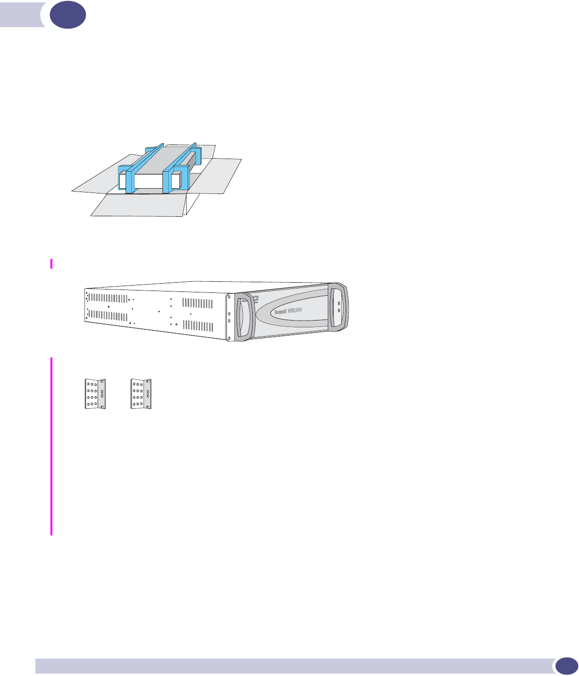
Lift the Summit WM, in its protective foam casing, straight up out of the carton. Lay it on a flat surface.
Slide off the foam packing.
The carton contains the following:
●One Summit WM
●Mounting brackets: one pair
●Two power cords for use in US only.
●Two ferrite beads Stewart #28A5776-0A2 required for for use on power cord sets
(See installation instructions).
●One ferrite bead Stewart #28A2024-0A0 required for for use on management port.
(See installation instructions).
●Screws: eight 6-32 X 3/8 countersunk machine screws
●One crossover ethernet cable (for installation)
●Summit WM-Series WLAN Switch Software 1.0 User Guide (CD)
Installing the Hardware
FCS Review Draft II
Summit WM-Series Switches, Altitude 350, and Summit WM-Series WLAN Switch Software Quick Start Guide
10
Mounting the Summit WM
Rack-Mount
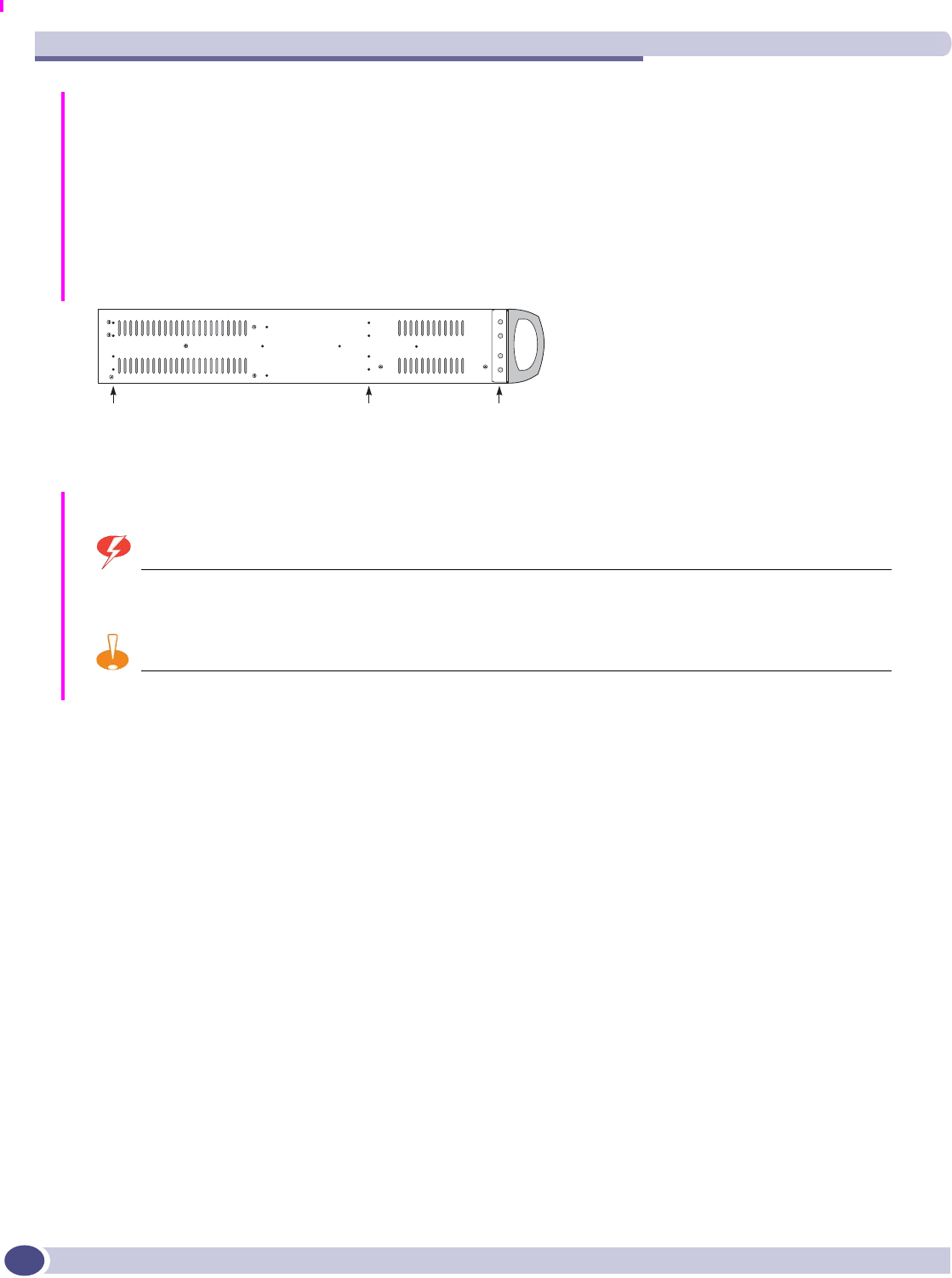
The Summit WM has three sets of four holes on each side, in three positions: front, center and rear.
Attach the mounting brackets to the Summit WM in appropriate position for the type of rack to be
used. Attach the brackets to the rack.
Table Mount
Ensure at least 2 inches clearance on all sides for effective ventilation.
WARNING!
Do not obstruct the air intake vent on the front, or the side or rear ventilation grills of the Summit WM.
CAUTION
When installing the unit in a rack, load the heaviest devices in lowest portions of rack to avoid a top-heavy hazard.
Rear mount Center mount Front mount

Summit WM Power Supply
FCS Review Draft II
Summit WM-Series Switches, Altitude 350, and Summit WM-Series WLAN Switch Software Quick Start Guide 11
Summit WM Power Supply
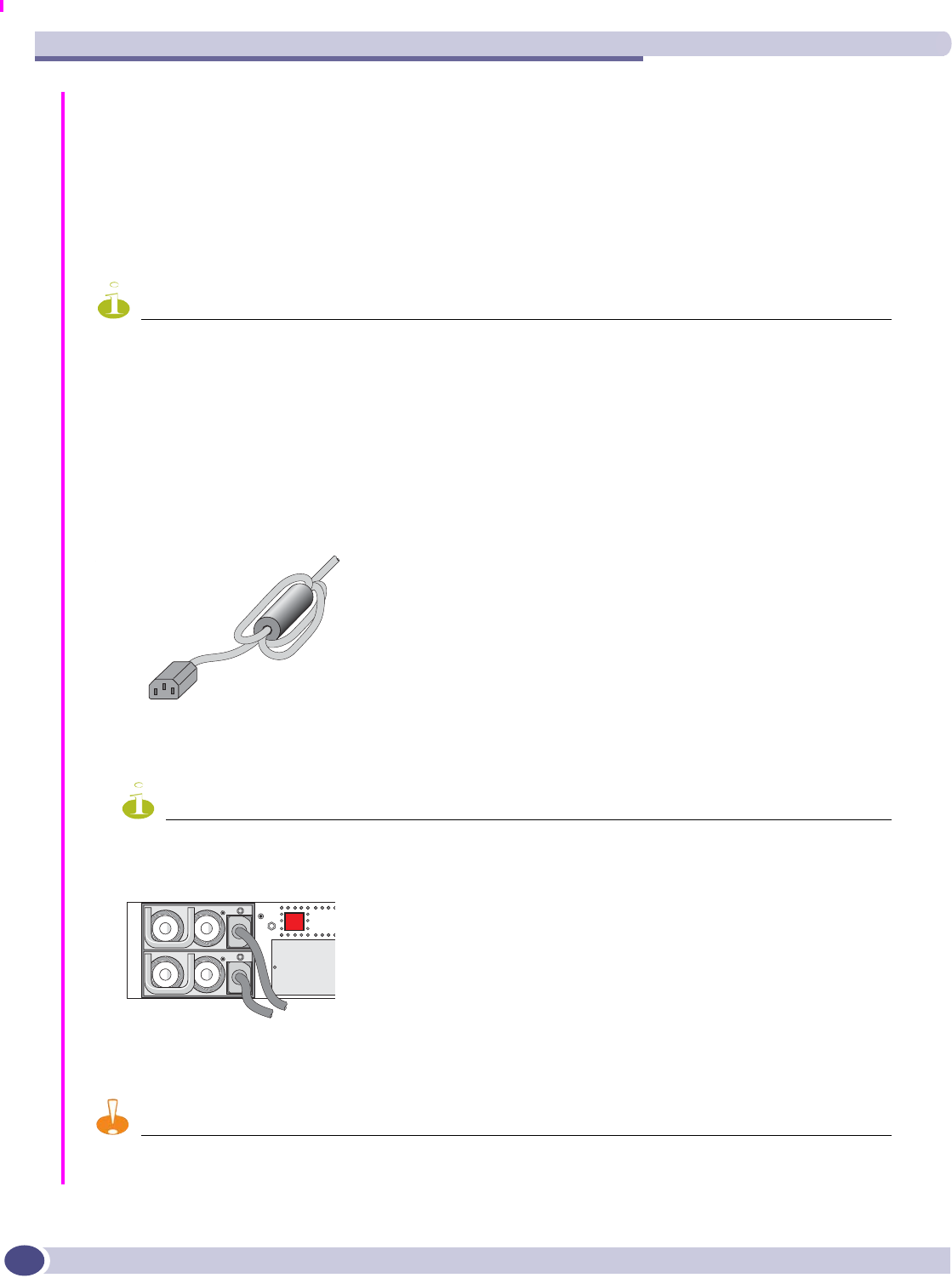
At the rear of the Summit WM, connect the power supply:
CAUTION
Both cords must be connected. If only one power cord is connected, the power supply sounds a warning and its
main LED turns from green to red.
To power off the Summit WM, hold the on/off switch in the “off” position for at least 5 seconds.
WARNING!
This unit may have more than one power supply cord. Disconnect all power supply cords before servicing, to avoid
electrical shock. SEE MANUAL BEFORE USE.
Read the specifications for the spare power supply you purchased from Extreme Networks to ensure that all
conditions are met. In the case of unit failure of one of the power supply modules in the Redundant Power Supply
version, the module can be replaced without interruption of power to the Summit WM. However, this procedure must
be carried out with caution. See the Summit WM-Series WLAN Switch Software 1.0 User Guide - Power Supply
Appendix for instructions. Wear gloves to avoid contact with the module, which will be extremely hot.
NOTE
To decrease equipment down time due to electrical power availability each power cord should be connected to
separate circuits.
Power Supply Ratings
●Voltage Ranging 90-254VAC
●Nominal Voltage Range 100-240VAC
●Line Frequency Range: 47-63 Hz
●Max Input Current: 6A @ 90VAC
3A @ 200VAC
The Summit WM100/WM1000 is shipped with a two (2) power cord set for the use in the United States.
If Summit WM is used in countries other then US proper power cord sets must be provided that are
certified for use in country of use.
Power supply Power On/Off switch
Data ports (4 or 2)
Management ports
Installing the Hardware
FCS Review Draft II
Summit WM-Series Switches, Altitude 350, and Summit WM-Series WLAN Switch Software Quick Start Guide
12
Power Cord Selection Criteria
●Two (2) North America Power Supply Cord Provided
●PS Cords used outside the US require country specific certifications as required by country standards
●PS Input Socket: IEC 60320 C13
●Wire Size: 0.75mm2 (18AWG) copper stranded
●3.05m(10ft) max length
NOTE
Ferrite beads provided must be installed to comply with EMI compliance requirements. Failure to install ferrite
beads may result in system errors due to radio frequency interference.
1Install two (2) ferrite beads provided (Stewart #28A5776-0A2) per diagram on power cord sets used
to connect Summit WM100 and Summit WM1000 to power source.
●Cord must pass through ferrite 1 ½ times.
●Ferrite bead must be places 2-4” from IEC 60320 C13 power connector that plugs into rear of
Summit WM100/WM1000.
●Use ferrite beads provided
2Connect power cord end with ferrite installed to main and redundant power supplies on the Summit
WM100/WM1000.
NOTE
To decrease equipment down time due to electrical power failure, each power cord should be connected to
different circuits.
3Connect wall plug to electrical supply outlet.
LEDs on on rear of power supply will light green indicating power is present.
CAUTION
Both cords must be connected. If only one power cord is connected, the power supply sounds a warning and its
main LED turns from green to red.
ferrite_
b
r
d
Ferrite bead for power cord
Stewart Ferrite Bead
#28A5776-0A2

Connecting the Summit WM Data Ports
FCS Review Draft II
Summit WM-Series Switches, Altitude 350, and Summit WM-Series WLAN Switch Software Quick Start Guide 13
WARNING!
Disconnect all power supply cords from power sources before servicing, to avoid electrical shock. SEE MANUAL
BEFORE USE.
Read the specifications for the spare power supply you purchased from Extreme Networks to ensure that all
conditions are met. In the case of unit failure of one of the power supply modules in the Redundant Power Supply
version, the module can be replaced without interruption of power to the Summit WM. However, this procedure must
be carried out with caution. See the Summit WM-Series WLAN Switch Software 1.0 User Guide - Power Supply
Appendix for instructions. Wear gloves to avoid contact with the module, which will be extremely hot.
Connecting the Summit WM Data Ports
Management Port Connections
NOTE
Ferrite beads provided must be installed to comply with EMI compliance requirements. Failure to install ferrite
beads may result in system errors.
Summit WM100/WM1000
1Install one (1) ferrite beads provided (Stewart #28A2024-0A0) per diagram on RJ-45 management
port cable. If DB-9 console cable is used place of RJ-45 cable no ferrite is required.
●Cord must pass through ferrite 1 ½ times.
●Ferrite bead must be places 2-4” from RJ-45 connector that plugs into management port on
Summit WM100/WM1000.
●Use ferrite beads provided
2Connect power cord end with ferrite installed to main and redundant power supplies on the Summit
WM100/WM1000.
3Connect enterprise network to Summit WM100/1000 by connecting management port cable with
ferrite attached to Summit WM100/WM1000 management port.
Ferrite bead for
RJ45 data cord
Installing the Hardware
FCS Review Draft II
Summit WM-Series Switches, Altitude 350, and Summit WM-Series WLAN Switch Software Quick Start Guide
14
Data Cable Connections
Summit WM100
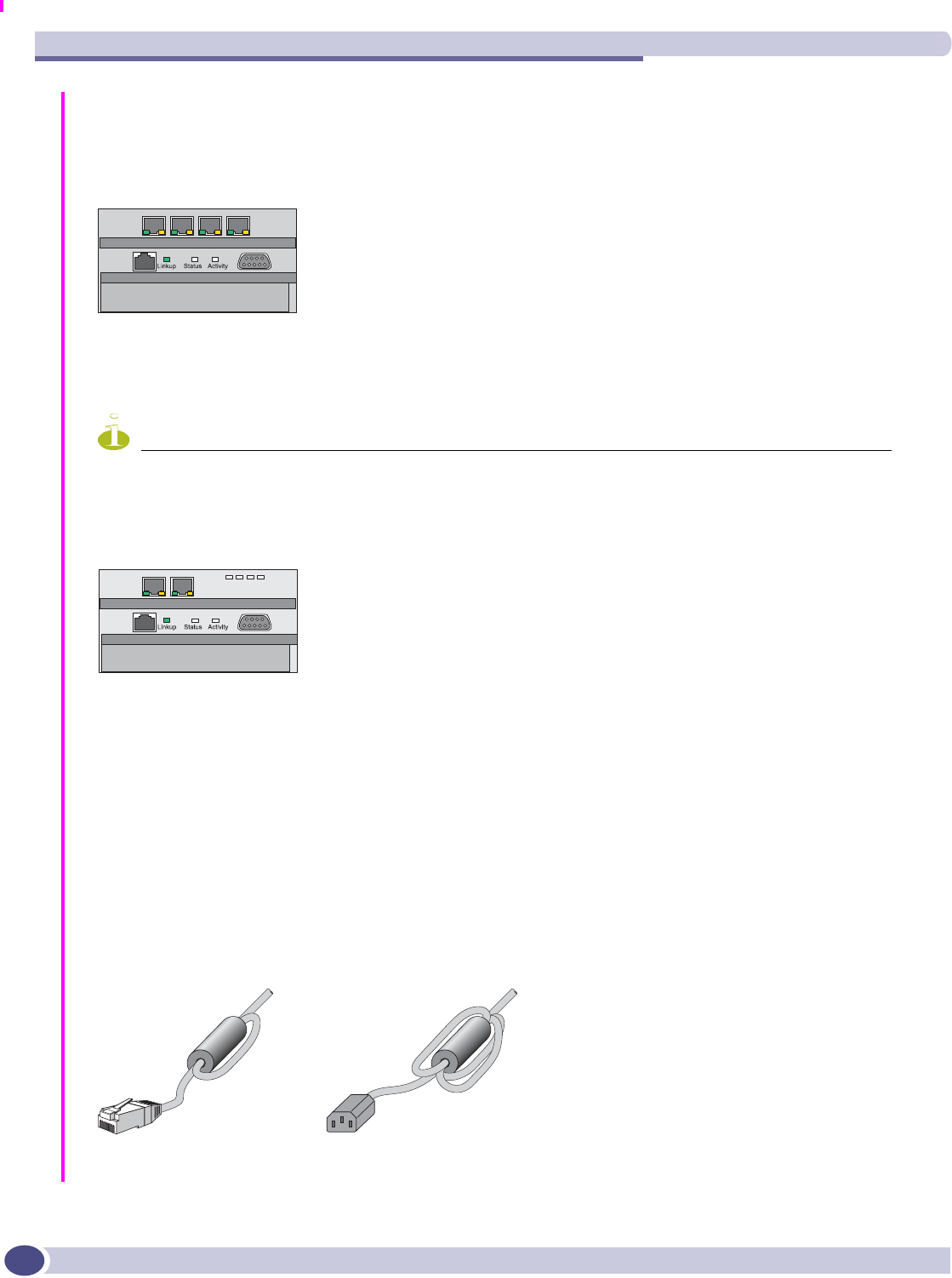
Connect 4 RJ-45 enterprise network data cables to the 4-port 10/100 BaseT ports on Summit WM100.
(cables not supplied):
NOTE
It is not necessary to install ferrite beads on Ethernet cable attached to Summit WM100 data ports.
Summit WM1000
Connect 2 MT-RJ fiber cables to the 2-port MT-RJ ports on Summit WM1000.
Install Ferrite Beads
Install the ferrite beads provided on all Summit WM cables: white beads on the ethernet cables and
black beads on the power supply cord. Install the ferrite beads no further than 4 inches (10 cm) away
from the RJ45 ethernet connector or power receptacle at the back of the Summit WM.
Place the cable through the ferrite bead, wrap it back around the outside of the bead and once again
through the bead (1½ turns around the bead), as shown in the example below:
Snap the two halves of the bead firmly together without pinching the wire insulation.
Ferrite bead for
RJ45 data cord Ferrite bead for power cord
Unpacking and Mounting the Altitude AP
FCS Review Draft II
Summit WM-Series Switches, Altitude 350, and Summit WM-Series WLAN Switch Software Quick Start Guide 15
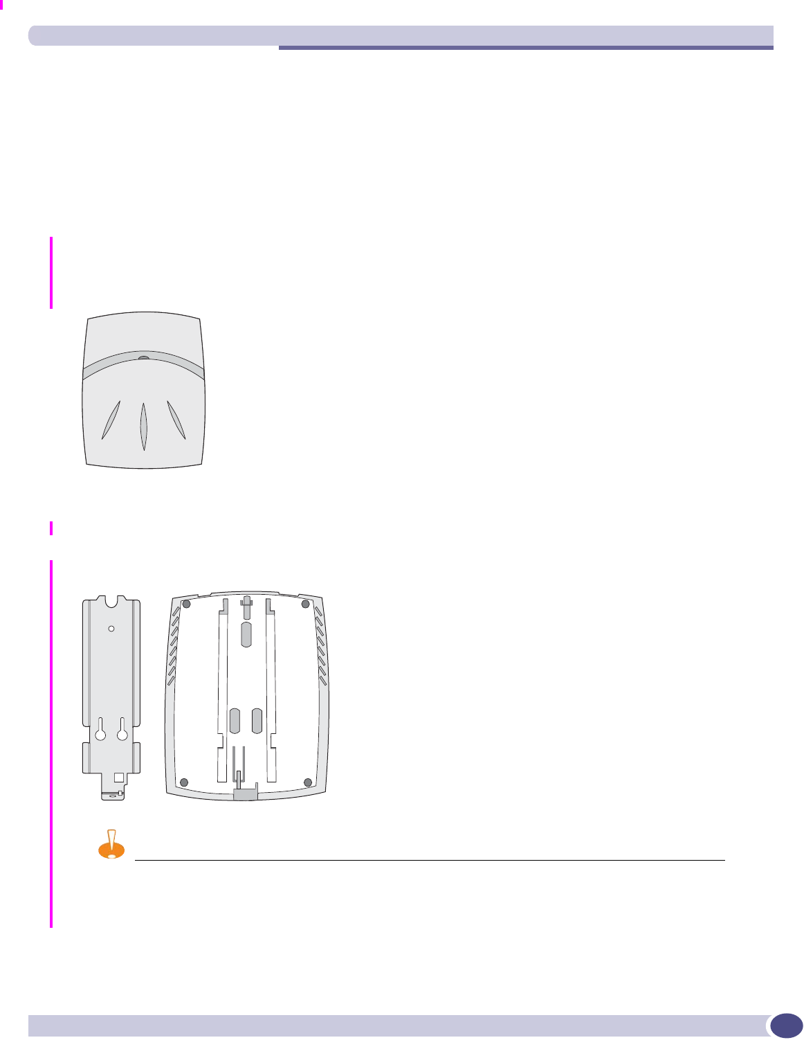
Unpacking and Mounting the Altitude AP
The Altitude AP has two models:
●AltitudeTM 350-2 Integrated Antenna: internal dual (multimode) diversity antennas
●AltitudeTM 350-2 Detachable Antenna: dual external antennas, RP-SMA connectors
Also in the carton are the following:
●one wall mounting bracket
●3 screws and 3 wall plugs for the wall mounting bracket
●one plastic rivet (to secure the Altitude AP to bracket)
Mount the Altitude AP as follows.
1Mount the wall bracket, using 3 screws, near the LAN ethernet cable plug on from the wall.
2Press the back of the Altitude AP onto the bracket, aligning it with the open notches in the bracket.
Then slide it downwards until the security spring clip holds it in place.
CAUTION
There should be at least 9 inches (20 cm) separation between the Altitude 350-2 and, or antenna and users.
To remove the Altitude AP, release the spring clip by inserting an Allen key (or other similar tool)
into the small hole at the bottom of the bracket. Then slide the case up the bracket and lift off the
Altitude AP.
AP_front
AP_back_bracket

Installing the Hardware
FCS Review Draft II
Summit WM-Series Switches, Altitude 350, and Summit WM-Series WLAN Switch Software Quick Start Guide
16
3Using a screwdriver, insert the plastic rivet through the hole at the bottom of the bracket and into
the Altitude AP case. This locks the case to the bracket. To remove the Altitude AP, use a
screwdriver to take out the rivet.
WARNING!
For installations that use Receive diversity (the default) the antennas should be pointed in the same direction.
For installations that do NOT use Receive diversity or for those that split the 802.11a and 802.11b/g radio onto
different physical ports, then the antennas can be pointed in whatever direction is desired.
Connecting and Powering the Altitude AP
WARNING!
The Altitude 350-2 with internal and detachable antenna is intended for indoor use only. The device must not be
connected to a LAN segment exposed to outdoor wiring. Ensure that all cables are installed to avoid strain. Replace
the power supply adaptor immediately, if it shows any signs of damage.
NOTE
The Altitude 350-2 access point will automatically discontinue transmission in case of either absence of information
to transmit (no frames transmitted through Ethernet) or operational failure.
Powering up the Altitude AP initiates its automatic discovery and registration process with the Summit
WM, The parameters for this process should be set in the user interface (AP Registration) (see Chapter
4, Discovery and registration: Altitude AP registration settings” in the Summit WM-Series WLAN
Switch Software 1.0 User Guide).
Connect and power up the Altitude AP in one of three ways:
CAUTION
The Altitude 350-2 shall be powered by UL approved limited power source adapter or UL approved limited power
source power over ethernet (PoE)
Power Over Ethernet (PoE)
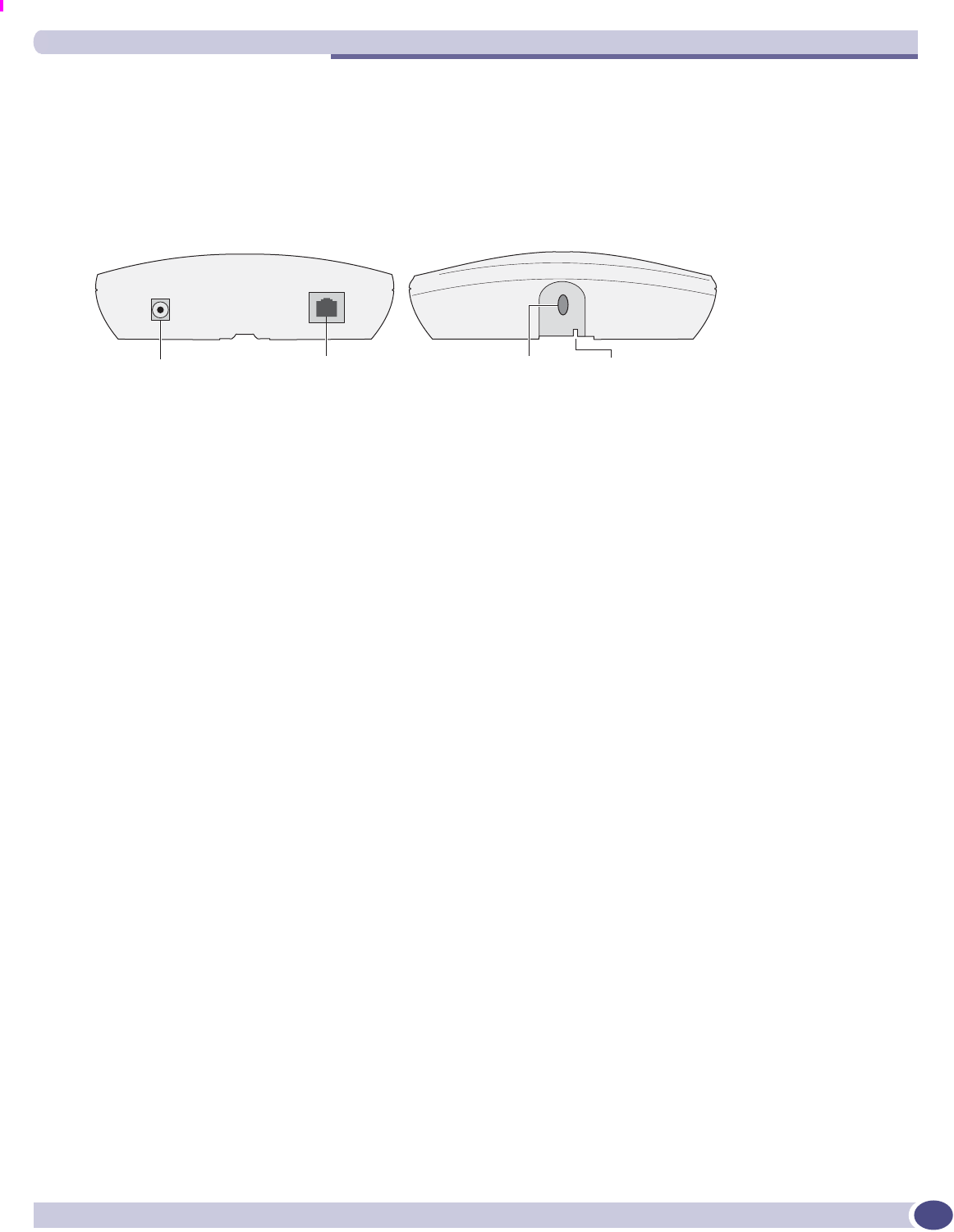
If your network is already set up with PoE (802.3af compliant), attach the LAN ethernet cable to the
RJ45 ethernet connector in the top of the Altitude AP.
Power Over Ethernet: Adding PoE Injector
If your network is not set up with PoE, you can provide power to the ethernet cable with a PoE injector.
The PoE injector must be 802.3af compliant. The PoE injector is not provided with the Altitude AP.
Connecting and Powering the Altitude AP
FCS Review Draft II
Summit WM-Series Switches, Altitude 350, and Summit WM-Series WLAN Switch Software Quick Start Guide 17
Power by AC Adaptor
An AC adaptor is not provided with the Altitude AP. If you wish to use one, the specifications are:
Input: 120-240 VAC, Output Voltage DC +6V, max amps 1.50, max watts 10.
To use an adaptor, install the Altitude AP within six feet of a wall outlet, attach the adaptor to the
Altitude AP and then plug the adaptor into the wall outlet.
AP_top_bottom
Power connector LAN ethernet
port connector
Opening for
Allen key
Opening
for rivet

Installing the Hardware
FCS Review Draft II
Summit WM-Series Switches, Altitude 350, and Summit WM-Series WLAN Switch Software Quick Start Guide
18

FCS Review Draft II
Summit WM-Series Switches, Altitude 350, and Summit WM-Series WLAN Switch Software Quick Start Guide 19
2Configuring the Summit WM-Series WLAN
Switch Software 1.0
Configuration stages
There are six stages in setting up and configuring the Summit WM and Altitude APs:
1First-Time Setup: Perform “First-Time Setup” of the Summit WM on the physical network by
configuring the Management Port.
2Product Key: Apply a Product Key file, for licensing purposes. If no Product Key is enabled, the
Summit WM functions with all features enabled in demonstration mode.
3Data Port Setup: Set up the Summit WM on the physical network by configuring the physical data
ports.
4Routing Setup: For any port defined as a “router port”, configure static routes and OSPF parameters
(if appropriate on the network).
5Altitude AP Initial Setup: Determine the Altitude AP registration mode, then connect and power on
the APs (they now discover and register with the Controller).
6WM-AD Setup: Set up one or more WM-AD, using the WM-AD Configuration capability on the
Summit WM. Select the Altitude APs on the WM-AD. Then configure authentication, accounting,
filtering, multicast and privacy.
First-Time Setup of the Summit WM
Before you can connect the Summit WM to the enterprise network, you must change the IP address of
the Summit WM management port from its factory default to the IP address suitable for your enterprise
network. Access the Summit WM by one of two methods:
●Use a device supporting VT100 emulation, attached to the DB9 serial port (COM1 port) of the
Summit WM via a cross-over (null modem) cable. Use the Command Line Interface (CLI)
commands.
●Use a laptop computer running a web browser. Connect the supplied cross-over ethernet cable
between the laptop and management ethernet port of the Summit WM. Follow the steps below.
1Statically assign an unused IP address in the 192.168.10.0/24 subnet for the ethernet port of the PC
(such as, 192.168.10.205).
2Run the web browser on the laptop.
Configuring the Summit WM-Series WLAN Switch Software 1.0
FCS Review Draft II
Summit WM-Series Switches, Altitude 350, and Summit WM-Series WLAN Switch Software Quick Start Guide
20
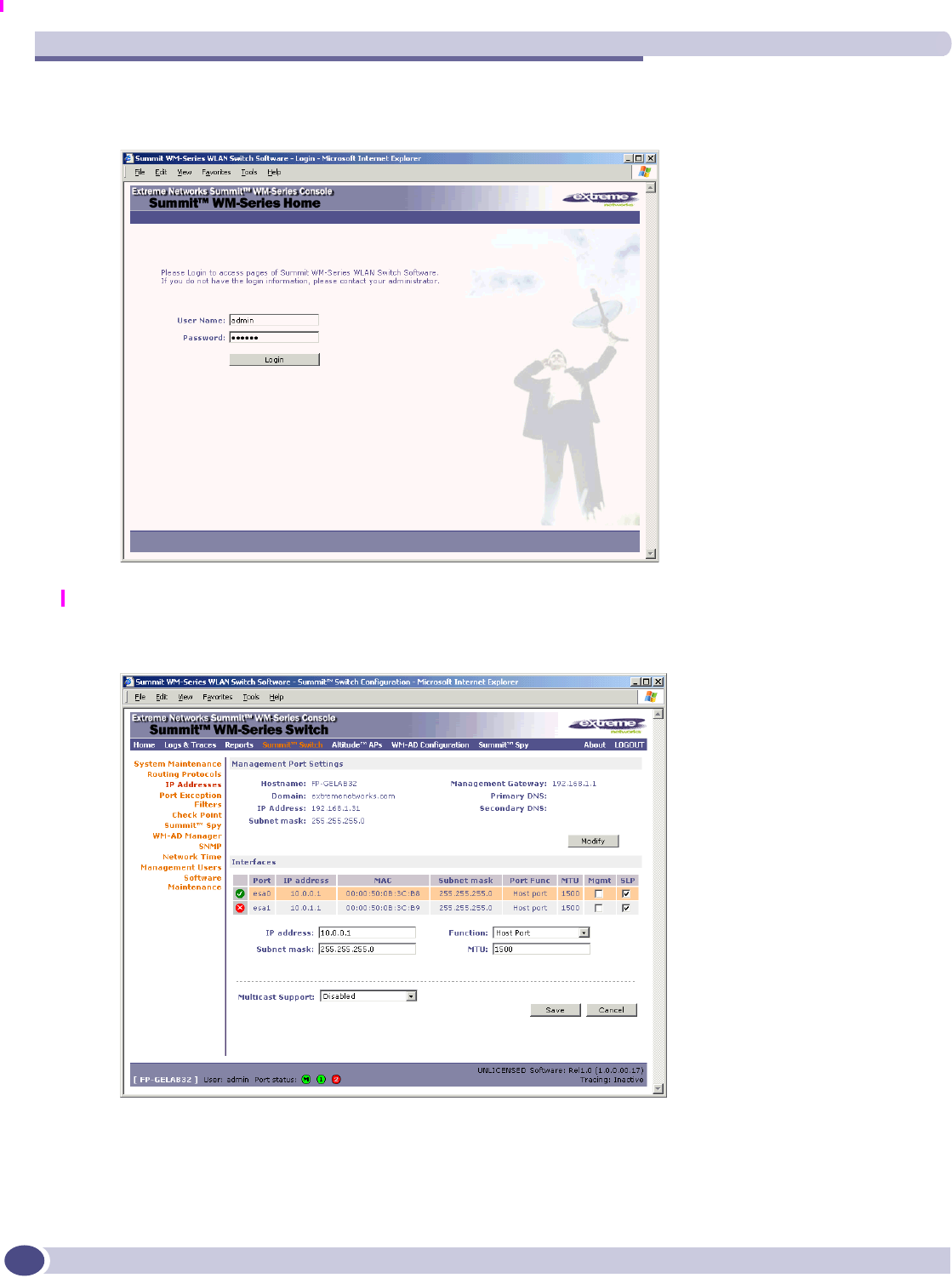
3Point the browser to the URL https://192.168.10.1:5825. This launches the web-based GUI on the
Summit WM.
4Log in as User Name: admin, Password is blank.
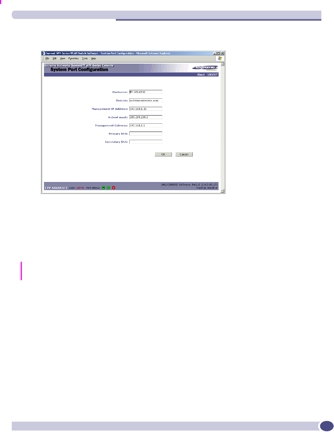
5Navigate to the Summit WM Configuration screen, IP Addresses option. This screen first displays
the factory defaults.
First-Time Setup of the Summit WM
FCS Review Draft II
Summit WM-Series Switches, Altitude 350, and Summit WM-Series WLAN Switch Software Quick Start Guide 21
6To modify Management Port Settings, click the Modify button. The System Port Configuration screen
appears.
7Key in the new IP address of the Summit WM’s management port, as appropriate to the enterprise
network.
8Key in the default gateway of the network, as well as the network name servers.
9Click OK to return to the Summit WM Configuration screen.
10 Click on the Save button, to save the port changes.
The web connection between the laptop and the Summit WM is now lost, because their IP addresses are
now on different networks. Before you can continue configuring the Summit WM, you must establish its
presence on the enterprise network.
To add the Summit WM to your enterprise network:
1Disconnect the laptop from the Summit WM Management Port.
2Connect the Summit WM Management Port to the enterprise ethernet LAN.
3Reboot the Summit WM.
Now you will be able to launch the Summit WM-Series WLAN Switch Software 1.0 GUI again.

Configuring the Summit WM-Series WLAN Switch Software 1.0
FCS Review Draft II
Summit WM-Series Switches, Altitude 350, and Summit WM-Series WLAN Switch Software Quick Start Guide
22
Summit WM Configuration: Product Key
Click on the Summit WM tab, Software Maintenance option, SWM Product Keys tab. The Product Keys
screen appears. Enter your Product Key information, as proof of purchase and to access advanced
features.
Summit WM Configuration: Data Port Setup
1Navigate to the Summit WM Configuration screen, IP Addresses option. The lower portion of the
screen displays the Interfaces, either the four ethernet ports for the SummitTM WM100, or the two
ports for the SummitTM WM1000.
2For each physical port, key in:
3For the highlighted port, select its function and mode:
NOTE
Configure at least one port as a “Router” Port, so that static routes and/or OSPF routing can be defined for the
Summit WM.
4For the highlighted port, click the Mgmt checkbox on to allow Management Traffic on this port.
5For the highlighted port, click the SLP checkbox on to allow SLP protocol on this port for Altitude
AP discovery and registration.
NOTE
For the implications of the SLP and Mgmt options, see Port-Level Filtering in the Summit WM-Series WLAN
Switch Software 1.0 User Guide.
6To save the port configuration, click Save.
To cancel the entries without saving, click Cancel.
Host Port: This port type is the factory default. Define as “Host Port” any port to which only Altitude
APs are connected. Normal IP forwarding and dynamic routing are disabled.
Third-Party AP: Define as “Third-Party AP” any port to which you will connect only third-party access
points, for Summit WM to control. Do not connect Altitude APs to this type of port.
Router: Define as “Router Port” a port that you wish to connect to an upstream next-hop router in the
network. Dynamic routing protocol (such as OSPF) can be turned on for this port type. Altitude APs
can be attached to a “Router” port.
IP address IP Address of the physical ethernet port
Subnet mask For the IP address, the appropriate subnet mask to separate the network
portion from the host portion of the address
MTU Maximum Transmission Unit (maximum packet size for this port). Default
setting is 1500.
Function Select port type from the drop-down list: Host Port, 3rd Party AP, Router
Summit WM Configuration: Static Routes
FCS Review Draft II
Summit WM-Series Switches, Altitude 350, and Summit WM-Series WLAN Switch Software Quick Start Guide 23
Summit WM Configuration: Static Routes
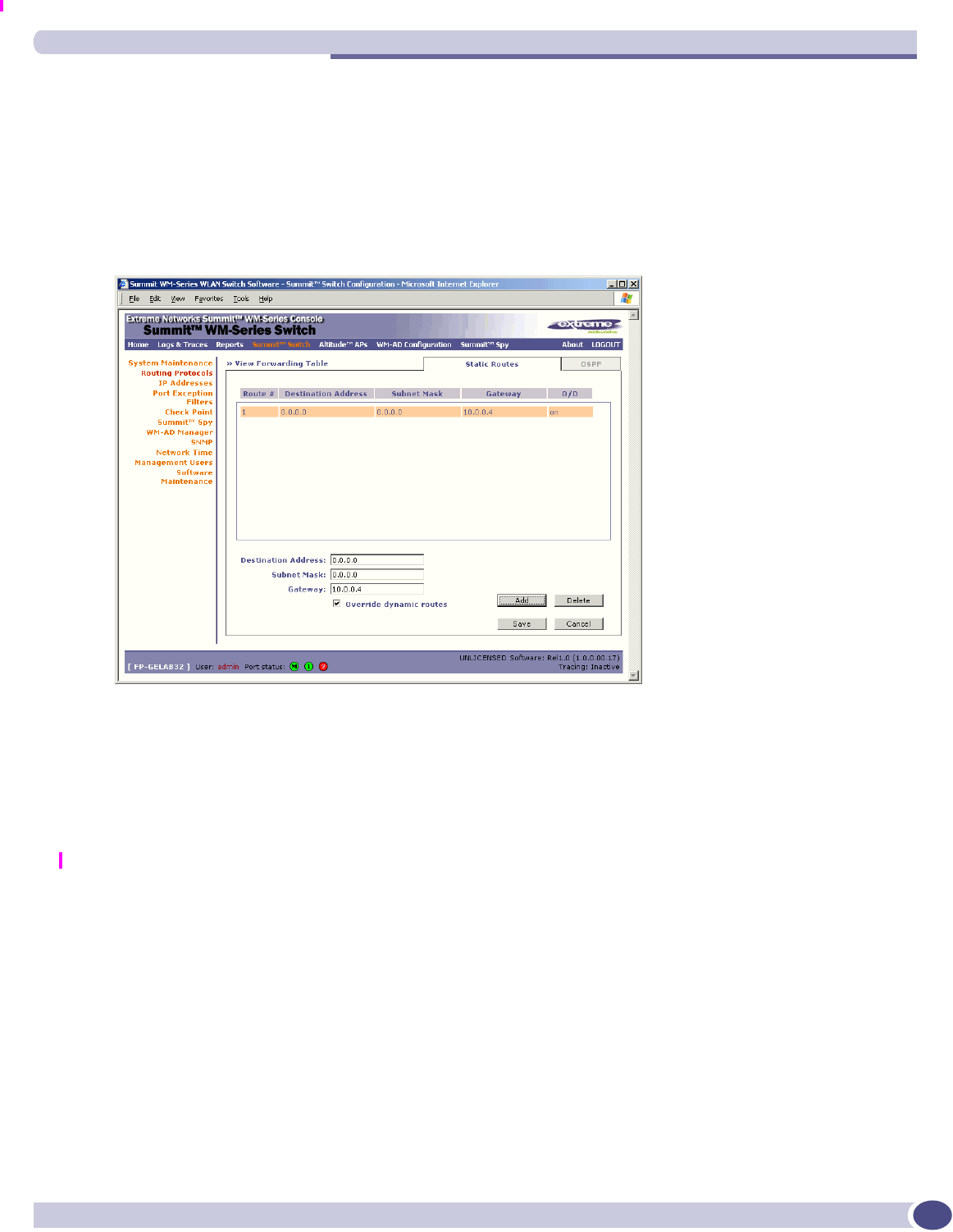
If you configure one data port as a “Router” port, you can define a default route to the enterprise
network, with a static route or with OSPF protocol (Open Shortest Path First). This enables the Summit
WM to forward wireless packets to the remainder of the network.
1Navigate to the Summit WM Routing Protocols option. Then click the Static Routes tab. The Static
Routes screen appears.
2To add a new route, click in the Destination Address field, and key in the destination IP address that
this static route applies to. To define a default static route for any unknown address not in the
routing table, key in 0.0.0.0
3Key in the Subnet Mask for the IP address. For the default static route for any unknown address, key
in 0.0.0.0.
4Select an outbound destination for the packets, in one of two ways:
Click on the Gateway radio button, and key in the IP address of the next hop between the Summit
WM and the packet's ultimate destination, or
Click on the Interface button, and select a port from the list.
5The Override dynamic routes checkbox is on by default, giving priority to static routes defined here
over OSPF learned routes. For dynamic routing, click the checkbox off.
6Click on the Add button. The new route appears in the list.
7Click on Save to update the routing table on the Summit WM.
To set up OSPF routing, see the Summit WM User Guide.
Configuring the Summit WM-Series WLAN Switch Software 1.0
FCS Review Draft II
Summit WM-Series Switches, Altitude 350, and Summit WM-Series WLAN Switch Software Quick Start Guide
24
Altitude AP: Registering and Configuring
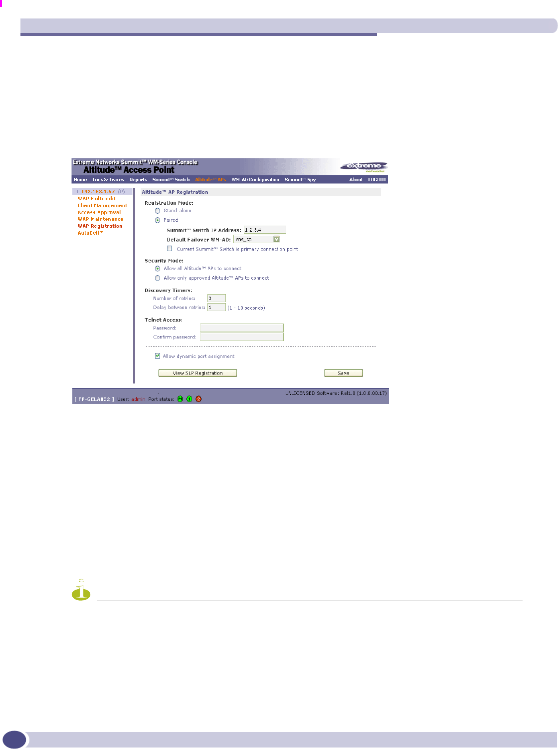
Before the Altitude APs are powered and begin their automatic process of “Discovery” and
“Registration”, you should first define the parameters of this process.
1Navigate to the Altitude AP Configuration, AP Registration option. The Registration Mode screen
appears.
2To define the Security Mode, click on the appropriate radio button: Allow All (all APs can register),
or Allow Approved. (each AP must be approved)
3To save these settings, click on the Save button.
When the Altitude AP is powered on and connected to the LAN, it begins its “discovery” process to
“learn” the IP address of the Summit WM. The Altitude AP then registers with the Summit WM:
1The Altitude AP sends its serial number to the Summit WM.
2The Summit WM sends a port IP address and a binding key to the Altitude AP, and adds the
Altitude AP to its database.
3The Altitude AP becomes “active”. It will be able to handle data traffic after it has been assigned to a
WM-AD.
NOTE
To add a Altitude AP manually, click on the Add Altitude AP button in a Altitude AP Configuration screen.
Modify the default settings in the Properties/Radio tabs.
WM-Access Domain: Overview
FCS Review Draft II
Summit WM-Series Switches, Altitude 350, and Summit WM-Series WLAN Switch Software Quick Start Guide 25
WM-Access Domain: Overview
The final step in initial configuration is to set up WM-AD on the Summit WM. Setting up a WM-AD
defines a virtual IP subnet for a group of wireless device users, where the Controller acts as a default
gateway to wireless devices.
Before you define a WM-AD, you should have determined aspects of network access including a user
access plan, RADIUS attributes, location and identity of the Altitude APs, the routing mechanism, the
network addresses for the WM-AD, authentication and filters for wireless device users on the WM-AD,
privacy mechanisms between the Altitude APs and the wireless devices.
In the Global Settings screen, you define the RADIUS servers to be used for authentication, accounting
and MAC autentication. These settings apply to all WM-AD definitions.
To add a new a WM-AD, click on the WM-AD Configuration tab.
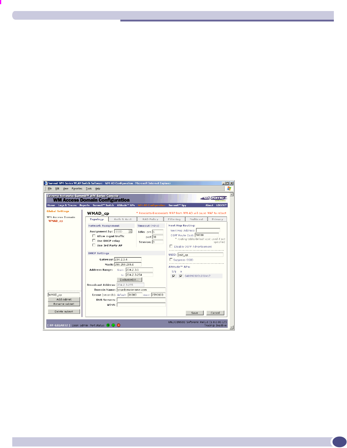
1In the entry field above the Add subnet button, key in a unique name for the new WM-AD.
2Click on Add subnet. The name appears in the list above.
3Highlight the subnet name. The Topology screen appears.
Topology for a WM-AD
1Select the network Assignment by drop-down list:
●SSID (authentication by Captive Portal, or none)
●AAA (authentication by 802.1x)
2In the SSID box, key in the SSID that wireless devices will use to access the Altitude AP.
3From the list of Altitude APs available, check the ones to be assigned to this WM-AD.
4In the Timeout area, key in the various time limits to inactivity in a session.

Configuring the Summit WM-Series WLAN Switch Software 1.0
FCS Review Draft II
Summit WM-Series Switches, Altitude 350, and Summit WM-Series WLAN Switch Software Quick Start Guide
26
5To allow Management traffic on this WM-AD, click the checkbox on. (See User Guide.)
6If this WM-AD is to be used for third-party access points, click Use 3rd Party AP checkbox on. The
screen changes to include fields for IP Address and MAC Address of the access point.
To bypass the Summit WM's DHCP server, click Use DHCP Relay checkbox on. If not using DHCP
Relay, fill in fields for DHCP on the Summit WM:
7In the Network Address field, key in the network IP address for the WM-AD. In the Mask box, key
in the subnet mask for the IP address.
8The Address Ranges fields populate automatically (based on the IP address) with the range of IP
addresses to be assigned to wireless devices. You can modify these, in the from or to box, or by
defining Exclusions in the Exclusions window.
9In the Default Lease box, key in the default time limit that an IP address would be assigned. In the
Max Lease box, key in the maximum time. (Default values are provided.)
10 Fill in: Domain Name, DNS Servers, WINS (if appropriate).
11 To save this WM-AD configuration, click on the Save button.
When the new Topology has been saved, the screen displays tabs for remaining configuration of the
WM-AD: Authentication & Accounting, RAD Policy, Multicast, Filtering and Privacy.
This guides provides an overview of the elements of a WM-AD only. For detailed instructions in setting
up a WM-AD, see the Summit WM-Series WLAN Switch Software 1.0 User Guide.
Network Assignment and Authentication for a WM-AD
If SSID was selected, there are two authentication options:
●None: The wireless device user will never be authenticated, but network access is still controlled by
the Non-Authenticated Filter.
●Captive Portal: The wireless device connects to the network, but can only access specified network
addresses defined in the Non-Authenticated Filter, including a webpage logon screen where the user
must input an ID and password for authentication (Captive Portal).
If AAA (802.1x) was selected, the wireless device user first logs onto the user's operating system. The
Summit WM sends the authentication request to a RADIUS server. If access is allowed, the Controller
assigns the device its IP address and allows network access controlled by filtering rules for the Filter ID
value associated with the user.
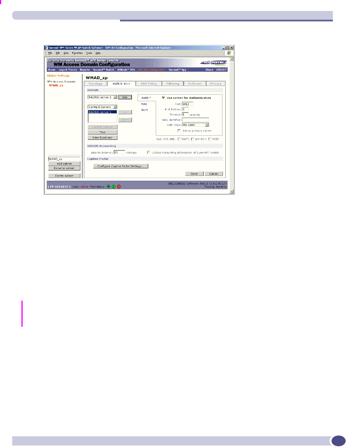
In the Authentication and Accounting screen, you select the RADIUS servers to be used for
Authentication, Accounting and MAC Authentication, as desired. Then define the parameters for each
type of authentication.
WM-Access Domain: Overview
FCS Review Draft II
Summit WM-Series Switches, Altitude 350, and Summit WM-Series WLAN Switch Software Quick Start Guide 27
1Click on the Authentication tab. The Captive Portal version of the screen is shown below.
2See the User Guide for details in assigning and configuring the servers for the three types of
authentication.
3For Captive Portal authentication, click on the Configure Captive Portal button to set up the Captive
Portal parameters.
4To save these settings, click on Save.
RADIUS Policy and Filtering for a WM-AD
In the RADIUS Policy screen, in the Filter ID Values box, key in the names of user groups that this WM-
AD will apply to. These names must match the Filter ID attribute names in the RADIUS server and will
appear in the drop-down list in the Filtering screen.
Four types of filters are applied by the Summit WM in the following order:
1Exception filter, to provide the administrator optional additional flexibility in securing the system
and blocking Denial of Service (DoS) attacks, on any type of WM-AD.
2Non-Authenticated filter, with filtering rules that apply before authentication, to control network
access and to direct users to a Captive Portal web page for login.
3Group filters (by Filter ID) for designated user groups, to control access to certain areas of the
network, with values that match the values defined for the RADIUS Filter ID attribute.
4Default filter, to control access if there is no matching Filter ID for a user.
Within each type of filter, define a sequence of filtering rules, in the order that you want them to take
effect. You define each rule to either allow or deny traffic, either “In” (from a wireless device in to the
network, or “Out” (from the network out to the wireless device).

Configuring the Summit WM-Series WLAN Switch Software 1.0
FCS Review Draft II
Summit WM-Series Switches, Altitude 350, and Summit WM-Series WLAN Switch Software Quick Start Guide
28
1Click on the Filtering tab.
2For assignment by SSID, select Non-Authenticated from Filter ID drop-down list.
For assignment by AAA 802.1x, select a named Filter ID.
3Define the filtering rules, and their order (see User Guide)
A “Deny All” rule is already in place. Use this as the final rule in the Non-Authenticated filter.
Privacy on a WM-AD
Privacy is a mechanism that protects data over wireless and wired networks, usually by encryption
techniques. Summit WM-Series WLAN Switch Software 1.0 supports:
●Wired Equivalent Privacy (WEP) which encrypts data sent between wireless nodes.
●Wi-Fi Protected Access (WPAv1 and WPAv2) privacy, in Enterprise Mode (which specifies 802.1x
authentication and requires an authentication server) or in Pre-Shared Key (PSK) mode (which relies
on a shared secret). Encryption is by Advanced Encryption Standard (AES) or by Temporal Key
Integrity Protocol (TKIP). If WPAv2 is selected, both WPAv1 and WPAv2 are supported
simultaneously, defaulting to the highest encryption method.
For further detailed information, see the Summit WM-Series WLAN Switch Software 1.0 User Guide.
Summit WM-Series WLAN Switch Software 1.0 Ongoing
Operations
When the WM Access Domain Services required have been defined, the initial configuration of the
Summit WM-Series WLAN Switch Software 1.0 system is complete. Ongoing operations include:
●Summit WM System Maintenance
●Altitude AP Maintenance
●Client Disassociate
●Logs and Traces
●Reports and Displays