Extreme Networks OAP36B HiPath Wireless Outdoor Access Point User Manual I
Extreme Networks, Inc. HiPath Wireless Outdoor Access Point I
UserManual.wiki
>
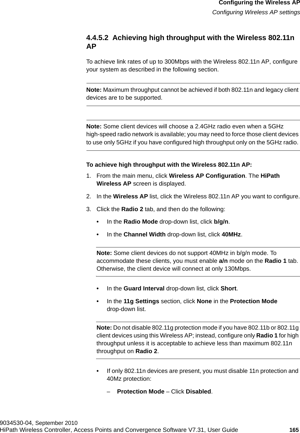
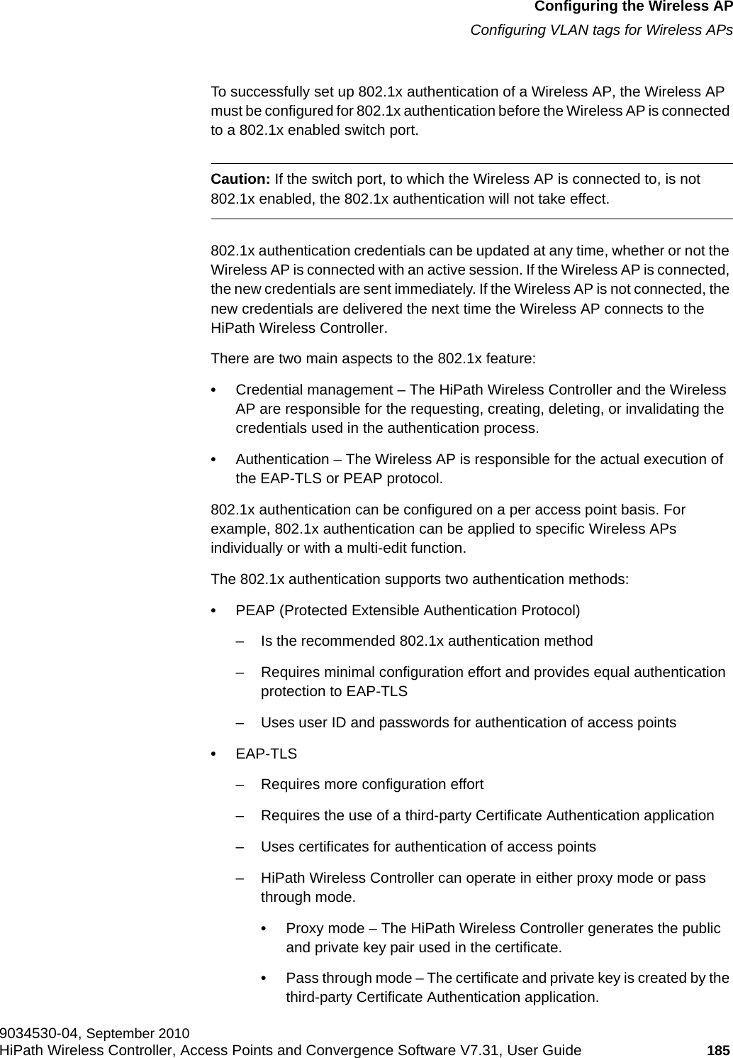
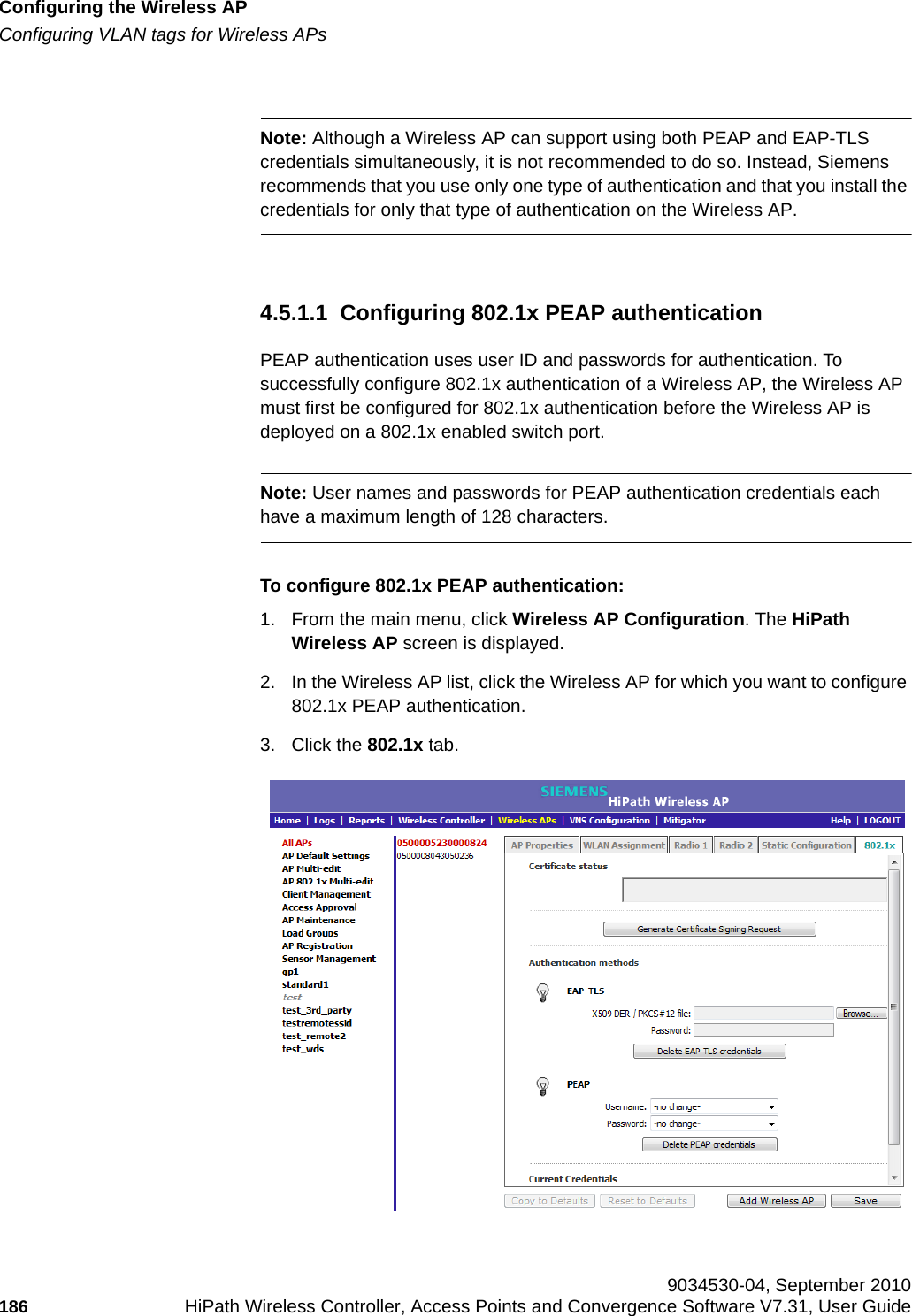
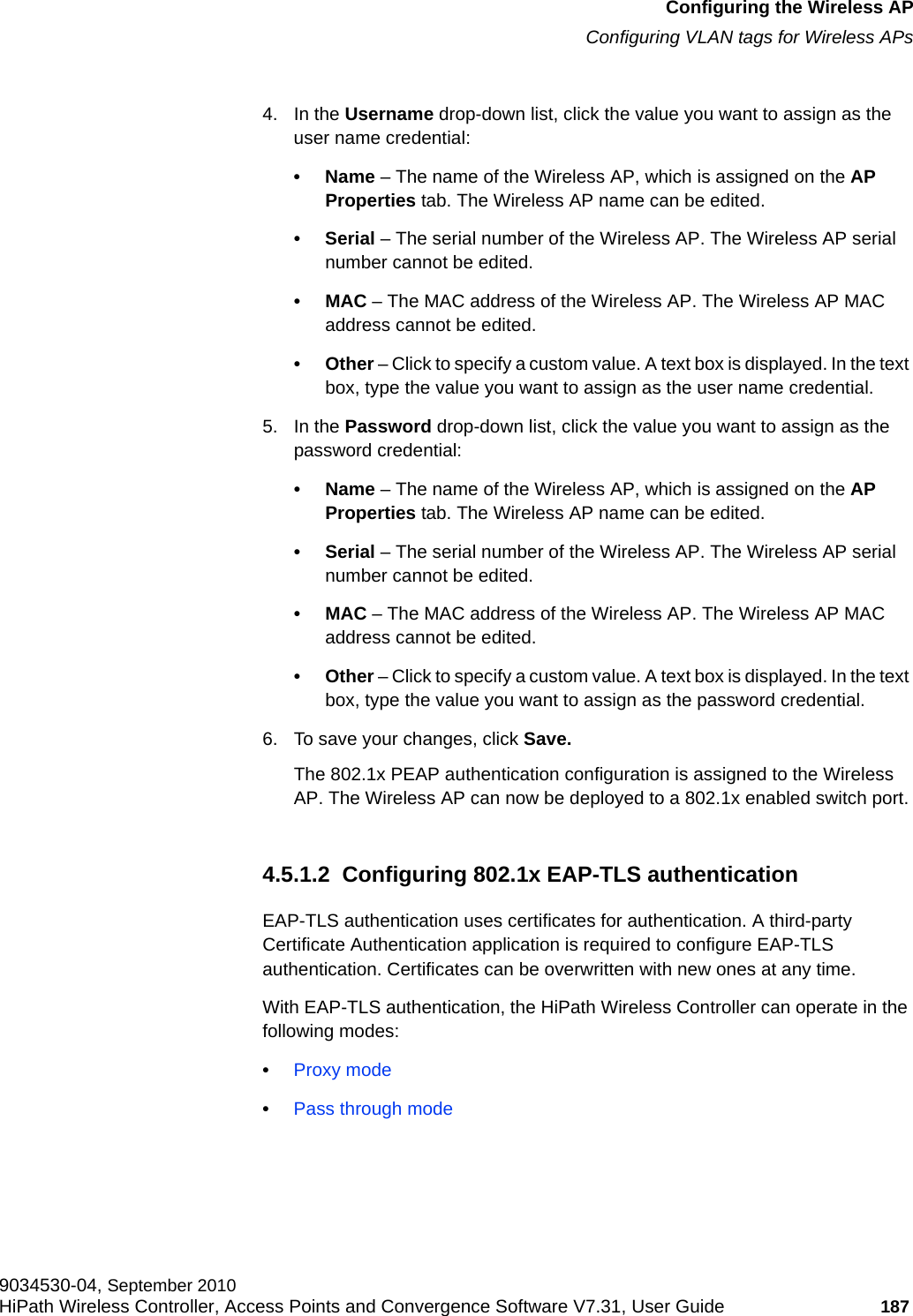
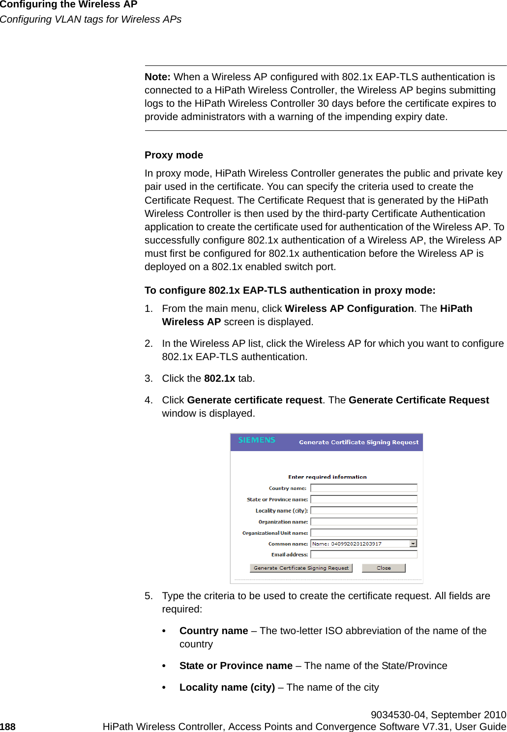
Extreme Networks
>
OAP36B User Manual
>
User Manual I
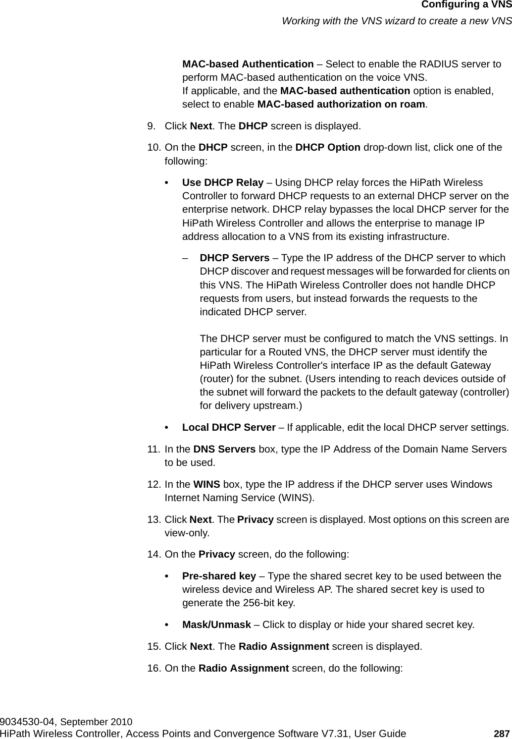
Contents
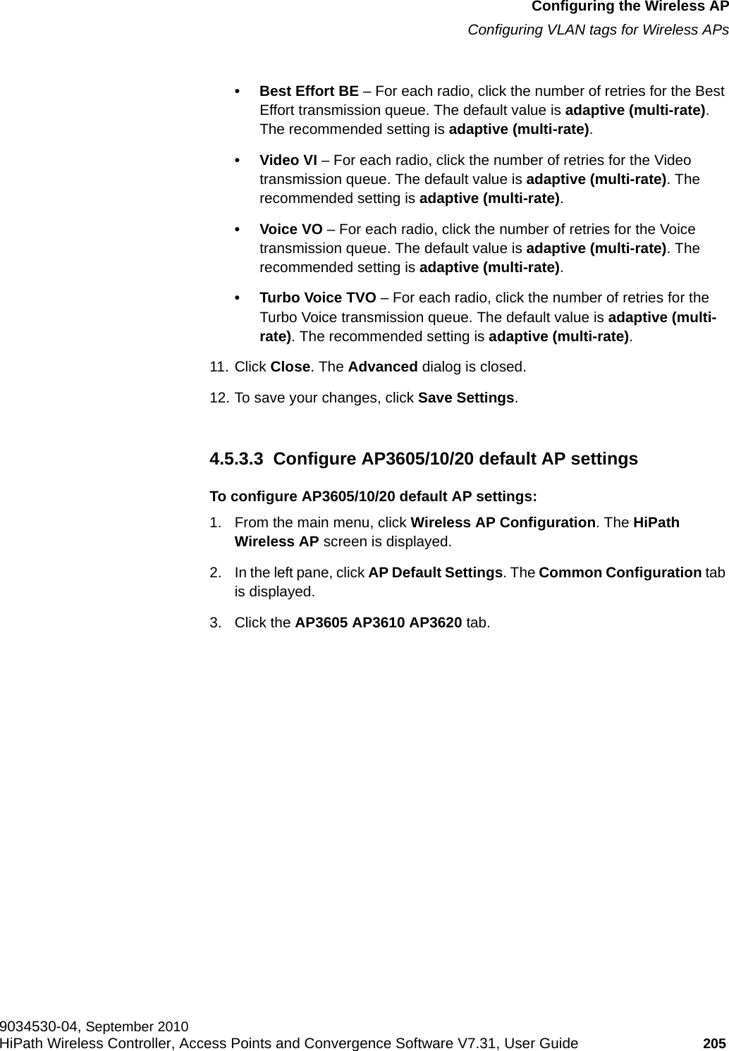
1.
User Manual I
2.
User Manual II
3.
User Manual
User Manual I
Navigation menu
Upload a User Manual
Namespaces
Wiki Guide
HTML
PDF
Info
Views
User Manual
Discussion / Help
Navigation


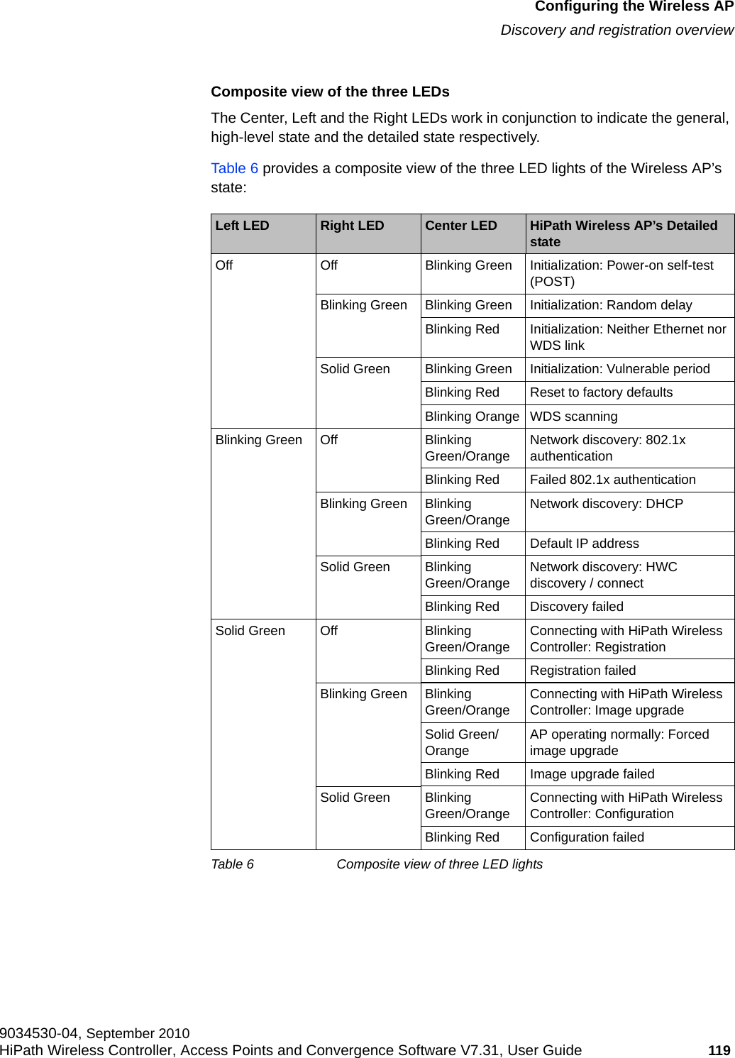
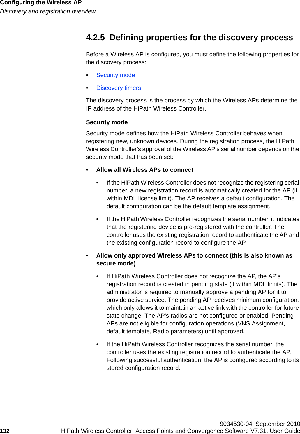
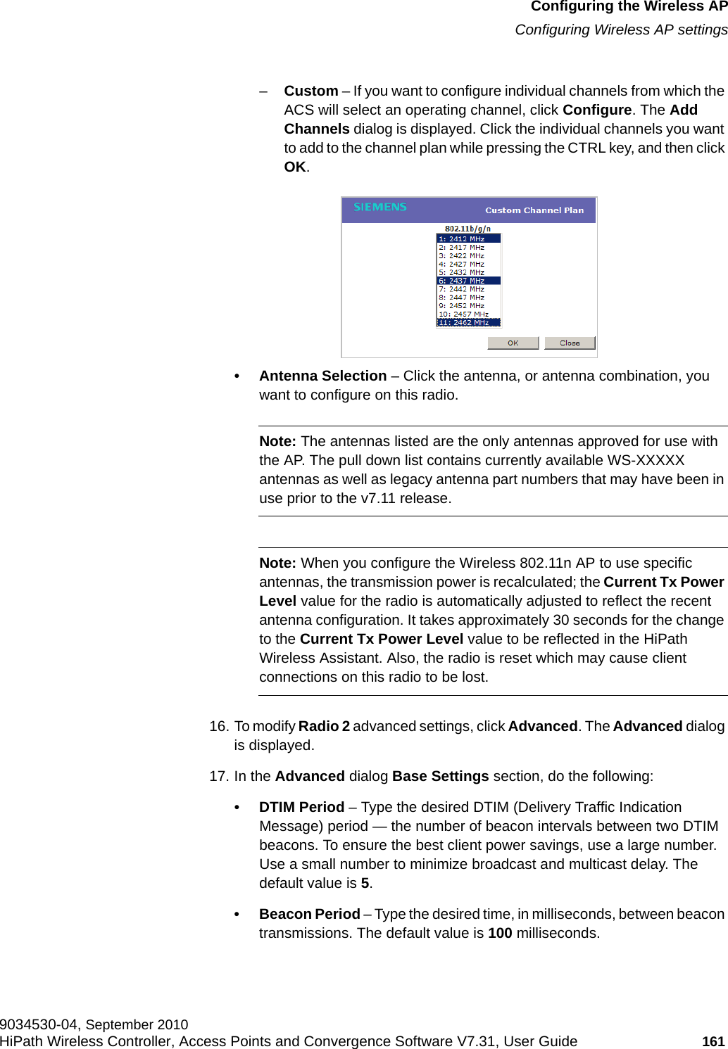
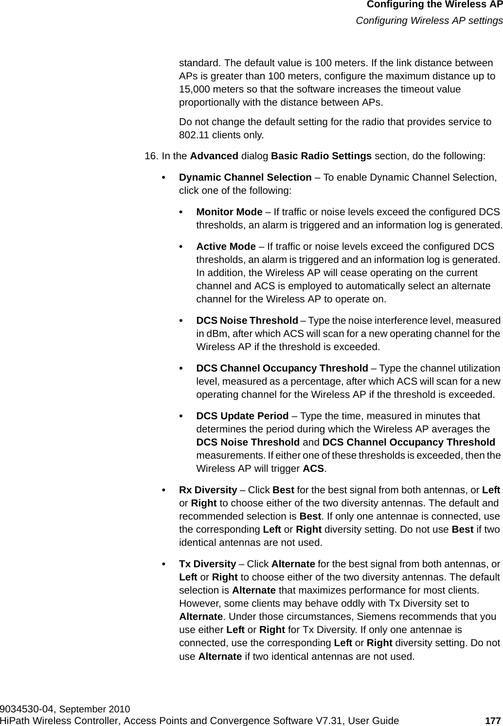
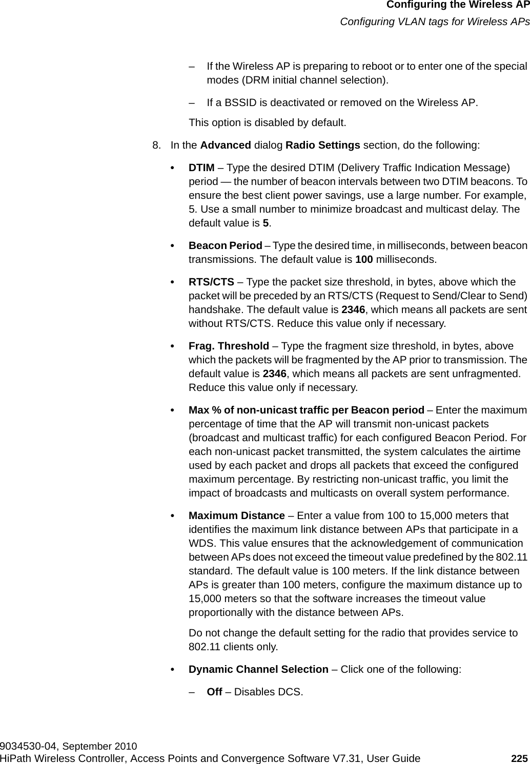
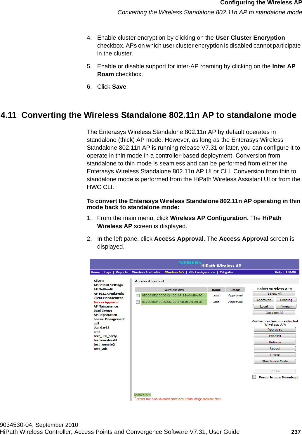
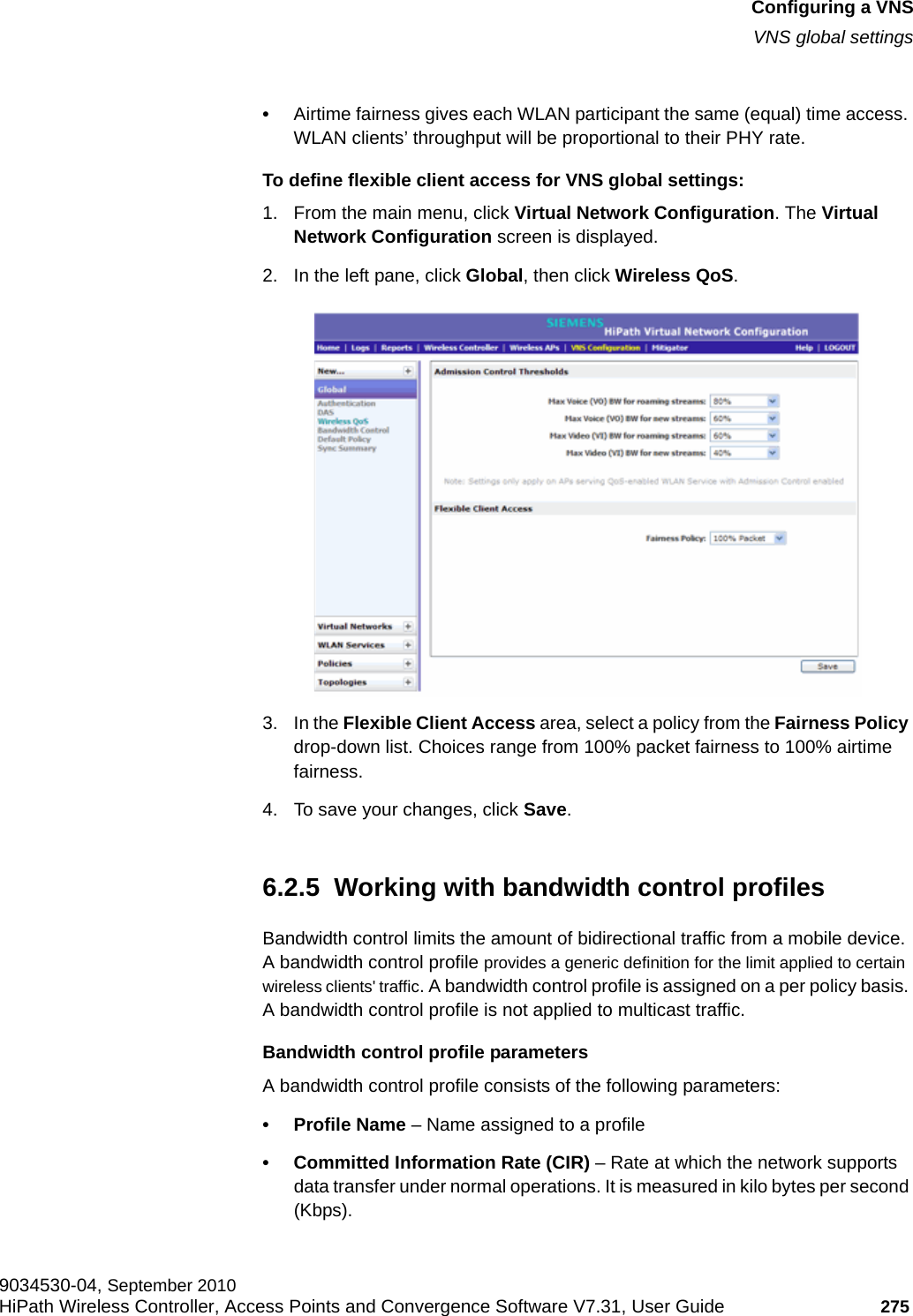
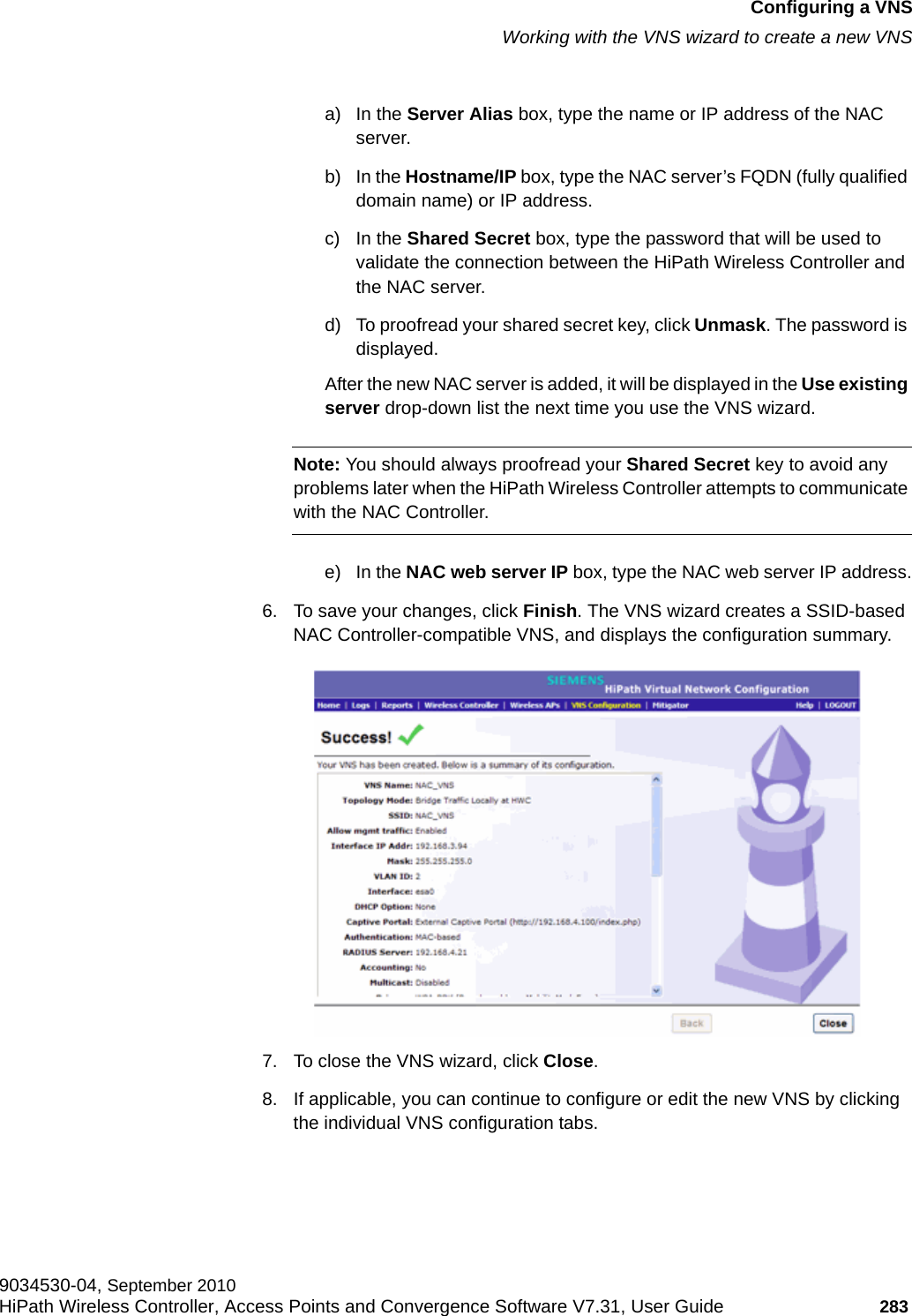
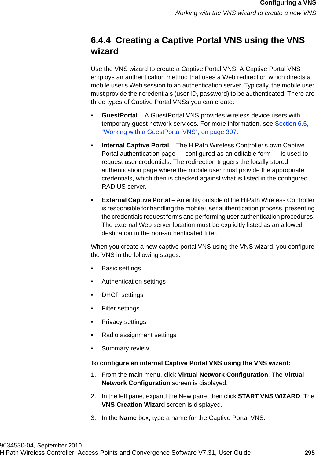
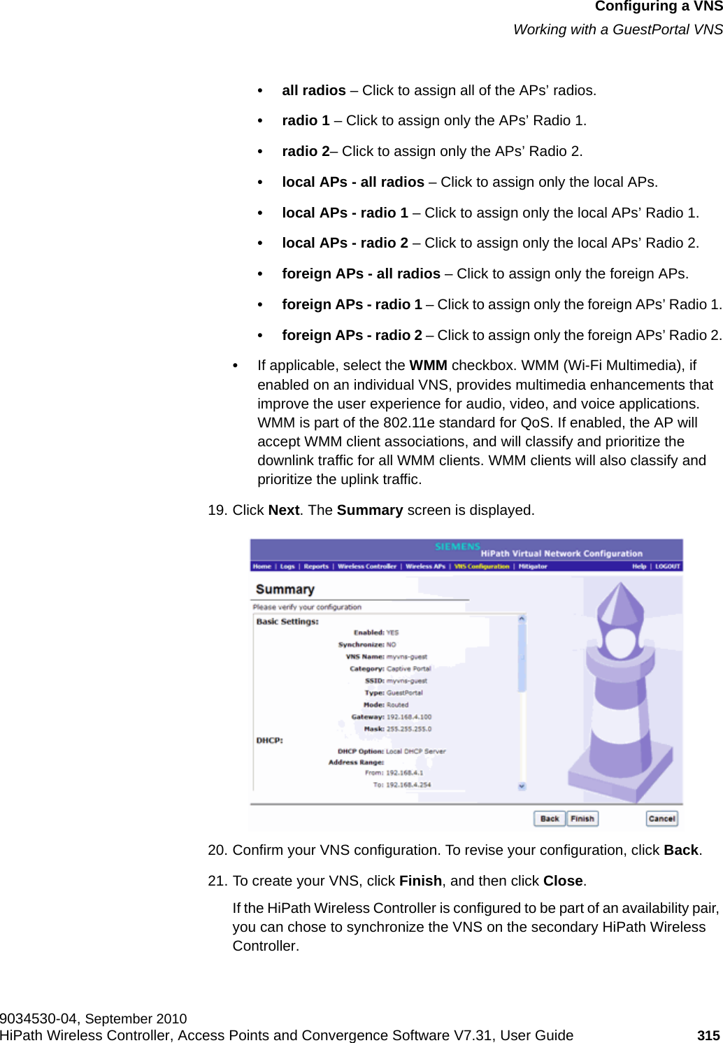
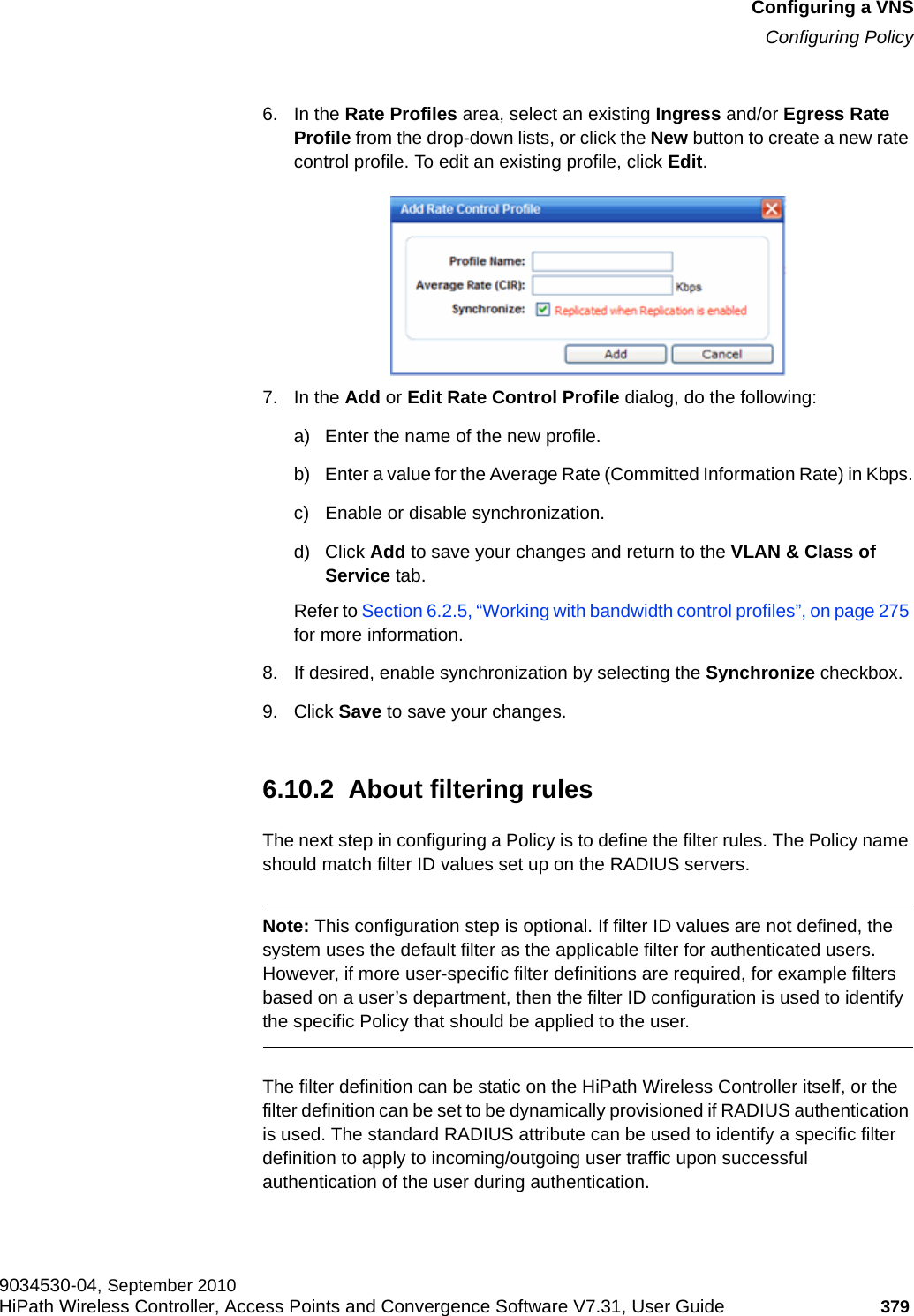
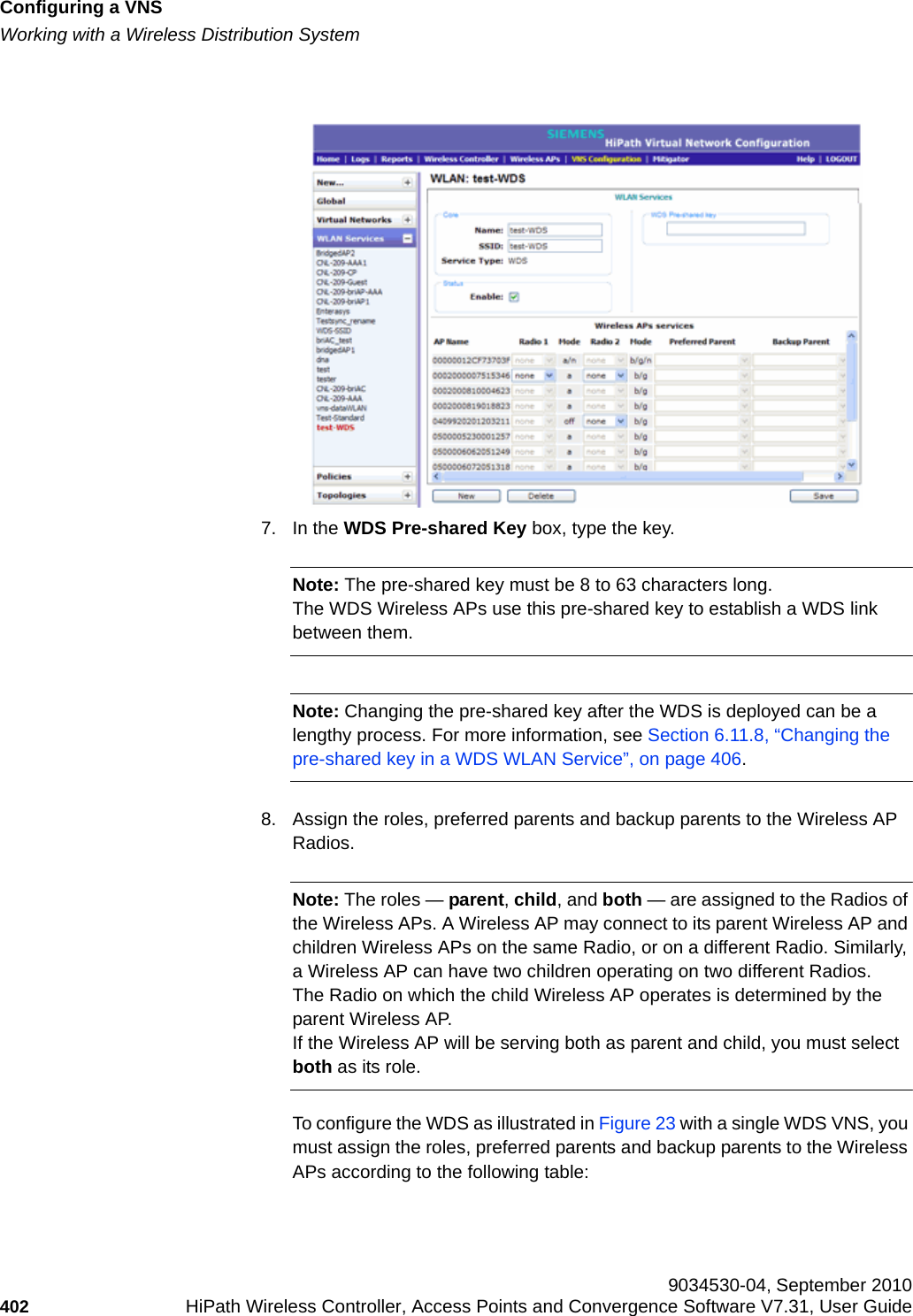
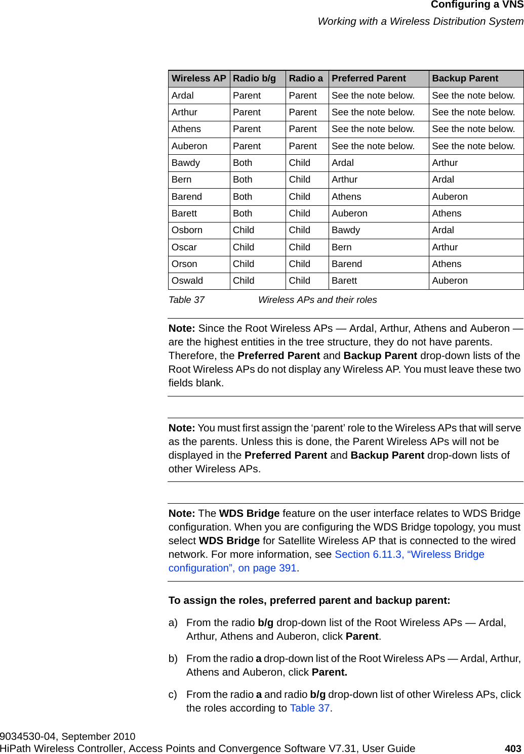
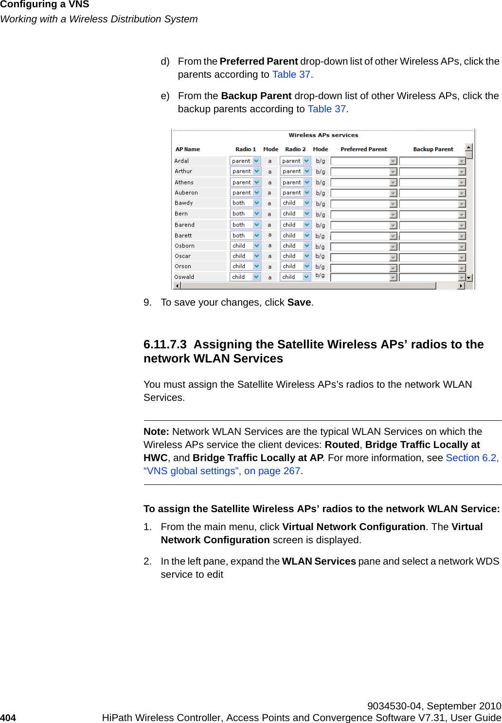
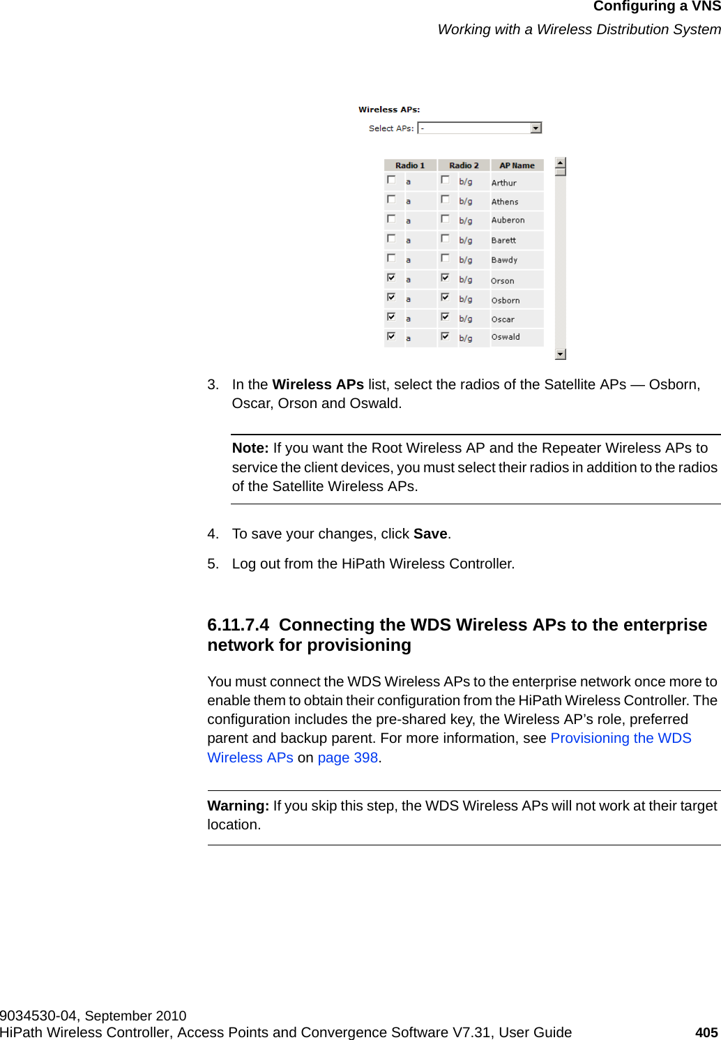
![hwc_pref.fmAbout this GuideFormatting conventions9034530-04, September 2010HiPath Wireless Controller, Access Points and Convergence Software V7.31, User Guide 13 1.3 Formatting conventionsThe HiPath Wireless Controller, Access Points and Convergence Software documentation uses the following formatting conventions to make it easier to find information and follow procedures:•Bold text is used to identify components of the management interface, such as menu items and section of pages, as well as the names of buttons and text boxes.For example: Click Logout.•Monospace font is used in code examples and to indicate text that you type.For example: Type https://<hwc-address>[:mgmt-port>]•The following notes are used to draw your attention to additional information:Note: Notes identify useful information, such as reminders, tips, or other ways to perform a task.Caution: Cautionary notes identify essential information, which if ignored can adversely affect the operation of your equipment or software.Warning: Warning notes identify essential information, which if ignored can lead to personal injury or harm.1.4 Additional documentationFor additional HiPath Wireless documentation, see the HiPath Wireless documentation athttp://www.enterasys.com/support/manuals](https://usermanual.wiki/Extreme-Networks/OAP36B.User-Manual-I/User-Guide-1395763-Page-13.png)

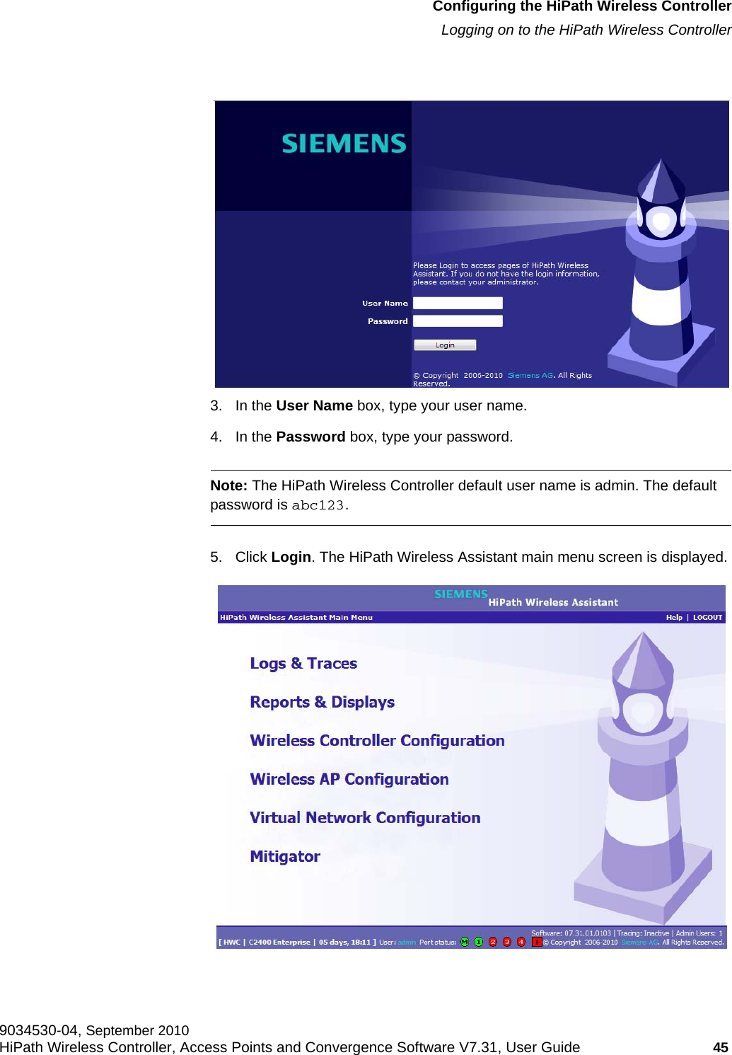
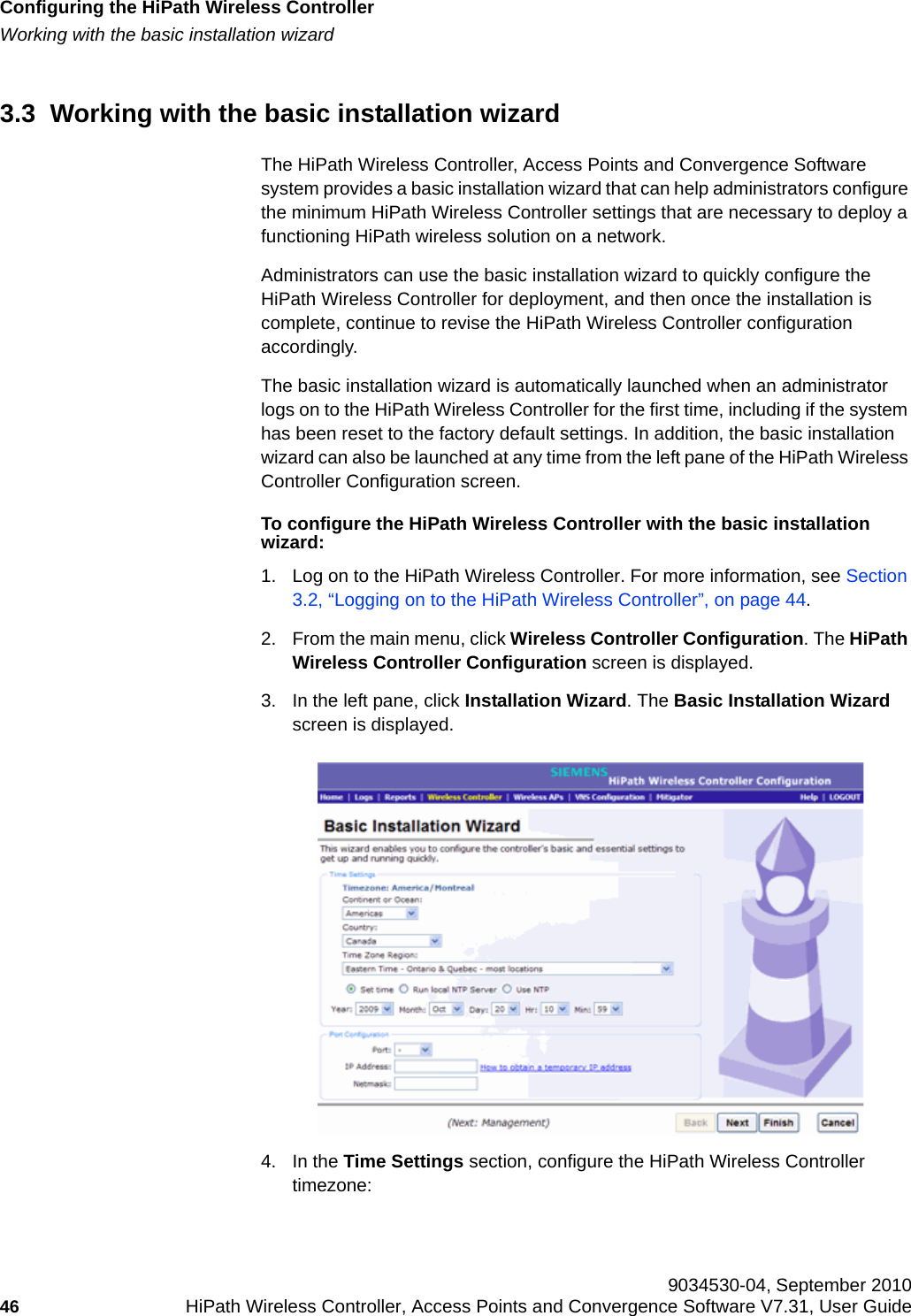
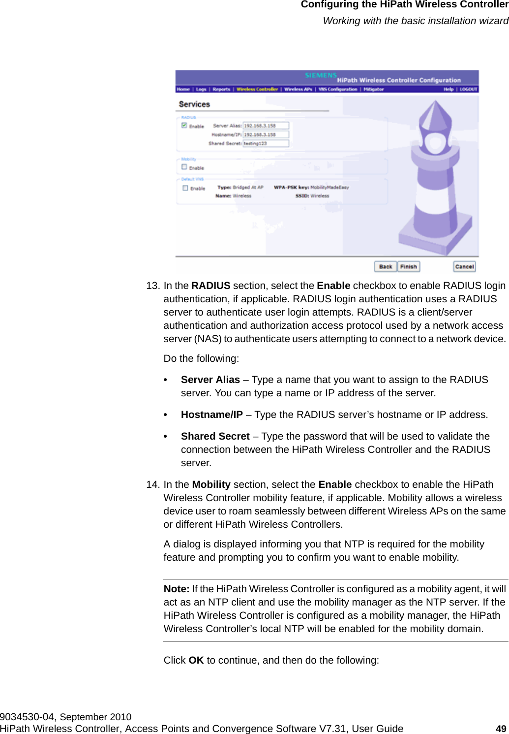
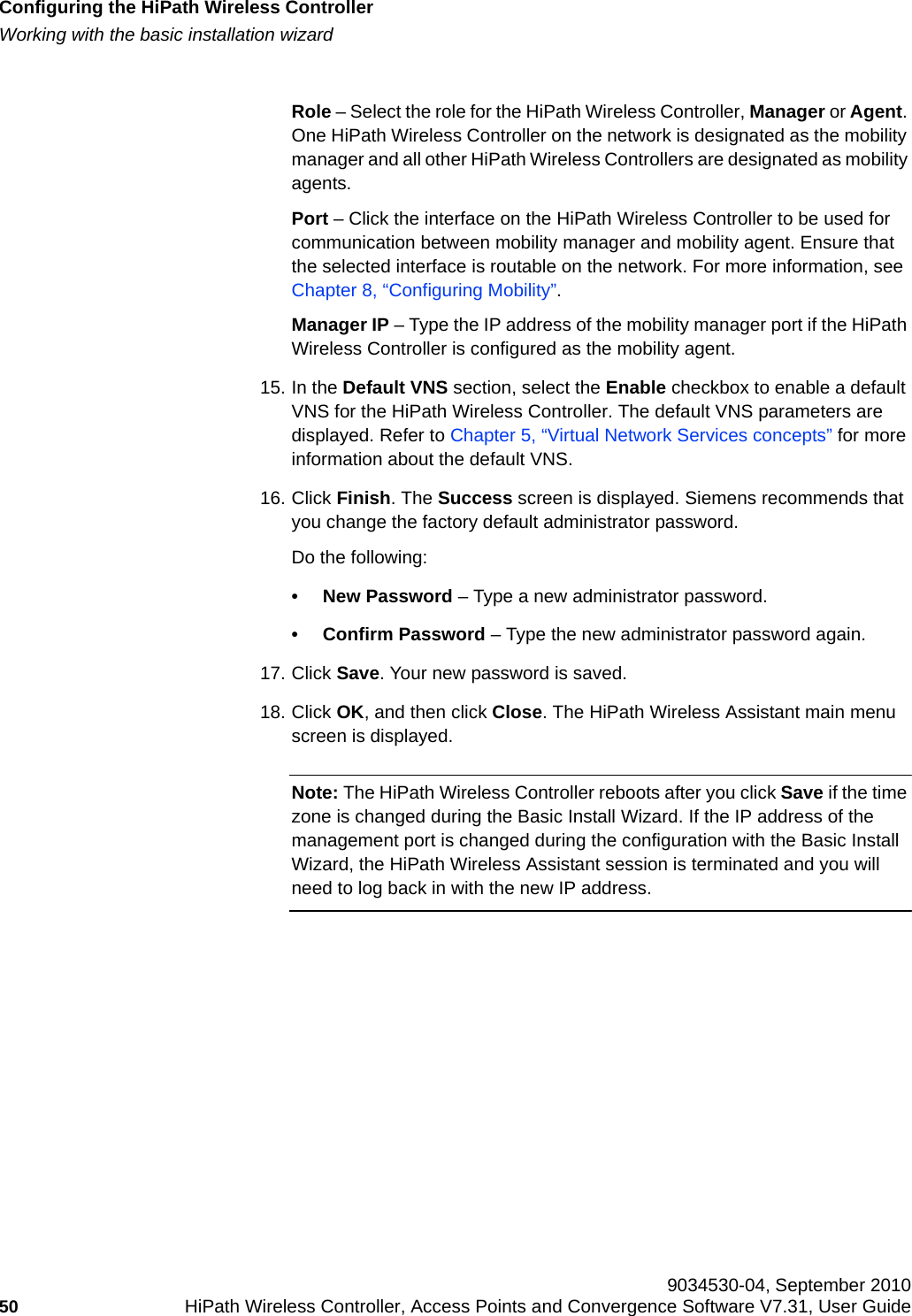
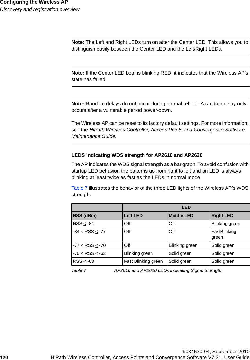
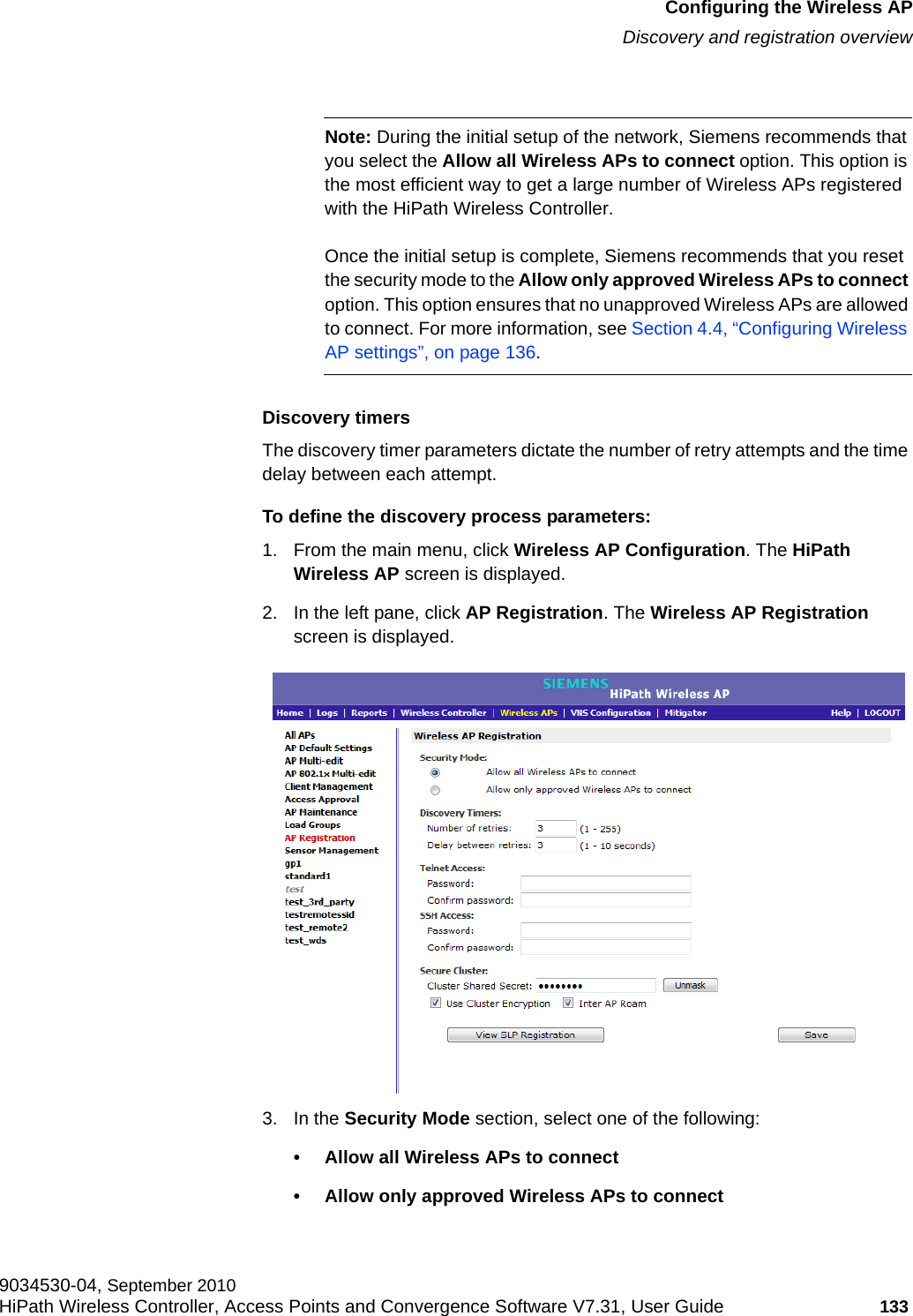
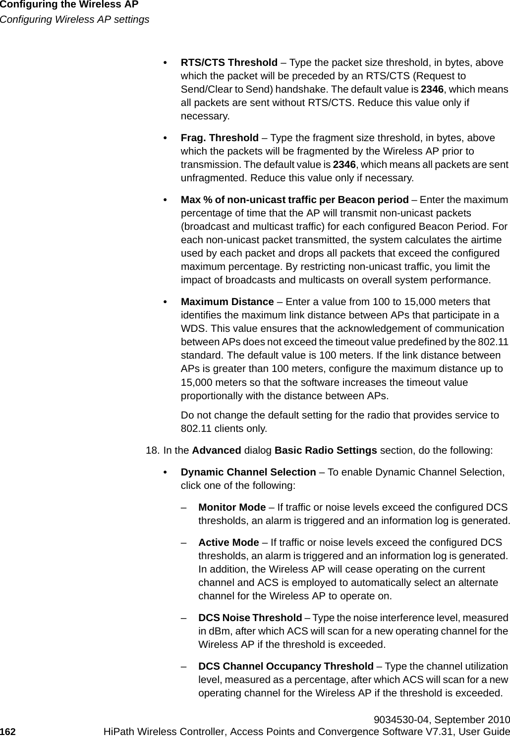
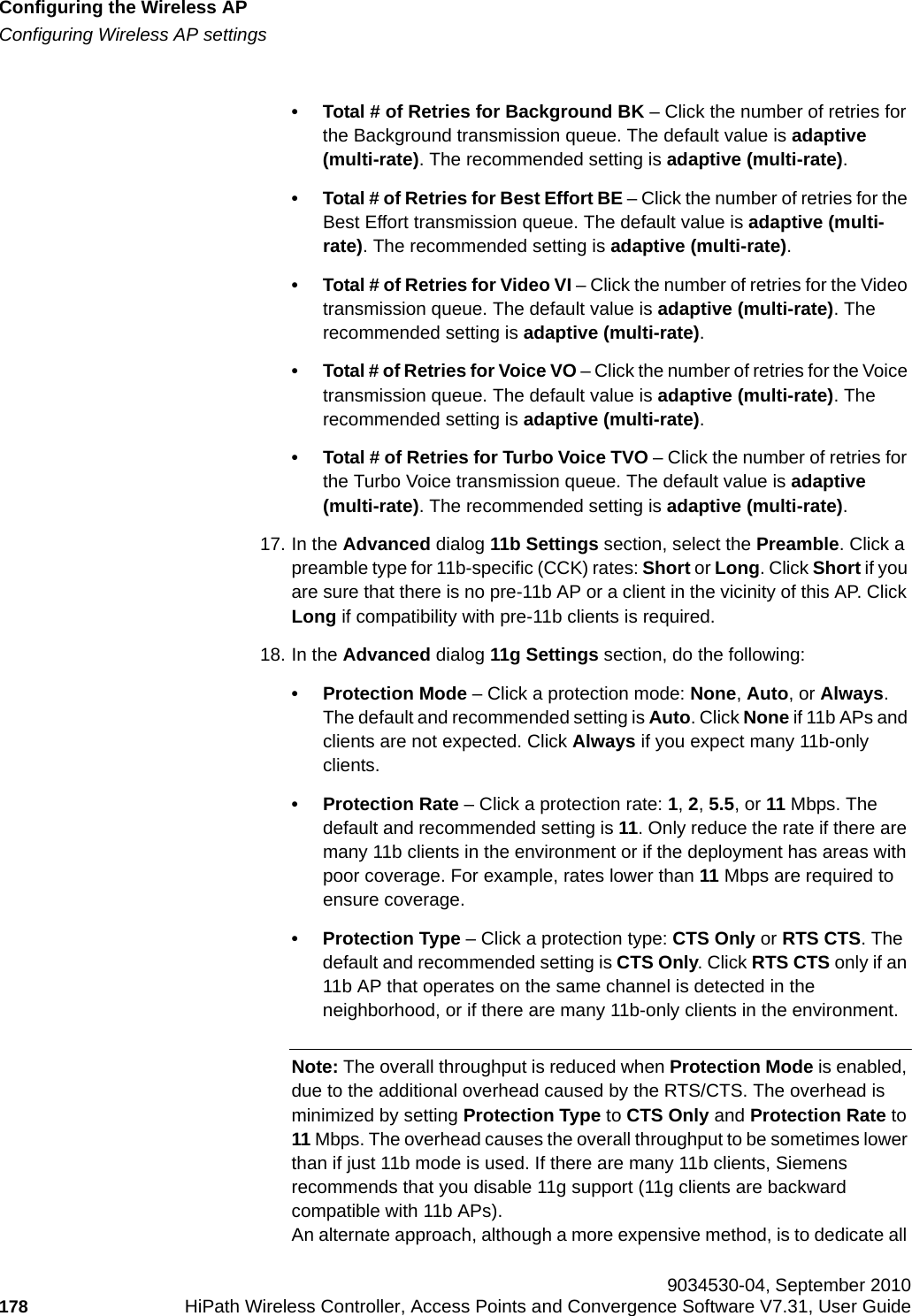
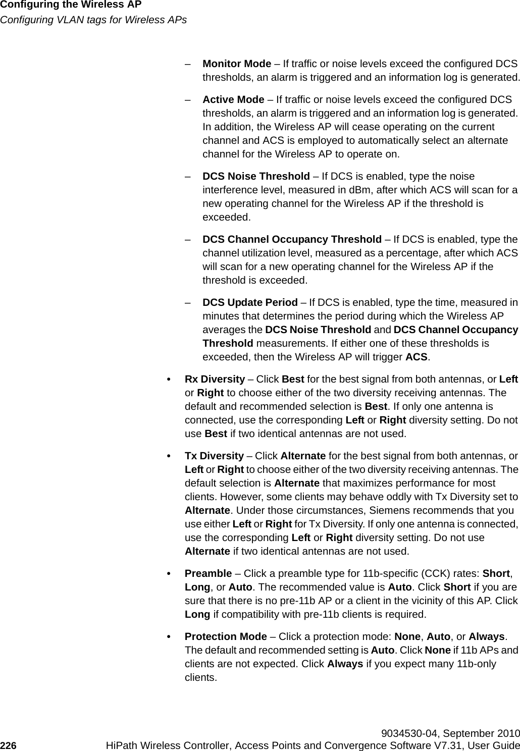
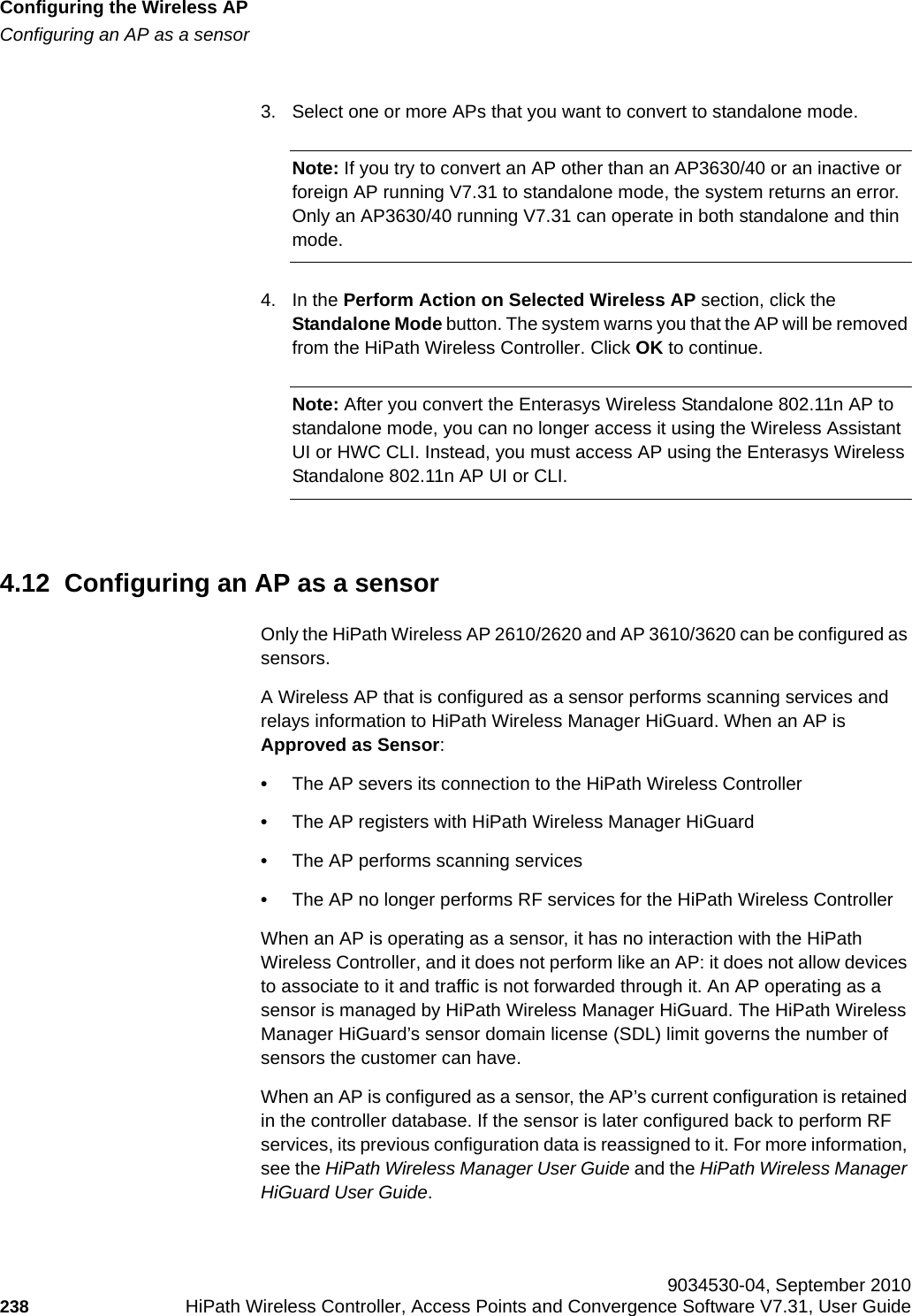
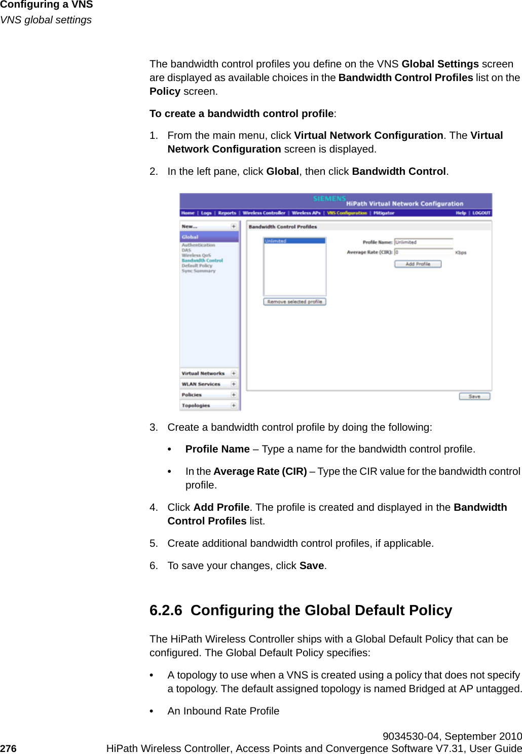
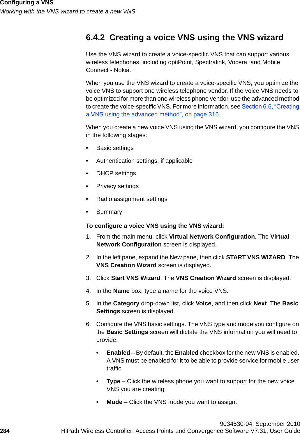
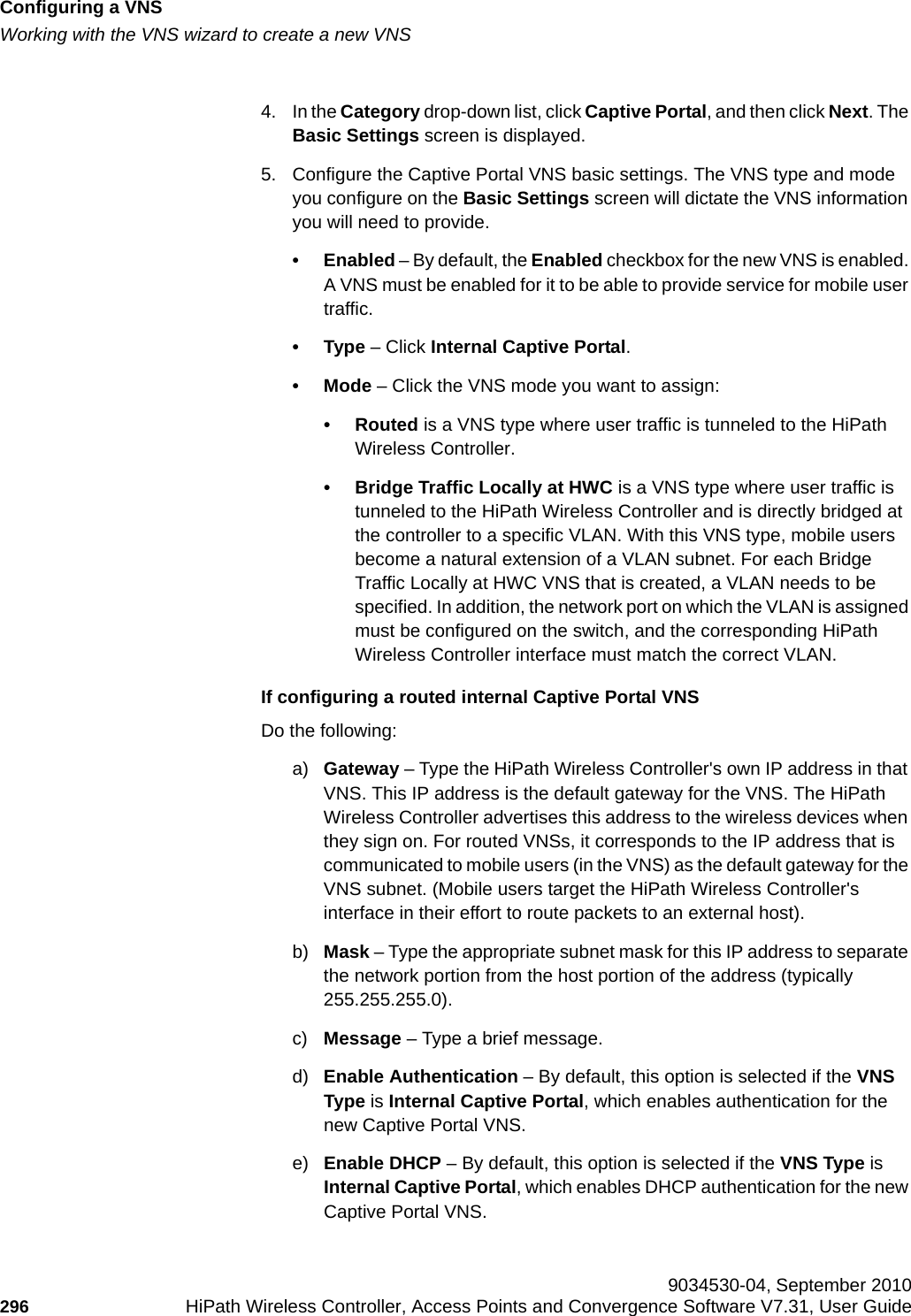
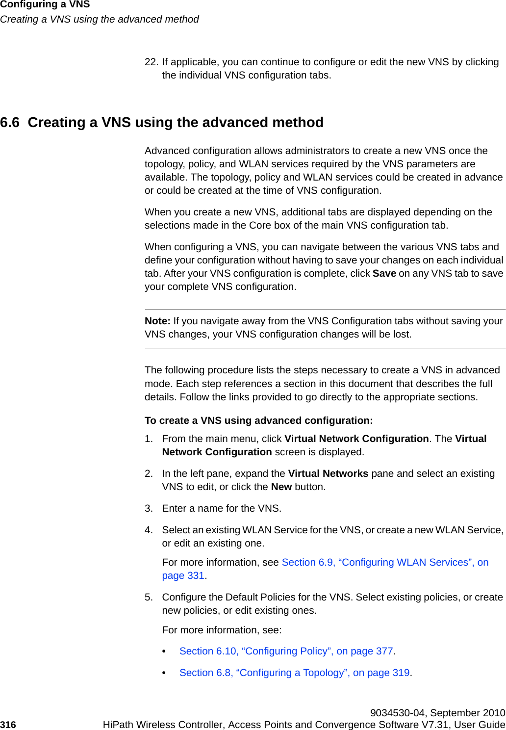
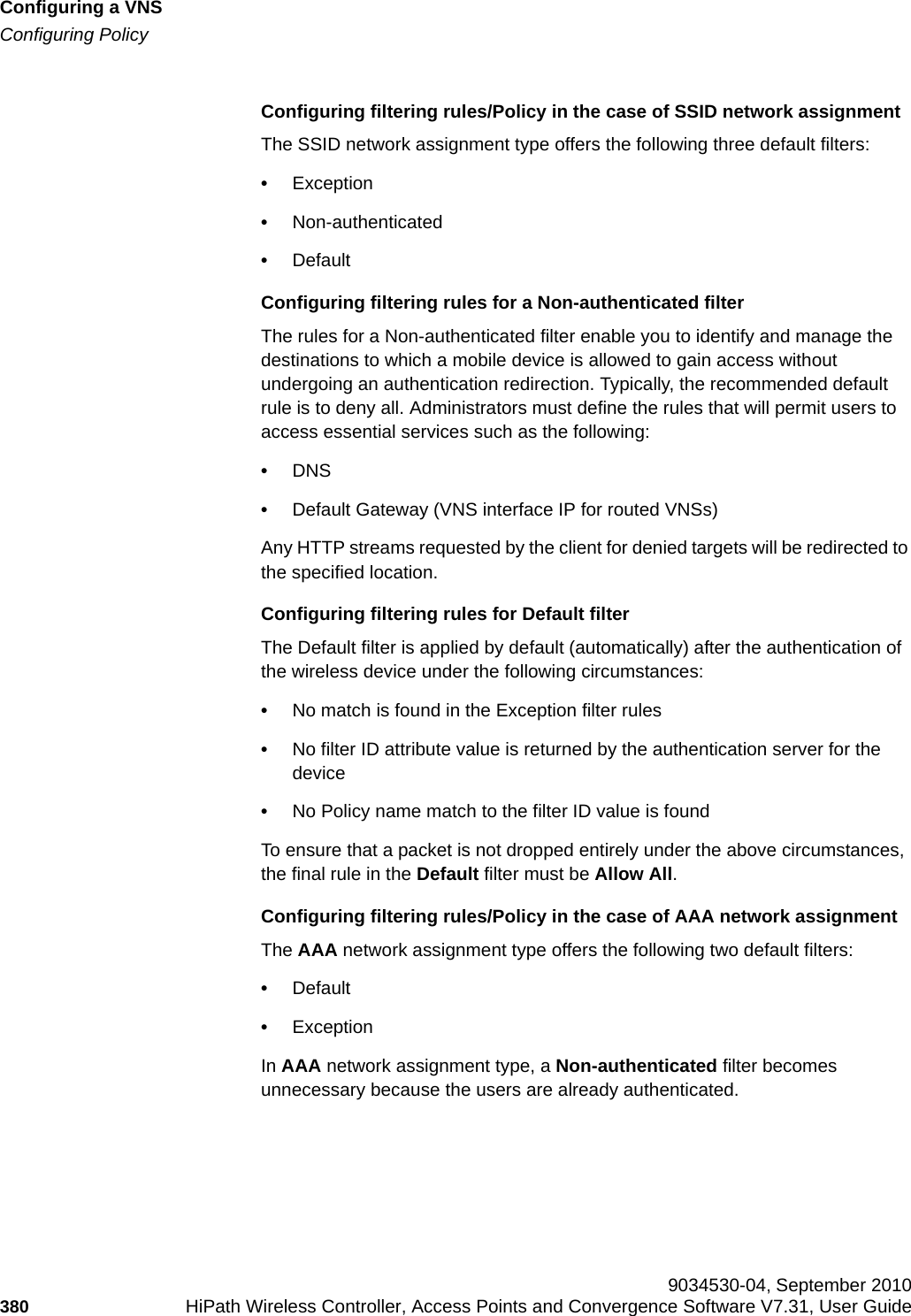
![hwc_startup.fmConfiguring the HiPath Wireless ControllerSystem configuration overview9034530-04, September 2010HiPath Wireless Controller, Access Points and Convergence Software V7.31, User Guide 43 For more information, see Section 3.4, “Configuring the HiPath Wireless Controller for the first time”, on page 51.5. Configure the traffic topologies your network must support. Topologies represent the Controller’s points of network attachment, therefore VLANs and port assignments need to be coordinated with the corresponding network switch ports. For more information, see Section 6.8, “Configuring a Topology”, on page 319.6. Configure policies. Policies are typically bound to topologies. Policy application assigns user traffic to the corresponding network point.– Policies define user access rights (filtering or ACL)– Polices reference user's rate control profile.For more information, see Section 6.10, “Configuring Policy”, on page 377.7. Configure WLAN services.– Define SSID and privacy settings for the wireless link.– Select the set of APs/Radios on which the service is present.– Configure the method of credential authentication for wireless users (None, Internal CP, External CP, GuestPortal, 802.1x[EAP]) For more information, see Section 6.9, “Configuring WLAN Services”, on page 331.8. Create the VNSs. A VNS binds a WLAN Service to a Policy that will be used for default assignment upon a users’ network attachment.You can create topologies, policies, and WLAN services first, before VNS configuration a VNS, or you can select one of the wizards (such as the VNS wizard), or you can simply select to create new VNS. The VNS page then allows for in-place creation and definition of any dependency it may require, such as:– Creating a new WLAN Service– Creating a new policy– Creating a new topology (within a policy)– Creating new rate controls, etc.The default shipping configuration does not ship any pre-configured WLAN Services, VNSs, or Policies.9. Install, register, and assign APs to the VNS.](https://usermanual.wiki/Extreme-Networks/OAP36B.User-Manual-I/User-Guide-1395763-Page-43.png)
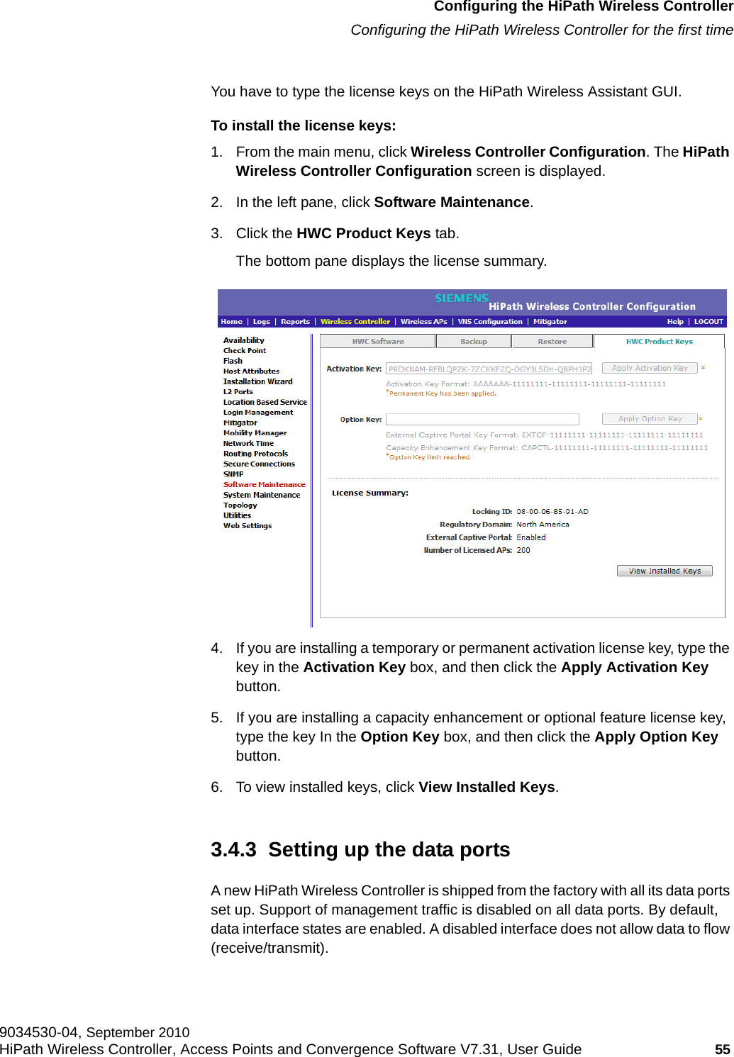
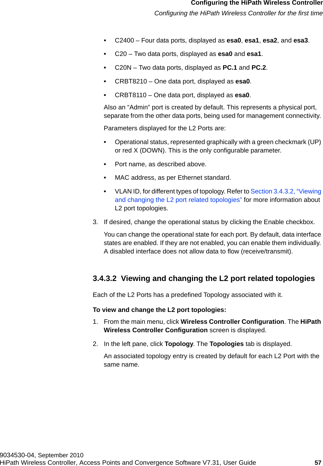
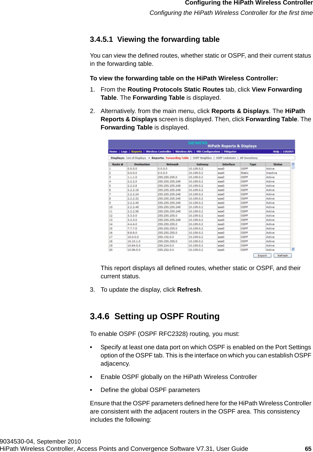
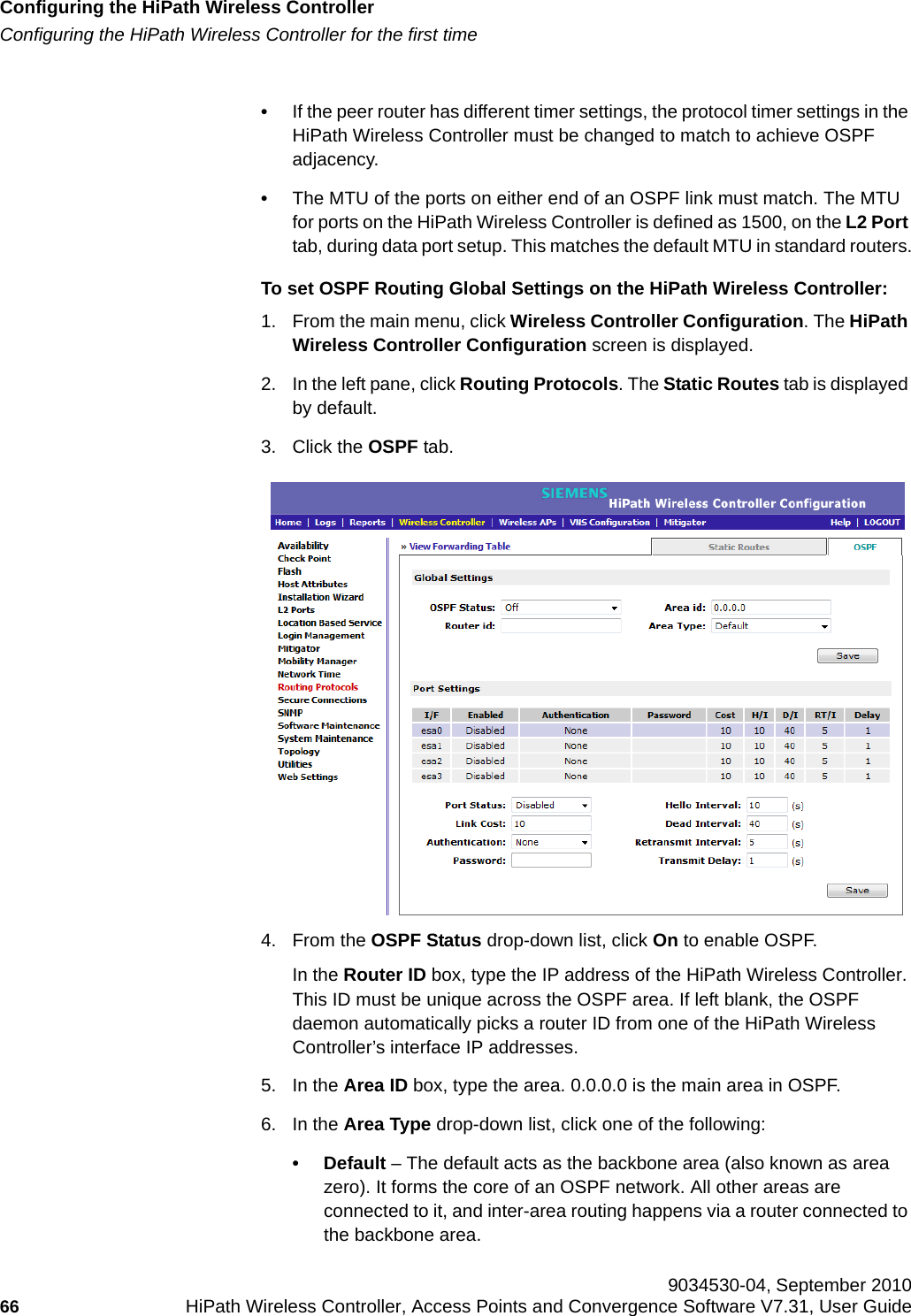
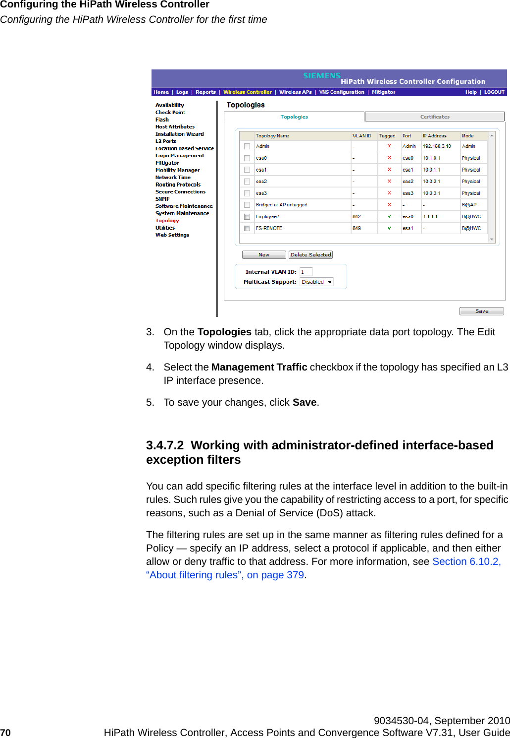
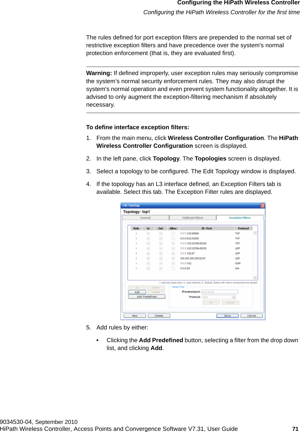
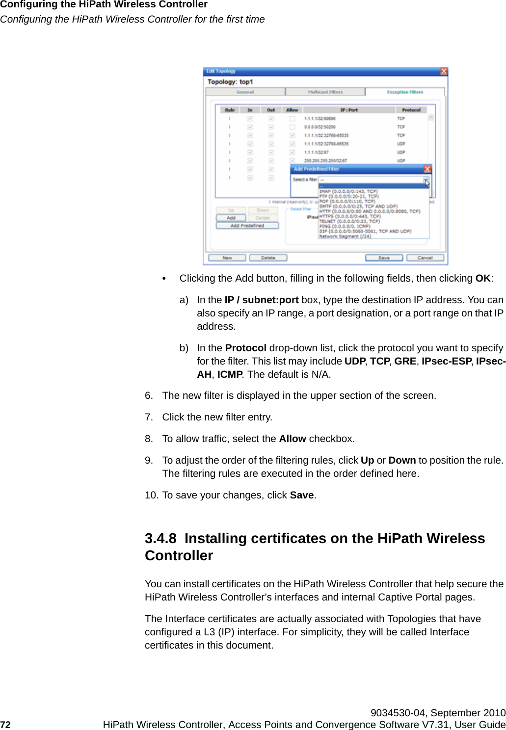
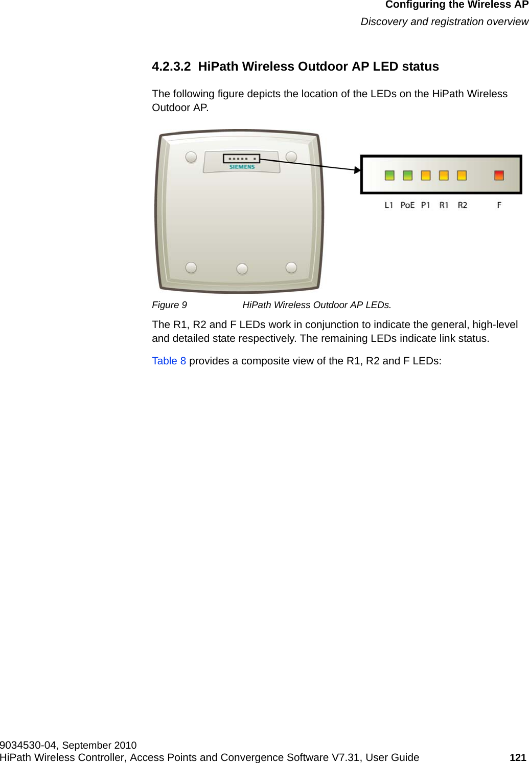
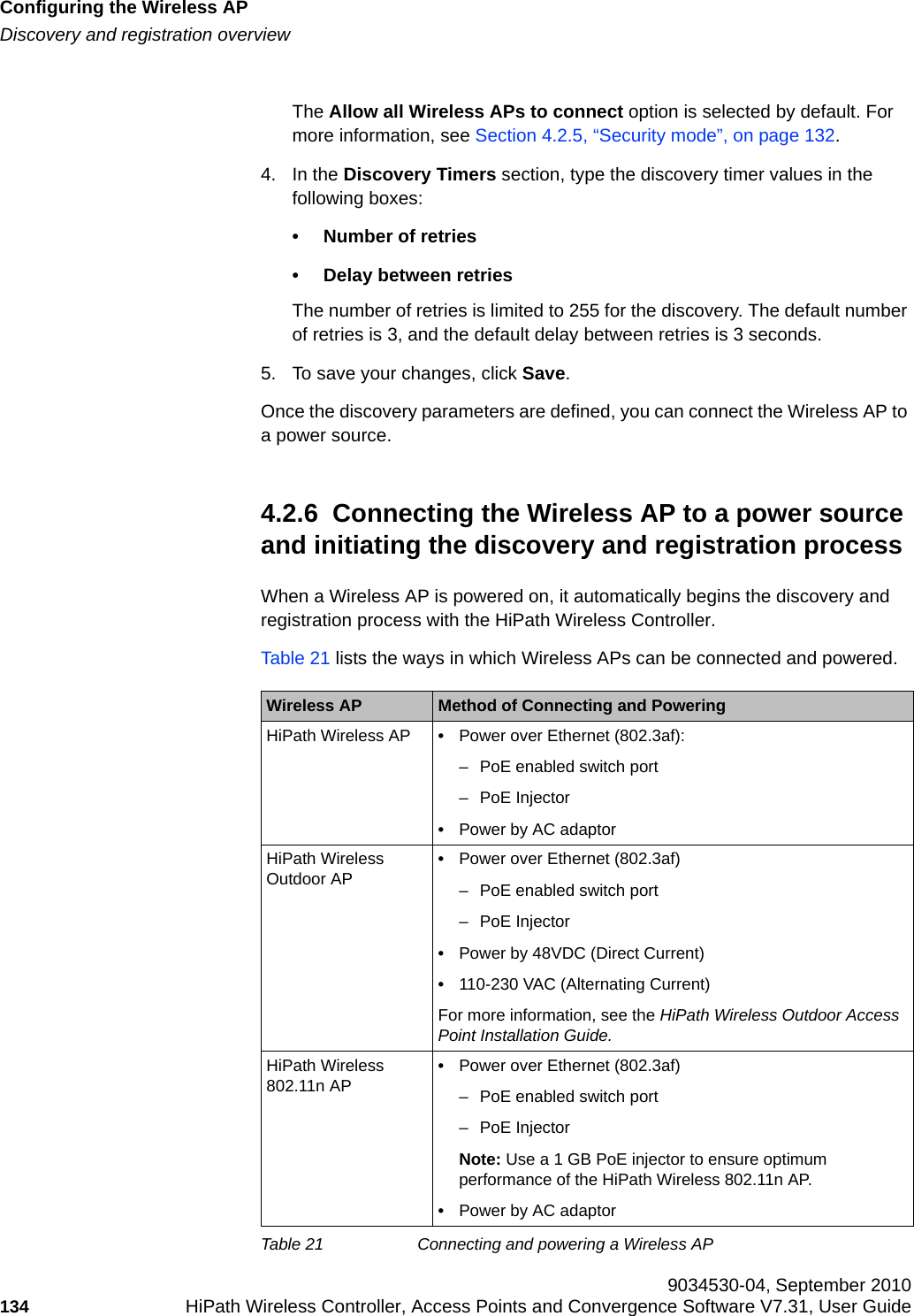
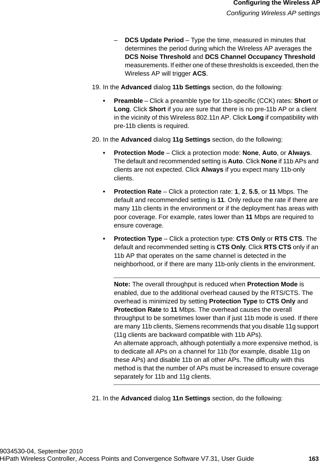
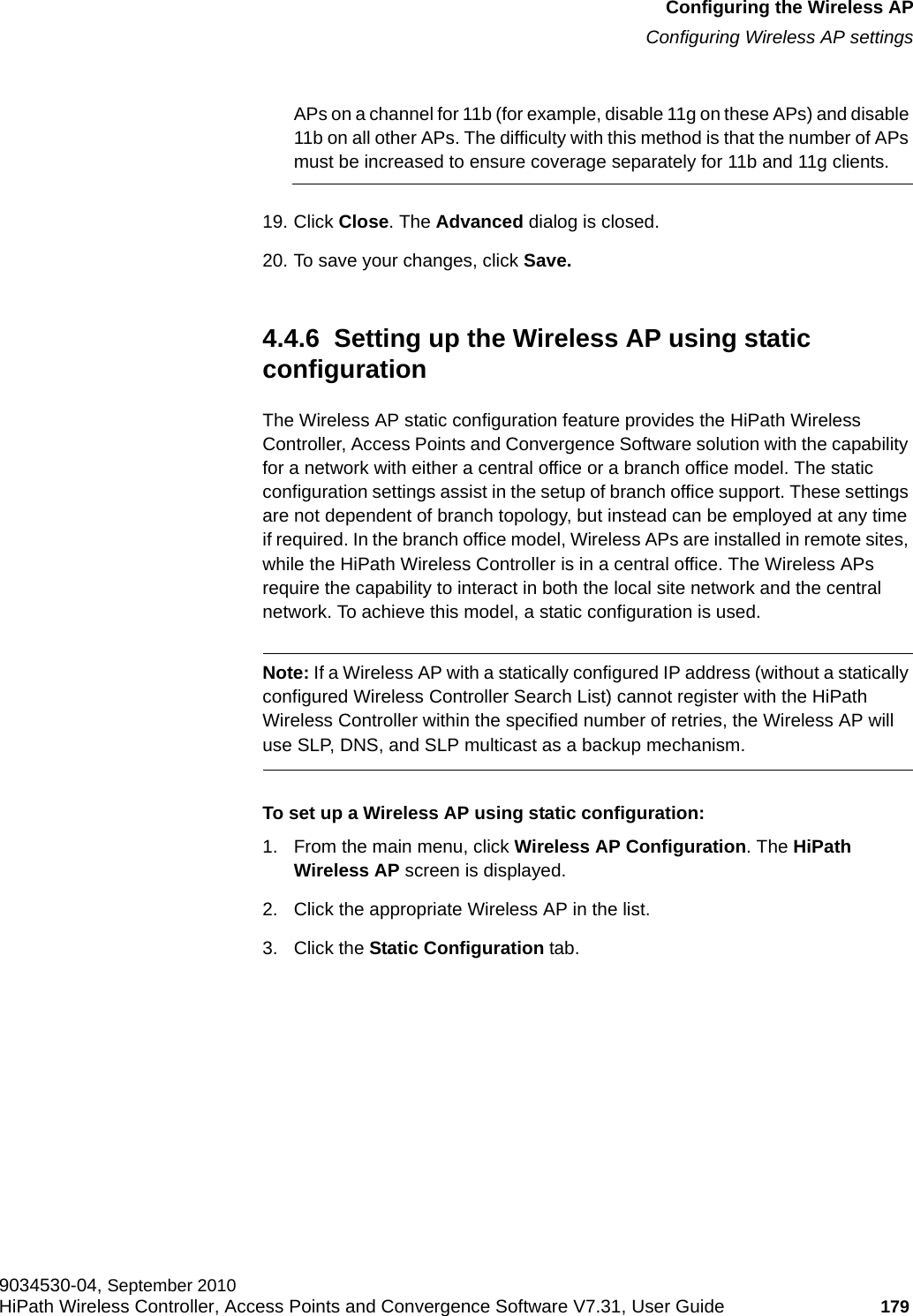
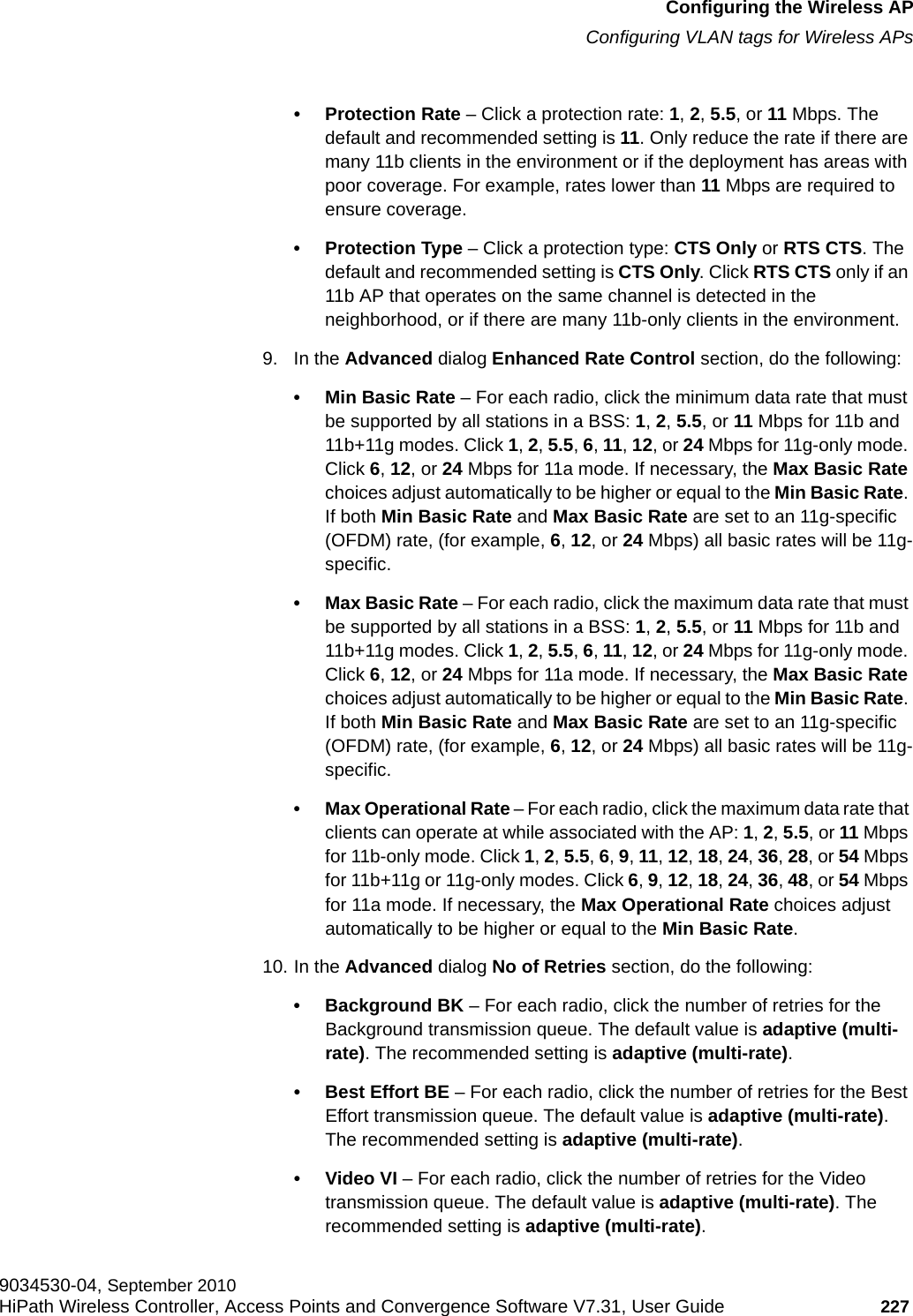
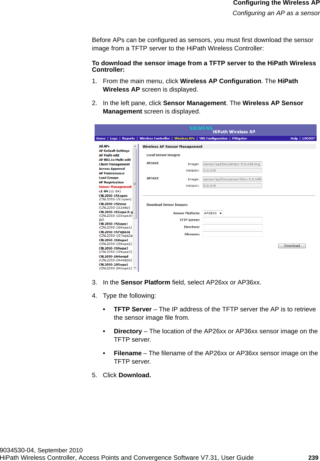
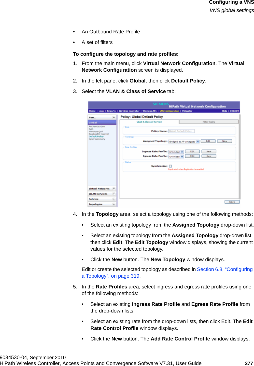
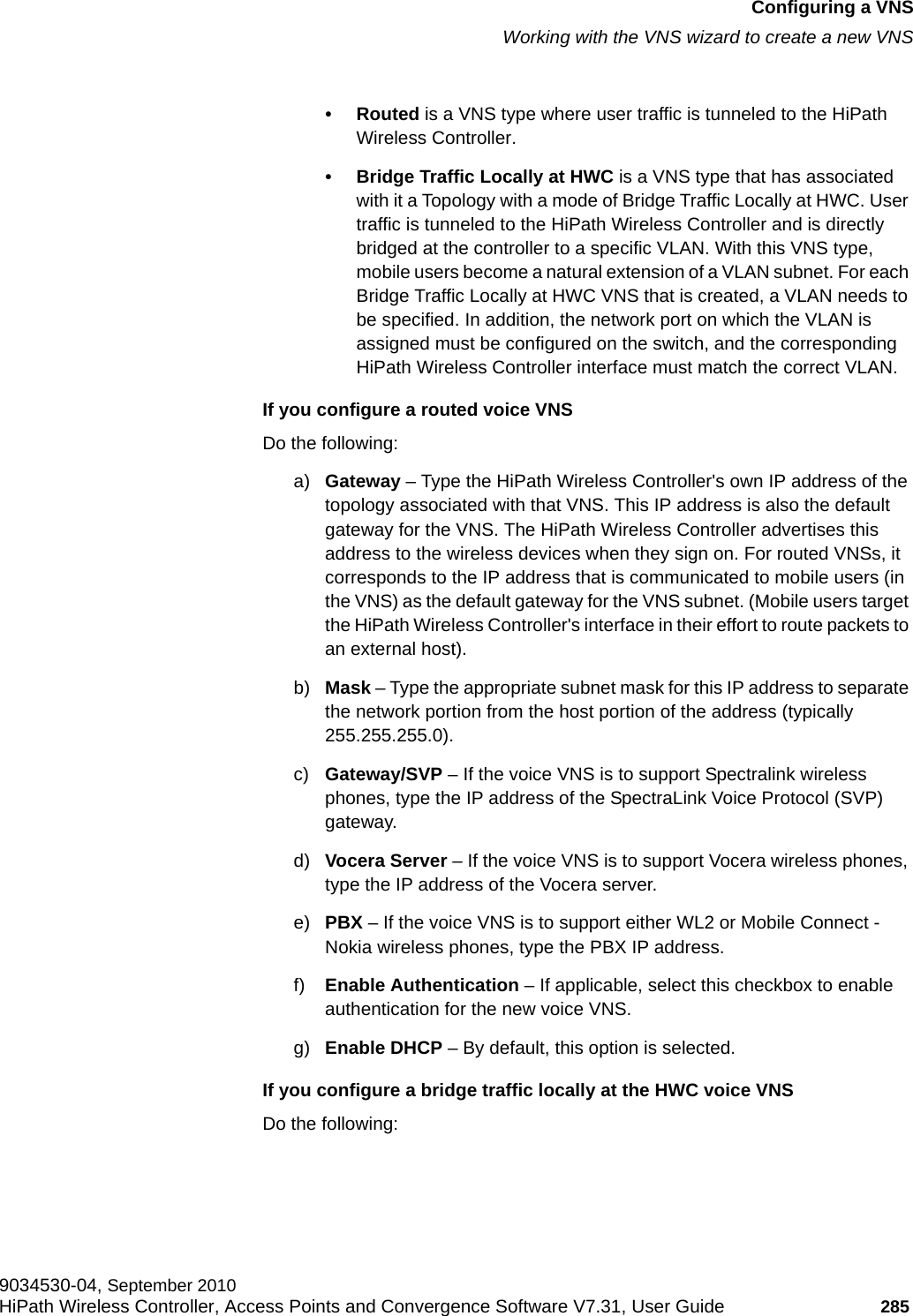
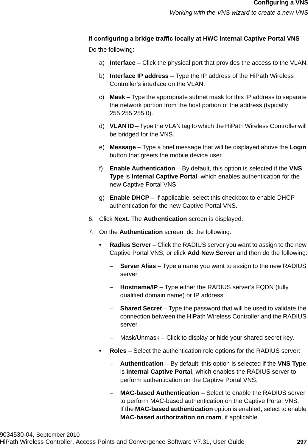
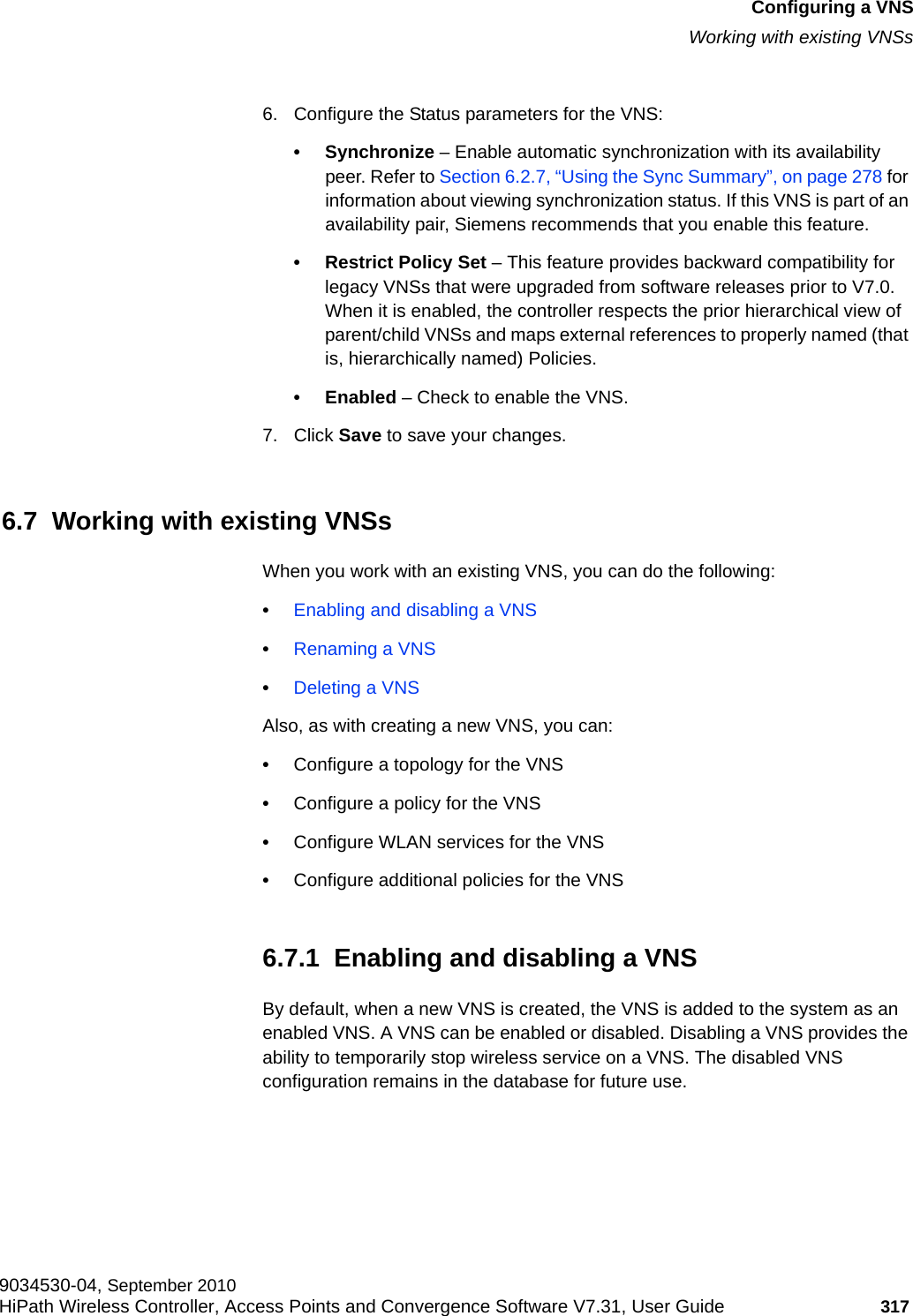
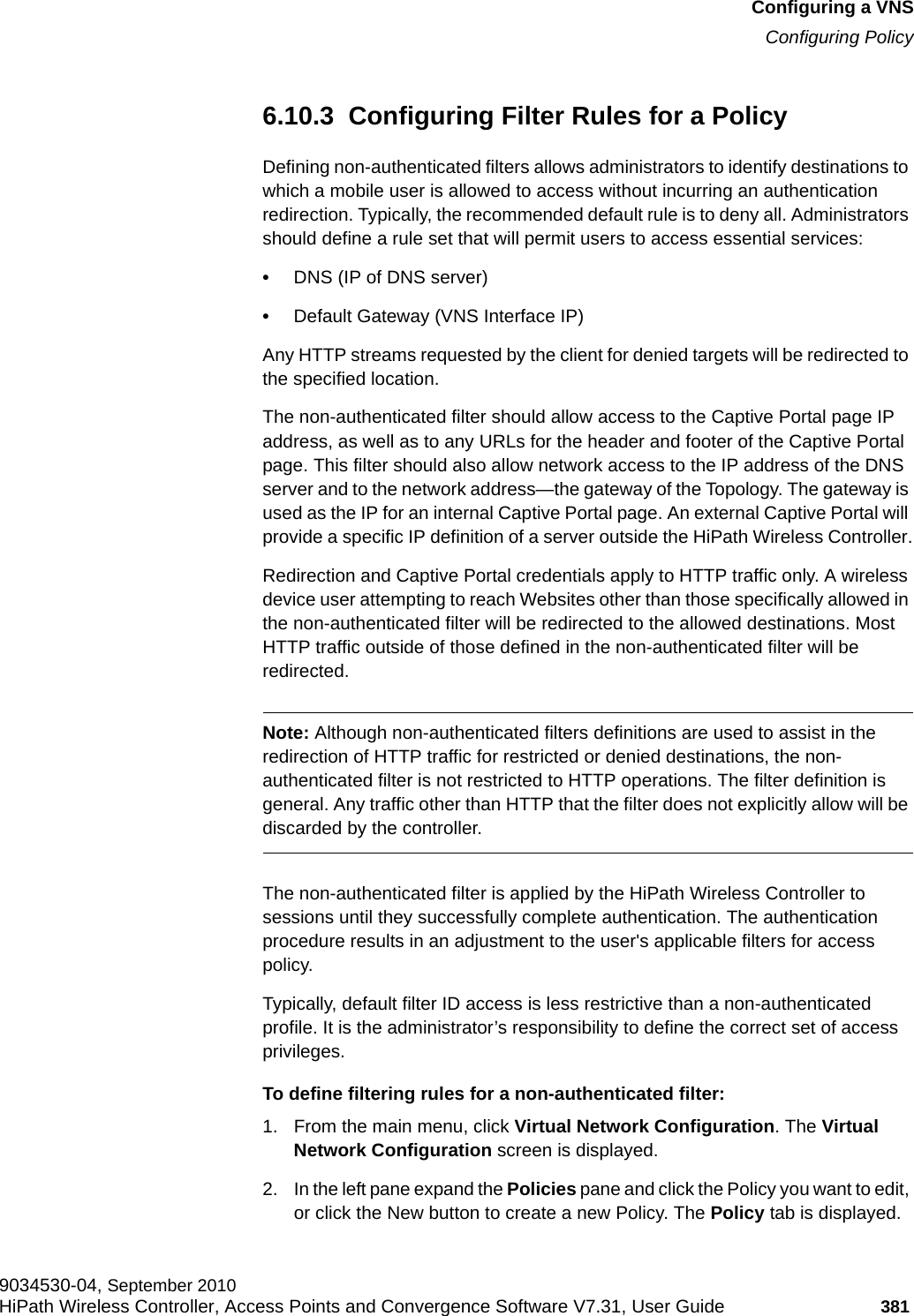
![hwc_startup.fmConfiguring the HiPath Wireless ControllerConfiguring the HiPath Wireless Controller for the first time9034530-04, September 2010HiPath Wireless Controller, Access Points and Convergence Software V7.31, User Guide 69 3.4.7.1 Built-in interface-based exception filtersOn the HiPath Wireless Controller, various interface-based exception filters are built in and invoked automatically. These filters protect the HiPath Wireless Controller from unauthorized access to system management functions and services via the interfaces. Access to system management functions is granted if the administrator selects the allow management traffic option in a specific topology.Allow management traffic is possible on the topologies that have L3 IP interface definitions. For example, if management traffic is allowed on a physical topology (esa0), only users connected through ESA0 will be able to get access to the system. Users connecting on any other topology, such as Routed or Bridged Locally at Controller, will no longer be able to target ESA0 to gain management access to the system. To allow access for users connected on such a topology, the given topology configuration itself must have allow management traffic enabled and users will only be able to target the topology interface specifically.On the HiPath Wireless Controller’s L3 interfaces (associated with either physical, Routed, or Bridged Locally at Controller topologies), the built-in exception filter prohibits invoking SSH, HTTPS, or SNMP. However, such traffic is allowed, by default, on the management port.If management traffic is explicitly enabled for any interface, access is implicitly extended to that interface through any of the other interfaces (VNS). Only traffic specifically allowed by the interface’s exception filter is allowed to reach the HiPath Wireless Controller itself. All other traffic is dropped. Exception filters are dynamically configured and regenerated whenever the system's interface topology changes (for example, a change of IP address for any interface). Enabling management traffic on an interface adds additional rules to the exception filter, which opens up the well-known IP(TCP/UDP) ports, corresponding to the HTTPS, SSH, and SNMP applications.The interface-based built-in exception filtering rules, in the case of traffic from wireless users, are applicable to traffic targeted directly for the topology L3 interface. For example, a filter specified by a Policy may be generic enough to allow traffic access to the HiPath Wireless Controller's management (for example, Allow All [*.*.*.*]). Exception filter rules are evaluated after the user's assigned filter policy, as such, it is possible that the policy allows the access to management functions that the exception filter denies. These packets are dropped. To enable SSH, HTTPS, or SNMP access through a physical data interface:1. From the main menu, click Wireless Controller Configuration. The HiPath Wireless Controller Configuration screen is displayed.2. In the left pane, click Topology. The Topologies tab is displayed.](https://usermanual.wiki/Extreme-Networks/OAP36B.User-Manual-I/User-Guide-1395763-Page-69.png)

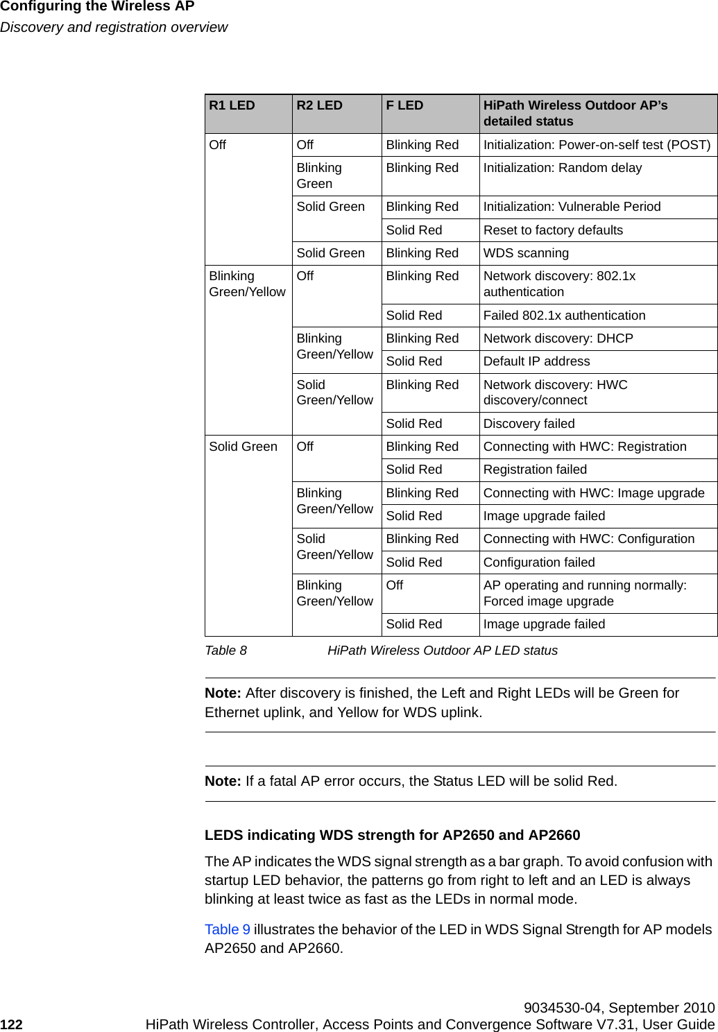

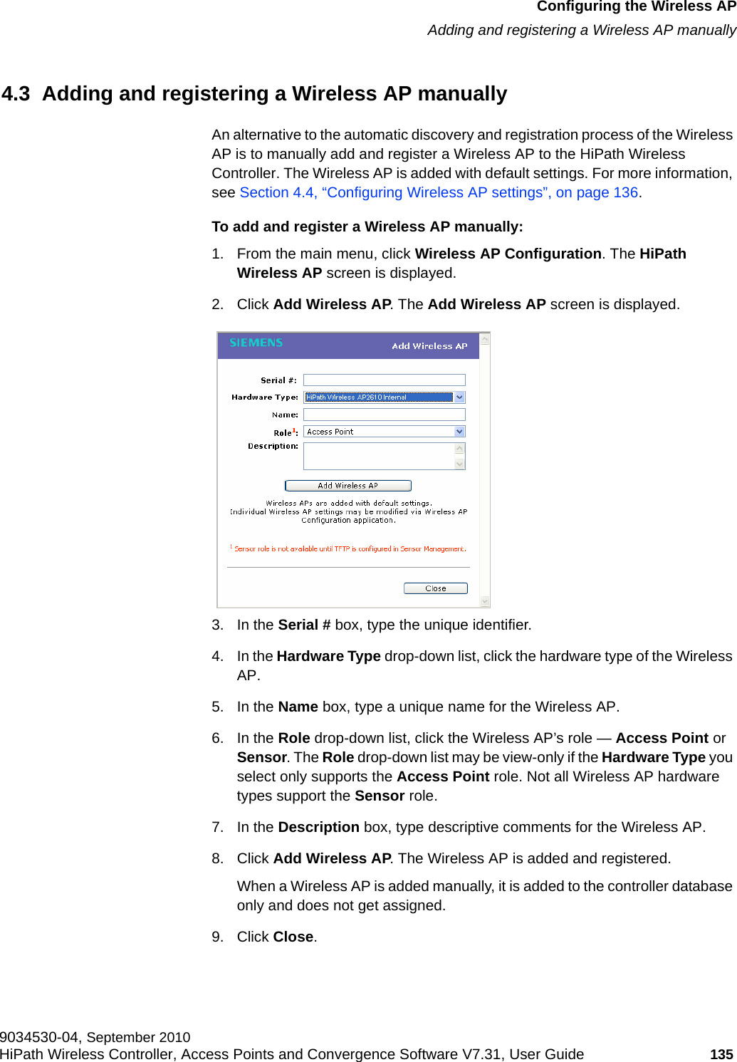

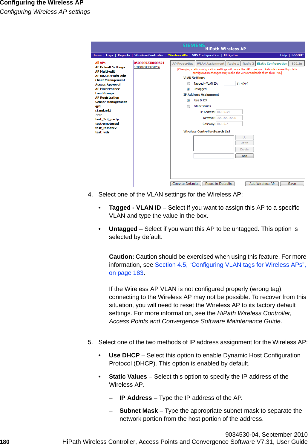
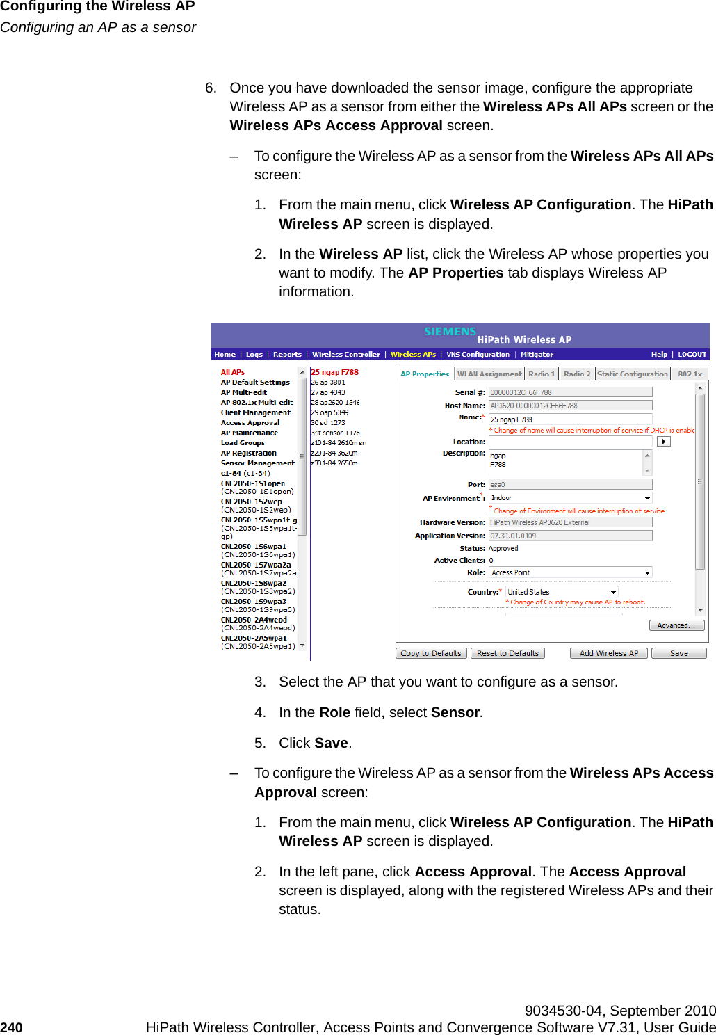
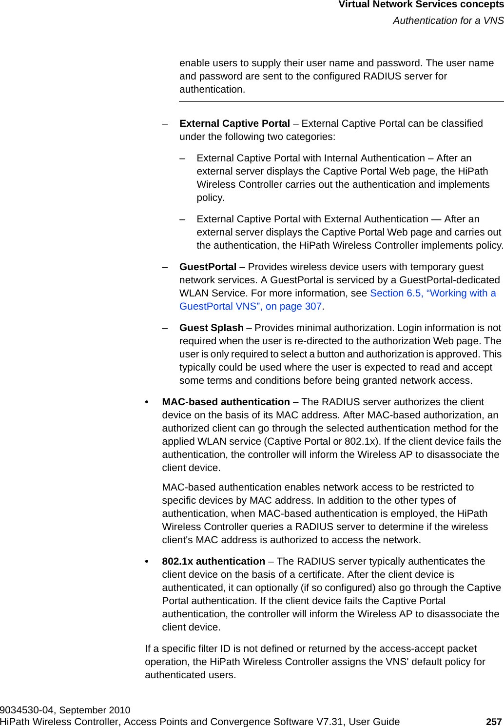
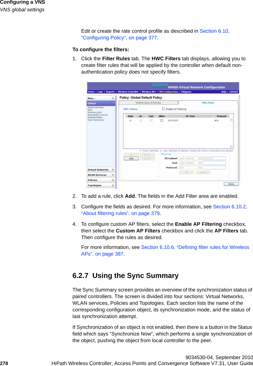
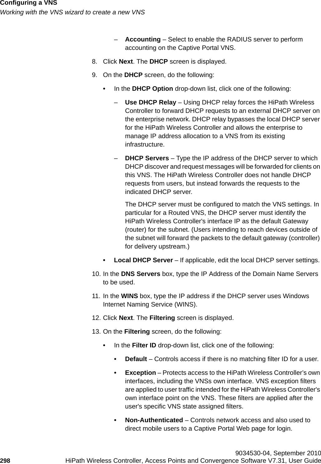
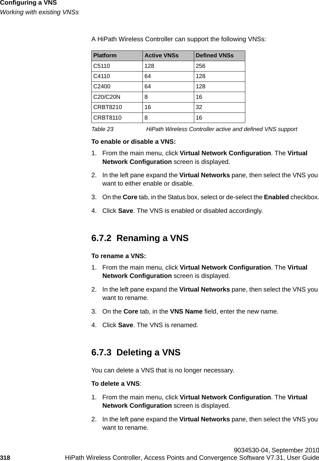
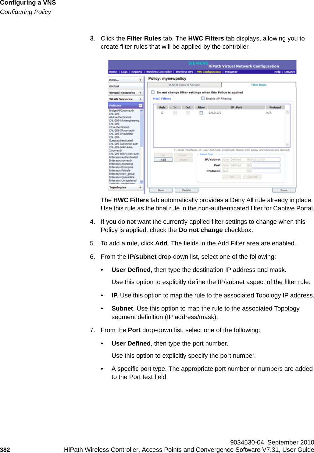
![hwc_vnsintro.fmVirtual Network Services conceptsFiltering9034530-04, September 2010HiPath Wireless Controller, Access Points and Convergence Software V7.31, User Guide 261 • Authentication by 802.1x — When authentication by 802.1x is configured, user authentication is completed using the 802.1x/EAP protocol before a user is granted access to a network resource. Therefore, the enforcement of non-authenticated traffic rules is not applicable. When authentication is returned, then the filter ID determines what Policy, and therefore filters, are applied to the user.The following is a high-level description of how HiPath Wireless Controller filters traffic:1. The HiPath Wireless Controller attempts to match each packet of a VNS to the filtering rules (that is, Policy) that apply to the wireless device user.2. If a filtering rule is matched, the operation to allow or deny is executed.3. The next packet is fetched for filtering.5.6.3 Legacy compatibility with Policy-based filtering and VNS assignmentPrior to V7.0, policy re-assignments were made through the return of special attributes in the RADIUS Accept message. These attributes included:•“Login-Lat-Group” and “Tunnel-Private-Group-ID” to assign the user to a child VNS context•“Filter ID” to assign the user to a specified Filter Group.At V7.0, the upgrade process converts and generates the necessary relationships for all elements of a VNS.Each Filter Group definition for a VNS becomes a new Policy, with the Policy name determined by VNS hierarchy. The Policy name is created by adding the internal context to the RADIUS-returned attributes. For example:Policy name = <parent VNS>[ :<Login-Lat-Group>] : FilterID | “Default”The child VNS concept is deprecated, with child VNSs becoming just pure Policy definitions, assigned by the authentication action.The RADIUS client or Security Manager applies legacy decision rules to pick the correct Policy name if the “Restrict Policy Set” feature is selected for the VNS.](https://usermanual.wiki/Extreme-Networks/OAP36B.User-Manual-I/User-Guide-1395763-Page-261.png)
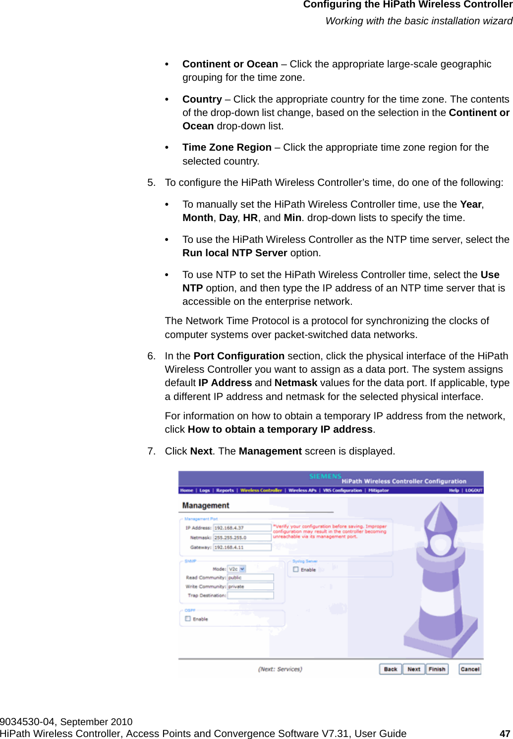
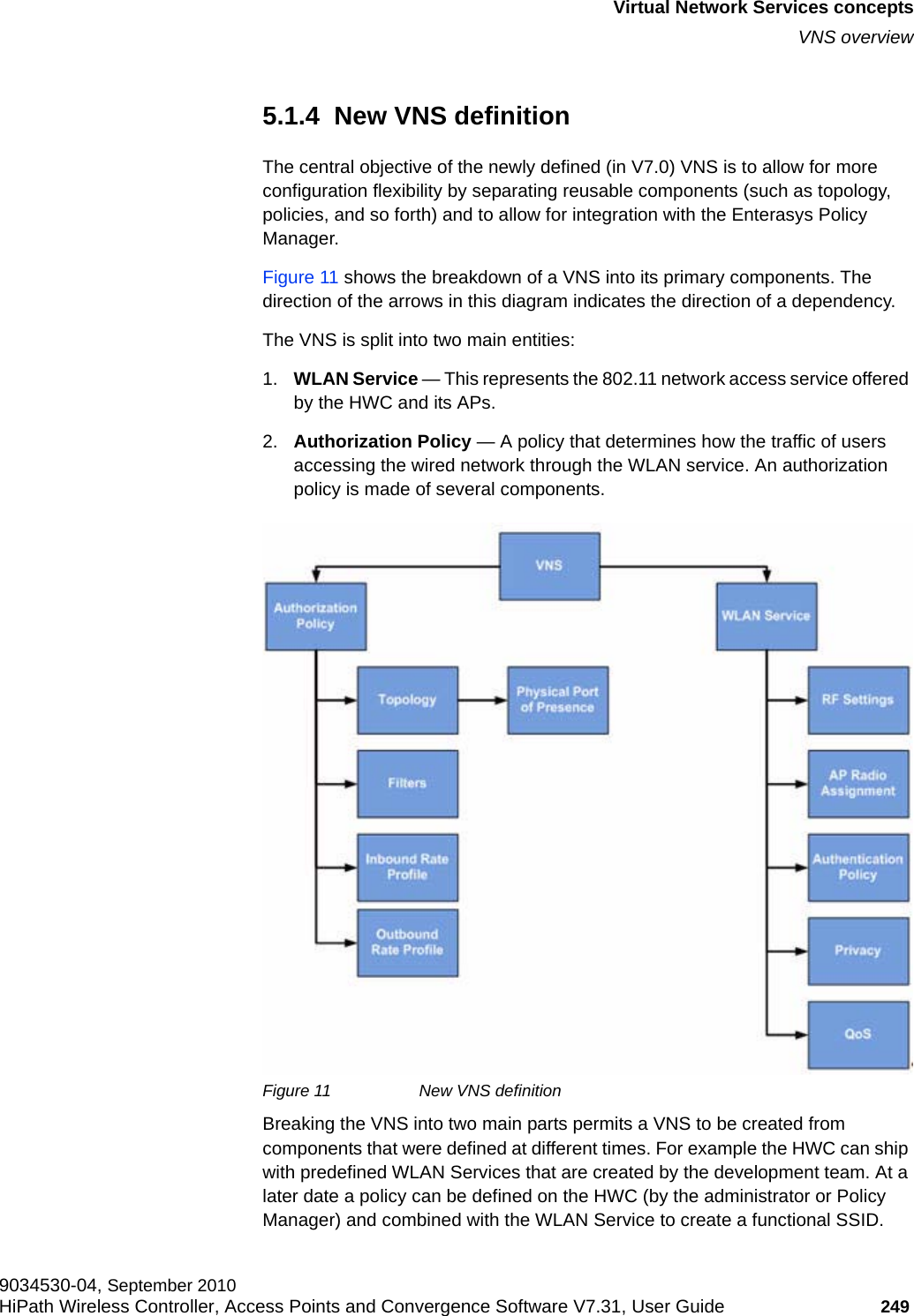
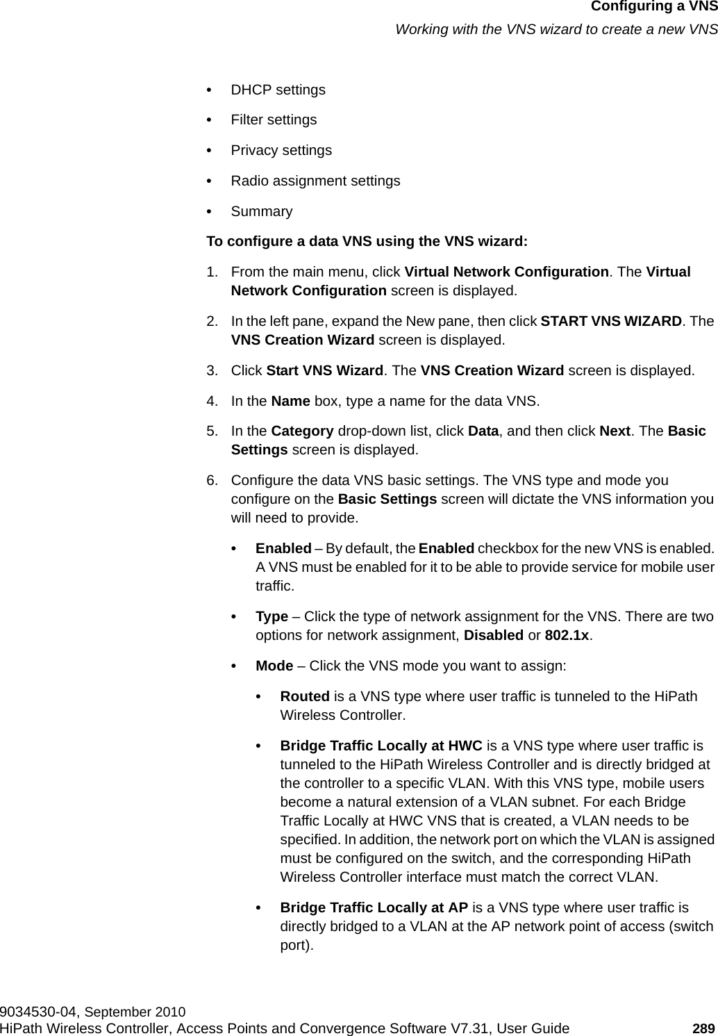
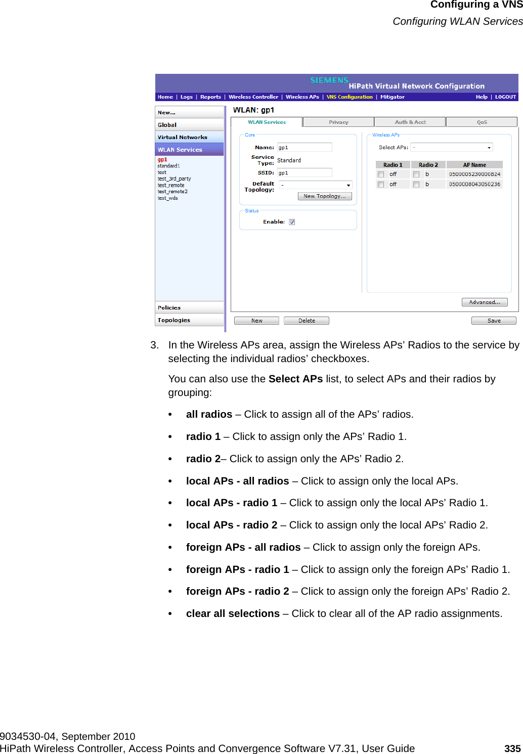
![Configuring a VNShwc_vnsconfiguration.fmHigh level VNS configuration flow 9034530-04, September 2010266 HiPath Wireless Controller, Access Points and Convergence Software V7.31, User Guide You can use the VNS Creation Wizard to guide you through the necessary steps to create a virtual network service (and the necessary subcomponents during the process). The end result is a fully resolved set of elements and an active service.The recommended order of configuration events is:1. Before you begin, draft out the type of services the system is expected to provide – wireless services, encryption types, infrastructure mapping (VLANs), and connectivity points (switch ports). Switch port VLAN configuration/trunks must match the controller's.2. Set up basic controller services such as NTP, Routing, DNS, and RADIUS Servers, using one of the following methods:•Run the Basic Configuration Wizard, or•Manually define the necessary infrastructure components such as RADIUS Servers. RADIUS Servers are defined via the VNS Configuration > Global > Authentication tab.3. Define Topologies. Topologies represent the controller’s points of network attachment. Therefore, VLANs and port assignments need to be coordinated with the corresponding switch ports.4. Define Policies. Policies are typically bound to Topologies. Policy application assigns user traffic to the corresponding network point of attachment.•Policies define mobile user access rights by filtering.•Polices reference the mobile user's traffic rate control profiles. 5. Define the WLAN Service.•Define SSID and privacy settings for the wireless link. •Select the set of APs and Radios on which the service is present.•Configure the method of credential authentication for wireless users (None, Internal CP, External CP, GuestPortal, 802.1x[EAP]). 6. Create a VNS that binds the WLAN Service to the Policy that will be used for default assignment upon user network attachment. The VNS configuration page in turn allows for in-place creation of any dependencies it may require. For example:•Create a new WLAN Service.•Create a new Policy.– Create a new Topology.– Create new ingress and egress rate control policies.](https://usermanual.wiki/Extreme-Networks/OAP36B.User-Manual-I/User-Guide-1395763-Page-266.png)
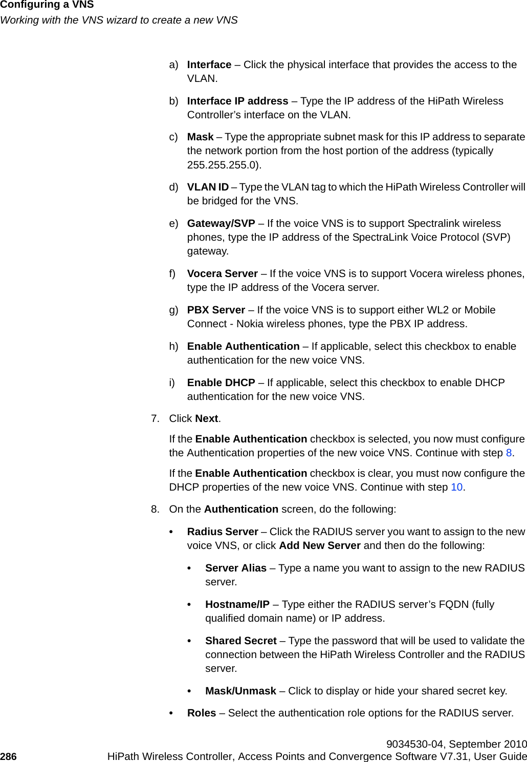
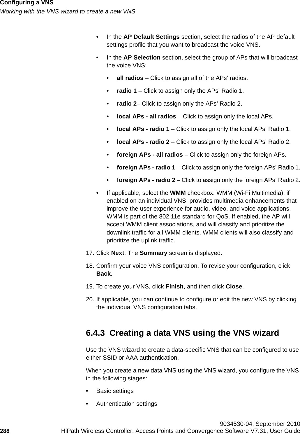
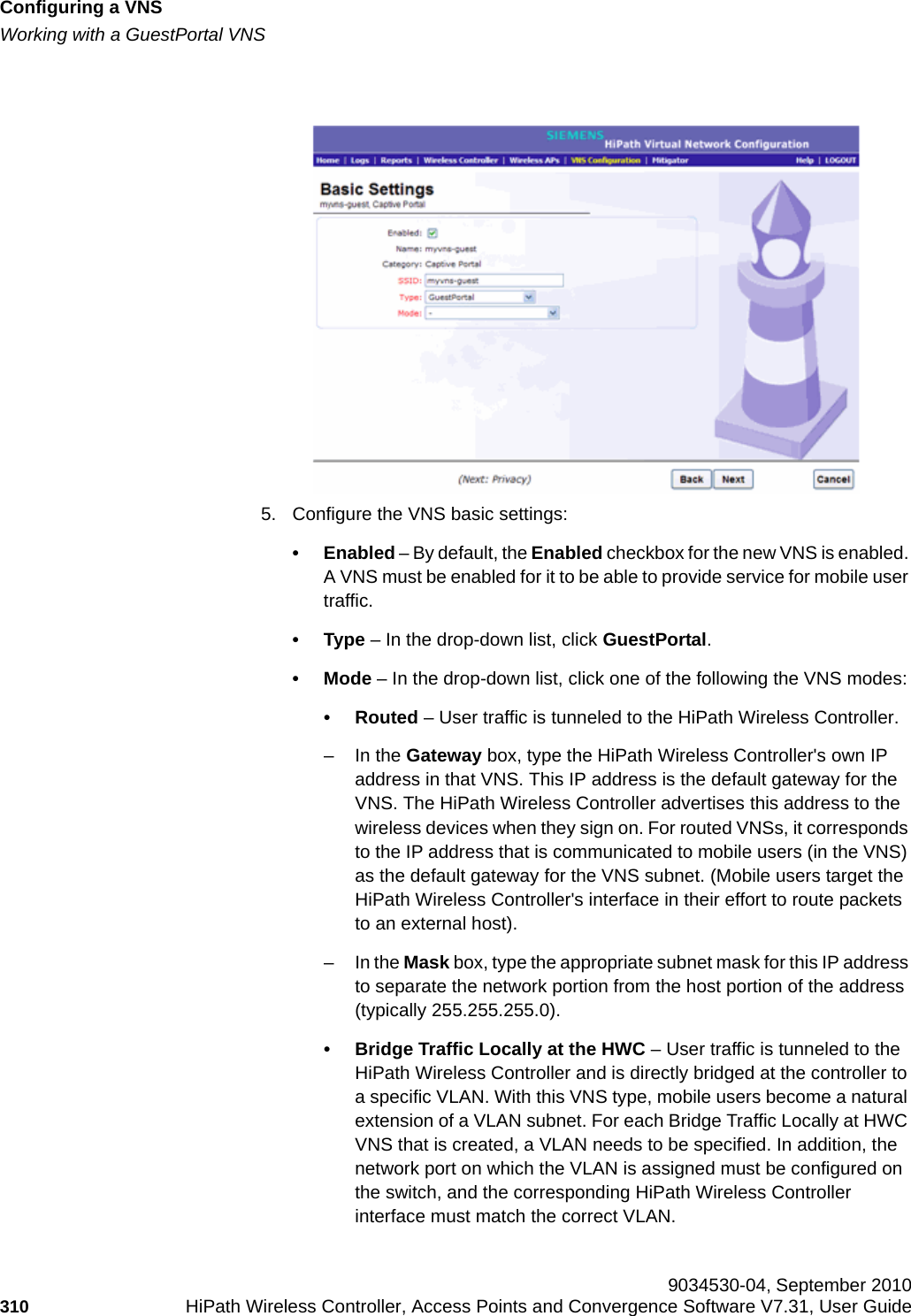
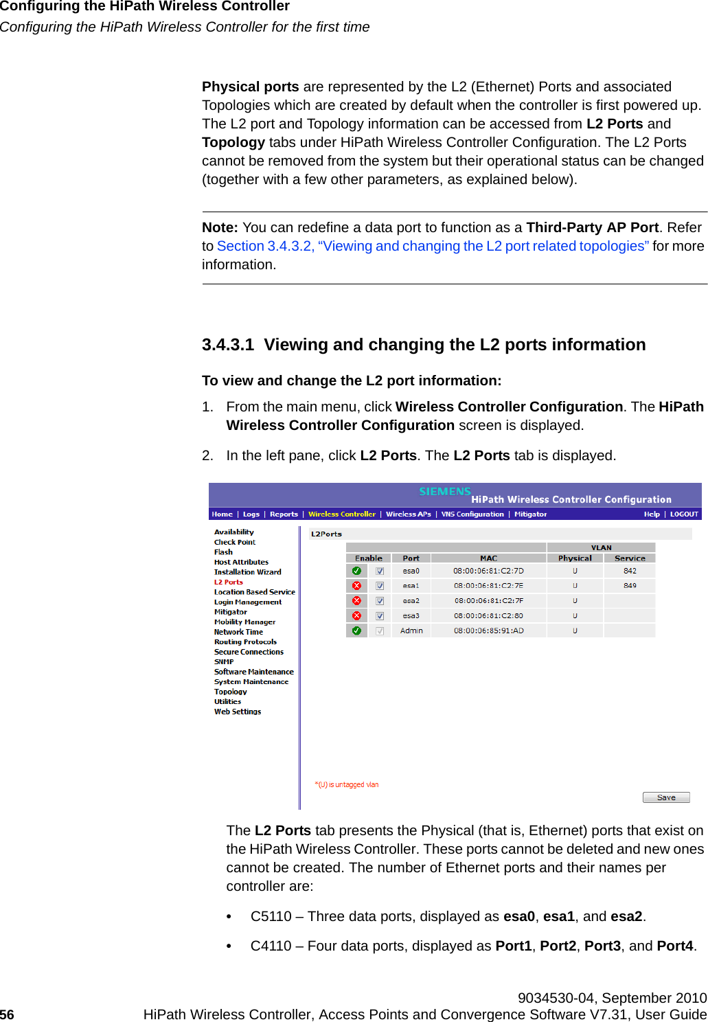
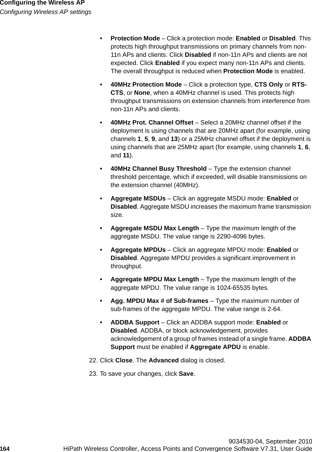
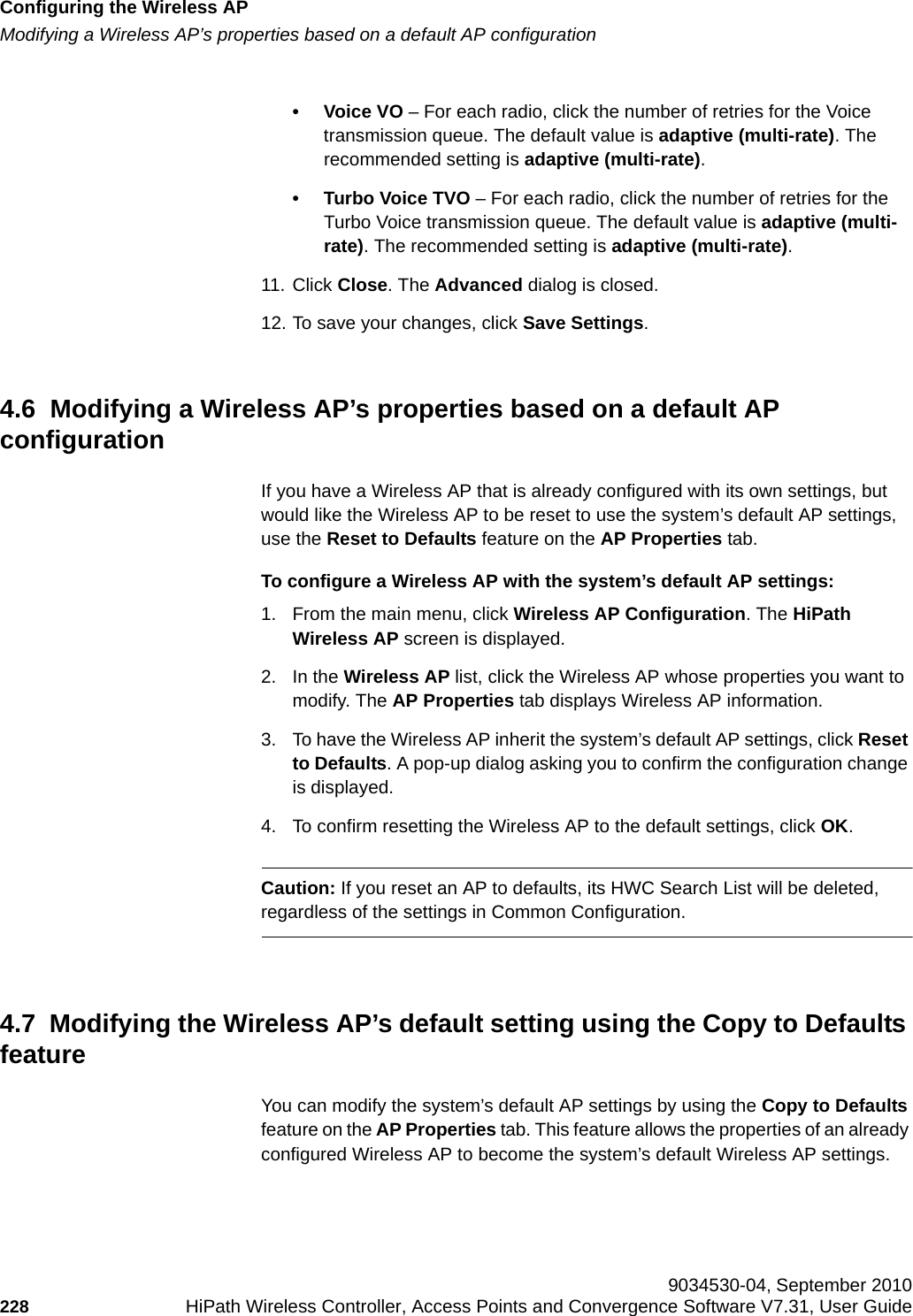
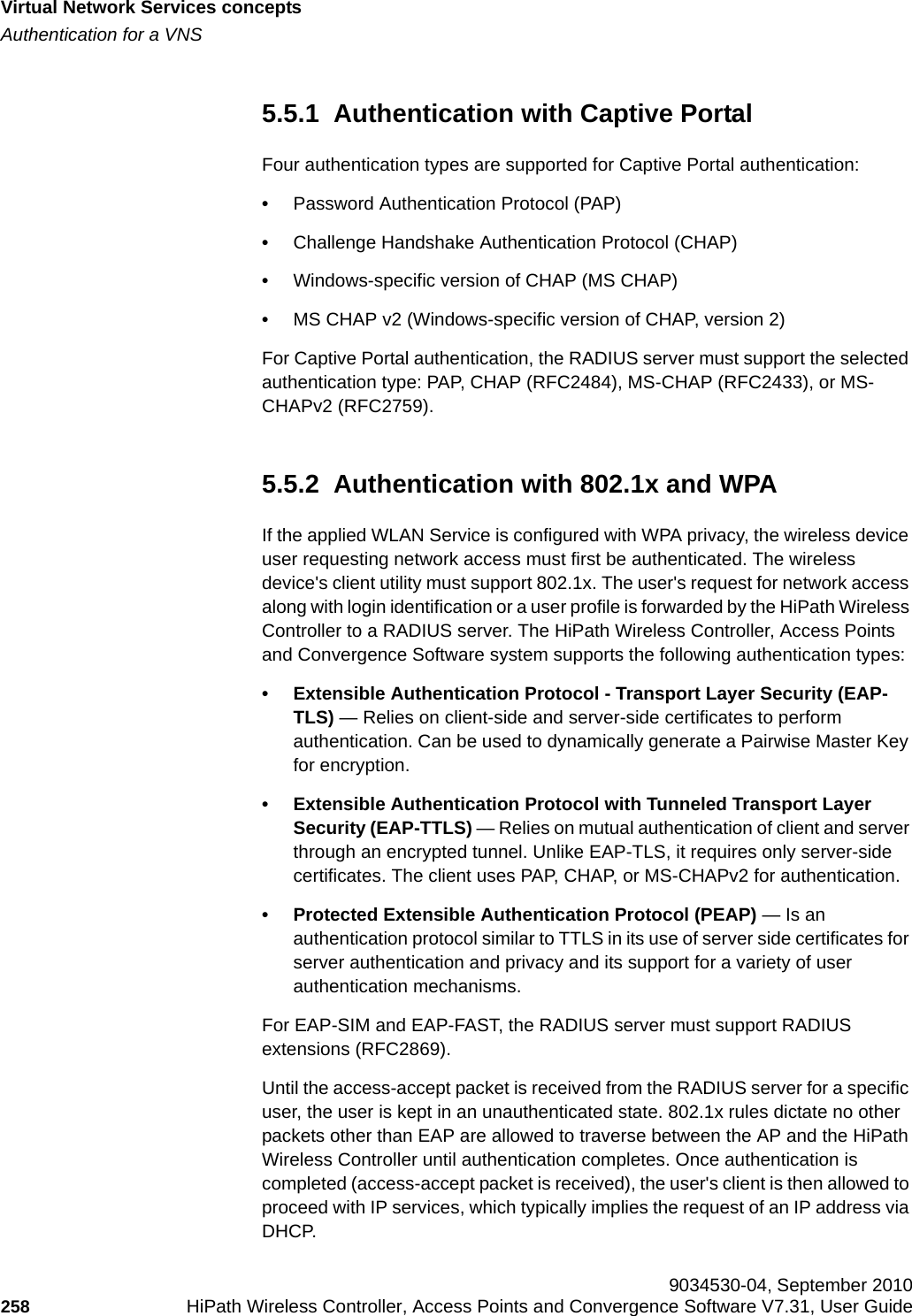
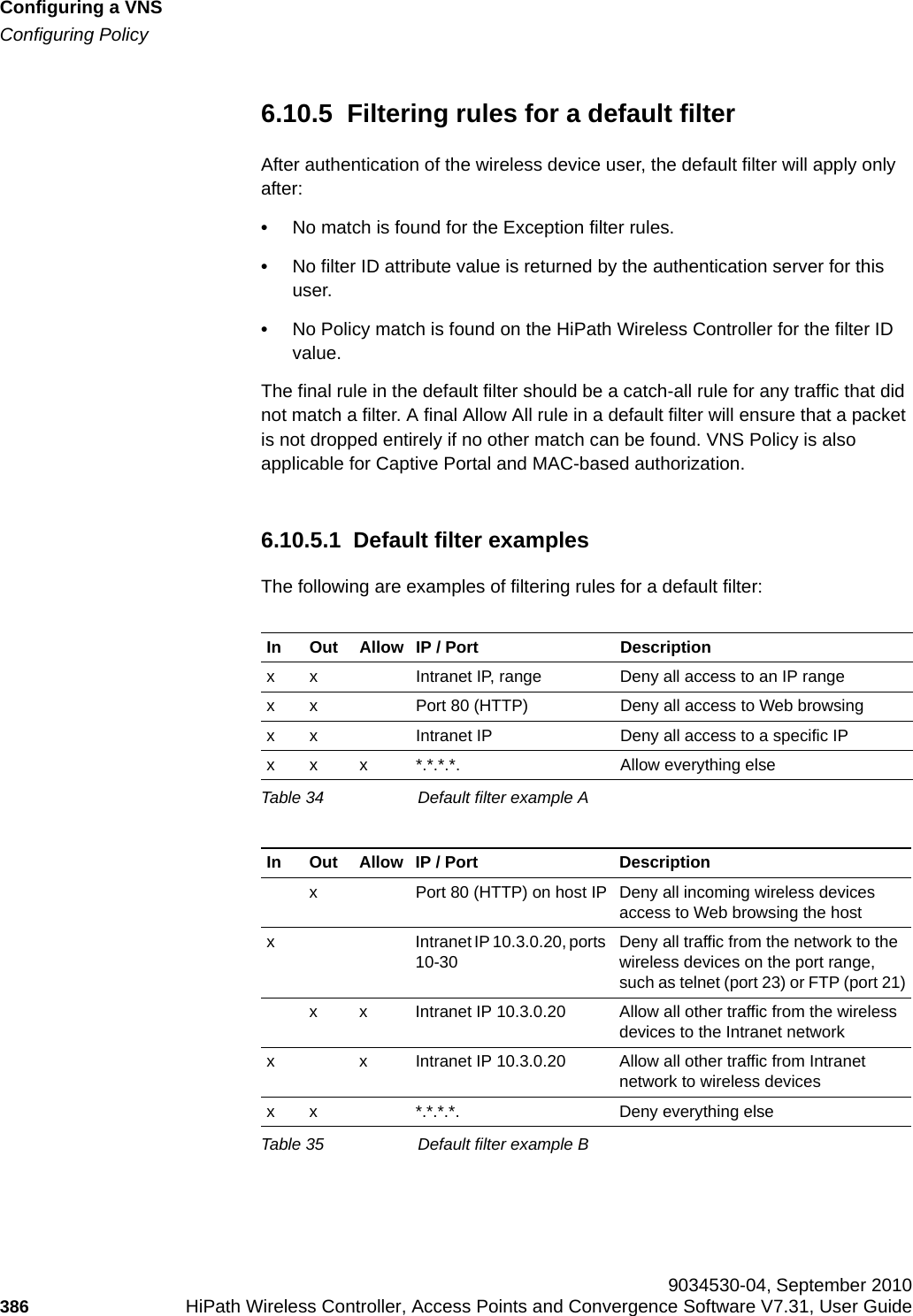
![Configuring a VNShwc_vnsconfiguration.fmConfiguring Policy 9034530-04, September 2010384 HiPath Wireless Controller, Access Points and Convergence Software V7.31, User Guide 6.10.3.1 Non-authenticated filter examplesA basic non-authenticated filter for internal Captive Portal should have three rules, in the following order:Note: For external Captive Portal, an additional rule to Allow (in/out) access to the external Captive Portal authentication/Web server is required.If you place URLs in the header and footer of the Captive Portal page, you must explicitly allow access to any URLs mentioned in the authentication's server page, such as:• Internal Captive Portal – URLs referenced in a header or footer• External Captive Portal – URLs mentioned in the page definitionHere is another example of a non-authenticated filter that adds two more filtering rules. The two additional rules do the following: •Deny access to a specific IP address.•Allows only HTTP traffic.In Out Allow IP / Port Descriptionx x x IP address of default gateway (VNS Interface IP)Allow all incoming wireless devices access to the default gateway of the VNS.x x x IP address of the DNS Server Allow all incoming wireless devices access to the DNS server of the VNS.x x *.*.*.* Deny everything else.Table 30 Non-authenticated filter example AIn Out Allow IP / Port Descriptionx x x IP address of the default gateway Allow all incoming wireless devices access to the default gateway of the VNS.x x x IP address of the DNS Server Allow all incoming wireless devices access to the DNS server of the VNS.x x [a specific IP address, or address plus range] Deny all traffic to a specific IP address, or to a specific IP address range (such as:0/24).x x x *.*.*.*:80 Allow all port 80 (HTTP) traffic.x x *.*.*.* Deny everything else. Table 31 Non-authenticated filter example B](https://usermanual.wiki/Extreme-Networks/OAP36B.User-Manual-I/User-Guide-1395763-Page-384.png)
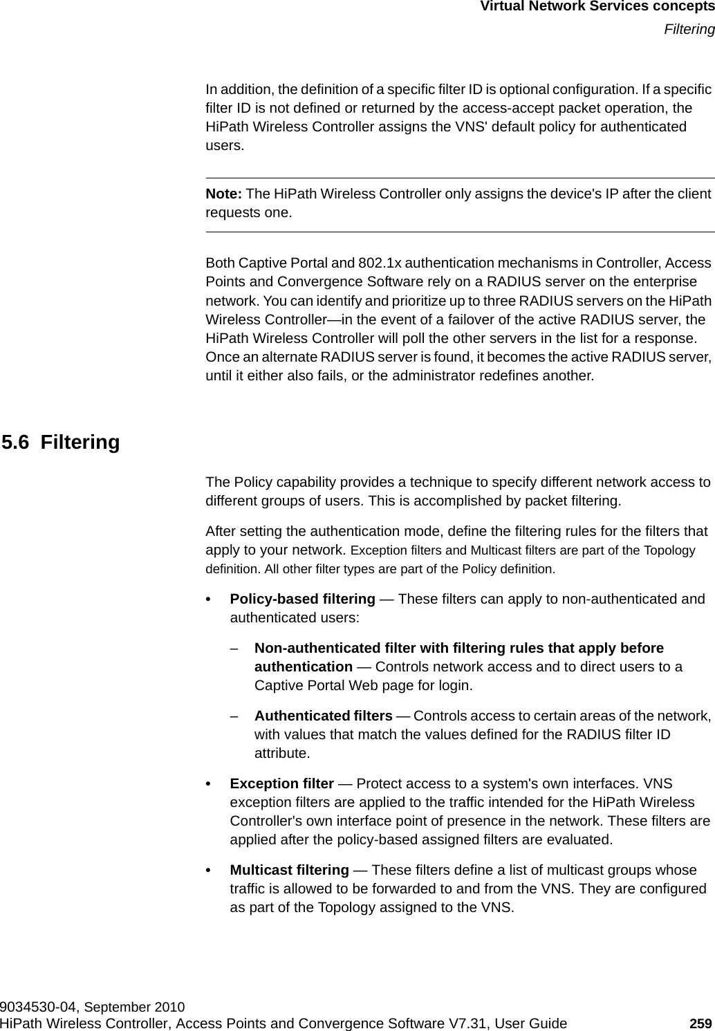
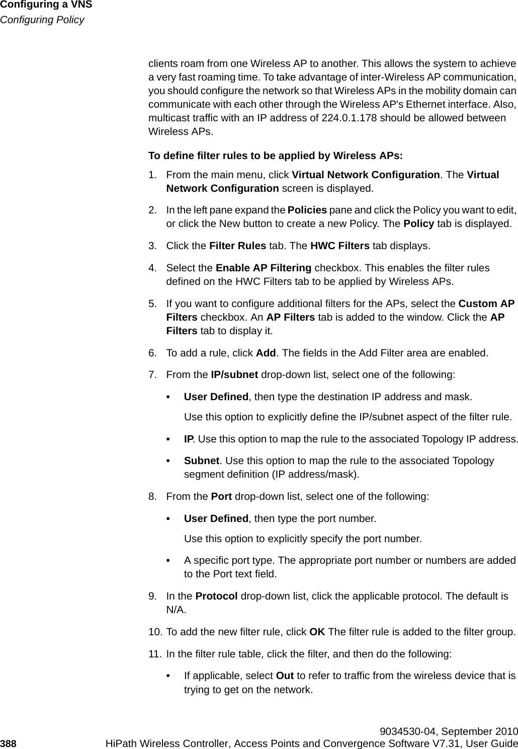
![hwc_vnsconfiguration.fmConfiguring a VNSConfiguring Policy9034530-04, September 2010HiPath Wireless Controller, Access Points and Convergence Software V7.31, User Guide 385 Once a wireless device user has logged in on the Captive Portal page, and has been authenticated by the RADIUS server, then the following filters will apply:• Policy filters – If a filter ID associated with this user was returned by the authentication server, then the Policy with the same name as the filter ID will be applied.• Default filter – If no matching filter ID was returned from the authentication server.6.10.3.2 Authenticated filter examplesBelow are two examples of possible filtering rules for authenticated users. The first example disallows some specific access before allowing everything else.The second example does the opposite of the first example. It allows some specific access and denies everything else. 6.10.4 ICMP Type enforcementICMP filter rules can now be constrained to ICMP type/range. You can define the ICMP type/range in the Port field using the TCP/UDP port definition nomenclature. That is, define the rule as a normal IP/subnet:port signature (10.0.0.0/24:8), where the ICMP type is entered in the Port field.This feature allows for tighter granularity over enforcement of ICMP restrictions. You can allow redirects and DF/MTU indications, and deny ICMP Echo (pings) for users.In Out Allow IP / Port Descriptionx x *.*.*.*:22-23 SSH and telnet sessionsx x [specific IP address, range] Deny all traffic to a specific IP address or address rangex x x *.*.*.*. Allow everything elseTable 32 Filtering rules example AIn Out Allow IP / Port Descriptionx x x [specific IP address, range] Allow traffic to a specific IP address or address range.x x *.*.*.*. Deny everything else.Table 33 Filtering rules example B](https://usermanual.wiki/Extreme-Networks/OAP36B.User-Manual-I/User-Guide-1395763-Page-385.png)
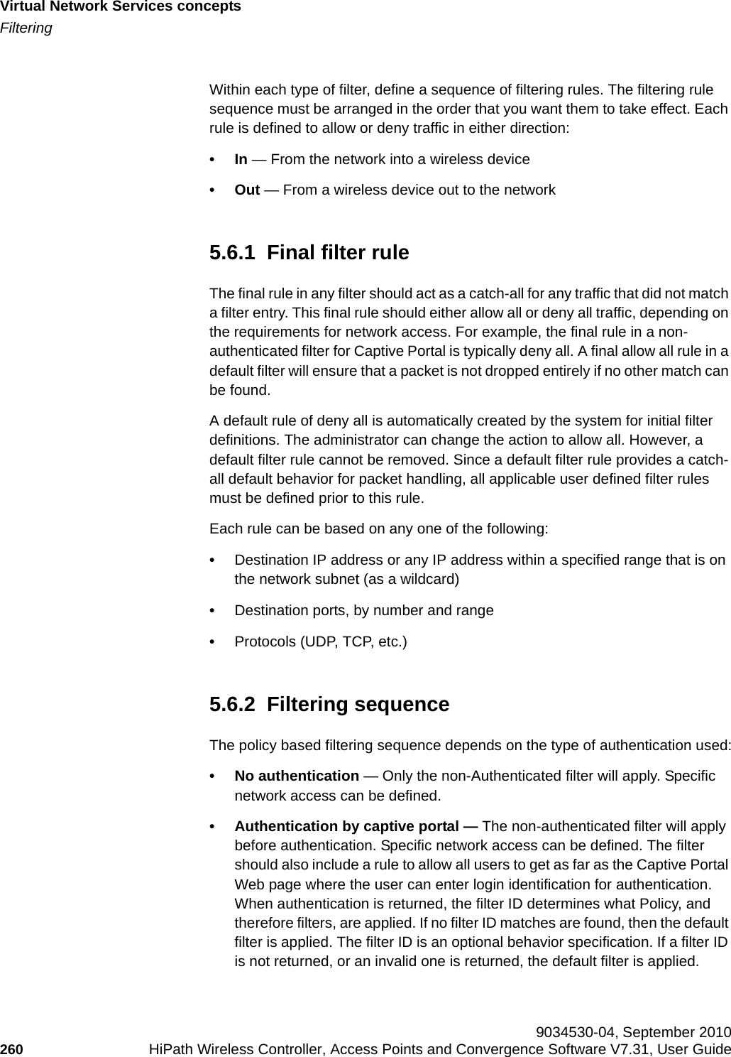
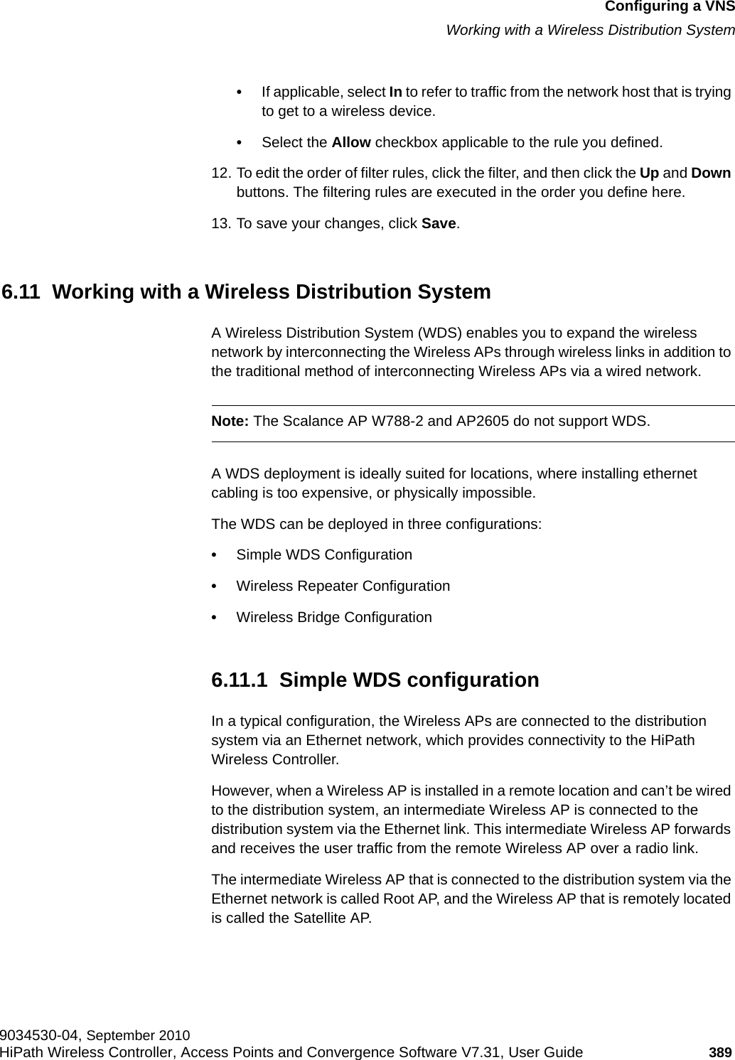
![hwc_vnsconfiguration.fmConfiguring a VNSConfiguring Policy9034530-04, September 2010HiPath Wireless Controller, Access Points and Convergence Software V7.31, User Guide 387 6.10.5.2 Filtering rules between two wireless devicesTraffic from two wireless devices that are on the same VNS and are connected to the same Wireless AP will pass through the HiPath Wireless Controller and therefore be subject to filtering policy. You can set up filtering rules that allow each wireless device access to the default gateway, but also prevent each device from communicating with each other. Add the following two rules to a filter ID filter, before allowing everything else:Note: You can also prevent the two wireless devices from communicating with each other by setting Block Mu to MU traffic. See Section 6.9.1.3, “Assigning an optional default topology to a service”, on page 333. 6.10.6 Defining filter rules for Wireless APsYou can also apply filter rules on the Wireless AP. Applying filter rules at the Wireless AP helps restrict unwanted traffic at the edge of your network. The Wireless APs can support up to a maximum of 32 filters rules per group. Filtering at the Wireless AP can be configured with the following Topology types:• Bridge Traffic Locally at the AP – If filtering at the Wireless AP is enabled on a Bridge Traffic Locally at the AP topology, the filtering is applied to traffic in both the uplink and downlink direction — the uplink direction is from the wireless device to the network, and downlink direction is from the network to the wireless device.• Routed and Bridge Traffic Locally at the HWC – If filtering at the Wireless AP is enabled on a Routed or Bridge Traffic Locally at the HWC topology, the filtering is applied only to traffic in the UL direction. The filters applied in the UL direction at the Wireless AP can be the same or different from filters applied at the HiPath Wireless Controller.Wireless AP filteringWhen filtering at the Wireless AP is enabled, Wireless APs obtain client filter information from the HiPath Wireless Controller. In addition, direct inter-Wireless AP communication allow Wireless APs to exchange client filter information as In Out Allow IP / Port Descriptionx x x [Intranet IP] Allow access to the Gateway IP address of the VNS onlyx x [Intranet IP, range] Deny all access to the VNS subnet range (such as 0/24)x x x *.*.*.*. Allow everything elseTable 36 Rules between two wireless devices](https://usermanual.wiki/Extreme-Networks/OAP36B.User-Manual-I/User-Guide-1395763-Page-387.png)
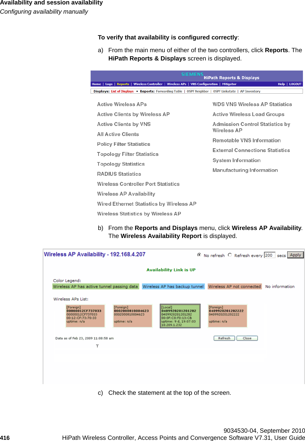
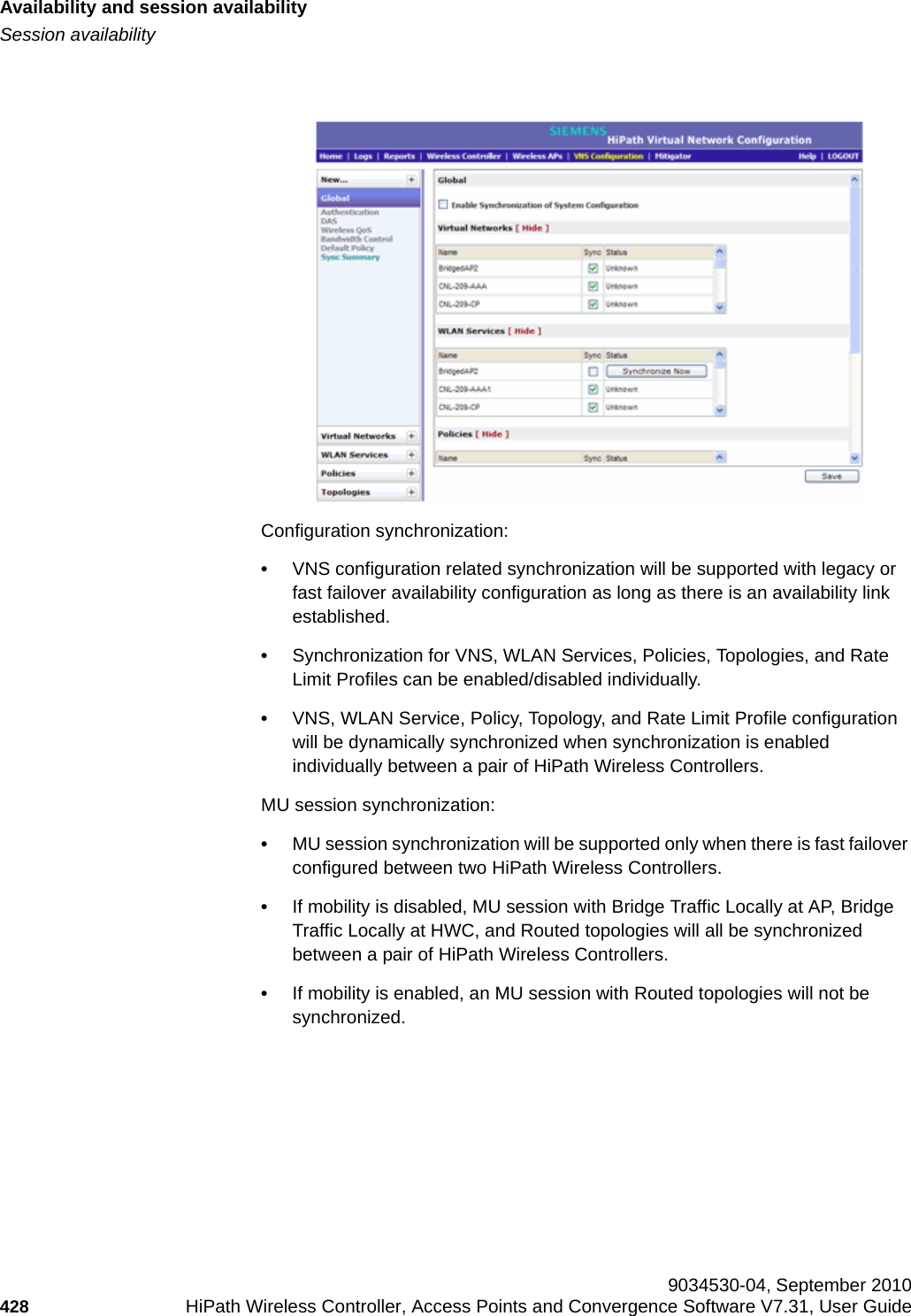
![hwc_fastfailover.fmAvailability and session availabilitySession availability9034530-04, September 2010HiPath Wireless Controller, Access Points and Convergence Software V7.31, User Guide 427 3. Check the statement at the top of the screen. If the statement reads Availability link is up, the availability feature is configured correctly. If the statement reads Availability link is down, check the configuration error in logs. For more information on logs, see the HiPath Wireless Controller, Access Points and Convergence Software Maintenance Guide.7.4.2.3 Verify synchronizationTo verify that all elements have been synchronized correctly, navigate to the VNS tab on both the primary and secondary HiPath Wireless Controllers, and confirm that the topologies, WLAN services, policies and desired VNSs aredisplayed as [synchronized]. You can verify this by selecting the appropriate tabs and then inspecting the Synchronized flags or by navigating to VNS Configuration, Global, and then Sync Summary page.](https://usermanual.wiki/Extreme-Networks/OAP36B.User-Manual-I/User-Guide-1395763-Page-427.png)