Extreme Networks OAP36B HIPATH WIRELESS OUTDOOR ACCESS POINT User Manual
Extreme Networks, Inc. HIPATH WIRELESS OUTDOOR ACCESS POINT
UserManual.wiki
>
Extreme Networks
>
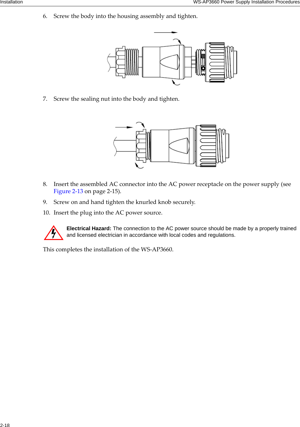
OAP36B User Manual
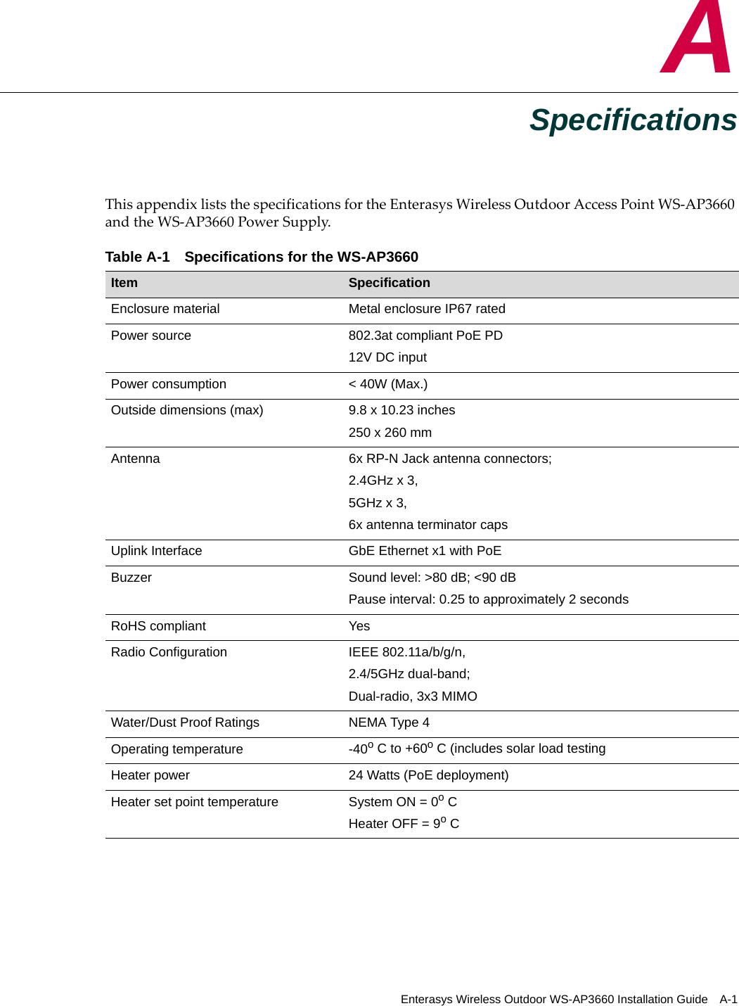
>
User Manual
Contents
1.
User Manual I
2.
User Manual II
3.
User Manual
User Manual
Navigation menu
Upload a User Manual
Namespaces
Wiki Guide
HTML
PDF
Info
Views
User Manual
Discussion / Help
Navigation

![Getting HelpEnterasys Wireless Outdoor WS-AP3660 Installation Guide xiGetting HelpFor additional support related to the WS-AP3660 or this document, contact Enterasys Networks using one of the following methods:Before contacting Enterasys Networks for technical support, have the following data ready:• Your Enterasys Networks service contract number• A description of the failure• A description of any action(s) already taken to resolve the problem (for example, changing mode switches or rebooting the unit)• The serial and revision numbers of all involved Enterasys Networks products in the network• A description of your network environment (such as layout, cable type, other relevant environmental information)• Network load and frame size at the time of trouble (if known)• The device history (for example, if you have returned the device before, or if this is a recurring problem)• Any previous Return Material Authorization (RMA) numbersWorld Wide Web www.enterasys.com/support/ Phone 1-800-872-8440 (toll-free in U.S. and Canada) or 1-978-684-1000For the Enterasys Networks Support toll-free number in your country:www.enterasys.com/support/Internet mail support@enterasys.comTo expedite your message, please type [Wireless] in the subject line.](https://usermanual.wiki/Extreme-Networks/OAP36B.User-Manual/User-Guide-1736852-Page-13.png)