Ezurio 05W Wireless LAN Module User Manual SDS WI001 XvY
Ezurio Ltd Wireless LAN Module SDS WI001 XvY
UserManual.wiki
>
Ezurio
>
05W User Manual
>
user manual
Contents
1.
user manual
2.
regulatory information to be included
3.
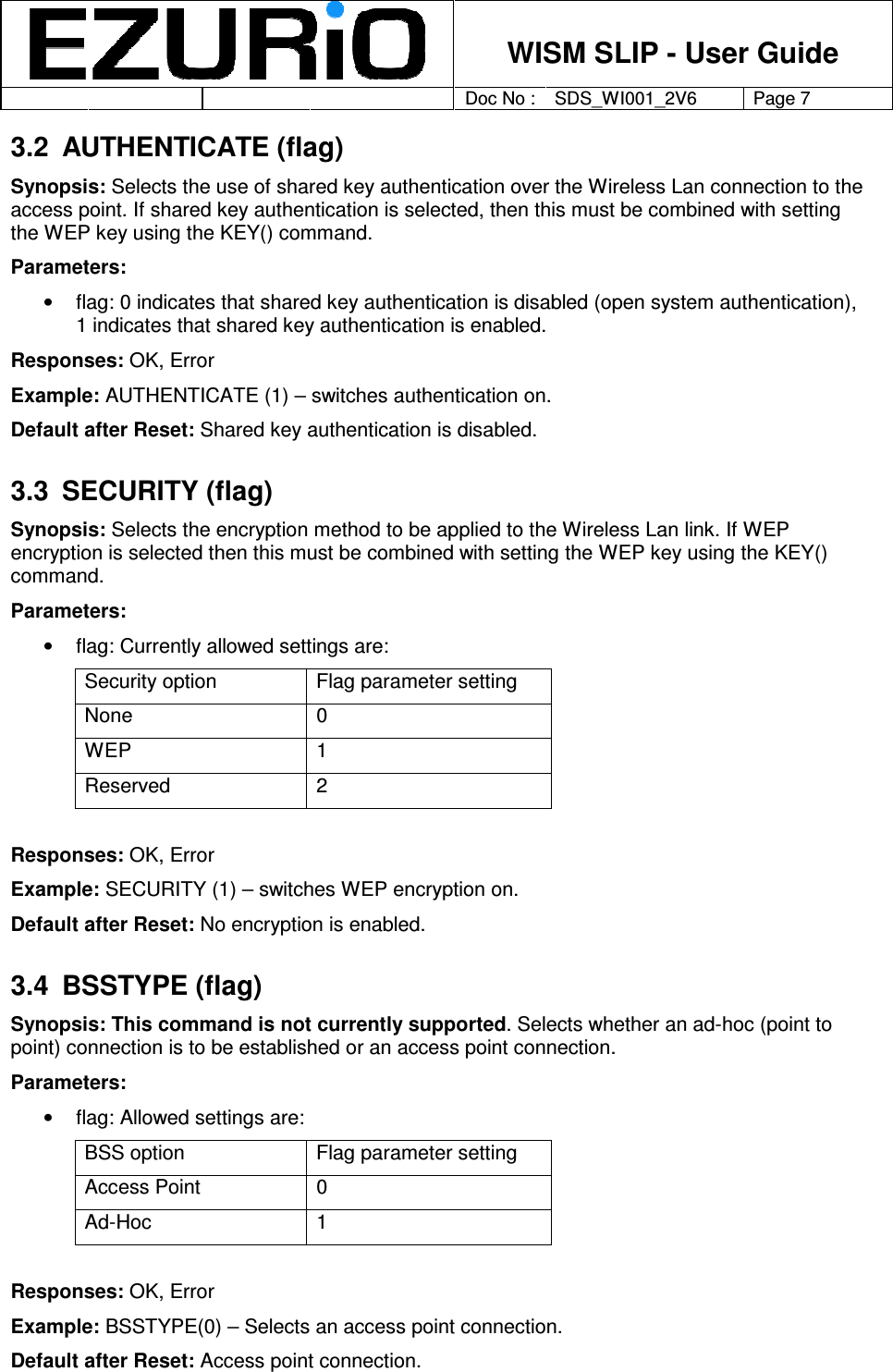
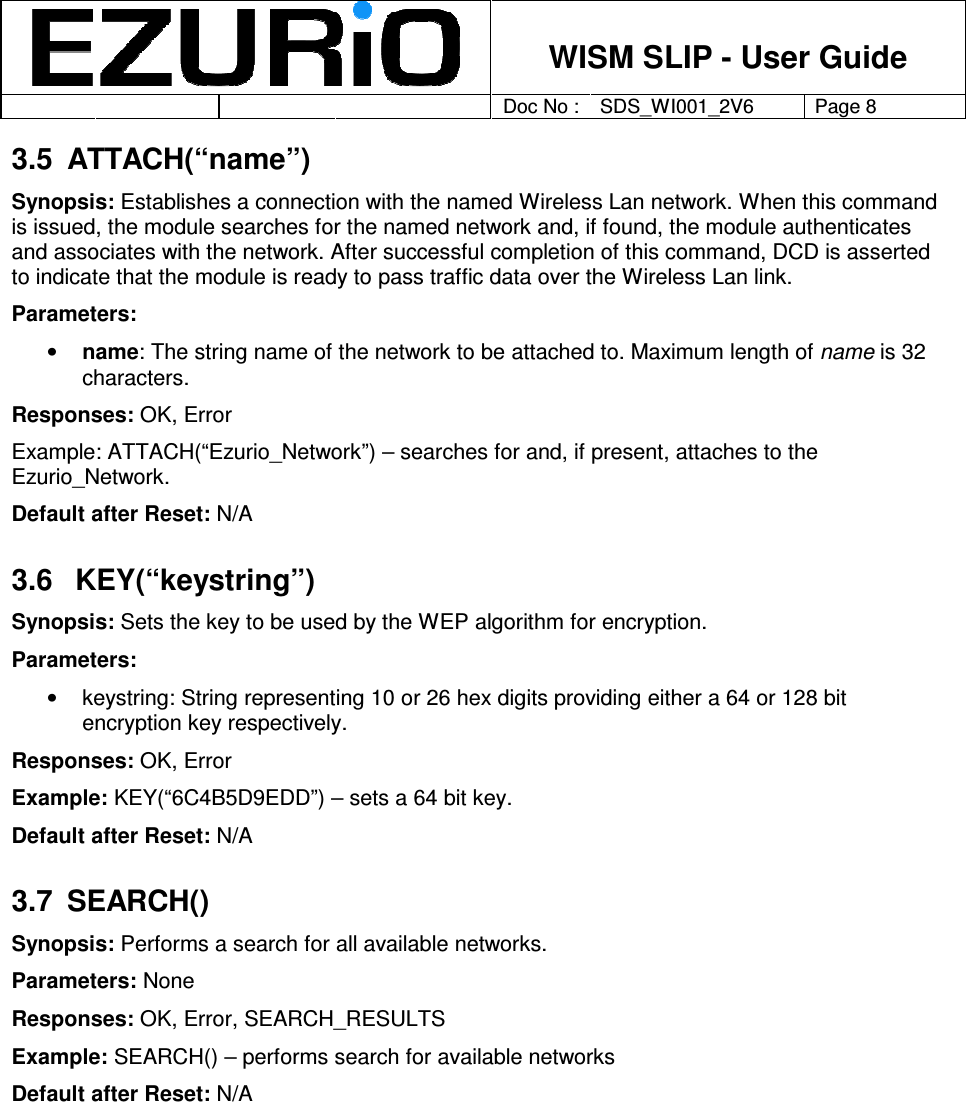
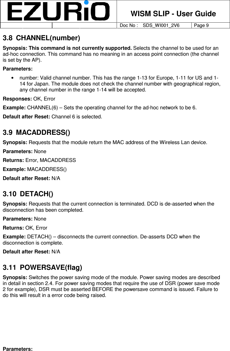
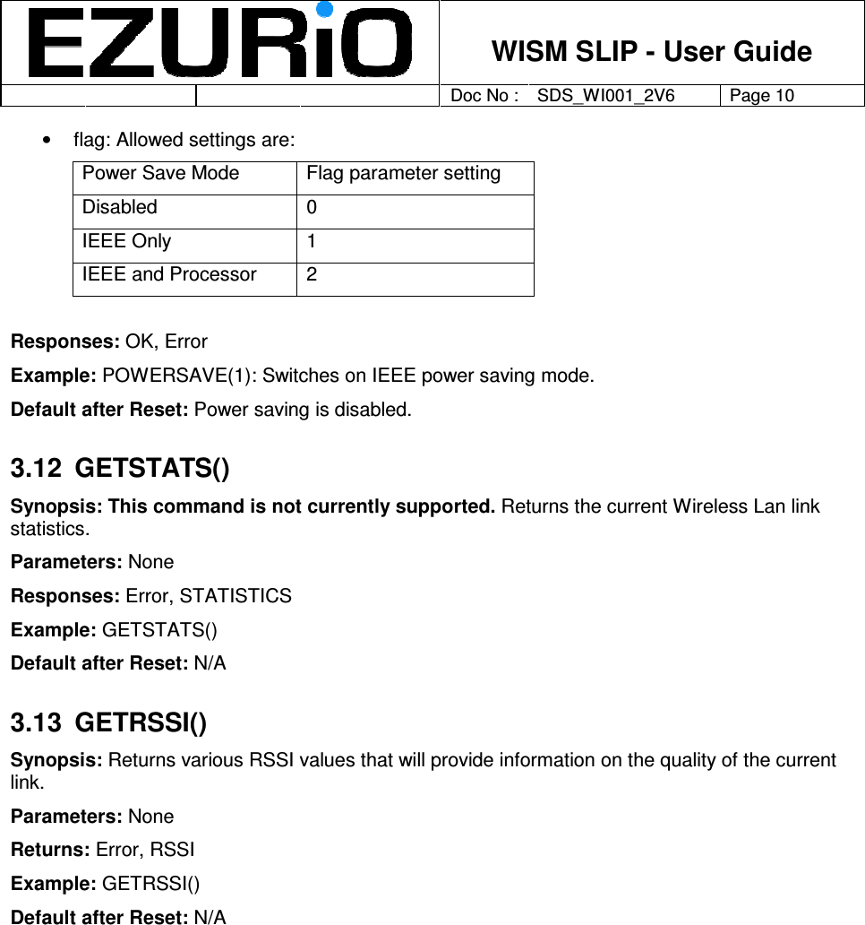
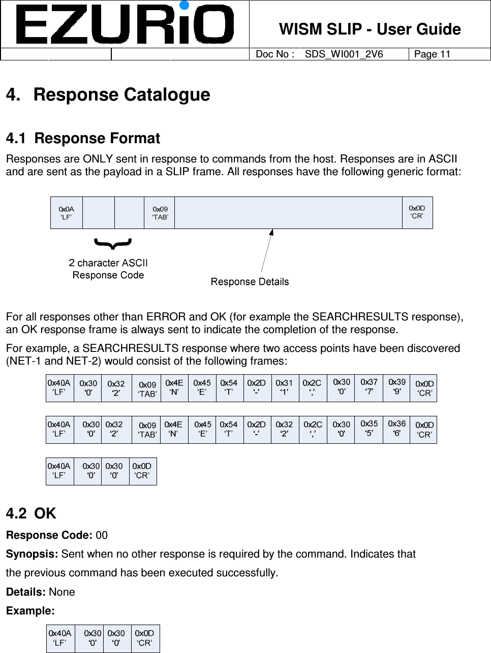
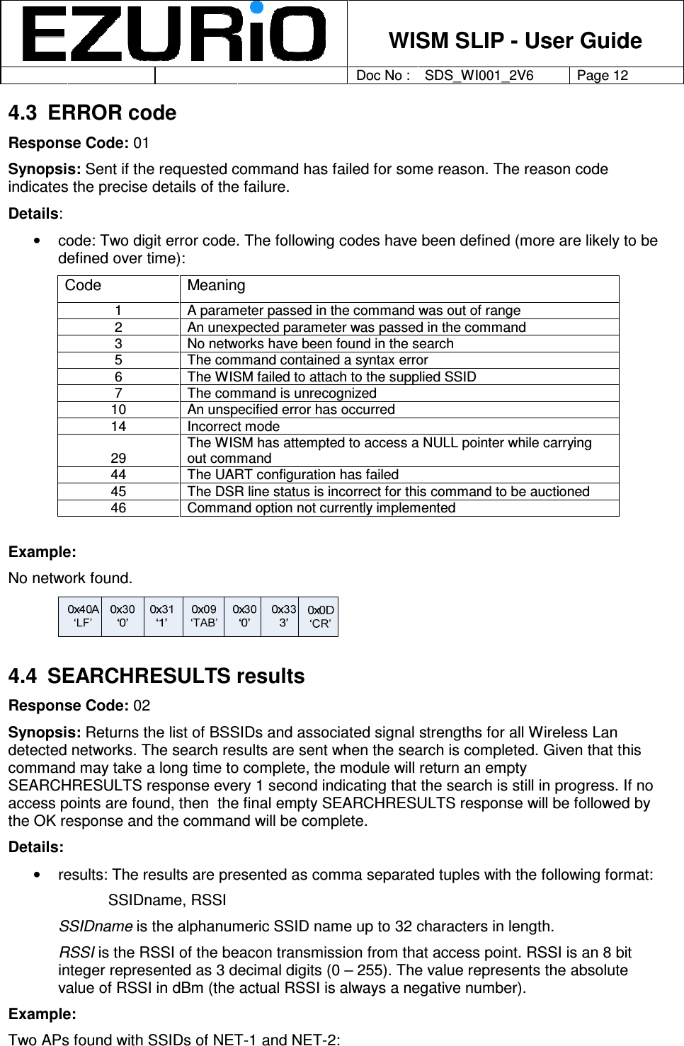
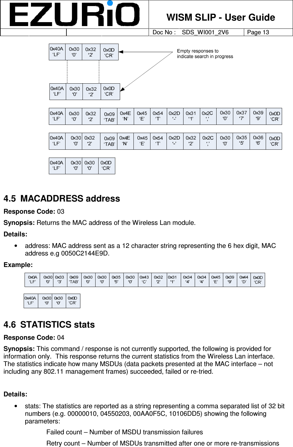
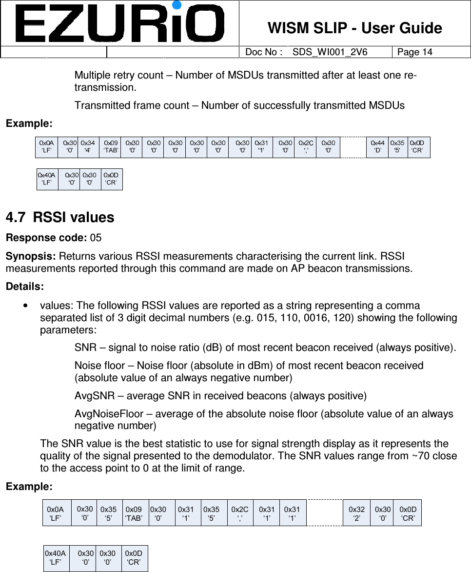
User manual
4.
user manual 2
user manual
Navigation menu
Upload a User Manual
Namespaces
Wiki Guide
HTML
PDF
Info
Views
User Manual
Discussion / Help
Navigation