Ezurio 520B Bluetooth Multi-Media Module User Manual Manual
Ezurio Ltd Bluetooth Multi-Media Module Manual
Ezurio >
Contents
Manual
BTM520/521
DATA MODULE
USER MANUAL
Innovative Technology
for a Connected World
www.lairdtech.com
2
www.lairdtech.com
Laird Technologies
BTM520/521
Bluetooth® Multimedia Plus Module
CONTENTS
BTM520/521 Bluetooth® Module ..3
Overview .............................................. 3
BTM520/521 Key Features ................... 3
Specications ................................5
Detailed Specications ......................... 5
Pin Out ................................................. 6
Operating Parameters ...................9
Voltage Specications .......................... 9
Notes ................................................. 10
Conguring the BTM520/521 ......11
References ......................................... 11
Glossary of Terms ............................... 12
AT Command Set .............................. 13
Assumptions ...................................... 13
Commands ........................................ 13
General AT Commands ..................... 13
General Bluetooth® Control ............... 24
Hardware Unit Control ....................... 30
Bluetooth® Proles ............................. 32
Secure Simple Pairing ......................... 39
Link Key Management ....................... 39
Miscellaneous...................................... 40
Appendix ........................................... 41
BT-MM+ Unsolicited Messages .......... 41
BT-MM+ Error Responses ................... 41
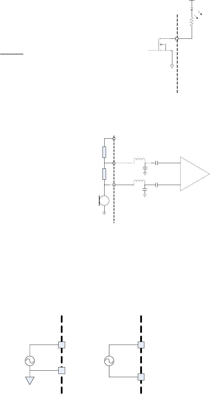
Mechanical Drawings ..................43
Mechanical Details ............................. 43
Recommended PCB Footprint ............ 43
Diagrams ............................................ 44
Ordering Information ..................47
Product Part Numbers ........................ 47
General Comments ............................ 47
TABLE OF
CONTENTS
3
www.lairdtech.com
Laird Technologies
BTM520/521
Bluetooth® Multimedia Plus Module
The BTM520 and BTM521 are the most advanced low power, multimedia Bluetooth
modules on the market. They have been designed by Laird Technologies to meet the needs
of developers who require the ultimate Bluetooth audio performance and exibility, along
with fast time to market. The modules include everything needed for a fully qualied
and functional Bluetooth multimedia application. As well as providing best in class radio
performance, range and power consumption, they support all of the functionality to run
Cambridge Silicon Radio’s Road Tunes and Blue Tunes development environments. They
support the latest Bluetooth Version 2.1+EDR Specication, providing the important advantage
of Secure Simple Pairing, which improves security and enhances the ease of use for end
customers. The BTM521, with an integrated high performance multilayer ceramic antenna
can achieve open eld ranges in excess of 300 metres.
The modules include a 16 bit stereo codec and microphone input to support both stereo and
mono applications, with the ability to drive 16Ω stereo speakers. They also contain all of
the necessary audio ltration and biasing components, so that the module only requires the
addition of speakers, microphone and push buttons to make a complete implementation.
The modules contain a full, integrated Bluetooth stack along with SPP, HFP 1.5, HSP, AVRCP
and A2DP proles, all of which have been qualied, so that no further Bluetooth qualication
is required. For users with more complex applications, additional proles will be available for
le transfer, object exchange, dial up networking, messaging and phone book control. Future
support also includes the Health Device Prole, making this the ideal module for development
of Continua compliant medical devices. Because these modules are pre-qualied, customers
using these modules can list and promote their products on the Bluetooth website free of
charge.
The BTM520 and BTM 521 modules include an embedded 32 bit, 64 MIPS DSP core within
the BC05, which is integrated with the Bluetooth functionality and which allows designers
to add signicant product enhancements. These include features such as echo cancellation,
noise reduction and audio enhancement using additional soft codecs. 16MB of ash memory
is available within the module, so that complex functionality can be included. DSP routines are
licensable from a number of specialist partners. Typical applications for these modules include
Bluetooth headsets, Bluetooth stereo headsets, VoIP phones, automotive products, wireless
audio links and medical / healthcare devices.
To speed product development and integration, Laird Technologies has developed a
comprehensive AT command interface, which simplies application development and includes
support for audio and headset functionality. It provides access to GPIO pins, allowing these
to be mapped for direct connection to actuator buttons on headsets. Combined with a low
cost developer’s kit, this ensures that the choice of Laird Technologies Bluetooth modules
guarantees the fastest route to market.
OVERVIEW AND
KEY FEATURES

4
www.lairdtech.com
Laird Technologies
BTM520/521
Bluetooth® Multimedia Plus Module
FEATURES
• Fully featured Bluetooth multimedia module
• Supports CSR Road Tunes and Blue
Tunes applications
• Bluetooth v2.1+EDR
• Supports mono and stereo
headset applications
• Ideal for medical applications using health
device prole
• Adaptive Frequency Hopping to cope with
interference from other wireless devices
• 32bit Kalimba DSP for enhanced
audio applications
• Support for Secure Simple Pairing
• External or internal antenna options
• HSP, HFP, A2DP and AVRCP audio proles
• Future support for OBEX, DUN, FTP, HDP
proles for additional functionality
• 16 bit stereo codec and microphone input
• Integrated audio ampliers for driving
16Ω speakers
• Comprehensive AT interface for
simple programming
• Bluetooth END Product Qualied
• Compact Size
• Class 1 output – 8dBm (typical)
• Low power operation
• Wi-Fi Coexistence Hardware Support
APPLICATION AREAS
• High Quality Stereo Headsets
• Mono Voice Headsets
• Hands-free devices
• Wireless Audio Cable Replacement
• MP3 and music players
• Medical and Healthcare Devices
• Phone Accessories
• VoIP products
• Cordless Headsets
• Automotive Applications
OVERVIEW AND
KEY FEATURES

5
www.lairdtech.com
Laird Technologies
BTM520/521
Bluetooth® Multimedia Plus Module
CATEGORIES FEATURE IMPLEMENTATION
Wireless Specication Standards Supported Bluetooth® v2.1 + EDR
Transmit Class Class 1
Frequency 2.402 – 2.480 GHz
Channels 79 channels Frequency Hopping
Adaptive Frequency Hopping
Max Transmit Power +8 dBm (typical) @ antenna pad – BTM520
+10 dBmi (typical) from integrated antenna – BTM521 (provisional)
Min Transmit Power -27 dBm @ antenna pad – BTM520
-27 dBmi from integrated antenna – BTM521 (provisional)
Receive Sensitivity Better than -86 dBm
Data Transfer rate Up to 300kbps
Range > 300 metres free space (Data)
Antenna Modes External Antenna 50 Ohm U.FL – BTM520
Integrated Antenna +2dB multilayer ceramic – BTM521
UART Interface Serial Interface RS-232 bi-directional for commands and data
16550 compatible
Baud Rate Congurable from 1,200 to 921,600bps
Non-standard baud rates supported
Bits 8
Parity Odd, even, none
Stop bits 1 or 2
Default Serial parameters 9600,n,8,1
Levels 1.7 - 3.6V CMOS (independent of Vcc)
Modem Control RTS, CTS
DTR, DSR, DCD, RI†
General Purpose Interface I/O 16 general purpose I/O pins†
ADC 2 x ADC
I2S Stereo Audio Digital Interface Bus
PCM Shared with I2S
SPDIF Shared with I2S
LED Two dedicated
Audio Codec Integrated stereo codec with -95dB SNR for DAC
Ampliers Direct drive for 16Ω speakers On board lters
Microphone Input with bias for low noise microphone On board lters
Sample Rates (DAC & ADC) 8, 11.025, 16, 22.05, 32 & 44.1kHz
Protocols & Firmware Bluetooth® Stack V2.1 compliant. Fully integrated.
Proles GAP (Generic Access Prole)
SDP (Service Discovery Prole)
SPP (Serial Port Prole)
HSP
HFP – Audio Gateway and Handsfree
A2DP – Source and Sink
AVRCP – Target and Controller
SCO/eSCO
FTP Client (future release)
DI (future release)
GOEP (future release)
PBAP (future release)
MAP (future release)
HDP (future release)
Protocols RFCOMM
AVCTP
AVDTP
OBEX (future release)
MCAP (future release)
Firmware Upgrade Available over UART
SPECIFICATIONS

6
www.lairdtech.com
Laird Technologies
BTM520/521
Bluetooth® Multimedia Plus Module
CATEGORIES FEATURE IMPLEMENTATION
Command Interface AT Instruction set Comprehensive control of connection and module operation,
including extensions for Audio control.
Direct mapping of GPIO to audio functions, e.g. Play, Volume, etc.
S Registers for non-volatile storage of parameters
Additional Support All I/O available for CSR Road Tunes and Blue Tunes applications
DSP Kalimba DSP Integrated in BC05 32bit, 64MIPS, 16Mbps Flash Memory
(shared)
Applications Available from partners
Current Consumption Data Transfer Typically < 70mA (including speaker drive)
Low Power Sniff Mode Less than 1.5mA
Supply Voltage Supply 3.0V – 4.2V DC
I/O 1.7V – 3.6V DC
Coexistence / Compatibility WLAN (802.11) 2, 3 and 5-wire hardware coexistence schemes supported
Connections External Antenna (option) Pad for 50 Ohm antenna – BTM520
Interface Surface Mount Pads
Physical Dimensions 20.0mm x 36.0mm x 4.9mm
Weight 3 grams
Environmental Operating Temperature -30°C to +70°C
Storage Temperature -40°C to +85°C
Approvals Bluetooth®Qualied as an END product
FCC Meets FCC requirements
Modular Approval (Integrated Antenna option – BTM521)
CE & R&TTE Meets CE and R&TTE requirements
Miscellaneous Lead free Lead-free and RoHS compliant
Warranty 12 Months
Development Tools Development Kit Development board and software tools
SPECIFICATIONS
†Modem control pins and GPIO are shared

7
www.lairdtech.com
Laird Technologies
BTM520/521
Bluetooth® Multimedia Plus Module
PIN SIGNAL DESCRIPTION VOLTAGE
SPECIFICATION
1 PCM_IN PCM Data I/P VPADS
2 PCM_OUT PCM Data O/P VPADS
3 PCM_SYNC PCM Sync I/P VPADS
4 PCM_CLK PCM CLK I/P VPADS
5 GND
6 SPI_MOSI SPI bus serial I/P VPADS
7 SPI_CSB SPI bus chip select I/P VPADS
8SPI_MISO SPI bus serial O/P VPADS
9 SPI_CLK SPI bus clock I/P VPADS
10 LED_EXT1 Host I/O Open Drain
11 LED_EXT0 Host I/O Open Drain
12 PIO0 / RX_ENABLE VIO
13 PIO1 / TX_ENABLE VIO
14 GND
15 VDD_PADS VPADS supply
16 VDD_PIO VIO supply
17 VDD_IN Main supply
18 GND
19 AUDIO_GND
20 SPKR_B_P Speaker, channel B+ (right) – Note 3
21 SPKR_B_N Speaker, channel B- (right) – Note 3
22 SPKR_A_P Speaker, channel A+ (left) – Note 3
23 SPKR_A_N Speaker, channel A- (left) – Note 3
24 MIC_BIAS Microphone bias – Note 4
25 MIC_BN_C Microphone, channel A+ (left) – Note 4
26 MIC_BP_C Microphone, channel A- (left) – Note 4
27 MIC_AP_C Microphone, channel B- (right) – Note 4
28 MIC_AN_C Microphone, channel B+ (right) – Note 4
29 Unused
30 Unused
31 Unused
32 Unused
33 Unused
34 Unused
35 Unused
36 Unused
37 Unused
38 Unused
39 Unused
40 Unused
41 Unused
42 Unused
43 Unused
44 Unused
45 Unused
46 Unused
47 Unused
48 Unused
49 Unused
50 Unused
51 Unused
52 Unused
53 Unused
54 Unused
SPECIFICATIONS PIN OUT

8
www.lairdtech.com
Laird Technologies
BTM520/521
Bluetooth® Multimedia Plus Module
SPECIFICATIONS
PIN SIGNAL DESCRIPTION VOLTAGE
SPECIFICATION
55 Unused
56 Unused
57 Unused
58 PIO3 / USB_VSENSE VIO
59 PIO14 / CSB Host I/O VPADS
60 AUX_DAC VIO
61 PIO4 Host I/O VIO
62 PIO5 / BT_STATE / BT_PROR-
ITY
Host I/O / BT Co-existence VPADS
63 PIO7 / RF_ACTIVE Host I/O / BT Co-existence VPADS
64 PIO15 Host I/O VPADS
65 PIO12 / SCL Host I/O VPADS
66 GND
67 AIO1 ADC Input, 10 bit 0-1.5V input range
68 PIO10 / DSR Host I/O VPADS
69 PIO11 / DTR Host I/O VPADS
70 AIO0 ADC Input, 10 bit 0-1.5V input range
71 PIO9 / DCD Host I/O VPADS
72 PIO13 / SDA Host I/O VPADS
73 PIO8 / RI Host I/O VPADS
74 PIO6 / WLAN_ACTIVE Host I/O / BT Co-existence VPADS
75 GND
76 USB_D- VUSB
77 USB_D+ VUSB
78 PIO2 / USB_PULL_UP VIO
79 VDD_USB VUSB supply
80 VREGENABLE_H Main regulator enable – pull high for correct operation
81 GND
82 UART_RTS Request to Send O/P VUSB
83 UART_CTS Clear to Send I/P VUSB
84 UART_TX Transmit data O/P VUSB
85 UART_RX Receive data I/P VUSB
86 Reset Module reset I/P (active low) – Note 1 VPADS
PIN OUT (continued)

9
www.lairdtech.com
Laird Technologies
BTM520/521
Bluetooth® Multimedia Plus Module
OPERATING
PARAMETERS
OPERATING PARAMETERS
RECOMMENDED OPERATING CONDITIONS
Operating Condition Min Max
VDD_USB
(USB compatibility not required) 1.7 3.6
VDD_USB
(USB compatibility required) 3.1 3.6
VDD_IO 1.7 3.6
VDD_PADS 1.7 3.6
VDD_IN 3.0 3.3
VOLTAGE SPECIFICATIONS
LOGIC LEVELS (VUSB)
Input Voltage Levels Min Typ Max
Vih 0.625VDD_USB VDD_USB+0.3
Vil -0.3 0.25VDD_USB
Output Voltage Levels
Voh (Iout = -4mA) 0.75VDD_USB VDD_USB
Vol (Iout = 4mA) 0 0.125
LOGIC LEVELS (VIO)
Input Voltage Levels Min Typ Max
Vih 0.625VDD_IO VDD_IO+0.3
Vil -0.3 0.25VDD_IO
Output Voltage Levels
Voh (Iout = -4mA) 0.75VDD_IO VDD_IO
Vol (Iout = 4mA) 0 0.125
LOGIC LEVELS (VPADS)
Input Voltage Levels Min Typ Max
Vih 0.625VDD_PADS VDD_PADS+0.3
Vil -0.3 0.25VDD_PADS
Output Voltage Levels
Voh (Iout = -4mA) 0.75VDD_PADS VDD_PADS
Vol (Iout = 4mA) 0 0.125
LOGIC LEVELS (VUSB – USB TERMINALS D+, D-)
Input Voltage Levels Min Typ Max
Vih 0.7VDD_USB
Vil 0.3VDD_USB
Output Voltage Levels (to correctly terminated USB cable)
Voh 2.8 VDD_USB
Vol 0 0.2
10
www.lairdtech.com
Laird Technologies
BTM520/521
Bluetooth® Multimedia Plus Module
OPERATING
PARAMETERS
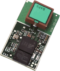
The voltage on the module pad should be maintained below 0.5V
in which case the Ron of the FET is around 20Ω. Provided that this
condition is met, then the current owing through the diode is:
3. The speaker output is capable of driving loads with a minimum
impedance of 16Ω directly.
4. The audio inputs can operate in either line input mode or microphone
mode. The input circuit has a two stage amplier – the rst stage
provides a xed 24dB gain and the second a variable gain of
between -3dB and 18dB. If an input gain of less than 24dB is selected,
then the rst stage is switched out and the module is operating in line
input mode.
Iled =VDD - VFWhere VF is the forward bias voltage of the LED.
R + 20
When operating in microphone mode the
microphone should be biased as follows:
The input impedance on the microphone inputs (in microphone mode) is typically 6kΩ. In order to
maintain the regulation on the MIC_BIAS pin, the current drawn must be in the range 0.2 – 1.23mA.
If the resistor draws less current than this then an additional resistor to ground must be added to
pre-load the microphone output. The audio input is designed for use with inputs of between 1μA
and 10μA at 94dB SPL. If the biasing resistors are set to 1kΩ this implies a microphone with a
sensitivity in the range -40dBV to -60dBV.
When operating in line input mode, the input can be connected directly to the module input pins
in either single or double ended conguration as follows:
AC AC
Single ended Double ended
Note: 1. Reset input is active low. Input is pulled up to VDD_PADS via 22k.
Minimum reset pulse width is 5ms.
2. LED drive pins are open drain outputs and hence the external circuit
to the right should be used.
VDD
Module External Circuit
R
MIC_AP
MIC_AN
Module
External Circuit
MIC_BIAS
15 nH
15 pF
15 nH
15 pF

11
www.lairdtech.com
Laird Technologies
BTM520/521
Bluetooth® Multimedia Plus Module
CONFIGURING
THE BTM520/521
INTRODUCTION
This document describes the protocol used to control and congure the BT-MM+ Bluetooth device.
The AT commands described in the document apply to rmware releases from V14.0.9 onwards.
The protocol is similar to the industry standard Hayes AT protocol used in telephony modems which is
appropriate for cable replacement scenarios, as both types of devices are connection oriented.
Just like telephony modems, Laird Technologies’ devices powers up in an unconnected state and will only
respond via the serial interface. In this state the device will not even respond to Bluetooth Inquiries. Then,
just like controlling a modem, the host can issue AT commands which map to various Bluetooth activities.
The command set is extensive enough to allow a host to make connections which are authenticated and/or
encrypted or not authenticated and/or encrypted or any combination of these. Commands can be saved,
so that on a subsequent power up the device is discoverable or automatically connects.
The device has a serial interface which can be congured for baud rates from 1200 up to 921600 (default
setting is 9600) and an RF communications end point. The latter has a concept of connected and unconnected
modes and the former will have a concept of command and data modes. This leads to the matrix of states
shown below.
RF UNCONNECTED RF CONNECTED
Local Command Mode OK OK
Remote Command Mode ILLEGAL OK
Data Mode ILLEGAL OK
The combinations, ‘Data and RF Unconnected Mode’ and ‘Remote Command and RF Unconnected Mode’ do
not make sense and will be ignored.
Navigation between these states is done using the AT commands which are described in detail in subsequent
sections.
REFERENCES
[1] “AT Command Set”
[2] “BlueLab_v4.0_Release_Note.pdf”
[3] “Audio/Video Distribution Transport Protocol Specication” Rev.V12, 16/04/2007
[4] “Advanced Audio Distribution Prole Specication” Rev. V12, 16/04/2007
[5] “Audio/Video Remote Control Prole” Revision V14r00, 26/06/2008
[6] “Software Release Note Stereo Headset SDK Q3 2007 RC3.1” CS-117522-RNP1, CSR
[7] “Stereo Headset SDK Q3 2007 User Guide” CSR, CS-116451-UGP1, CSR, December2007
[8] “Bluetooth Specication Version 2.1 + EDR [vol3]”, 26 July 2007

12
www.lairdtech.com
Laird Technologies
BTM520/521
Bluetooth® Multimedia Plus Module
CONFIGURING
THE BTM520/521
Glossary of Terms
DESCRIPTION
A2DP : Advanced Audio Distribution Prole
ADC :Analogue to Digital Converter
AGHFP : Audio Gateway Hands-Free Prole
AT : Command prex, ‘Attention’
AVRCP : Audio/Video Remote Control Prole
BISM :Bluetooth Intelligent Serial Module
Codec :Device capable of encoding / decoding an analogue / digital signal
DAC :Digital to Analogue Converter
DSP :Digital Signal Processor
DUN : Dial-Up Network Prole
FTP : File Transfer Prole
GOEP : Generic Object Access Exchange Prole
GPIO :General Purpose Input Output
HFP : Hands Free Prole
HID : Human Interface Device Prole
I/O (IO) : Input/Output
Mic :Microphone
OPP : Object Push Prole
PBAP : Phone Book Access Prole
PWM :Pulse Width Modulation
Sxxx :S-Register No. xxx
SBC : Sub Band Codec
SPP : Serial Port Prole
TBD :To Be Determined
UART :Universal Asynchronous Receiver / Transmitter
PT :PASS THROUGH Command
UI :UNIT INFO Command
SUI :SUBUNIT INFO Command

13
www.lairdtech.com
Laird Technologies
BTM520/521
Bluetooth® Multimedia Plus Module
CONFIGURING
THE BTM520/521
AT Command Set
Assumptions
1. All commands are terminated by the carriage return character 0x0D, which is represented by the string
<cr> in descriptions below this, cannot be changed.
2. All responses from the device have carriage return and linefeed characters preceding
and appending the response. These dual character sequences have the values 0x0D and 0x0A
respectively and shall be represented by the string <cr,lf>.
3. All Bluetooth addresses are represented by a xed 12 digit hexadecimal string, case insensitive.
4. All Bluetooth Device Class codes are represented by a xed 6 digit hexadecimal string, case insensitive.
Commands
The following syntax is employed throughput this document to describe optional or mandatory parameters for
AT commands.
<bd_addr> A 12 character Bluetooth address consisting of ASCII characters ‘0’ to ‘9’, ‘A’ to ‘F’ and ‘a’ to ‘f’.
<devclass> A 6 character Bluetooth device class consisting of ASCII characters ‘0’ to ‘9’, ‘A’ to ‘F’ and ‘a’ to ‘f’.
N A positive integer value.
M An integer value which could be positive or negative, which can be entered as a decimal value or
in hexadecimal if preceded by the ‘$’ character. E.g. the value 1234 can also be entered as $4D2
<string> A string delimited by double quotes. E.g. “Hello World”. The “ character MUST be supplied as delimiters.
<uuid> A 4 character UUID number consisting of ASCII characters ‘0’ to ‘9’, ‘A’ to ‘F’ and ‘a’ to ‘f’.
General AT Commands
1. AT
Used to check the module is available.
Response: <cr,lf>OK<cr,lf>
2. ATA {Answer Call}
Accept an incoming connection, which is indicated by the unsolicited string
<cr,lf>RING 123456789012<cr,lf> every second. 123456789012 is the Bluetooth address of
the connecting device.
Response: <cr,lf>CONNECT 123456789012<cr,lf>
3. ATD<bd_addr>,<uuid> {Make Outgoing Connection}
Make a connection to device with Bluetooth address <bd_addr> and SPP prole <uuid>.
The <uuid> is an optional parameter which species the UUID of the prole server to attach to,
and if not supplied then the default UUID from S Register 101 is used. As this is a device
which utilizes the RFCOMM layer as described in the Bluetooth specication, it necessarily implies
that only proles based on RFCOMM can be accessed.
The timeout is specied by S register 505.
Response: <cr,lf>CONNECT 123456789012<cr,lf>
Or <cr,lf>NO CARRIER<cr,lf>
Due to a known issue in the Bluetooth RFCOMM stack, it is not possible to make more than
65525 outgoing connections in a single power up session. Therefore if that number is exceeded,
then the connection attempt will fail with the following response:-
Response: <cr,lf>CALL LIMIT
Or <cr,lf>NO CARRIER<cr,lf>
In that case, issuing an ATZ to reset the device will reset the count to 0 and more connections
are possible.

14
www.lairdtech.com
Laird Technologies
BTM520/521
Bluetooth® Multimedia Plus Module
CONFIGURING
THE BTM520/521
The following RFCOMM based UUIDs are dened in the Bluetooth Specication:-
4. ATDL {Remake Connection}
Make a connection with the same device and service as that specied in the most recent ATD
command. An error will be returned if the ‘L’ modier is specied AND a Bluetooth address.
If both ‘L’ and ‘R’ modiers are specied then an error will be returned.
Response: <cr,lf>CONNECT 123456789012 AE<cr,lf>
Or <cr,lf>NO CARRIER<cr,lf>
5.ATDR{MakeConnectiontopeerspeciedinAT+BTR}
Make a SPP connection with the device address specied in the most recent AT+BTR command.
The service is as specied in S Register 101. An error will be returned if the ‘R’ modier is specied
AND a Bluetooth address.
If both ‘R’ and ‘L’ modiers are specied then an error will be returned.
Response: <cr,lf>CONNECT 123456789012 AE<cr,lf>
Or <cr,lf>NO CARRIER<cr,lf>
6. ATEn {Enable/Disable Echo}
This command enables or disables the echo of characters to the screen. A valid parameter value
will be written to S Register 506.
All other values of n will generate an error.
Response: <cr,lf>OK<cr,lf>
Or
Response: <cr,lf>ERROR nn<cr,lf>
7. ATH {Drop Connection}
Drop an existing connection or reject an incoming connection indicated by unsolicited RING messages.
Response: <cr,lf>NO CARRIER<cr,lf>
PROFILE NAME UUID
Serial Port 0x1101
LAN Access Using PPP 0x1102
Dialup Networking 0x1103
IrMC Sync 0x1104
OBEX Object Push 0x1105
OBEX File Transfer 0x1106
IrMC Sync Command 0x1107
Headset 0x1108
Cordless Telephony 0x1109
Intercom 0x1110
Fax 0x1111
Audio Gateway 0x1112
WAP 0x1113
WAP_CLIENT 0x1114
E0 Disable echo.
E1 Enable echo.

15
www.lairdtech.com
Laird Technologies
BTM520/521
Bluetooth® Multimedia Plus Module
CONFIGURING
THE BTM520/521
Table 3-1: S-Register List
REGISTER DEFAULT RANGE COMMENT
S0 1 -1..15 Number of RING indication before automatically answering an incoming
connection. A value of 0 disables autoanswer. If -1, then autoanswer on one
RING and do NOT send RING/CONNECT response to the host. This emulates a
serial cable replacement situation
Setting values >= 0, resets S Register 504 to 0 and <0 forces 504 to 1.
If S0 <> 0 and S100 <> 0 then S0 must be < S100. If a value is entered which
violates this rule, then ERROR 29 is sent in response.
If S504 =1 then this register will return -1, regardless of the actual value
stored in non-volatile memory.
S2 0x5E 0x20..0x7E Escape sequence character. It is not ‘+’ by default as a Bluetooth® serial link
can be used to connect to a mobile phone which exposes an AT command
set, which will in turn use ‘+’ as default. So if both used ‘+’ there will be
confusion. 0x5e is the character ‘^’.
S12 100 40..5000 Escape sequence guard time in milliseconds, with a granularity of 20ms. New
values are rounded down to the nearest 20ms multiple
S100 15 0..15 Number of RING indications before an auto disconnection is initiated. A value
of 0 disables this feature.
If S0 <> 0 and S100 <> 0 then S0 must be < S100. If a value is entered which
violates this rule, then ERROR 29 is sent in response.
S101 $1101 0..$ffff UUID of default SPP based prole when not specied explicitly in the ATD
command.
S102 1 1..0x7FF Denes a set of bits masks for enabling prole servers. Values can be ORed.
0x001 is Serial Port Prole
0x080 is A2DP
0x100 is AVRCP
S103 1 1..7 Boot Mode on cold boot.
S126 ? 0 .. 0xFFFF Primer for changing to Multipoint mode
S127 ? 0 .. 0xFFFF 0x100 for At mode
0x200 for Multipoint mode
Other values are reserved
S300 1 0..2 Set A2DP role:
0 is feature not set
1 is A2DP Sink (default)
2 is A2DP Source
S301 1 0..2 Set AVRCP role:
0 is feature disabled
1 is Control (CT) (default)
2 is Target (TG)
8. ATSn=m {Set S Register}
As with modems, the Bluetooth module employs a concept of registers which are used to store
parameters, such as escape sequence character, inquiry delay time etc, as listed in detail below.
The value part ‘m’ can be entered as decimal or hexadecimal. A hexadecimal value is specied via
a ‘$’ leading character. For example $1234 is a hexadecimal number.
When S register values are changed, the changes are not stored in non-volatile memory UNTIL
the AT&W command is used. Note that AT&W does not affect S registers 520 to 525 or 1000
to 1010 as they are updated in non-volatile memory when the command is received.

16
www.lairdtech.com
Laird Technologies
BTM520/521
Bluetooth® Multimedia Plus Module
CONFIGURING
THE BTM520/521 REGISTER DEFAULT RANGE COMMENT
S302 0 0..4 Set AVRCP category:
0 is Feature disabled (default)
1 is Player/Recorder
2 is Monitor/Amplier
3 is Tuner
4 is Menu
S303 0 0..0xFFFFFF Set Company ID:
IEEE Company ID, 24bit hexadecimal,
Required for UNIT INFO Response in AVRCP target mode, default value is 0.
S305 1 0..1 Accept UNIT INFO request:
0 – reject
1 – accept
S306 1 0..1 Accept SUBUNIT INFO request:
0 – reject
1 – accept
S310 1 0..1 Congure PASS THROUGH (PT) Response:
1 = Enable automatic PT-response, response type is read from S311, (default)
0 = Host is required to respond to PT-Indication, see ‘AT+AVR’
S311 1 w
9 r
0..7 (Write) Set automatic PT response:
This value is queried for automatic PT-Response, see Table 3-10.
The written value is mapped internal, that is why the Read-value is different
from the written value. The Read-value is actually sent out as response
S312 1 0..15 A2DP sink supported features (Bitmask) :
Bit 0 = Headphone (default)
Bit 1 = Speaker
Bit 2 = Recorder
Bit 3 = Amplier
S313 1 0..15 A2DP source supported features (Bitmask) :
Bit 0 = Player (default)
Bit 1 = Microphone
Bit 2 = Tuner
Bit 3 = Mixer
S320 2 1..3 Security Level: see [12], Generic Access Prole - Table 5.7
needs subsequent ‘AT&W’ and power cycle to take effect
S321 1 0..4 Set IO capability:
0 – display only
1 – display yes no
2 – keyboard only
3 – no input no output
4 – reject IO-cap requests
S322 0 0..1 Force man-in-the-middle-protection (MITM):
0 – disabled
1 – enabled
S323 0 0..1 Disable legacy (pre-BT2.1) Pairing:
0 – legacy pairing enabled
1 – legacy pairing disabled
S324 90 1..255 Secure Simple Pairing timeout in s
This value must be at least 90 in order to meet the recommendation
of BT2.1 specication

17
www.lairdtech.com
Laird Technologies
BTM520/521
Bluetooth® Multimedia Plus Module
CONFIGURING
THE BTM520/521 REGISTER DEFAULT RANGE COMMENT
S325 1 0..1 Store link key automatically on dedicated bonding outgoing (DBO),
identical with S538
S326 1 0..1 Store link key automatically on general bonding outgoing (GBO)
S327 1 0..1 Store link key automatically on dedicated bonding incoming (DBI)
S328 1 0..1 Store link key automatically on general bonding incoming (GBI)
S329 0 0..1 Enable legacy (BISM2) response format
S330 1 1..15 Congure inquiry response of AT+BTI (Bitmask):
1 – show device address
2 – show class of device
4 – show friendly name
8 – show extended inquiry data
Values can be ORed
S415 0 0..1 Enable Microphone Input Gain, adds extra 24dB to input gain
S416 0 0..1 Enable MicBias
S417 0 0..15 Set MicBiasCurrent
S418 0 0..15 Set MicBiasVoltage
S419 6 0..6 Set sampling rate for Audio Loopback Mode
0 = 8 kHz
1 = 11.025 kHz
2 = 16 kHz
3 = 22.050 kHz
4 = 24 kHz
5 = 32 kHz
6 = 44.1 kHz
S504 0 0..1 Setting to 1 will force S0 to -1 and will suppress messages arising from
connections or pairing. E.g. CONNECT, NO CARRIER, RING, PAIR etc.
Suppressing connection based messaged allows the device to be
congured in cable replacement mode.
S505 10 2..120 Minimum delay before abandoning connection attempt as a master.
Referenced by ATD. In units of seconds. See S Registers 530 and 543 also.
Please note that as disconnection time can vary, this register only guarantees
the minimum delay. Note that for invalid addresses specied in the ATD
command, the “NO CARRIER” response will be immediate. See S register
560 for specifying disconnect max timeout.
S506 1 0..1 Enable/Disable echoes. The ATEn command also affects this.
S507 0 0..2 When set to 0, a connection can be dropped using ^^^ escape sequence only
and the state of DSR line is ignored.
When set to 1 a connection can be dropped using EITHER the ^^^ escape
sequence OR the DSR handshaking line. When set to 2, a connection can
only dropped using a deassertion of DSR. Mode 2 provides for the highest
data transfer rate.
If the status of the DSR line is to be conveyed to the remote device as a low
bandwidth signal then this register MUST be set to 0, otherwise a deassertion
of DSR will be seen as a request to drop the Bluetooth® connection.
This register affects S Register 536 – see details of 536

18
www.lairdtech.com
Laird Technologies
BTM520/521
Bluetooth® Multimedia Plus Module
CONFIGURING
THE BTM520/521 REGISTER DEFAULT RANGE COMMENT
S512 1 0..7 Specify power up state.
When set to 0, AT+BTO is required to open the device for Bluetooth® activity.
When set to 1, it proceeds to a state as if AT+BTO was entered.
When set to 2, it will be discoverable only, similar to issuing AT+BTQ.
When set to 3, it will be connectable but not discoverable e.g. AT+BTG
When set to 4, it will be connectable and discoverable e.g. AT+BTP.
When set to 5, it will be like 2, but all UART RX trafc is discarded in
absence of a connection while DSR is asserted. If DSR is not asserted,
then it behaves exactly as per mode 2.
When set to 6, it will be like 3, but all UART RX trafc is discarded in
absence of a connection while DSR is asserted. If DSR is not asserted,
then it behaves exactly as per mode 3.
When set to 7, it will be like 4, but all UART RX trafc is discarded in
absence of a connection while DSR is asserted. If DSR is not asserted,
then it behaves exactly as per mode 4.
Note that by implication, a change to this can only be seen after a power
cycle AND if AT&W is actioned prior to the power cycle.
If S Reg 554 is non-zero and this register is between 2 and 7 inclusive,
then the value of S554 species the time in seconds that the device will
remain in the specied mode after power up. On timeout, the device will
fall back to the mode specied in S Register 555.
In some rmware builds, S Registers 565 to 569 inclusive are visible, which
allows the start-up mode to depend on the state of RI line (Setting S Reg 565
forces the RI pin to be congured as an input). For this feature to be active,
SReg 565 should be set to 1. In that case, on start-up, if RI is asserted, then
the start-up mode is dened by S Reg 566 and if deasserted then S Reg 567.
S514 10 1..60 Pairing Timeout in seconds. This includes the time a host takes to supply
the PIN number when PIN? messages are indicated.
S515 0x001F00 0.. 0xFFFFFF Default Device Class Code to be used with AT+BTO when it is not explicitly
specied. When queried, the value is always printed as a hexadecimal number.
To change the device class of the module, after AT+BTO, use the command
AT+BTC.
S516 0x000000 0..0x2FFFFFF Default Device Class lter to be used with AT+BTI when it is not explicitly
specied. When queried the value is always printed as a hex number.
The seventh most signicant digit, can be 0,1 or 2, and is used to specify
the type of device class lter.
When 0, it species no ltering.
When 1, it species an AND mask and all 24 bits are relevant
When 2, it species a lter to look for devices with matching major device
class which occupies a 5 bit eld from bits 8 to 12 inclusive (assuming
numbering starts at bit 0). All other 19 bits MUST be set to 0.
S517 20 2..61 Inquiry Length in units of seconds. This parameter is referenced by the
AT+BTI command.
S518 8 0..255 Maximum number of responses from an inquiry request. This parameter is
reference by the AT+BTI command. If this number is set too high, then
AT+BTI will return ERROR 27. For a particular rmware revision, determine
the effective maximum value by trial and error. That is, set to a high value,
send AT+BTI and if ERROR 27 is returned, then retry with a smaller value.
This effective max value will remain unchanged for that particular
rmware build.
S519 500 100..6000 When S507>0, and in a connection, DSR can be used to change from data
to command state by deasserting the DSR line for less than the time specied
in this register. This value is rounded down to the nearest 100ms
S530 1000 100..15000 Reconnect delay when congured as master in pure-cable-replacement
mode. This value is rounded down to the nearest 100ms. See S Register
505 and 543 also.

19
www.lairdtech.com
Laird Technologies
BTM520/521
Bluetooth® Multimedia Plus Module
CONFIGURING
THE BTM520/521 REGISTER DEFAULT RANGE COMMENT
S531 0 0..5 Species the mode on connection establishment.
0 = Normal, that data is exchanged between UART and RF
1 = LOCAL_COMMAND. UART input is parsed by the AT interpreter
and RF data is discarded
2 = REMOTE_COMMAND. RF input is parsed by the AT interpreter and UART
data is discarded. If S Reg 536 is not 1 then this register cannot be set
to 2 and an ERROR will be returned
3 = LOCAL_COMMAND. UART input is parsed by the AT interpreter
and incoming RF data is sent to the host using the RX<string>
asynchronous response.
4 = LOCAL_COMMAND and on the rf side, the gpio is automatically sent
when there is a change in input. See section 9.5 for more details.
5 = DEAMON mode
S532 0 0..7 If non zero then on every connection, a SCO channel (audio) will be initiated.
Bit 0 for HV1, Bit1 for HV2 and Bit2 for HV3. When the connection is lost,
the SCO channel disappears along with it.
S533 1 0..2 If set to 1 then GPIO5 follows RI state, if set to 2 then it follows the state of
DSR and if 0 it is not driven and GPIO5 is available as a user I/O.
This register will not necessarily be effective immediately after changing the
value. It must be saved to non-volatile memory using AT&W and will operate
as expected after an ATZ or a power cycle.
S534 1 0..2 When set to 0, GPIO4 is available as user i/o
If set to 1 then GPIO4 follows DCD state. If set to 2 then GPIO4 behaves
as per setting 1, but in addition, when not in a connection, if the device is
connectable or discoverable, then GPIO4 will blink.
This register will not necessarily be effective immediately after changing the
value. It must be saved to non-volatile store using AT&W and will operate as
expected after an ATZ or a power cycle.
S535 20 0..41 Link Supervision Timeout. If units go out of range, then a NO CARRIER
message will be sent to the host after the time specied here
S536 0 0..1 When set to 1, a remote device can ‘capture’ the AT parser of this unit by it
sending this module an escape “!!!” sequence. The inter character timing is
set via S Register 12.
If S Register 507 is >= 2, then reading this register will always return 0 and
writing 1 will result in ERROR 33.
S538 0 0..1 If 1, then when a successful pairing occurs, it is automatically saved in the
trusted device database – if it has room to store it.
S539 0 0..1 When set to 1, in idle mode (S512=1), UART Rx characters are discarded if
DSR is deasserted.
S541 6 -50..6 This sets the power level in dBm when inquiring or paging. Reading this
register returns the value stored in non-volatile memory.
S542 6 -50..6 As per S541, however reading this register returns the current power level as
set in the base band. The read can be different from S541because the actual
power is set using a lookup table and the base band rounds down to the
nearest value in the table.
S543 0 0..1 If this is set to 1, then incoming pairing attempts will be accepted (if a pin
code has been pre-entered using AT+BTK) while in the wait phase of auto
connect cycle initiated by the AT+BTR command. In addition to accepting
pairing attempts, if the pairing is successful, then the new device is
automatically set as the peer address for automatic connections
(as if an explicit AT+BTR command was entered).
See S Register 505 and 530 also

20
www.lairdtech.com
Laird Technologies
BTM520/521
Bluetooth® Multimedia Plus Module
CONFIGURING
THE BTM520/521 REGISTER DEFAULT RANGE COMMENT
S551 0x3211 0xFFFF This register species in each 4 bit nibble, how the outgoing modem status
bits to the remote peer gets its value. Bluetooth® allows for RTR, RTC, DV
and IC bits to be exchanged over an RFCOMM connection.
Nibble 0..3 species the source for RTC
4..7 species the source for RTR
8..11 species the source for DV (i.e. DCD)
12..15 species the source for IC (i.e. RI)
Each nibble can take the following value:-
0 Always set to 0
1 Always set to 1
2 If DCD (pin 8 on module connector) is output then always 1
If DCD is input then 1 if DCD is asserted otherwise 0
3 If RI (pin 6) is output then always 0
If RI is input then 1 if RI is asserted otherwise 0
4 If DSR (pin 10) is asserted then 1 otherwise 0
In the event that a nibble species DSR as the source of its state, be aware
that if, S Register 507 is anything other than 0, a de-assertion of DSR will
cause the Bluetooth connection to be dropped.
If bits 0..3 and 4..7 are set to 0, then some Bluetooth devices will use
that as a signal to stop sending any data back. For example, Nokia 6310
stops responding.
If this register is changed while in command and connected mode, then
on going back online using the ATO command, a fresh signal will be sent
to the peer to update the bits.
S552 0x0122 0x0FFF This register species in each 4 bit nibble, how the DTR, DCD, RI output
pins are controlled when in a Bluetooth connection
Nibble 0..3 species the source for DTR
4..7 species the source for DCD
8..11 species the source for RI
Each nibble can take the following value:-
0 Do NOT touch the I/O
1 Always deassert
2 Always assert
3 If RTC bit in CONTROL_IND is 1 then assert otherwise deassert
4 If RTR bit in CONTROL_IND is 1 then assert otherwise deassert
5 If DV bit in CONTROL_IND is 1 then assert otherwise deassert
6 If IC bit in CONTROL_IND is 1 then assert otherwise deassert
If this register is changed while in command and connected mode, then
on going back online using the ATO command, the modem output lines
will get refreshed.
S553 0x0201 0x0FFF This register species in each 4 bit nibble, how the DTR,DCD,RI output pins
are controlled when NOT in a Bluetooth connection
Nibble 0..3 species the source for DTR
4..7 species the source for DCD
8..11 species the source for RI
In addition it also refers to S Register 552 to see if the relevant pin is an
input or not to be touched. If the nibble in 552 is 0, then the relevant pin
is an input.
Each nibble can take the following value:-
0 Always deassert
1 Always assert
2 Assert if RING is being sent to the host

21
www.lairdtech.com
Laird Technologies
BTM520/521
Bluetooth® Multimedia Plus Module
CONFIGURING
THE BTM520/521 REGISTER DEFAULT RANGE COMMENT
S554 0 0..900 If S Register 512>=2 and <=7 then this register species a time in seconds
for which the device will stay in the S512 mode after power up or reset. On
timeout, it will abort the discoverable and/or connectable and fall back into
S512=1 mode, when it is deaf and dumb.
Note that if AT+BTR has been used to specify a peer device, then on reverting
to mode 1, it will attempt to make a connection to that peer device.
A power cycle, reset via BREAK or ATZ is required to see the effects of change.
S555 1 1..7 If S Register 554 is nonzero, then after the post reset window expires,
the mode will revert to the mode specied in this register. This allows,
for example, the device to be discoverable and connectable on power up
(mode 4 or 7) and on window timer expiry to revert to connectable only
(mode 3 or 6).
A power cycle, reset via BREAK or ATZ is required to see effects of a change.
In some rmware builds, S Registers 565 to 569 inclusive are visible, which
allows the start-up mode to depend on the state of RI line (Setting S Reg 565
forces the RI pin to be congured as an input). For this feature to be active,
SReg 565 should be set to 1. In that case, on start-up, if RI is asserted, then
the start-up mode is dened by S Reg 568 and if deasserted then S Reg 569.
S558 0 0..1 When 1, the following responses; “RING”, “NO CARRIER” and “CONNECT”
are replaced by “BTIN”, “BTDOWN” and “BTUP” respectively. This will
eliminate ambiguity when the module has a Bluetooth connection to an AT
modem which also gives these responses.
S559 0 0..3 This species a mask.
When Bit 0 is 1, the response word “ERROR“ is replaced by “BTERR” and
“OK” is replaced by “ok”.
When Bit 1 is 1, then error responses do not include the error number and
instead the error number can be retrieved using ATI12.
S560 15 15..120 Disconnect timeout in seconds. This timer species how long to wait for
conrmation from the peer device and/or the underlying stack that the
connection has been successfully torn down. There can be instances where
a conrmation does not arrive and so in this case this timer is used to ‘close
off’ the procedure and put the state machine back into a proper mode for
new operations.
Time is specied with 15 seconds intervals.
S565 0 1 If set to 1, RI (Ring Indicate) line is congured as an input and forces the
start-up mode (SReg512) and post-timeout on Start-up mode (SReg555)
to be dependent on the state of RI. The RI conditional modes are dened
by SRegs 566 to 569 inclusive.
S566 1 7 If S565=1, and RI is asserted then this is the mode the device will start up in.
S567 1 7 If S565=1, and RI is deasserted then this is the mode the device will
start up in.
S568 1 7 If S565=1, and RI is asserted then this is the mode the device will assume
after the post-start-up timeout dened in SReg 554 instead of mode dened
in SReg555
S569 1 7 If S565=1, and RI is deasserted then this is the mode the device will assume
after the post-start-up timeout dened in SReg 554 instead of mode dened
in SReg555
S584 0 0..1 Enable/Disable eSCO
When changing the unit returns ERROR 14 it implies the device is either in
a connection or waiting for a connection and so the new value cannot be
accepted. For the former, drop the connection, then issue the command
AT+BTX and then set the new value and for the latter issue the command
AT+BTX prior to setting the register.
S588 0 0..1 After a disconnection, there will be a cold reset
S589 8 0..F Codec output gain
S590 1 0..3 Codec input gain
S591 0 0..1FF Default GPIO output states when not in a connection. This is used when
virtual digital i/o cable replacement mode is in operation

22
www.lairdtech.com
Laird Technologies
BTM520/521
Bluetooth® Multimedia Plus Module
CONFIGURING
THE BTM520/521 REGISTER DEFAULT RANGE COMMENT
S592 0 0..1 Set this to 1 to reduce the trusted device database to just 1 record
when autosaving of pairing is enabled via S reg 538
S593 0 0..1 Automatically append last 6 digits of local bluetooth address to the
friendlyname which was set via AT+BTN or AT+BTF
S689 0 -450..+215 Set codec output gain in dBr * 10
(applies to sink), default = 0
S690 0 -450..+215 Set codec input gain in dBr * 10
(applies to source), default = 0
S730 0 0..1 Enable Auxiliary DAC
S731 0 0..225 Set Auxiliary DAC Level
9. ATSn? {Read S Register Value}
This will return the current value of register n.
For recognised values of n
Response: <cr,lf>As Appropriate<cr,lf>OK<cr,lf>
For unrecognised values of n
Response: <cr,lf>ERROR nn<cr,lf>
10. ATSn=? {Read S Register – Valid Range}
This will return the valid range of values for register n.
For recognised values of n
Response: <cr,lf>Sn:(nnnn..mmmm)<cr,lf>OK<cr,lf>
For unrecognised values of n
Response: <cr,lf>ERROR nn<cr,lf>
11. ATZ<n> {Hardware Reset and emerge into mode ‘n’}
Forces the device through a hardware reset which means it will eventually come alive in the local
command and unconnected mode. This allows changes to the PS store to take effect. The module
will issue an OK response after the reset is complete and it is ready to receive commands once again.
ATZ and ATZ0 signify reset and emerge into the current mode (see command ATI14). ATZ1 to ATZ4
instructs the module to reset and then emerge into the appropriate boot mode. Note that S Reg 103
species the boot mode from cold.
Response: <cr,lf>OK<cr,lf> and OK is returned after the RESET
12. AT&W {Write S Registers to Non-volatile Memory}
Writes current S Register values to non-volatile memory so that they are retained over a power cycle.
Response: <cr,lf>OK<cr,lf>
Or
Response: <cr,lf>ERROR nn<cr,lf>

23
www.lairdtech.com
Laird Technologies
BTM520/521
Bluetooth® Multimedia Plus Module
CONFIGURING
THE BTM520/521
13. ATIn {Information}
This will return the following information about the Laird Technologies device.
For recognised values of n. All other values of n will generate an error.
Response: <cr,lf>As Appropriate<cr,lf>OK<cr,lf>
Or
Response: <cr,lf>ERROR nn<cr,lf>
I0 The product name/variant.
I1 The CSR rmware build number.
I2 The Laird Technologies rmware build number. For internal use only.
I3 The Laird Technologies rmware revision.
I4 A 12 digit hexadecimal number corresponding to the Bluetooth address of the device.
I5 The manufacturer of this device.
I6 The maximum size of trusted device database.
I7 The manufacturer of the Bluetooth chipset.
I8 The chipset format.
I9 0 if not in a connect state and 1 if in a connect state.
I11 The reason why a “NO CARRIER” resulted in the most recent attempt at making an outgoing connection.
Where the response values are as follows:
0 = No prior connection
1 = Connection timeout
2 = Connection attempt cancelled
3 = Normal disconnection
4 = Peer device has refused connection
5 = Service prole <uuid> requested not available on remote device
6 = Connection has failed
32 = ATH was entered
33 = Incoming connection aborted because too many rings
34 = Unexpected incoming connection
35 = Invalid address
36 = DSR is not asserted
37 = Call limit of 65531 connections has been reached
38 = Pairing in progress
39 = No link key
40 = Invalid link key
255 = Unknown Reason
I12 The last ERROR response number.
I60 Connection status of SPP
0 = not connected
1 = connected
identical with ATI9
I61 Connection status of A2DP
0 = not connected
1 = connected
I62 Connection status of AVRCP
0 = not connected
1 = connected

24
www.lairdtech.com
Laird Technologies
BTM520/521
Bluetooth® Multimedia Plus Module
CONFIGURING
THE BTM520/521
14. ATO {Enter Data Mode} (letter ‘o’)
Return to data mode. Assume that the module is in data mode after OK is received. Responds with
an error if there is no Bluetooth connection.
Response: <cr,lf> CONNECT 123456789012<cr,lf>
Or
Response: <cr,lf>ERROR nn<cr,lf>
15. AT&Fn {Set S Register Defaults}
This command will only work when the device is in local command and unconnected mode.
Depending on the value of ‘n’ it installs S Register values appropriate for various power modes,
ranging from minimum power consumption to maximum.
Legal values of ‘n’ are as per the following table. All other values of n will generate a syntax
error response. If ‘n’ is not specied then a default value of 0 is assumed where the baud rate
is NOT changed.
The new values are NOT updated in non-volatile memory until the AT&W command is sent to
the device.
Response: <cr,lf>OK<cr,lf>
Or
Response: <cr,lf>ERROR nn<cr,lf>
General Bluetooth Control
1.AT+BTAn{ControlAudioChannel}
Once a Bluetooth connection is active, and assuming the peer device is also a Laird Technologies device,
this command is used to start/stop a SCO channel to transfer audio between the two peer devices.
On receipt of the command, the following response immediately follows.
Response: <cr,lf>OK<cr,lf>
The lower layers then go through the process of setting up the SCO channel, and as soon as
a SCO link is established, the following response is asynchronously sent to the host.
Response: <cr,lf>AUDIO ON<cr,lf>
Or if the SCO failed to be established.
Response: <cr,lf>AUDIO FAIL<cr,lf>
On the peer device, the host will asynchronously get ….
Response: <cr,lf>AUDIO ON<cr,lf>
&F0 (Default) Medium power consumption, UART baud rate unchanged.
&F1 Minimum power consumption, UART baud rate set to 9600.
&F2 Minimum power consumption, UART baud rate set to 38400.
&F3 Minimum power consumption, UART baud rate set to 115200.
&F4 Medium power consumption, UART baud rate set to 115200.
&F5 Maximum power consumption, UART baud rate set to 115200.
&F6 Maximum power consumption, UART baud rate set to 115200.
+BTA0 Switch off the channel.
+BTA1 Switch on the channel.

25
www.lairdtech.com
Laird Technologies
BTM520/521
Bluetooth® Multimedia Plus Module
CONFIGURING
THE BTM520/521
2.AT+BTC<devclass>{SetDeviceClassCode}
This command is used to set the device class code which will be sent in subsequent inquiry responses.
It can be read back using the AT+BTC? Command, as described below.
<devclass> is a 6 digit hexadecimal number derived as per section “1.2 The Class of Device/Service
Field” of the Bluetooth specication “Bluetooth Assigned Numbers”.
The 24 bits are made of 4 elds briey described as follows (bit 0 corresponds to the least signicant bit):-
Laird Technologies devices do not map to any predened Major Service Class or Major Device Class
and so the default devclass as shipped is 001F00, which means no Major Service Class and
“Unclassied” Major Device class.
Other examples of device class codes are follows:-
Response: <cr,lf>OK<cr,lf>
Or for an invalid <devclass> value (usually a value which is not 6 hexadecimal characters long).
Response: <cr,lf>ERROR 08<cr,lf>
3.AT+BTC?{ReadDeviceClassCode}
This command is used to read the current device class code.
Response: <cr,lf>123456
<cr,lf>OK<cr,lf>
4.AT+BTD<bd_addr>{RemoveTrustedDevice}
This command is used to remove the specied device from the list of trusted devices in
the non-volatile database. If the device is not in the database then the response will still
be an OK.
Response: <cr,lf>OK<cr,lf>
5.AT+BTD*{RemoveAllTrustedDevices}
This command is used to remove all devices from the list of trusted devices in the non-volatile
database. No conrmation will be asked for. So beware!!!
WARNING: If you make an authenticated connection, the link key gets cached in the underlying
stack. So if you subsequently delete the key using AT+BTD* and immediately request an
authenticated connection to the same device, then the connection will be established. To ensure
this does not happen, either send ATZ after the AT+BTD* OR send AT+BTD<bd_addr> for each
item in the trusted device database.
Response: <cr,lf>OK<cr,lf>
6.AT+BTF=<string>{SetFriendlyName}
This sets the friendly name of this device as seen by other devices
Response: <cr,lf>OK<cr,lf>
Bits 0-1 Format Type. This eld currently only has a value of 00 (i.e. format type 1)
Bits 2-7 These 6 bits dene the Minor Device Class and the value is interpreted differently
based on the Major Device class stored in the next 5 bits.
Bits 8-12 These 5 bits dene the Major Device Class as per Table 1.3 in
“Bluetooth Assigned Numbers”
Bits 13-23 This is an 11 bit eld used as a mask to dene the Major Service Class, as per Table 1.2 in
“Bluetooth Assigned Number”
CODE (HEXADECIMAL) NAME MAJOR SERVICE MAJOR DEVICE MINOR DEVICE
001F00 Unclassied None Unclassied n/a
200404 Headset Audio Audio Headset
26
www.lairdtech.com
Laird Technologies
BTM520/521
Bluetooth® Multimedia Plus Module
CONFIGURING
THE BTM520/521
7.AT+BTF<bd_addr>{GetRemoteFriendlyName}
This command gets the remote friendly name of the peer specied.
Response: <cr,lf><bd_addr>,”Friendly Name”
<cr,lf>OK<cr,lf>
8.AT+BTG<bd_addr>{EnableCautiousPageScanningONLY}
Enable page scanning and wait for a connection from device with Bluetooth address <bd_addr>.
If the specied address is 000000000000 then incoming connections are accepted from any device,
is as per AT+BTP without an address. Inquiry Scans are disabled.
Response: <cr,lf>OK<cr,lf>
9.AT+BTG{EnablePromiscuousPageScanningONLY}
Enable page scanning only and wait for a connection from any device. Inquiry scans are disabled.
Response: <cr,lf>OK<cr,lf>
10.AT+BTI<devclass>{Inquire}
This will make the device perform an inquiry for device class code for delay milliseconds and max
number of unique responses, where delay is specied by S register 517 and max is specied by S
register 518.
The <devclass> is an optional parameter where the value species either a 6 digit device class code
or a 2 digit major device class. If it is not specied, then the value is taken from S register 516.
When <devclass> is 6 hexadecimal characters long, it species an AND mask which is used to lter
inquiry responses. When <devclass> is 2 hexadecimal characters long, it forces the inquiry to lter
responses to devices that match their major device class code to this value – which can only be in
the range 00 to 1F.
Response: <cr,lf>12346789012
<cr,lf>12345678914
<cr,lf>OK<cr,lf>
If the module is waiting for an incoming connection, (entered via AT+BTP, AT+BTG, AT+BTQ),
then it will respond with ERROR 14. To perform the inquiry, send AT+BTX to put the module
back into idle mode.
Response: <cr,lf>ERROR 14<cr,lf>
ERROR RESPONSE
A Bluetooth inquiry process is such that for a single inquiry request a device could respond
many times. To ensure that an address is sent to the host only once for a particular AT+BTI,
an array of addresses is created at the start of each AT+BTI and is lled as responses come in.
This array of addresses is stored in dynamic memory and as such if the memory allocation fails
then the inquiry procedure is aborted and in that case an error response is sent to the host.
To clarify, a single AT+BTI will never return the same Bluetooth address more than once, but as
long as the responding device is active, all AT+BTI commands will always return it.
Response: <cr,lf>ERROR 27<cr,lf>
11.AT+BTIV<devclass>{Inquire}
As per AT+BTI but the response includes the device class code for all inquiry responses. Please refer
to the ‘ERROR RESPONSE’ note in the description for AT+BTI<devclass>.
Response: <cr,lf>12346789012,123456
<cr,lf>12345678914,123456
<cr,lf>OK<cr,lf>
27
www.lairdtech.com
Laird Technologies
BTM520/521
Bluetooth® Multimedia Plus Module
CONFIGURING
THE BTM520/521
12.AT+BTIN<devclass>{Inquire}
As per AT+BTI but the response includes the device class code and friendly name for all inquiry
responses. Please refer to the ‘ERROR RESPONSE’ note in the description for AT+BTI<devclass>.
The friendly name strings are in UTF-8 format as per the Bluetooth specication.
Response: <cr,lf>12346789012,123456,”TDK SYSTEMS AT DONGLE 1”
<cr,lf>12345678914,123456, “TDK SYSTEMS RS232”
<cr,lf>OK<cr,lf>
Note: Many releases of rmware will return the product name as LAIRD, e.g.
Response: <cr,lf>12346789012,123456,”TDK SYSTEMS AT DONGLE 1”
<cr,lf>12345678914,123456, “TDK SYSTEMS RS232”
<cr,lf>OK<cr,lf>
We strongly recommend that any software implementation that uses this command should
check for LAIRD, EZURIO and TDK SYSTEMS to ensure backwards and forwards compatibility.
13.AT+BTK=<string>{SetPasskey}
This command is used to provide a passkey when PIN? 12345678 indications are received
asynchronously. If a pairing is not in progress then the pin is written to non-volatile memory
for future use. Specifying an empty string deletes the key from the non-volatile memory.
The string length must be in the range 0 to 8, otherwise an error will be returned.
Response: <cr,lf>OK<cr,lf>
14.AT+BTM{DeleteIncomingPeerAddress}
This command is used to delete the peer address previously stored using AT+BTR<bd_addr>.
Response: <cr,lf>OK<cr,lf>
15.AT+BTM?{ReadIncomingPeerAddress}
This command is used to display the peer address stored in non-volatile memory, used to put
the module in pure cable replacement mode.
Response: <cr,lf>12346789012
<cr,lf>OK<cr,lf>
If the location is empty the response is as follows.
Response: <cr,lf>00000000000
<cr,lf>OK<cr,lf>
16.AT+BTN=<string>{SetFriendlyNameinNon-volatileMemory}
This sets the default friendly name of this device as seen by other devices. It will be stored
in non-volatile memory. Use AT+BTF to make the name visible to other devices. Use AT+BTN?
To read it back. An empty string (“”) will delete the string from non-volatile memory which will
force the default name to be used.
Response: <cr,lf>OK<cr,lf>
17.AT+BTN?{ReadFriendlyNamefromNon-volatileMemory}
Read the default friendly name from non-volatile memory.
Response: <cr,lf>”My FriendlyName”<cr,lf>
<cr,lf>OK<cr,lf>
28
www.lairdtech.com
Laird Technologies
BTM520/521
Bluetooth® Multimedia Plus Module
CONFIGURING
THE BTM520/521
18 AT+BTP<bd_addr>{EnableCautiousPage/InquiryScanning}
Enable page scanning and wait for a connection from device with Bluetooth address <bd_addr>.
If the specied address is 000000000000 then incoming connections are accepted from any device,
is as per AT+BTP without an address. Inquiry scanning is also enabled.
Response: <cr,lf>OK<cr,lf>
19.AT+BTP{EnablePromiscuousPage/InquiryScanning}
Enable page scanning and wait for a connection from any device. Inquiry scanning is also enabled.
Response: <cr,lf>OK<cr,lf>
20.AT+BTQ{EnableInquiryScansONLY}
When inquiry scan is enabled, it implies that this device will respond to inquiries from other devices.
Use AT+BTX to disable inquiries.
Response: <cr,lf>OK<cr,lf>
21.AT+BTR<bd_addr>{SetOutgoingPeerAddress}
This command is used to store a peer address for outbound connections in non-volatile memory.
A value of 000000000000 has the special meaning of invalid peer address.
This command is used to set up a module in pure cable replacement mode.
If S register 512 = 1 and the peer address is NOT 000000000000, then it will periodically (time
specied via S register 505) attempt to connect to the peer address specied. In this circumstance
all commands from the host are buffered in the receive buffer, until a Bluetooth connection is
established with the peer device and it then sends the buffer across. This means that if the peer
device is not in the vicinity and will never be there, the device effectively becomes useless, as in
this circumstance a host would want to get attention of the AT parser to send it new commands
– probably one to delete the peer device.
In this circumstance, a recovery is possible by one of two methods. The rst method assumes that
the DTR from the host is connected to the DSR line of the module and the second method assumes
that this connection is absent. In the rst method it is enough to deassert the DTR line from the host
and that will abort the autoconnect cycle. The second method is initiated by resetting the device
and then ensuring that the text string “AT+BT&BISM&<cr>” is sent (where <cr> is the carriage
return character). There is special code which looks out for this magic command and terminates
the autoconnect cycle if it sees it and conrms to the host of that fact by sending an “OK” response.
Response: <cr,lf>OK<cr,lf>
22.AT+BTR{DeleteOutgoingPeerAddress}
This command is used to delete the peer address previously stored using AT+BTR<bd_addr>.
Response: <cr,lf>OK<cr,lf>
23.AT+BTR?{ReadOutgoingPeerAddress}
This command is used to display the peer address stored in non-volatile memory, used to put the
device in pure cable replacement mode.
Response: <cr,lf>12346789012
<cr,lf>OK<cr,lf>
If the location is empty the response is as follows.
Response: <cr,lf>00000000000
<cr,lf>OK<cr,lf>
29
www.lairdtech.com
Laird Technologies
BTM520/521
Bluetooth® Multimedia Plus Module
CONFIGURING
THE BTM520/521
24.AT+BTT{AddTrustedDevice}
This command is used to store the cached link key in the non-volatile database. If the database is full
it will respond with an ERROR. If the device is already in the database, then the key is replaced.
If the link key cache is empty, that is, a pairing has not been performed since the device was powered,
then the response will be an ERROR.
Response: <cr,lf>OK<cr,lf>
Or
Response: <cr,lf>ERROR<cr,lf>
25.AT+BTT?{ListTrustedDevice}
This command is used to list the contents of the trusted device database. The link key is NOT
displayed so the response is as shown below. If the list is empty then just the OK response is sent
otherwise an OK is used to terminate the list. Use the command ATI6 to read the maximum size of
the trusted device database.
Response: <cr,lf>12346789012
<cr,lf>12345678913
<cr,lf>12345678914
<cr,lf>OK<cr,lf>
26.AT+BTW<bd_addr>{InitiatePairing}
This initiates pairing with a device whose Bluetooth address is <bd_addr>. An OK response is sent
and when the PIN is required, asynchronous indications will be sent to the host in the form PIN?
<bd_addr> where the address conrms the device with which the pairing is to be performed.
To supply a PIN, use the AT+BTK command.
For a successful pairing, the link key is stored in a volatile cache which is overwritten every time a
new pairing is initiated using this command. The link key can be stored in a non-volatile database
within the device. The list of trusted devices is managed using commands AT+BTT?, AT+BTT and
AT+BTD. The AT+BTT? command produces a list of trusted Bluetooth addresses (link key is NEVER
displayed) and AT+BTT is used to store the cached link key. The command AT+BTD123456789012
is used to remove the specied device from the database.
The “OK” response is sent immediately on receipt of the AT+BTW command. On pairing completion,
an unsolicited message will be sent to the host which will be in the form PAIR n <bd_addr>.
See section 3.7 for more details.
If AT+BTI or AT+BTP or AT+BTG or AT+BTQ or ATD is issued between the AT+BTW command
and the subsequence PAIR asynchronous response, then an ERROR response will be sent to
those commands as the device is not in a mode from where such commands can be actioned.
Response: <cr,lf>OK<cr,lf>
27.AT+BTW?{ListCachedTrustedDevice}
This command is used to list the cached trusted device.
Response: <cr,lf>12346789012
<cr,lf>OK<cr,lf>
If the cache is empty the response is as follows.
Response: <cr,lf>OK<cr,lf>
28.AT+BTX{DisablePage/InquiryScanning}
Disable page/inquiry scanning. This means it will not accept incoming connections or inquiry requests.
In fact this negates the effect of AT+BTQ, AT+BTG and AT+BTP commands.
Response: <cr,lf>OK<cr,lf>

30
www.lairdtech.com
Laird Technologies
BTM520/521
Bluetooth® Multimedia Plus Module
CONFIGURING
THE BTM520/521
Hardware Unit Control
This section covers S-Registers and AT-Commands that are related to hardware units within the module.
1. Audio Loopback Mode
For testing purposes, an audio loopback mode will be introduced. The stereo audio input signal
is fed through the Kalimba DSP with running SBC codec, and is directed back to the audio stereo
output. Audio Loopback Mode is controlled with the new AT Command “AT+BTL”.
2.CodecGain
On BC05-MM, analogue input and output gains can be set to one of 23 steps called “Gain Level”.
To each gain level, an overall gain (dBr) is assigned, according to Table 3 3: Gain Table. Gain values
can be specied either as gain level or as overall gain by separate S Registers. Please note that a
pair of such S-Registers always updates the other corresponding S-Register (e.g. S589 – S689
and S590 – S690).
For S689 and S690 the overall gain (dBr) must be entered multiplied by 10. If the input value
doesn’t match a gain table entry, the nearest possible value is set. The actually set value can be
checked by reading back S689/S690. The value of S689/S690 is printed out multiplied by 10 in
order to avoid non integer numbers.
The new command class “AT+G…” is introduced in Bism3 which enables incremental
and decremental gain settings. The increment/decrement command corresponds to one row
up/down in the gain table (Table 3 3). The Gain level registers S589/S689 and S590/S690 are
not affected by increment/decrement commands. Instead, the current gain level is cached
and can be retrieved by “AT+G(I|O)?”. There are 2 further commands to restore the cached
gain level from S589/S590 (“AT+G(I|O)R”) and to save the currently cached gain level
to S589/S590 (“AT+G(I|O)S”).
Table 3-2: Audio Loopback AT-Commands and S-Registers
TASK AT-COMMAND / SREGISTER COMMENT
Set audio loopback mode AT+BTL<Mode> Mode:
0 = off
1 = on, via PCM
2 = on, via SBC encoder/decoder
Set sampling rate for Audio
Loopback Mode
S419 [0..6], default=6 0 = 8 kHz
1 = 11.025 kHz
2 = 16 kHz
3 = 22.050 kHz
4 = 24 kHz
5 = 32 kHz
6 = 44.1 kHz

31
www.lairdtech.com
Laird Technologies
BTM520/521
Bluetooth® Multimedia Plus Module
CONFIGURING
THE BTM520/521
Table3-3:GainTable
OUTPUT GAIN LEVEL OR
INPUT GAIN LEVEL
S589 OR S590
OVERALL GAIN (DBR)
S689 OR S690
22 +21.5
21 +18.0
20 +15.5
19 +12.0
18 +9.5
17 +6.0
16 +3.5
15 0
14 -3.0
13 -6.0
12 -9.0
11 -12.0
10 -15.0
9 -18.0
8 -21.0
7 -23.5
6 -27.0
5 -29.5
4 -33.0
3 -35.5
2 -39.0
1 -41.5
0 -45.0
TASK AT-COMMAND / SREGISTER COMMENT
Set output gain level S589 [0..22], default=15 See Gain Table; S689 is affected, too
Set output overall gain (dBr) S689 [-450..+215], default=0 See GainTable; value must be entered (and is
returned) multiplied by 10; S589 is affected, too
Set input gain level S590 [0..22], default=15 See Gain Table; S690 is affected, too
Set input overall gain (dBr) S690 [-450..+215], default=0 See GainTable; value must be entered (and is
returned) multiplied by 10; S590 is affected, too
Increment current output
gain level
AT+GOU Error 57 may appear if maximum gain
level reached
Decrement current output
gain level
AT+GOD Error 58 may appear if minimum gain
level reached
Query current output gain level AT+GO?
Restore current output gain
level from S589
AT+GOR
Save current output gain
level to S589
AT+GOS
Increment current input
gain level
AT+GIU Error 57 may appear if maximum gain
level reached
Decrement current input
gain level
AT+GID Error 58 may appear if minimum gain
level reached
Query current input gain level AT+GI?
Restore current input gain
level from S590
AT+GIR
Save current input gain
level to S590
AT+GIS
Table3-4:GainSettingsATCommandsandS-Registers

32
www.lairdtech.com
Laird Technologies
BTM520/521
Bluetooth® Multimedia Plus Module
CONFIGURING
THE BTM520/521
3.MicInputGain
A microphone preamplier which adds extra 20dB to input gain, is controlled by S-Register 415.
4.MicBias
Mic Bias will be enabled with S-Register 416.
Mic Bias Current is controlled by S-Register 417.
Mic Bias Voltage is controlled by S-Register 418.
5. Auxiliary DAC
The auxiliary DAC is enabled with S-Register 730.
The DAC output level is set by S-Register 731.
6. LED
The BT-MM+ module provides two dedicated output pins for LEDs (LED_EXT0, LED_EXT1).
Following modes are supported: LED_OFF, LED_ON, LED_PWM and LED_PULSE.
In LED_PWM mode, the parameters “Duty Cycle” an “PWM Period” can be specied via S-Registers.
This enables either a to dim the brightness of an LED (PWM Period=0) or to specify blinking with
dened on-time in a dened period (PWM Period > blinking visible for the eye)
In LED_PULSE mode, the brightness of an LED is modulated. Modulation speed is dened by
parameter “Pulse Rate” and maximum brightness is dened by parameter “Duty Cycle”.
Bluetooth Proles
This section covers S-Registers and AT-Commands that are related to the supported Bluetooth Proles on the
BT-MM+ module.
1.ProleServerActivation
In order to advertise available services to potential client devices, S-Register 102 is used.
Supported proles can be activated by setting the appropriate Flag in S-Register 102 (see Table 3 1).
After S-Register 102 has been written, all S-Registers must be saved to non-volatile memory (“AT&W”)
and subsequently a reset has to be carried out (“ATZ”).
2.A2DP
The “Advanced Audio Distribution Prole” is used to transmit high quality audio streams between
two Bluetooth devices. An A2DP role must be assigned to a BT-MM+ module, either source or sink.
After this has been done, the appropriate service can be advertised. An attempt to advertise
A2DP-service without prior set up of a role will result in a (new) response error code 46.
An incoming A2DP connection request is accepted automatically if a valid link key for the paging
device exists. If no link key is available, Secure Simple Pairing (SSP, BT2.1) or legacy pairing (BT2.0
or earlier) is carried out, depending on the Bluetooth Version of the paging device.
After an A2DP connection has been established, the module remains in AT Command mode.
S Register 531 is ignored for A2DP connections.
Table 3-5: LED S-Registers
TASK AT-COMMAND / SREGISTER COMMENT
Set LED_EXT0 mode S335 [0..3], default=0 Mode:
0 = LED_OFF
1 = LED_ON
2 = LED_PWM
3 = LED_PULSE
Set LED_EXT1 mode S340 [0..3], default=0
Set LED_EXT0 Duty Cycle S336 [0..4095], default = 2048 referenced if LED mode = LED_PWM
or LED_PULSE
Set LED_EXT1 Duty Cycle S341 [0..4095], default = 2048
Set LED_EXT0 PWM Period S337 [0..15], default = 0 referenced if LED mode = LED_PWM
Set LED_EXT1 PWM Period S342 [0..15], default = 0
Set LED_EXT0 Pulse Rate S338 [0..15], default = 0 referenced if LED mode = LED_PULSE
Set LED_EXT1 Pulse Rate S343 [0..15], default = 0

33
www.lairdtech.com
Laird Technologies
BTM520/521
Bluetooth® Multimedia Plus Module
CONFIGURING
THE BTM520/521
Table3-6:A2DP-S-RegistersandAT-Commands
TASK AT-COMMAND / SREGISTER COMMENT
Set A2DP role S300 [0..2] 0 = feature not set
1 = A2DP Sink (default)
2 = A2DP Source
Advertise service S102 128 = A2DP, Error 46 if A2DP role has not
been set (see S300)
Initiate outgoing
A2DP connection
AT+APD<bd_addr> Response if accepted:
“CONNECT 0123456789012,110D”
Response if rejected:
“NO CARRIER 110D”
close only A2DP connection “AT+APH” or “ATH110D” Response:
“NO CARRIER 110D” if connection has
existed and S329=0
“NO CARRIER” if connection has not
existed and S329=0
close all connections ATH* Response:
“NO CARRIER <proleUUID>” for each
prole that was previously connected
(see section 3.7.2)
Set gain level S589 [0..22], default = 15 Set codec output gain level (applies to sink)
S590 [0..22], default = 15 Set codec input gain level (applies to source)
Set overall gain (dBr * 10) S689 [-450..215] Set codec output gain in dBr * 10
(applies to sink), default = 0
S690 [-450..215] Set codec input gain in dBr * 10
(applies to source), default = 0
Set A2DP sink supported
features bit mask
S312 [0..15] Bitmask - sink supported features:
Bit 0 = Headphone (default)
Bit 1 = Speaker
Bit 2 = Recorder
Bit 3 = Amplier
Set A2DP source supported
features bit mask
S313 [0..15] Bitmask - source supported features:
Bit 0 = Player (default)
Bit 1 = Microphone
Bit 2 = Tuner
Bit 3 = Mixer
3.AVRCP
The “Audio/Video Remote Control Prole” is used to remotely control audio or video streaming
devices. A device must be dened as either control or target. Furthermore, one of four categories
(Player/Recorder, Monitor/Amplier, Tuner, Menu) has to be assigned to a device.
The AVRCP specication [5] adopts the AV/C Digital Interface Command Set (AV/C command set,
dened by the 1394 Trade Association) device model and control message format. In this device
model a remote control target consists of one or more subunits. At least the subunit ”PANEL”
must exist. Remote control commands are passed to a subunit with the “PASS THROUGH”
command. A BT-MM+ Module, congured as target will support one PANEL subunit.
3.1 AVRCP-Control(CT)
This section describes AT Commands and S registers used when BT-MM+ is congured as
an AVRCP Controller (S301=1).
34
www.lairdtech.com
Laird Technologies
BTM520/521
Bluetooth® Multimedia Plus Module
CONFIGURING
THE BTM520/521
3.1.1 InitiateAVRCPcontrolconnection
AT+AVD<bd_addrhex>
Initiate AVRCP control connection to Bluetooth address <bd_addrhex>. The module must
be congured as AVRCP Control by S register 301 = 1. Furthermore, a category be selected
in S register 302.
Response: <cr,lf>CONNECT 123456789012,110E<cr,lf>
Or: <cr,lf>NO CARRIER 110E<cr,lf>
Or: <cr,lf>ERROR 47<cr,lf>
Or: <cr,lf>ERROR 48<cr,lf>
After an AVRCP connection has been established, the module remains in AT
command mode. S Register 531 is ignored for AVRCP connections.
3.1.2 ReleaseAVRCPcontrolconnection
AT+AVH
Release AVRCP control connection.
Response: <cr,lf >NO CARRIER 110E<cr,lf>
3.1.3 SendUNITINFORequest
AT+AVU
Send a Unit Info request to a connected AVRCP target.
Response immediately: <cr,lf>OK<cr,lf>
On command completion:
<cr,lf>AVUR <n> <unit_idhex> <unit_typehex> <company_idhex><cr,lf>
n = statusdec : 0 – success
1 – fail
4 – timeout
For unit_type see Table 3 9: AV/C Unit/Subunit Types.
3.1.4 SendSUBUNITINFORequest(incomplete)
AT+AVS<pagedec>
Send a Subunit Info request to a connected AVRCP target.
Response: <cr,lf>OK<cr,lf> (immediately)
And: <cr,lf>AVSR <pagedec> <pagedatahex> <cr,lf> (after command completion)
<pagedec> : requested page [0..31]
<pagedatahex> : 1st word of requested page
35
www.lairdtech.com
Laird Technologies
BTM520/521
Bluetooth® Multimedia Plus Module
CONFIGURING
THE BTM520/521
3.1.5 Send remote control command
AT+AVC<operation_idhex>,<button_state>
Send a remote control command to a connected AVRCP target. Internally, a PASS
THROUGH command is created and sent to the PANEL subunit of the AVRCP target.
<operation_idhex> is the value for the actual remote control command. Valid values are
specied in Table 3 8. Some Operation IDs can be replaced by mnemonics, see Table 3 8.
<button_state> represents “Button pushed” (=0) or “Button released” (=1)
If <button_state> is not specied, two PASS THROUGH commands, each with
button_state=0 and button_state=1 will be created and sent consecutively.
The “OK” response is sent immediately on receipt of AT+AVC command. On command
completion, an unsolicited message will be sent to the host in the form “AVPTC n
<bd_addr> <button_state>”. AVPTC means “AVrcp Pass Through Conrmation”.
Parameter n indicates the command status:
‘n’=0: successful, command conrmation received from target
‘n’=1: timeout, target has not sent conrmation within the specied maximum time
‘n’=2: all other unsuccessful outcomes
Parameters:
<operation_idhex> (mandatory): see Table 3 8
<button_state> (optional) : ‘0’ - Button pushed
‘1’ - Button released
Response: <cr,lf>OK<cr,lf> (immediately)
And: <cr,lf>AVPTC n <operation_idhex> <button_state><cr,lf>
(after command completion)
If status n indicates an unsuccessful outcome,<operation_idhex> and <button_state>
are omitted.
3.2 AVRCP–Target(TG)
This section describes AT Commands and S registers when BT-MM+ is congured as an AVRCP
Target (S301=2). In this mode, BT-MM+ supports one subunit PANEL (see [5]).
3.2.1 IncomingAVRCPConnectionRequest
An incoming AVRCP connection request is accepted automatically if a valid link key for
the paging device exists. If no link key is available, Secure Simple Pairing (SSP, BT2.1)
or legacy pairing (BT2.0 or earlier) is carried out, depending on the Bluetooth Version
of the paging device.
After an AVRCP connection has been established, the module remains in AT command
mode. S Register 531 is ignored for AVRCP connections.
3.2.2 UNIT INFO Response
It is mandatory to respond to a UNIT INFO command if congured as AVRCP target.
Required response parameters are IEEE Company ID and a Unit Type.
The IEEE Company ID is a 24 bit integer which can be set via new S register 303.
In the current revision of BT-MM+ rmware, subunit “Panel” (=0x09) will be returned
always. Values of unit/subunit types are outlined in Table 3 9.
3.2.3 SUBUNITINFOResponse
It is mandatory to respond to a SUBUNIT INFO command if congured as AVRCP target.
Required response parameters are Subunit type and MaxSubUnitId.
Subunit type will always be returned as 0x09 (Panel).
MaxSubUnitId will always be returned as 0x00 (only one subunit exists, which is panel)

36
www.lairdtech.com
Laird Technologies
BTM520/521
Bluetooth® Multimedia Plus Module
CONFIGURING
THE BTM520/521
3.2.4 PASSTHROUGHIndication
An incoming PASS THROUGH command will be indicated by an unsolicited message
AVPTI <subunit_idhex> <operation_idhex> <button_state>
For subunit_idhex see Table 3 9. For operation_idhex see Table 3 8.
<button_state>: ‘0’ is Button pushed
‘1’ is Button released
3.2.5 PASSTHROUGHResponse
AT+AVR<avrc_response_typehex>
If S register 310 = 0, a Pass Through (PT) response is required from the host.
The response is sent with:
AT+AVR<avrc_response_typedec>
Parameter:
<avrc_response_typedec>: see Table 3 10, write-value.
If S register 310 == 1, a Pass Through response is sent automatically with an
<avrc_response_type> congured by S register 311. In this case, the host is
not required to respond.
Table3-7:AVRCP-S-RegistersandAT-Commands
TASK AT-COMMAND / SREGISTER COMMENT
Set AVRCP role S301 [0..2] 0 = disabled
1 = Control “CT” (default)
2 = Target “TG”
Set AVRCP category S302 [0..4] 0 = Feature disabled (default)
1 = Player/Recorder
2 = Monitor/Amplier
3 = Tuner
4 = Menu
Set Company Id S303 [0..0xFFFFFF] IEEE Company ID, 24bit hexadecimal,Required for UNIT
INFO Response in AVRCP target mode, default value is 0.
Enable Unit Info Response S305 [0..1] default = 1
Enable Subunit Info Response S306 [0..1] default = 1
Congure PASS
THROUGH (PT) Response
S310 [0..1] 1 = Enable automatic PT-response, response type is read
from S311, (default)
0 = Host is required to respond to PT-Indication, see
‘AT+PTR’
Set automatic response
type
S311 [0.. 7] This value is queried for automatic PT-Response, see Table 3-10
Default value is “accepted” 1w/ 9r
Advertise service S102 256 = AVRCP, Error 47 if AVRCP role has not been set (see S301);
Error 48 if S301== 2 and Category has not been set (see S302)
Initiate outgoing AVRCP
control connection
AT+AVD<bd_addr> Response if accepted:
“CONNECT 0123456789012,110E”
Response if rejected:
“NO CARRIER 110E”
Close only AVRCP con-
nection
“AT+AVH“ or “ATH110E” Response:
“NO CARRIER 110E” if connection has existed and S329=0
“NO CARRIER” if connection has not existed and S329=0
Close all connections ATH* Response:
“NO CARRIER <proleUUID>” for each prole that was
previously connected (see Miscellaneous section 2)
Send a Unit Info request AT+AVU
Send a Subunit Info
request
AT+AVS (incomplete!)
Send remote control com-
mand
AT+AVC<operation_
idhex>,<state>
<operation_id>: see Table 3 8, mnemonics possible instead
of hexval
<state> (optional): ‘0’ Button pushed
‘1’ Button released
Response on command completion:
“AVPTC n <operation_idhex> <state>”
Respond to incoming Pass
Through command
AT+AVR<avrc_response_typehex> <avrc_response_typehex>: see Table 3 10
If S 310 == 1, response from host is not required.

37
www.lairdtech.com
Laird Technologies
BTM520/521
Bluetooth® Multimedia Plus Module
CONFIGURING
THE BTM520/521
Table3-8:AVRCP-OperationIDandMnemonicforRemoteControlCommands
COMMAND OPERATION ID MNEMONIC
Select 0x00
Up 0x01
Down 0x02
Left 0x03
Right 0x04
Right up 0x05
Right down 0x06
Left up 0x07
Left down 0x08
Root menu 0x09
Setup menu 0x0A
Contents menu 0x0B
Favorite menu 0x0C
Exit 0x0D
0 0x20
1 0x21
2 0x22
3 0x23
4 0x24
5 0x25
6 0x26
7 0x27
8 0x28
9 0x29
Dot 0x2A
Enter 0x2B
Clear 0x2C
Channel up 0x30
Channel down 0x31
Sound select 0x32
Input select 0x33
Display information 0x34
Help 0x35
Page up 0x36
Page down 0x37
Power 0x40
Volume up 0x41
Volume down 0x42
Mute 0x43
Play 0x44 PLAY
Stop 0x45 STOP
Pause 0x46 PAUSE
Record 0x47
Rewind 0x48 REWIND
Fast forward 0x49 FFORWARD
Eject 0x4A
Forward 0x4B FORWARD
Backward 0x4C BACKWARD
Angle 0x50
Sub picture 0x51
F1 0x71
F2 0x72
F3 0x73
F4 0x74
F5 0x75
Vendor unique 0x7e

38
www.lairdtech.com
Laird Technologies
BTM520/521
Bluetooth® Multimedia Plus Module
CONFIGURING
THE BTM520/521
Table 3-9: AV/C Unit/Subunit Types
UNIT / SUBUNIT TYPE VALUE
Monitor 0x00
Audio 0x01
Printer 0x02
Disc 0x03
Tape recorder player 0x04
Tuner 0x05
CA 0x06
Camera 0x07
Reserved 0x08
Panel 0x09
Bulletin board 0x0A
Camera storage 0x0B
Vendor unique 0x1C
Reserved for all 0x1D
Extended 0x1E
Unit 0x1F
Table 3-10: AVRC Response Types
AVRC RESPONSE TYPE READ-VALUE (S311,
SENT IN RESPONSE)
WRITE-VALUE (S311)
Not implemented 80
Accepted 9 1
Rejected 10 2
In transition 11 3
Stable 12 4
Changed 13 5
Interim 15 6
Bad prole 16 7
Table3-11:AVRCPUnsolicitedMessages
MESSAGE COMMENT
RING 0123456789012 110E Indication of AVRCP control connection request
CONNECT 0123456789012 AE 110E AVRCP control connection established‘0123456789012’ – bd_addr
of peer device ‘A’ - authenticated
‘E’ – encrypted
‘110E’ – UUID indicating AVRCP
NO CARRIER 110E AVRCP connection rejected or closed
NO CARRIER All Connections closed
AVUR <unit_typehex> <company_idhex> AV Unit Info Response, sent in response to AT+AVU
(UNIT INFO Request),
<unit_type>: see Table 3 9
<company_id>: IEEE Company ID
AVSR AV Subunit Info Response, sent in response to AT+AVS (SUBUNIT INFO
Request), incomplete
AVPTI <subunit_idhex> <operation_idhex> <state> Indication of incoming Pass Through command
<subunit_idhex>: subunit id
<operation_idhex>: see Table 3 8
<state>: ‘0’ – Button pushed
‘1’ – Button released
AVPTC n <operation_idhex> <state> Conrmation of AT+AVC (Control Command Request)
n: ‘0’ – successful
‘1’ – timeout
‘2’ – not successful, other than timeout
RING 0123456789012 110E Indication of AVRCP control connection request
39
www.lairdtech.com
Laird Technologies
BTM520/521
Bluetooth® Multimedia Plus Module
CONFIGURING
THE BTM520/521
SECURE SIMPLE PAIRING (SSP)
Secure Simple Pairing is supported on the BT-MM+ module. A set of S Registers provides conguration capabili-
ties for SPP:
• Security Level – S320
• IO-Capability – S321
• Force man-in-the-middle-protection (MITM) – S322
• Disable legacy pairing – S323
For details see Table 3 1.
LINK KEY MANAGEMENT
On BT-MM+ link keys are managed by the AT rmware.
1.DedicatedBonding
In BT2.1 specication, “dedicated bonding” is dened as the exchange of link keys between two
devices without the intention of establishing a connection immediately.
Dedicated bonding is initiated by “AT+BTW<BdAddr>” (initiation of pairing).
2.GeneralBonding
In BT2.1 specication, “general bonding” is dened as the exchange of link keys between two
devices with the intention of establishing a connection immediately. This is the case if a device wants
to connection to another device without existing link key. Hence, pairing (authentication and exchange
of link keys) is initiated automatically prior to the connection.
General bonding is initiated by “ATD<BdAddr>”, “AT+APD<BdAddr>”, “AT+AVD<BdAddr>” if
there are no link keys for the peer device existing.
3.LegacyIssues(BT2.0)
There are some special cases if a legacy device (BT2.0 or earlier, e.g.BISM2) requests a connection
to a BT-MM+ (BT2.1) module.
General bonding does not work if initiated by the legacy device. Instead, the legacy device must
initiate dedicated bonding rst (for example on BISM2 the command “AT+BTW<BdAddr>” would
be used). After successful pairing, the connection can be initiated by the legacy device (for example
on BISM2 the “ATD<BdAddr>” command would be used).

40
www.lairdtech.com
Laird Technologies
BTM520/521
Bluetooth® Multimedia Plus Module
CONFIGURING
THE BTM520/521
MISCELLANEOUS
1.ProleConnectionStatus
The connection status of a prole can be queried by an ATI-Command. This might be helpful in order
to decide whether to disconnect all connected proles (via ATH*) or a certain one. For details please
see Table 3-12.
2.DisconnectingProles
A connection to a prole can be released by “ATH<Prole-UUID>” or by using the prole specic
disconnect command.
The response on a disconnect command is “NO CARRIER <proleUUID>”. If no connection existed
then the proleUUID is omitted.
If all connections are to be released, ATH* may be used. Please see Table 3-13.
3.ProductionInfoString
A string with production information can be retrieved by “ATI200”.
Table3-13:ProleReleaseCommands
TASK AT-COMMAND COMMENT
Disconnect A2DP ATH110D orAT+APH If A2DP connection released:
response = “NO CARRIER 110D”;
If no A2DP connection has existed:
response = “NO CARRIER”
Disconnect AVRCP ATH110E or AT+AVH If AVRCP connection released:
response = “NO CARRIER 110D”;
If no AVRCP connection has existed:
response = “NO CARRIER”
Disconnect all proles ATH* Response = “NO CARRIER
<ProleUUID>” for each previously
connected prole
Table3-12:ProleConnectionStatus
TASK AT-COMMAND COMMENT
Get connection status of SPP ATI60 0 = not connected
1 = connected
identical with ATI9
Get connection status of A2DP ATI61 0 = not connected
1 = connected
Get connection status of AVRCP ATI62 0 = not connected
1 = connected

41
www.lairdtech.com
Laird Technologies
BTM520/521
Bluetooth® Multimedia Plus Module
CONFIGURING
THE BTM520/521
APPENDIx
BT-MM+ Unsolicited Messages
BT-MM+ Error Responses
MESSAGE COMMENT
CONNECT 0123456789012,110D A2DP control connection established ‘0123456789012’ – bd_
addr of peer device ‘110D’ – Prole UUID indicating A2DP
NO CARRIER 110D A2DP connection rejected or closed (if S329==0)
CONNECT 0123456789012,110E AVRCP control connection established ‘0123456789012’ – bd_
addr of peer device ‘110E’ – Prole UUID indicating AVRCP
NO CARRIER 110E AVRCP connection rejected or closed (if S329==0)
AVUR n <unit_idhex> <unit_typehex> <company_idhex>AV Unit Info Response, sent in response to AT+AVU (UNIT INFO
Request),
<unit_idhex>: unit id
<unit_typehex>: see Table 3 9
<company_id>: IEEE Company ID
AVSR <pagedec> <pagedatahex> AV Subunit Info Response, sent in response to
AT+AVS (SUBUNIT INFO Request),
Page data: 1st word of requested page, incomplete
AVPTI <operation_idhex> <button_state> <subunit_idhex>
<subunit_typehex>
Indication of incoming Pass Through command
<operation_idhex>: see Table 3 8
<button_state>: ‘0’ – pushed
‘1’ – released
<subunit_idhex>: subunit id
<subunit_typehex>: subunit type, see Table 3 9
AVPTC n <operation_idhex> <state> Conrmation of AT+AVC (Control Command Request)
n: ‘0’ – successful
‘1’ – timeout
‘2’ – not successful, other than timeout
PAIR ? <BdAddr> Incoming pairing request from device with BdAddr
PAIR 0 <BdAddr> Succesfully paired with device with BdAddr
PAIR 1 <BdAddr> Pairing error
PASSKEY ? <BdAddr> Incoming passkey request (respond with at+btb012345)
PASSKEY N <BdAddr> 012345 Passkey notication (if MITM protection is enabled)
ERROR DESCRIPTION
01 Register not recognised
02 Value for register is out of range
03 Incoming call NOT pending
04 No call to connect to. This error code has meaning for ATO only
05 Syntax Error
06 Empty String
06 Device Class could not be stored
08 Invalid Device Class Code
09 Invalid Bluetooth Address
10 Could not set Service or Friendly name
11 PS Store Write
12 PS Store Read
13 Not Idle
14 Incorrect Mode
15 Already Scanning
16 Pairing is already in progress
17 Not USED

42
www.lairdtech.com
Laird Technologies
BTM520/521
Bluetooth® Multimedia Plus Module
CONFIGURING
THE BTM520/521 ERROR DESCRIPTION
18 Not USED
19 Not USED
20 Not safe to write to Non-volatile Store - Ongoing Bluetooth Connection
21 Link Key Cache is Empty
22 Link Key Database is Full
23 Malloc returned NULL - Resource Issue
24 Remote Address same as Local Address
25 Connection Setup Fail, DSR Not asserted
26 Unauthenticated licence
27 Max Responses (See S Register 518) too high. Memory allocation error
28 The length of Pin in AT+BTK is too long
29 Invalid Ring count specied for S Register 0 or 100. If S0<>0 and S100<>0 then S0 must be < S100
30 ADC Error
31 Analogue Value cannot be read as it is set for output
32 Analogue Value cannot be written as it is set for input
33 S Register Value is invalid
34 Both L and R modier cannot be specied in ATD command
35 Invalid Major Device Class – valid value in range 0x00 to 0x1F inclusive
36 Pairing in progress – Command cannot be actioned – try again later
37 Invalid Sniff parameter specied. E.g. new Attempt value greater than MinInterval. Solution is to rst
increase MinInterval and re-enter the Attempt value.
38 Get Remote Friendly name Failed
39 Failed to change mode to Multipoint
40 7 Bit mode requires parity to be even or odd
41 Unused
42 Unused
43 Unused
44 Unused
45 Unused
46 No A2DP role has been set (see S register 300)
47 No AVRCP role has been set (see S register 301)
48 No AVRCP category has been set (see S register 302)
49 No AVRCP control connection
50 No A2DP or AVRCP connection currently incoming
50 No A2DP or AVRCP connection currently incoming
51 Invalid operation ID (AVRCP)
52 Wrong AVRCP role
53 Command disabled by S-Register 310
54 Production info string does not exist
55 Audio resource error
56 Invalid UUID
57 Maximum gain level reached
58 Minimum gain level reached
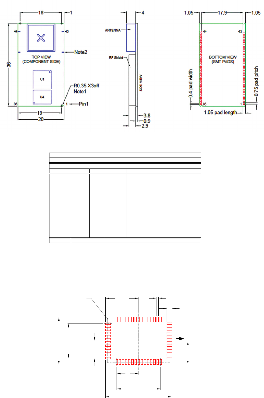
43
www.lairdtech.com
Laird Technologies
BTM520/521
Bluetooth® Multimedia Plus Module
MECHANICAL DETAILS
RECOMMENDED PCB FOOTPRINT
(all dimensions in mm)
1
12
13 27
28
54 40
39
34 RF OUT (See Note 1)
15.2
21.2
1x11
1x14
pin pitch
pin pitch
Pad Width 0.7 Typ
Pad Length 1.65 Typ
5.5
7
10.6
7.6
MODULE OUTLINE
(See note 2)
1
12
13 27
28
54 40
39
1
12
13 27
28
54 40
39
TOP VIEW
BOTTOM VIEW
(COMPONENT SIDE)
(SMT PADS)
E
D
34
34 RF OUT
RF OUT
SIDE VIEW
Description 54 pin BT Voice Module (8X6 Flash)
Size20.0 x 14.0 x 2.4mm
Pitch 1.0mm
Dimension Minimum Typical Maximum Notes
D1
E1
e
G
H
A1
A2
A
b
A2.42.7
A1 0.80.91.0
A2 1.51.7
b 0.60
D13.87 14.0 14.13
E 19.87 20.0 20.13
e1.0
D1 11.0
E1 14.0
F1.50
G3.00
PCB Thickness
RF Shield Height
Global pad width
Global pitch
2.3
H0.85 Global length of pad to edge of board
Units mm
Pin Outs
RF Shield
U1
U3
Orientation mark
on PCB and RF Shield
denotes pin 1
F
H
1.3
0.650.55
Pad Centre to Board edge
Pad Centre to Board edge
MECHANICAL
DRAWINGS
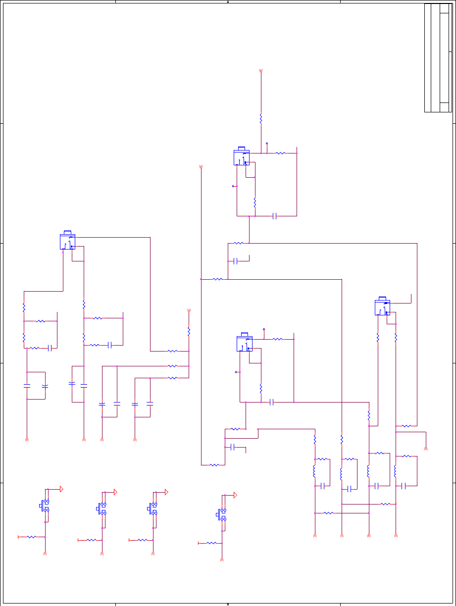
44
www.lairdtech.com
Laird Technologies
BTM520/521
Bluetooth® Multimedia Plus Module
5
5
4
4
3
3
2
2
1
1
D D
C C
BB
AA
AGND
AGND
AGND
AGND
AGND
AGND
AGND
AGND
AGND
AGND
AGND
VCC_IO
VCC_IO
VCC_IO
VCC_IO
SPKR_A_P
SPKR_A_N
SPKR_B_N
SPKR_B_P
MIC_BIAS
MIC_A_P
MIC_A_N
MIC_B_N
MIC_B_P
PIO_5/BT_STATE_BT_PRIORITY
PIO_7/RF_ACTIVE
PIO_6/WLAN_ACT
PIO_0/BT_ACTIVE
MIC_A_N_DIFF
AGND
MIC_A_N_DIFF
Title
Size Document Number Rev
Date: Sheet of
BTVMD-R-001-04 04
Mini Dev Board - Comms
C
1 3Friday, October 31, 2008
Title
Size Document Number Rev
Date: Sheet of
BTVMD-R-001-04 04
Mini Dev Board - Comms
C
1 3Friday, October 31, 2008
Title
Size Document Number Rev
Date: Sheet of
BTVMD-R-001-04 04
Mini Dev Board - Comms
C
1 3Friday, October 31, 2008
Single ended Stereo
Headphone Output
Single-ended stereo input
J3
NF 3 way 2.5mm audio jack
J3
NF 3 way 2.5mm audio jack
1
2
4
3
J1
3 way 2.5mm audio jack
J1
3 way 2.5mm audio jack
1
2
4
3
R38
NF 0R
R38
NF 0R
1 2
+
C35
NF 100u
+
C35
NF 100u
+
C32
NF 100u
+
C32
NF 100u
R4
39R
R4
39R
12
R30
2K2
R30
2K2
12
SW1
NF
SW1
NF
13
24
C7
NF 15pF
C7
NF 15pF
12
SW2
NF
SW2
NF
1 3
2 4
R16
0R
R16
0R
12
R25
NF 0R
R25
NF 0R
1 2
R2 0RR2 0R
12
+
C33
NF 100u
+
C33
NF 100u
R22
NF 0R
R22
NF 0R
12
J2
3 way 2.5mm audio jack
J2
3 way 2.5mm audio jack
1
2
4
3
C3
100u
C3
100u
1 2
SW3
NF
SW3
NF
13
24
R17
0R
R17
0R
12
C14
15pF
C14
15pF
12
R10
1MR
R10
1MR
1 2
R15
0R
R15
0R
12
R6
0R
R6
0R
1 2
SW4
NF
SW4
NF
13
24
TP3TP3
1
C12
15pF
C12
15pF
12
R9
39R
R9
39R
12
R29
0R
R29
0R
12
R36
2K2
R36
2K2
12
R18
10K
R18
10K
12
R24
NF 0R
R24
NF 0R
12
C9
NF 15pF
C9
NF 15pF
12
L3
15n
L3
15n
R37
7K5
R37
7K5
12
C5
100u
C5
100u
1 2
R23
NF 0R
R23
NF 0R
1 2
R14
0R
R14
0R
12
R5
1MR
R5
1MR
1 2
TP4TP4
1
R3
10K
R3
10K
12
R1
0R
R1
0R
12
R34
NF 0R
R34
NF 0R
1 2
C11
15pF
C11
15pF
12
J4
3 way 2.5mm audio jack
J4
3 way 2.5mm audio jack
1
2
4
3
C4
100n
C4
100n
12
R26
NF 0R
R26
NF 0R
12
R21
NF 0R
R21
NF 0R
12
C2
100n
C2
100n
12
R20
0R
R20
0R
12
R7 0RR7 0R
12
R32
0R
R32
0R
12
L1
15n
L1
15n
R39
NF 0R
R39
NF 0R
12
TP1TP1
1
R28
NF 0R
R28
NF 0R
12
C13
15pF
C13
15pF
12
R35
7K5
R35
7K5
12
C6
100u
C6
100u
1 2
+
C34
NF 100u
+
C34
NF 100u
R33
NF 0R
R33
NF 0R
1 2
TP2TP2
1
R8
10K
R8
10K
12
R13
10K
R13
10K
12
C1
100u
C1
100u
12
L4
15n
L4
15n
R19
NF 0R
R19
NF 0R
12
R27
0R
R27
0R
12
L2
15n
L2
15n
R31
NF 0R
R31
NF 0R
1 2
C10
NF 15pF
C10
NF 15pF
12
C8
NF 15pF
C8
NF 15pF
12
MECHANICAL
DRAWINGS
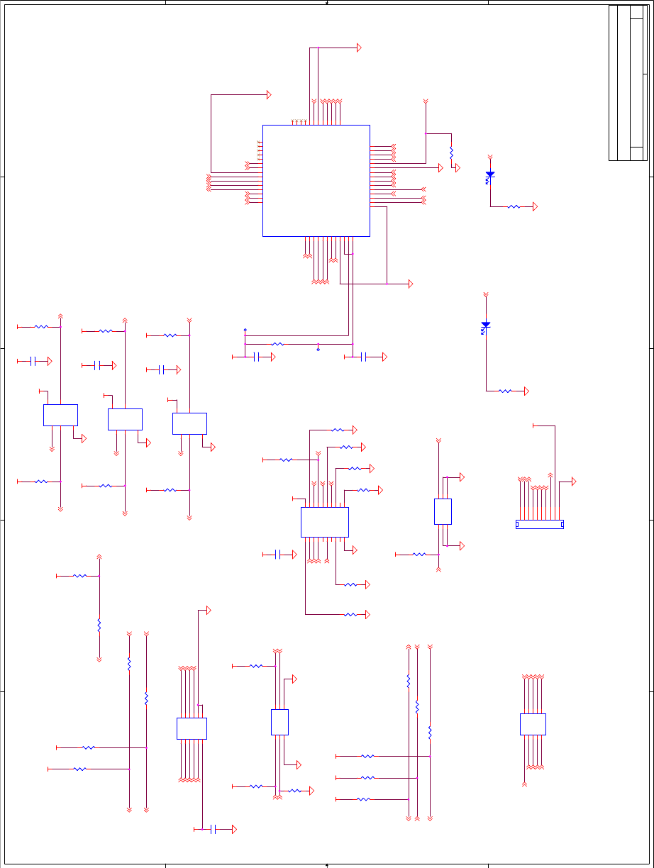
45
www.lairdtech.com
Laird Technologies
BTM520/521
Bluetooth® Multimedia Plus Module
5
5
4
4
3
3
2
2
1
1
D D
C C
BB
AA
AGND
AGND
VCC_IO
VCC_3V3
VCC_IO
VCC_3V3 VCC_3V3
VCC_3V3
VCC_3V3
VCC_IO VCC_IO
VCC_3V3
VCC_IO
VCC_3V3
VCC_3V3
VCC_IO
VCC_IO VCC_IO
VCC_3V3
VCC_3V3
VCC_3V3
VCC_3V3
VCC_3V3
VCC_3V3
VCC_3V3
VCC_3V3
VCC_3V3
VDD_CONN
VCC_3V3
VCC_IO
USB_DSR
USB_DCD
USB_CTS
PIO_1/DCD
Module_TX USB_RX
SPI_CLK_PC
SPI_CS_PC
SPI_MISO_PC
SPI_MOSI_PC
PCM_IN
PCM_CLK
PCM_SYNC
Module_RTS
Module_TX
RESET_ Module_RX
Module_CTS
PIO_3/RI
PIO_1/DCD
PIO_3/RI USB_PIO_3/RI
PIO_2/DSR
PIO_5/DTR
Module_RTS
PCM_CLK
PCM_OUT
Module_CTS
PCM_SYNC
Module_RTS
SPKR_A_N
SPI_MOSI
LED EXT1
LED EXT0
SPKR_A_P
SPKR_B_P
PIO_0/BT_ACTIVE
SPKR_B_N
MIC_BIAS
ANT
MIC_B_P
MIC_A_N
MIC_A_P
MIC_B_N
PIO_7/RF_ACTIVE
USB_MOD_D+
PIO_6/WLAN_ACT
USB_MOD_D-
RESET_
SPI_MISO
SPI_CS
PIO_5/BT_STATE_BT_PRIORITY
PIO_5/DTR
PIO_2/DSR
PIO_3/RI
PIO_1/DCD
SPI_CLK
PCM_IN
Module_RX
Module_TX
SPI_CLK_PC
SPI_CS_PC
SPI_CS
SPI_CLK
SPI_MOSI_PC
SPI_MOSI
SPI_MISO_PC
SPI_MISO
AGND
LED EXT1
USB_MOD_D+
LED EXT0
USB_MOD_D-
USB_TX Module_RX
Module_CTSUSB_RTS
USB_DTR
FTDI_EN
FTDI_EN
FTDI_EN
FTDI_EN
USB_PWREN
MIC_BIAS
SPKR_B_P
MIC_B_N
SPKR_A_P
MIC_B_P
MIC_A_N MIC_A_P
SPKR_A_N
SPKR_B_N
PCM_OUT
AGND
PIO_2/DSR
PIO_5/DTR
PIO_2/DSR
PIO_3/RI
PIO_1/DCD
PIO_5/DTR
Title
Size Document Number Rev
Date: Sheet of
BTVMD-R-001-04 04
Mini Dev Board - Comms
C
2 3Friday, October 31, 2008
Title
Size Document Number Rev
Date: Sheet of
BTVMD-R-001-04 04
Mini Dev Board - Comms
C
2 3Friday, October 31, 2008
Title
Size Document Number Rev
Date: Sheet of
BTVMD-R-001-04 04
Mini Dev Board - Comms
C
2 3Friday, October 31, 2008
R51
10K
R51
10K
12
D1
HSMC-A100-Q00J1
D1
HSMC-A100-Q00J1
2
1
R41
10K
R41
10K
12
U1
NC7SZ125
U1
NC7SZ125
OE_
1
IN
2
GND
3
OUT 4
VCC 5
U4
CONN_SM_54
U4
CONN_SM_54
PIO_15/DTR
1
PIO_5/BT_STATE/BT_PRIORITY
2
PCM_IN
3
PCM_OUT
4
PCM_SYNC
5
PCM_CLK
6
VDD_USB
10
VDD_IO
11
MASTER_VIN
12
SPI_CS
14
SPI_MISO
15
SPI_CLK
16
SPI_MOSI
17
PIO_2/DSR
18
LED_EXT1
7
LED_EXT0
8
PIO_0/BT_ACTIVE
21
GND2
22
AUDIO_GND
23
SPKR_A_N
24
SPKR_A_P
25
SPKR_B_N
26
SPKR_B_P
27
MIC_BIAS 28
BC05_RST 54
PIO_6/WLAN_ACTIVE 53
USB_D+ 46
USB_D- 45
PIO_7/RF_ACTIVE 52
GND447
UART_RTS 48
UART_CTS 49
NC444
NC543
NC642
NC15 41
NC14 40
NC13 39
NC12 38
NC11 37
NC10 36
ANT 34
NC9 35
NC8 33
MIC_AN_C 32
MIC_AP_C 31
MIC_BN_C 30
MIC_BP_C 29
UART_RX 51
UART_TX 50
GND1
9
GND3
13
PIO_3/RI
19
PIO_1/DCD
20
R71
130R
R71
130R
1 2
R47
10K
R47
10K
12
R54
0R
R54
0R
1 2
R65
10K
R65
10K
12
R66 0R
R66 0R
12
JP4
NF
JP4
NF
12
34
56
7 8
9 10
R63
10K
R63
10K
1 2
R40
10K
R40
10K
1 2
R57
10K
R57
10K
1 2
R68
0R
R68
0R
12
C15
100n
C15
100n
12
R50
10K
R50
10K
1 2
C21
100n
C21
100n
12
R43
10K
R43
10K
12
R55
10K
R55
10K
12
D2
HSMC-A100-Q00J1
D2
HSMC-A100-Q00J1
2
1
U2
NC7SZ125
U2
NC7SZ125
OE_
1
IN
2
GND
3
OUT 4
VCC 5
R46
10K
R46
10K
1 2
R100
1K5
R100
1K5
12
R62
10K
R62
10K
12
TP5TP5
1
R69
0R
R69
0R
1
2
R67
0R
R67
0R
12
JP3
NF
JP3
NF
1
3
56
4
2
R60
10K
R60
10K
1 2
R52
10K
R52
10K
12
C19
100n
C19
100n
12
R59
10K
R59
10K
1 2
C17
100n
C17
100n
12
U3
NC7SZ125
U3
NC7SZ125
OE_
1
IN
2
GND
3
OUT 4
VCC 5
R45
0R
R45
0R
1 2
R42
10K
R42
10K
12
JP2
NF
JP2
NF
1
3
5 6
4
2
JP1
NF Header 6X2
JP1
NF Header 6X2
1 2
3 4
5 6
78
910
11 12
C18
100n
C18
100n
12
C16
100n
C16
100n
12
R58
10K
R58
10K
1 2
U5
74LCX244
U5
74LCX244
OE1_
1
I0
2
O4
3
I1
4
O5
5
I2
6
O6
7
I3
8
O7
9
GND
10 I7 11
O3 12
I6 13
O2 14
I5 15
O1 16
I4 17
O0 18
OE2_ 19
VCC 20
R44
10K
R44
10K
12
R49
0R
R49
0R
1 2
R64
10K
R64
10K
12
R61
10K
R61
10K
1 2
R56
10K
R56
10K
1 2
J5
HEADER 10 X 1
J5
HEADER 10 X 1
1
2
3
4
5
6
7
8
9
10
C20
100n
C20
100n
12
R48 0R
R48 0R
1 2
R53
10K
R53
10K
12
TP6TP6
1
R70
130R
R70
130R
1 2
MECHANICAL
DRAWINGS
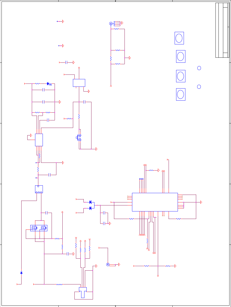
46
www.lairdtech.com
Laird Technologies
BTM520/521
Bluetooth® Multimedia Plus Module
5
5
4
4
3
3
2
2
1
1
D D
C C
BB
AA
D-
50ohm Track 50_ohm Track
D+
VDD_3V3_IO
VDD_USB
VDD_3V3_IO
VDD_CONN
VDD_USB
VCC_3V3
VCC_3V3
VCC_3V3
VDD_CONN
VDD_USB
VCC_3V3
VCC_3V3
USB-
USB+
USB_PWREN
USB_SLEEP
USB_RTS
USB_CTS
USB_RX
USB_TX
USB-
USB+
USB_PWREN
RESET_FTDI
USB_DTR
USB_DSR
USB_DCD
USB_PIO_3/RI
RESET_
ANT
USB_MOD_D+
USB_MOD_D-
Title
Size Document Number Rev
Date: Sheet of
BTVMD-R-001-04 04
Mini_Dev_Power_Supplies
C
3 3Friday, October 31, 2008
Title
Size Document Number Rev
Date: Sheet of
BTVMD-R-001-04 04
Mini_Dev_Power_Supplies
C
3 3Friday, October 31, 2008
Title
Size Document Number Rev
Date: Sheet of
BTVMD-R-001-04 04
Mini_Dev_Power_Supplies
C
3 3Friday, October 31, 2008
M3
Mounting Hole
M3
Mounting Hole
J6
SMA_Vert
J6
SMA_Vert
1
2
3
4
5
C23
100n
C23
100n
12
TP12
TH_TEST_POINT
TP12
TH_TEST_POINT
1
C25
10N
C25
10N
12
R74
0.1R 0805
R74
0.1R 0805
12
C30
1n
C30
1n
12
R85 N/FR85 N/F
12
R79
10K
R79
10K
1 2
R72
9K1
R72
9K1
12
D5
HSMG-A100-HO1J1
D5
HSMG-A100-HO1J1
21
R76
1K3
R76
1K3
12
C28
NF
C28
NF
12
M2
Mounting Hole
M2
Mounting Hole
R94 NF 0RR94 NF 0R
1 2
R86
10K
R86
10K
1 2
C24
100n
C24
100n
12
M1
Mounting Hole
M1
Mounting Hole
R84
10K
R84
10K
1 2
R73
110R
R73
110R
12
R90
0R
R90
0R
1 2
L5
BLM18PG221SN1D
L5
BLM18PG221SN1D
1 2
FID2
Fiducial
FID2
Fiducial
D3
Diode_S1A
D3
Diode_S1A
1 2
R11
NF 9K1
R11
NF 9K1
12
CN1
DC Power jack_2.1mm
CN1
DC Power jack_2.1mm
1
2
3
R77
1K
R77
1K
1 2
R91
NF 9K1
R91
NF 9K1
12
R81 0RR81 0R
12
U6
MCP1726-ADJE/MF
U6
MCP1726-ADJE/MF
Vin_1
1
Vin_2
2
/SHDN
3
GND
4PWRGD 5
Cdelay 6
ADJ 7
Vout 8
GND 9
R88
4K7
R88
4K7
12
C27
100n
C27
100n
12
Q1 IRF5810
Q1 IRF5810
1
56
42
3
C22
2u2
C22
2u2
12
TP7TP7
1
R78
10K
R78
10K
12
R80
1K
R80
1K
1 2
TP15TP15
FID1
Fiducial
FID1
Fiducial
TP11
TH_TEST_POINT
TP11
TH_TEST_POINT
1
R87
10K
R87
10K
12
OFF
SW5
3 position switch
OFF
SW5
3 position switch
2
1
3
JP5
-
USB B
JP5
-
USB B
Vcc 1
D- 2
D+ 3
GND 4
55
6
6
TP8TP8
1
D6
BAT54C
D6
BAT54C
1
2
3
R75 10KR75 10K
12
R93 NF 0RR93 NF 0R
1 2
C29
100n
C29
100n
12
U8
FT232R
U8
FT232R
TXD
30
DTR#
31
RTS#
32
VCCIO 1
RXD
2
RI#
3
GND
4
DSR#
6
DCD#
7
CTS#
8
CBUS3 11
CBUS2 10
OSCO
28 OSCI
27
TEST
26
AGND
24
CBUS1 21
CBUS4 9
GND
20 VCC 19
RESET#
18
GND
17
3V3OUT 16
USBDM 15
USBDP 14
NC_5
5
NC_4
12
NC_6
13
CBUS0 22
NC_1 23
NC_2 25
NC_3 29
THPAD
33
R83
4.7K
R83
4.7K
12
SW6
BFS-1000
SW6
BFS-1000
13
2 4
M4
Mounting Hole
M4
Mounting Hole
TP13TP13
R82 0RR82 0R
1 2
TP14TP14
R92
NF 9K1
R92
NF 9K1
12
C26
2u2
C26
2u2
12
U7
NC7SV17
U7
NC7SV17
NC1
1
IN
2
GND
3
OUT 4
VCC 5
C31
100n
C31
100n
12
MECHANICAL
DRAWINGS
47
BTM520/521
Bluetooth® Multimedia Plus Module
global solutions:
local support
TM
USA: +1.800.492.2320
Europe: +44.1628.858.940
Asia: +852.2268.6567
wirelessinfo@lairdtech.com
www.lairdtech.com/wireless
ORDERING INFORMATION
BTM520 Bluetooth® Multimedia Plus Module (external antenna)
BTM521 Bluetooth® Multimedia Plus Module with integrated antenna
DVK-BTM520 Development Board with BTM520 soldered in place
DVK-BTM521 Development Board with BTM521 soldered in place
GENERAL COMMENTS
This is a preliminary user manual. Please check with Laird Technologies for the latest information before
commencing a design. If in doubt, ask.
Refer to the schematic BTV-R-003.pdf for the Development Kit for examples of typical pin connections.
A pdf of the schematic can be downloaded from the product web page.
ORDERING
INFORMATION

48
Laird Technologies is the world leader in the design and
manufacture of customized, performance-critical products for
wireless and other advanced electronics applications.
Laird Technologies partners with its customers to nd
solutions for applications in various industries such as:
Network Equipment
Telecommunications
Data Communications
Automotive Electronics
Computers
Aerospace
Military
Medical Equipment
Consumer Electronics
Laird Technologies offers its customers unique
product solutions, dedication to research and
development, as well as a seamless network of
manufacturing and customer support
facilities across the globe.
LWS-UM-BTM520-521 0509
Copyright © 2009 Laid Technologies, Inc. All rights reserved.
The information contained in this manual and the accompanying software programs are copyrighted and all rights are reserved by Laird Technologies, Inc. Laird Technologies, Inc. reserves the right to make periodic
modications of this product without obligation to notify any person or entity of such revision. Copying, duplicating, selling, or otherwise distributing any part of this product or accompanying documentation/software
without the prior consent of an authorized representative of Laird Technologies,Inc. is strictly prohibited.
All brands and product names in this publication are registered trademarks or trademarks of their respective holders.
This material is preliminary
Information furnished by Laird Technologies in this specication is believed to be accurate. Devices sold by Laird Technologies are covered by the warranty and patent indemnication provisions appearing in its Terms
of Sale only. Laird Technologies makes no warranty, express, statutory, and implied or by description, regarding the information set forth herein. Laird Technologies reserves the right to change specications at any
time and without notice. Laird Technologies’ products are intended for use in normal commercial and industrial applications. Applications requiring unusual environmental requirements such as military, medical life-
support or life-sustaining equipment are specically not recommended without additional testing for such application.
Limited Warranty, Disclaimer, Limitation of Liability
For a period of one (1) year from the date of purchase by the OEM customer, Laird Technologies warrants the OEM transceiver against defects in materials and workmanship. Laird Technologies will not honor this
warranty (and this warranty will be automatically void) if there has been any (1) tampering, signs of tampering; 2) repair or attempt to repair by anyone other than an Laird Technologies authorized technician. This
warranty does not cover and Laird Technologies will not be liable for, any damage or failure caused by misuse, abuse, acts of God, accidents, electrical irregularity, or other causes beyond Laird Technologies’ control,
or claim by other than the original purchaser. In no event shall Laird Technologies be responsible or liable for any damages arising: From the use of product; From the loss of use, revenue or prot of the product; or
As a result of any event, circumstance, action, or abuse beyond the control of Laird Technologies, whether such damages be direct, indirect, consequential, special or otherwise and whether such damages are incurred
by the person to whom this warranty extends or third party. If, after inspection, Laird Technologies’ determines that there is a defect, Laird Technologies will repair or replace the OEM transceiver at their discretion. If
the product is replaced, it may be a new or refurbished product.