Ezurio BL600 BL600 Series Bluetooth Low Energy Module User Manual

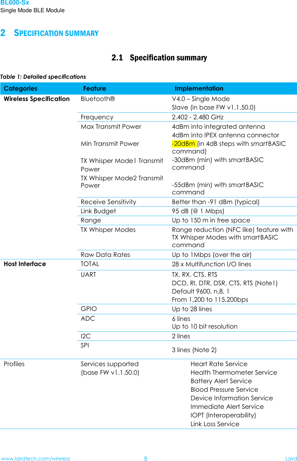
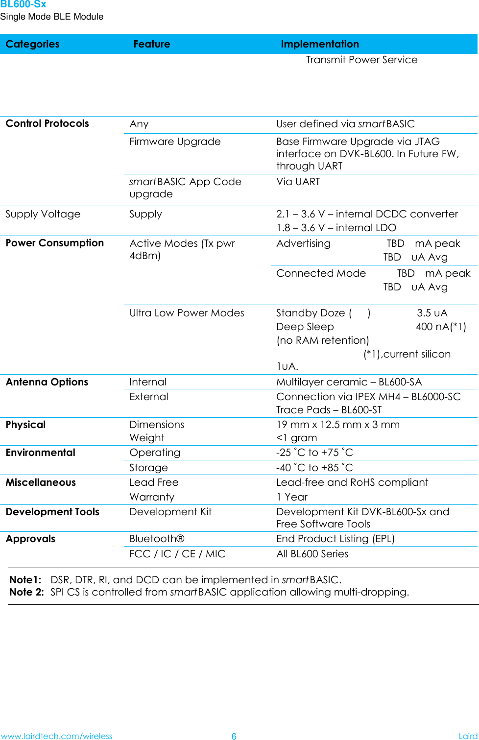
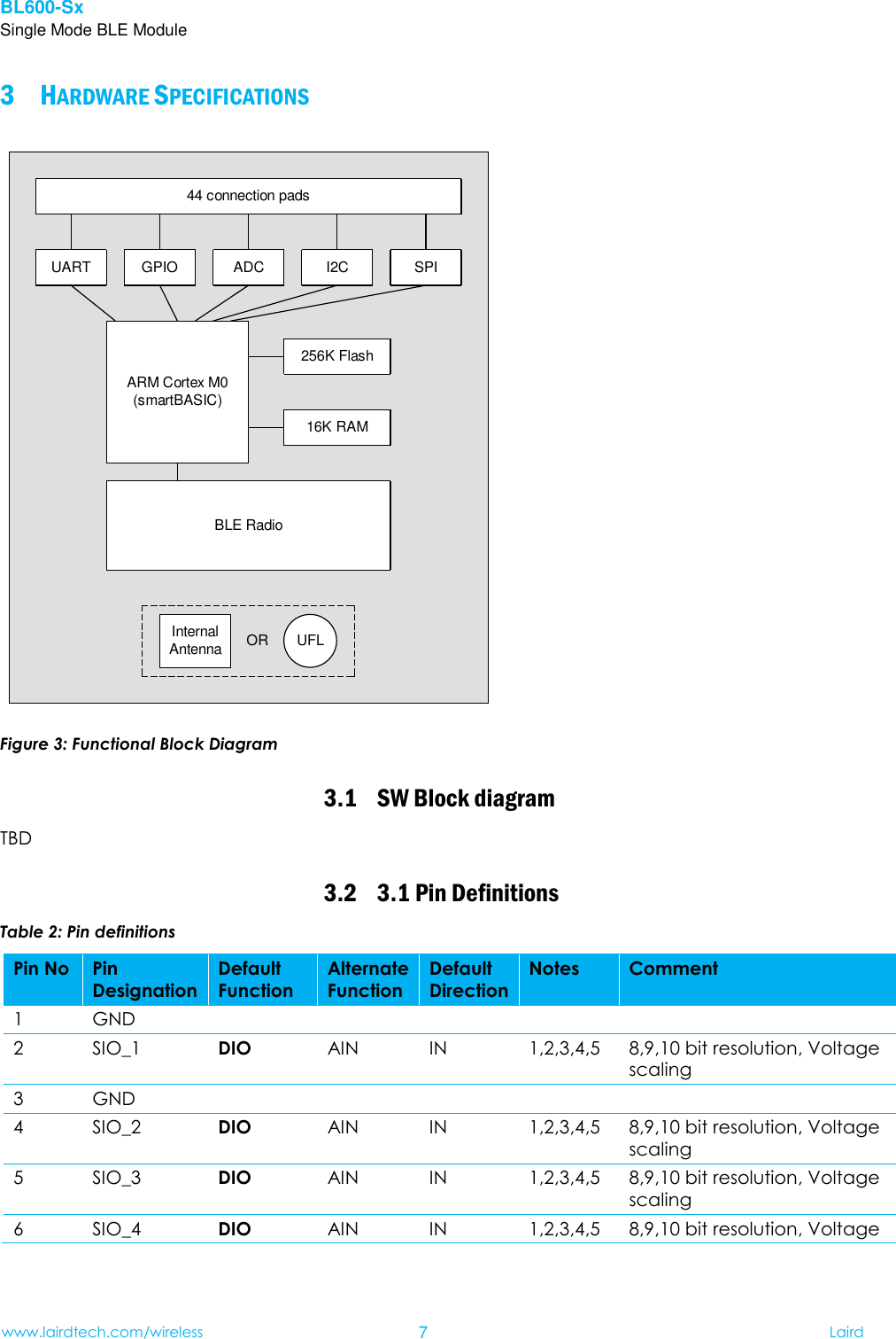
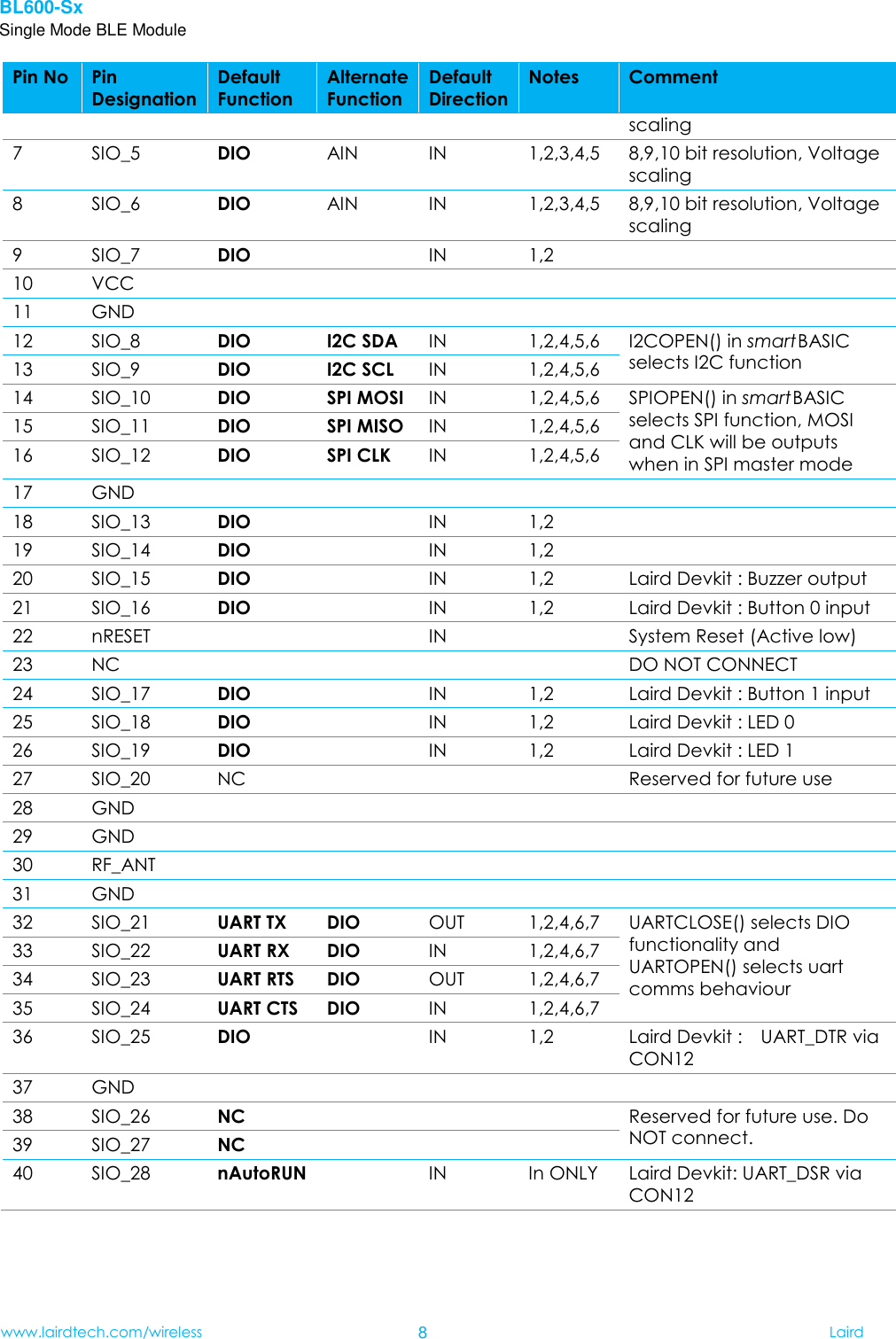
Ezurio Ltd BL600 Series Bluetooth Low Energy Module

User Manual

      Single Mode Bluetooth Low Energy (BLE) Module Part # BL600-SA, BL600-SC, BL600-ST HARDWARE DATA SHEET AND INTEGRATION GUIDE VERSION 0.5         Americas: +1-800-492-2320 Option 3 Europe: +44-1628-858-940 Hong Kong: +852-2923-0610
BL600-Sx Single Mode BLE Module www.lairdtech.com/wireless 2 Laird    www.lairdtech.com/wireless   REVISION HISTORY Revision Description Version 0.1 07/02/2013 – first stage internal release Version 0.2 07/02/13 – includes Mt comments Version 0.3 15Feb13 –RK initial updates in blue colour.    (need to clear it with Nordic how much of the data In their chipset specification we can copy over to our module specification. . Version 0.4 22Mar13 –RK re-write thoroughly.    When reviewed, need to clear it with Nordic how much of the data In their chipset specification we can copy over to our module specification. Version 0.5 Modify TCB Review Feedback
BL600-Sx Single Mode BLE Module www.lairdtech.com/wireless 3 Laird    CONTENTS Revision History .......................................................................................................................... 2 Contents ..................................................................................................................................... 3  Overview and Key Features .................................................................................................... 4 1 Specification summary .......................................................................................................... 5 2 Hardware Specifications ........................................................................................................ 7 3 Power Consumption ............................................................................................................ 11 4 Functional Description ........................................................................................................ 15 55.1 Power management (includes brown-out and power on reset) ..................................... 15 5.2 Clocks ........................................................................................................................................... 15 5.3 Memory for smart BASIC application code .......................................................................... 16 5.4 RF ................................................................................................................................................... 16 5.5 UART Interface ............................................................................................................................ 16 5.6 SPI Bus ........................................................................................................................................... 17 5.7 I2C Interface ............................................................................................................................... 17 5.8 General Purpose I/O and ADC ............................................................................................... 18  HW integration guide .......................................................................................................... 20 66.1 Circuit Components Required on Host PCB ......................................................................... 20 6.2 BL600-Sx General PCB Layout on Host PCB........................................................................... 20 6.3 BL600-SA Layout on Host PCB .................................................................................................. 20 6.4 BL600-ST Layout on Host PCB ................................................................................................... 21  Tools For development of applications ................................................................................ 22 7 Application Note for Surface Mount Modules ...................................................................... 23 88.1 Introduction ................................................................................................................................. 23 8.2 Shipping ....................................................................................................................................... 23 8.3 Reflow Parameters ..................................................................................................................... 24  FCC and IC Regulatory Statments ........................................................................................ 25 9 Japan (MIC) Regulatory ........................................................................................................ 29 10 CE Regulatory ...................................................................................................................... 29 11 EU DECLARATIONS OF CONFORMITY ................................................................................... 29 12 Mechanical Details .............................................................................................................. 32 13 ORDERING INFORMATION .................................................................................................... 33 14 Bluetooth SIG Approvals ...................................................................................................... 34 1515.1 End Product Listings (EPLs) ........................................................................................................ 34
BL600-Sx Single Mode BLE Module www.lairdtech.com/wireless 4 Laird     OVERVIEW AND KEY FEATURES 1Every BL600 Series module is designed to enable OEMs to add single-mode Bluetooth Low Energy (BLE) to small, portable, power –conscious devices. The BL600 modules are enabled with Laird’s smart BASIC, an event-driven programming language that enables OEMs to make their BLE product development quicker, and simpler, significantly reducing time to market. Smart BASIC enables customers to develop a complete embedded application inside the compact BL600 hardware, connecting to a wide array of external sensors via its I2C, SPI, UART, ADC or GPIO interfaces. Based on the world-leading Nordic Semiconductor nRF51822 chipset, the BL600 modules provide ultra-low power consumption with outstanding wireless range via 4dBm of transmit power. A broad range of BLE profiles including Temperature and Heart Rate are available and smart BASIC provides the ideal mechanism to support any BLE profile development of your choice.   Features & Benefits   Application Areas  Bluetooth v4.0 - Single Mode  External or Internal Antennas  smart BASIC programming language    Full Bluetooth EPL  Compact Footprint  Class 2 output - 4dBm  UART, GPIO, ADC, I2C and SPI interfaces  Fast Time to Market  FCC, CE, IC certified and other regulatory certifications on request  No external components needed  Medical devices  Wellness devices  iOS ‘appcessories’  Fitness sensors    Location Awareness  Home automation 
BL600-Sx Single Mode BLE Module www.lairdtech.com/wireless 5 Laird     SPECIFICATION SUMMARY 22.1 Specification summary Table 1: Detailed specifications Categories Feature Implementation Wireless Specification Bluetooth®  V4.0 – Single Mode Slave (in base FW v1.1.50.0) Frequency 2.402 - 2.480 GHz Max Transmit Power  Min Transmit Power  TX Whisper Mode1 Transmit Power TX Whisper Mode2 Transmit Power 4dBm into integrated antenna 4dBm into IPEX antenna connector -20dBm (in 4dB steps with smart BASIC command) -30dBm (min) with smart BASIC command  -55dBm (min) with smart BASIC command Receive Sensitivity Better than -91 dBm (typical) Link Budget 95 dB (@ 1 Mbps) Range Up to 150 m in free space TX Whisper Modes Range reduction (NFC like) feature with TX Whisper Modes with smart BASIC command Raw Data Rates Up to 1Mbps (over the air) Host Interface TOTAL 28 x Multifunction I/O lines UART TX, RX, CTS, RTS DCD, RI, DTR, DSR, CTS, RTS (Note1) Default 9600, n,8, 1 From 1,200 to 115,200bps GPIO Up to 28 lines ADC 6 lines   Up to 10 bit resolution   I2C 2 lines SPI 3 lines (Note 2) Profiles    Services supported (base FW v1.1.50.0) Heart Rate Service Health Thermometer Service Battery Alert Service                                                         Blood Pressure Service Device Information Service Immediate Alert Service IOPT (Interoperability) Link Loss Service
BL600-Sx Single Mode BLE Module www.lairdtech.com/wireless 6 Laird    Categories Feature Implementation Transmit Power Service                                                     Control Protocols   Any     User defined via smart BASIC Firmware Upgrade Base Firmware Upgrade via JTAG interface on DVK-BL600. In Future FW, through UART   smart BASIC App Code upgrade     Via UART Supply Voltage Supply 2.1 – 3.6 V – internal DCDC converter 1.8 – 3.6 V – internal LDO Power Consumption Active Modes (Tx pwr 4dBm)    Advertising                      TBD    mA peak                                           TBD    uA Avg   Connected Mode      TBD  mA peak                      TBD  uA Avg Ultra Low Power Modes  Standby Doze (      )                  3.5 uA Deep Sleep                                400 nA(*1)                                         (no RAM retention)                                                     (*1),current silicon 1uA. Antenna Options Internal Multilayer ceramic – BL600-SA External Connection via IPEX MH4 – BL6000-SC Trace Pads – BL600-ST Physical Dimensions Weight 19 mm x 12.5 mm x 3 mm   <1 gram Environmental Operating -25 ˚C to +75 ˚C  Storage -40 ˚C to +85 ˚C Miscellaneous Lead Free Lead-free and RoHS compliant Warranty 1 Year Development Tools Development Kit Development Kit DVK-BL600-Sx and Free Software Tools Approvals Bluetooth®  End Product Listing (EPL) FCC / IC / CE / MIC All BL600 Series Note1:  DSR, DTR, RI, and DCD can be implemented in smart BASIC. Note 2:   SPI CS is controlled from smart BASIC application allowing multi-dropping.
BL600-Sx Single Mode BLE Module www.lairdtech.com/wireless 7 Laird     HARDWARE SPECIFICATIONS 344 connection padsUART GPIO ADC I2C SPI16K RAM256K FlashBLE RadioOR UFLInternalAntennaARM Cortex M0(smartBASIC) Figure 3: Functional Block Diagram 3.1 SW Block diagram TBD 3.2 3.1 Pin Definitions Table 2: Pin definitions Pin No Pin Designation Default Function Alternate Function Default Direction Notes Comment 1 GND           2 SIO_1 DIO AIN IN 1,2,3,4,5 8,9,10 bit resolution, Voltage scaling 3 GND           4 SIO_2 DIO AIN IN 1,2,3,4,5 8,9,10 bit resolution, Voltage scaling 5 SIO_3 DIO AIN IN 1,2,3,4,5 8,9,10 bit resolution, Voltage scaling 6 SIO_4 DIO AIN IN 1,2,3,4,5 8,9,10 bit resolution, Voltage
BL600-Sx Single Mode BLE Module www.lairdtech.com/wireless 8 Laird    Pin No Pin Designation Default Function Alternate Function Default Direction Notes Comment scaling 7 SIO_5 DIO AIN IN 1,2,3,4,5 8,9,10 bit resolution, Voltage scaling 8 SIO_6 DIO AIN IN 1,2,3,4,5 8,9,10 bit resolution, Voltage scaling                                                         9 SIO_7 DIO   IN 1,2   10 VCC           11 GND           12 SIO_8 DIO I2C SDA IN 1,2,4,5,6 I2COPEN() in smart BASIC selects I2C function 13 SIO_9 DIO I2C SCL IN 1,2,4,5,6 14 SIO_10 DIO SPI MOSI IN 1,2,4,5,6 SPIOPEN() in smart BASIC selects SPI function, MOSI and CLK will be outputs when in SPI master mode 15 SIO_11 DIO SPI MISO IN 1,2,4,5,6 16 SIO_12 DIO SPI CLK IN 1,2,4,5,6 17 GND          18 SIO_13 DIO   IN 1,2   19 SIO_14 DIO   IN 1,2   20 SIO_15 DIO   IN 1,2 Laird Devkit : Buzzer output 21 SIO_16 DIO   IN 1,2 Laird Devkit : Button 0 input 22 nRESET     IN   System Reset (Active low) 23 NC         DO NOT CONNECT 24 SIO_17 DIO   IN 1,2 Laird Devkit : Button 1 input 25 SIO_18 DIO   IN 1,2 Laird Devkit : LED 0 26 SIO_19 DIO   IN 1,2 Laird Devkit : LED 1 27 SIO_20 NC       Reserved for future use 28 GND           29 GND           30 RF_ANT           31 GND           32 SIO_21 UART TX DIO OUT 1,2,4,6,7 UARTCLOSE() selects DIO functionality and UARTOPEN() selects uart comms behaviour 33 SIO_22 UART RX DIO IN 1,2,4,6,7 34 SIO_23 UART RTS DIO OUT 1,2,4,6,7 35 SIO_24 UART CTS DIO IN 1,2,4,6,7 36 SIO_25 DIO   IN 1,2 Laird Devkit :    UART_DTR via CON12 37 GND          38 SIO_26 NC       Reserved for future use. Do NOT connect. 39 SIO_27 NC       40 SIO_28 nAutoRUN   IN   In ONLY Laird Devkit: UART_DSR via CON12
BL600-Sx Single Mode BLE Module www.lairdtech.com/wireless 9 Laird    Pin No Pin Designation Default Function Alternate Function Default Direction Notes Comment 41 SIO_29 DIO   IN 1,2 Laird Devkit :    UART_DCD via CON12 42 SIO_30 DIO   IN 1,2 Laird Devkit :    UART_RI via CON12 43 GND          44 SIO_0 DIO   IN 1,2   Notes:  1. Secondary function is selectable in smart BASIC BASIC application 2. DIO = Digital Input or Output 3. AIN = Analog Input 4. DIO or AIN functionality is selected using the GpioSetFunc() function in smart BASIC 5. AIN configuration selected using GpioSetFunc() function 6. I2C, UART, SPI controlled by xxxOPEN() functions in smart BASIC 7. SIO_21 to SIO_24 are DIO by default when $autorun$ app runs on power up. SIO lines can be configured through smart BASIC to be either inputs or outputs with weak or strong pull-ups or pull-downs.   At reset, all SIO lines are configured as the defaults shown above. In other words, BL600 module shipped form production the loaded base FW, all the SIO pins (with “default function” of “DIO” are inputs).   UART_RX, UART_TX, UART_CTS are all 3.3 v level logic. For example, when RX and TX are idle they will be sitting at 3.3V. Conversely for handshaking pins CTS and RTS at 0v is treated as an assertion. Pin 40 (nAutoRUN) is an input, with active low logic. In the development kit (DVK-BL600-sx) it is connected so that the state is driven by the host’s DTR output line. 3.3 Electrical Specifications 3.3.1 Absolute Maximum ratings Absolute maximum ratings for supply voltage and voltages on digital and analogue pins of the Module are listed below; exceeding these values will cause permanent damage. Parameter Min Max Unit Voltage at VCC pin -0.3 +3.6 V Voltage at GND pin    0 V Voltage at SIO pin   -0.3 VCC+0.3 V Storage temperature -40 +85 ºC
BL600-Sx Single Mode BLE Module www.lairdtech.com/wireless 10 Laird    3.3.2 Recommended Operating Parameters 3.3.2.1 Power Supply Parameter Min Typ Max Unit VCC   1.8 3 3.6 V VCC (with internal DCDC enabled) 2.1 3 3.6 V VCC rise time (0 to 1.8V)  Note1   60 mS Operating Temperature Range -25 25 +75 ºC  Note:    The on-chip power-on reset circuitry may not work properly for rise times outside the noted interval. 3.3.2.2 Signal Levels for Interface, SIO   Parameter Min Typ Max Unit VIH    Input high voltage 0.7VCC  VCC V VIL    Input low voltage VSS  3.6 V VOH Output high voltage               (std. drive, 0.5mA)             (high-drive, 5mA) Note2  VCC-0.3 VCC-0.3   VCC VCC  V V VOL Output low voltage             (std. drive, 0.5mA)             (high-drive, 5mA)  VSS VSS   0.3 0.3  V V Note:    Maximum number of pins with 5mA high drive is 3. 3.3.2.3 ADC specification Parameter Min Typ Max Unit ADC Internal reference voltage   -1.5% 1.2V +1.5% % ADC pin input   internal selectable scaling    1/1 1/3 2/3  scaling   ADC input pin voltage maximum (w.r.t scaling) 1/1 1/3 2/3 Checking with     NORDIC     1.2 VCC/3 VCC(2/3)   V Time required to convert    single sample in 10bit mode (see note)  68  Us Time required to convert    single sample in 9bit mode  36  us Time required to convert    single sample in 8bit mode  20  us
BL600-Sx Single Mode BLE Module www.lairdtech.com/wireless 11 Laird    Note:    Current production FW (v1.1.50.0) allows only 10bit mode.     POWER CONSUMPTION 44.1 Power Consumption Parameter Min Typ Max Unit Active mode (Advertising or Connection) TX only run peak current @TXpwr= +4dBm   TX only run peak current @TXpwr=    0dBm   TX only run peak current @TXpwr= -4dBm   TX only run peak current @TXpwr= -8dBm   TX only run peak current @TXpwr= -12dBm TX only run peak current @TXpwr= -16dBm   TX only run peak current @TXpwr= -20dBm TX Whisper mode 1 TX only run peak current @TXpwr= -30dBm TX Whisper mode 2 TX only run peak current @TXpwr= -55dBm   16 10.5 8 7 6.5 6 5.5  5.5  Need to measure   mA mA mA mA mA mA mA  mA Active Mode         RX only current   13   mA   Ultra Low Power Mode1  (note1)   Standby Doze       Standby Doze (UART on)   3.5   1.33mA to be measured again   uA Ultra Low Power Mode2  Note2   Deep Sleep (no RAM retention)   Deep Sleep (8kB RAM retention)   Deep Sleep (16kB RAM retention)   400 600 800   nA nA nA Note 1:   In Standby Doze, all functional blocks independently are in IDLE or RUN mode depending on needed functionality. All peripherals that are enabled stay on and may wake the chip again. Depending on active peripherals, current consumption will be from ~2-3 µA up to > 1 mA.   See individual peripherals current consumption in Table xx on page. Note 2:    In Deep Sleep everything is disabled and the only wake-up sources are reset and change on pins on which sense is enabled. The current consumption is ~1000nA to 1200nA (in current Nordic silicon). Current base FW ((v1.1.50.0) allows coming out of
BL600-Sx Single Mode BLE Module www.lairdtech.com/wireless 12 Laird    deep sleep through HW reset only. Future FW release will allow coming out from Deep Sleep to Standby Doze through GPIO signal or HW reset.
BL600-Sx Single Mode BLE Module www.lairdtech.com/wireless 13 Laird    4.2 Measured waveforms   TBD Figure xx    Typical current consumption profile during advertising in slave mode @ Tx pwr +4dBm Figure X: Typical current consumption profile during advertising in slave mode @ Tx pwr -30dBm (TX Whisper Mode1) Figure X: Typical current consumption profile during advertising in slave mode @ Tx pwr -55dBm (TX Whisper Mode2) Measured waveform Figure X: Typical current consumption profile during data connection in slave mode@ Tx pwr +4dBm (TX Whisper Mode1) Figure X: Typical current consumption profile during data connection in slave mode@ Tx pwr -30dBm (TX Whipser Mode1) Figure X: Typical current consumption profile during data connection in slave mode@ Tx pwr -55dBm (TX Whipser Mode1) 4.3 Peripheral block current consumption The values below are calculated for a typical operating voltage of 3 V.   Table 3: UART Power Consumption Parameter Min Typ Max Unit UART Run current @ 115200 bps  220  uA UART Run current @ 1200 bps    210  uA UART Baud rate 1.2  115.2 kbps Table 4: SPI Power Consumption Parameter Min Typ Max Unit SPI Master Run current @ 125 kbps  180  uA SPI Master Run current @ 8 Mbps  220  uA SPI bit rate 0.125  8 Mbps Table 5: I2C Power Consumption Parameter Min Typ Max Unit I2C Run current @ 100 kbps  380  uA I2C Run current @ 400 bps  400  uA I2C Bit rate 100  400 kbps
BL600-Sx Single Mode BLE Module www.lairdtech.com/wireless 14 Laird    Table 6: ADC Parameter Min Typ Max Unit ADC current during conversion    290  uA The above current consumption is for the particular peripheral only and to operate that peripheral requires the 16MHz crystal oscillator (clock tree) and internal low voltage LDO which consume a fixed amount of base current (~740uA). Current Nordic silicon this fixed current is bit higher (by ~400uA).
BL600-Sx Single Mode BLE Module www.lairdtech.com/wireless 15 Laird     FUNCTIONAL DESCRIPTION   5The BL600 BLE module is a self-contained Bluetooth Low Energy product and requires only power and a user’s smart BASIC application to implement full BLE functionality. The integrated, high performance antenna combined with the RF and Base-band circuitry provides the Bluetooth wireless link, and any of the SIO lines provide the OEM’s chosen interface connection to the sensors. The user’s smart BASIC application binds the sensors to the BLE wireless functionality. The variety of hardware interfaces and the smart BASIC programming language allow the BL600 module to serve a wide range of wireless applications, whilst reducing overall time to market and the learning curve for developing BLE products. To provide the widest scope for integration a variety of physical host interfaces / sensors are provided. The major BL600 series module functional blocks described below. 5.1 Power management (includes brown-out and power on reset) Power management features:  System Standby Doze / Deep Sleep modes,  Brownout Reset,  Open /Close Peripherals (UART, SPI, I2C, SIO’s and ADC). Peripherals consume current when Open; each peripheral can be individually closed to save power consumption.  2-region RAM retention in System Deep Sleep mode  Enable DCDC on power-up if VCC is >2.1V  smart BASIC command allows the VCC voltage to be read (through the internal ADC) Features to be included in future firmware:  Power fail comparator      Pin wake-up system from Deep sleep Power supply features:  Supervisor HW to manage power on reset, brownout (and power fail)  1.8V to 3.6V supply range using internal LDO regulator  2.1 to 3.6V supply range using internal DCDC convertor    DCDC operation automatically suspended when only the internal low current LDO is needed. This feature is useful for applications using battery technologies with higher nominal cell voltages. The reduction in supply voltage level from a high voltage to a low voltage reduces the peak power drain from the battery.    Used with a 3 V coin-cell battery, the peak current drawn from the battery is reduced by approximately 30%.     5.2 Clocks The high accuracy (+/-10ppm) 32.768kHz crystal oscillator provides protocol timing and helps with Radio power consumption in the System Standby Doze /Deep sleep modes.by reducing the time that the RX window needs to be open. Standard accuracy clocks tend to have lower accuracy +/-250 ppm.
BL600-Sx Single Mode BLE Module www.lairdtech.com/wireless 16 Laird    The high accuracy 16 MHz crystal oscillator helps with Radio operation and also helps reduce power consumption in the Active modes. 5.3 Memory for smart BASIC application code User has approximately 5 Kbytes of data memory available for smart BASIC application code. Please consult Laird FAE for more information. 5.4 RF    TX output power of +4dBm programmable to -20 dBm in steps of 4 dB. - TX Whisper mode1 -30 dBm - TX Whisper mode2 -55 dBm  Receiver (with integrated channel filters) to achieve maximum sensitivity -93dBm @ 1Mbps BLE    RF conducted interface available in 3-ways: - BL600-SA    - RF connected to on-board antenna on BL600-SA - BL600-SC      -RF connected to on-board IPEX MH4 RF connector on BL600-SC - BL600-ST      -RF connected to RF pad on BL600-ST              Antenna options   - Integrated antenna on BL600-SA - External antenna connected with to IPEX MH4 RF connector on BL600-SC - External antenna connected to RF pads on BL600-ST 5.5 UART Interface The Universal Asynchronous Receiver/Transmitter offers fast, full-duplex, asynchronous serial communication with built-in flow control support (UART_CTS, UART_RTS) in HW up to 1 Mbps baud. Parity checking and generation for the 9th data bit are supported. UART_TX, UART_RX, UART_RTS, and UART_CTS form a conventional asynchronous serial data port with handshaking. The interface is designed to operate correctly when connected to other UART devices such as the 16550A. The signalling levels are nominal 0 V and 3.3 V (tracks VCC) and are inverted with respect to the signalling on an RS232 cable.   Two-way hardware flow control is implemented by UART_RTS and UART_CTS. UART_RTS is an output and UART_CTS is an input. Both are active low. These signals operate according to normal industry convention. UART_RX, UART_TX, UART_CTS, UART_RTS are all 3.3 V level logic (tracks VCC). For example, when RX and TX are idle they sit at 3.3 V. Conversely for handshaking pins CTS, RTS at 0 V is treated as an assertion. The module communicates with the customer application using the following signals:  Port /TXD of the application sends data to the module’s UART_RX signal line  Port /RXD of the application receives data from the module’s UART_TX signal line       BL600  UART_TX UART_RX UART_CTS UART_RTS  Application - Host  /RXD /TXD /RTS /CTS
BL600-Sx Single Mode BLE Module www.lairdtech.com/wireless 17 Laird    Note:    The BL600 serial module output is at 3.3V CMOS logic levels (tracks VCC). Level conversion must be added to interface with an RS-232 level compliant interface. Some serial implementations link CTS and RTS to remove the need for handshaking. Laird does not recommend linking CTS and RTS other than for testing and prototyping. If these pins are linked and the host sends data at the point that the BL600 deasserts its RTS signal, then there is significant risk that internal receive buffers will overflow, which could lead to an internal processor crash. This will drop the connection and may require a power cycle to reset the module. Laird recommends that the correct CTS/RTS handshaking protocol be adhered to for proper operation. Table 7: UART Interface Signal Name Pin No I/O Comments UART_TX 32 O  UART_RX 33 I  UART_RTS 34 O  UART_CTS 35 I  The UART interface is used to load smart BASIC application code. 5.6 SPI Bus The SPI interface is an alternate function on SIO pins, configurable by smart BASIC.   The Module is a master device that uses terminals SPI_MOSI, SPI_MISO, and SPI_CLK. SPI_CSB is implemented using any spare SIO digital output pins to allow for multi-dropping.   The SPI interface enables full duplex synchronous communication between devices. It supports a 3-wire (SPI_MOSI, SPI_MISO, SPI_SCK,) bidirectional bus with fast data transfers to and from multiple slaves. Individual chip select signals will be necessary for each of the slave devices attached to a bus, but control of these is left to the application through use of SIO signals. I/O data is double buffered. The SPI peripheral supports SPI mode 0, 1, 2, and 3. Signal Name Pin No I/O Comments SPI_MOSI 14 O This interface is an alternate function on each pin, configurable by smart BASIC. SPI_MISO 15 I SPI_CLK 16 O 5.7 I2C Interface The I2C interface is an alternate function on SIO pins, configurable by smart BASIC.   The Two-wire interface can interface a bi-directional wired-AND bus with two lines (SCL, SDA). The interface is capable of clock stretching. Data rates of 100 kbps and 400 kbps are supported. Table 8: I2C Interface Signal Name Pin No I/O Comments I2C_SDA 12 I/O This interface is an alternate function on each pin, configurable by smart BASIC. I2C_SCL 13 I/O
BL600-Sx Single Mode BLE Module www.lairdtech.com/wireless 18 Laird    5.8 General Purpose I/O and ADC 5.8.1 GPIO The 28 SIO pins are configurable by smart BASIC. They can be accessed individually. Each has the following user configured features:  Input/output direction  Output drive strength (standard drive 0.5mA or high drive 5mA)  Internal pull up and pull down resistors (13K typical) or no pull-up/down  Wake-up from high or low level triggers on all pins The following feature exists in hardware but cannot be configured in the firmware:  All pins individually can be configured to carry quadrature demodulator signals. This feature may be for customer designing wireless mouse application. 5.8.2 ADC The ADC is an alternate function on SIO pins, configurable by smart BASIC.   The BL600 provides access to six-channel 10-bit incremental ADC. This enables sampling up to six external signals through a front end MUX. The ADC has configurable input and reference prescaling and sample resolution (8, 9 and 10bit).       Note:    Current base FW (v1.1.50.0) provides access to 10-bit mode resolution only.    Future FW will provide access to 8 and 9 bit resolution.     5.8.2.1 Analog Interface (ADC) Signal Name Pin No I/O Comments AIN – Analog Input 2 I This interface is an alternate function on each pin, configurable by smart BASIC   Lines are 8, 9, 10 bit resolution with voltage scaling. AIN – Analog Input 4 I AIN – Analog Input 5 I AIN – Analog Input 6 I AIN – Analog Input 7 I AIN – Analog Input 8 I 5.8.3 nRESET pin Signal Name Pin No I/O Comments nRESET 22 I BL600 HW reset (active low) Add reset signal period after VCC power up. 5.8.4 nAutoRUN pin Signal Name Pin No I/O Comments nAutoRUN (SIO 28 I BL600 HW reset (active low)
BL600-Sx Single Mode BLE Module www.lairdtech.com/wireless 19 Laird    5.8.4.1 Miscellaneous (hidden JTAG) The BL600 FW consists of 2 pieces:  BL600 base FW (loaded at production, may be upgraded)                  BL600 smart BASIC programming (loaded through UART by customer) To allow customer the capability to upgrade the BL600 base FW, then in current FW (v1.1.49.15) only allows this via the hidden 2-wire (JTAG) interface.   Signal Name (hidden name) Pin No I/O Comments nRESET (SWDIO)   22 I/O  NC (SWDCLK) 23 I Connect 12 K resistor to GND (for current silicon only???). Laird can supply JTAG programmer for this. Only requirement is that the customer should use the following JTAG connector on the customers host PCB.    The JTAG connector MPN is as follows: Reference   Part Description JP1   note1 FTSH-105 Header, 1.27mm, SMD, 10-way,   FTSH-105-01-L-DV   Samtech Note 1:  Reference on BL600 development board SCH. Please refer to the BL600 development board schematic for wiring between BL600 and JTAG connector. Note: Future releases of BL600 base FW (Q3 2013) will support upgrading the BL600 firmware over UART. 5.8.5 BL600-SA On-board Antenna characteristics The BL600-SA on-board chip antenna radiation performance depends on the host PCB layout. Please refer to suggested BL600-SA placement (from the BL600 development board) to allow the on-board antenna to radiate and reduce proximity effects due to nearby host PCB GND copper. Antenna characteristics are those achieved by the BL600-SA placed on the BL600 development board.
BL600-Sx Single Mode BLE Module www.lairdtech.com/wireless 20 Laird     HW INTEGRATION GUIDE   66.1 Circuit Components Required on Host PCB The BL600-series module is easy to integrate requiring no external components on the customer’s board. Note:  In BL600 modules shipped from production with base firmware, all SIO pins (with “default function” of “DIO”) are inputs. Remember to change the direction SIO pin (using smart BASIC) if that particular pin is wired to a device that expects to be driven by the BL600 SIO pin configured as an output.   6.2 BL600-Sx General PCB Layout on Host PCB      Ensure silk screen under module location (refer to land pattern of BL600 development board)  Use solid GND plane on inner layer (for best EMC and RF performance).  Place GND vias close to module GND pads as possible.  Route traces to avoid noise being picked up on VCC supply and SIO (digital) and AIN (analogue) traces.  Unused PCB area on surface layer can flood with copper but place GND vias regularly to connect copper flood to inner GND plane.   6.3 BL600-SA Layout on Host PCB     The BL600-SA has an integrated chip antenna. It is critical to find the best placement of the BL600-SA on the host PCB to allow the antenna to radiate. The following are a few helpful guidelines:  Ensure there is no copper in the antenna keep-out area on any layers of the host PCB. Keep all mounting hardware and metal clear of the area to allow proper antenna radiation.  For best antenna performance, place the module on the edge of the host PCB, preferably in the corner with the antenna facing the corner.  The antenna keep-out area is defined by the BL600 development board which was used for module development and antenna performance evaluation. Keep-out area is shown in Figure 1.
BL600-Sx Single Mode BLE Module www.lairdtech.com/wireless 21 Laird     Figure 1: Antenna keep-out area in red under the BL600-SA module. 6.4 BL600-ST Layout on Host PCB     The below picture shows the RF trace (implemented as GCPW) from the BL600-ST module RF trace pads (GND, RF_ANT, GND).  Notice the regular spaced GND vias.
BL600-Sx Single Mode BLE Module www.lairdtech.com/wireless 22 Laird     TOOLS FOR DEVELOPMENT OF APPLICATIONS     7The smart BASIC programming language makes BL600 module hardware even easier to integrate. It allows easy development of a complete BLE enabled sensor application. Laird provides the below hardware and software tools.  HW SW 1 BL600 development board  smart BASIC   2 JTAG programmer   uWterminal Refer to the BL600 DVK User’s Manual for list of accesories provided with development board.
BL600-Sx Single Mode BLE Module www.lairdtech.com/wireless 23 Laird     APPLICATION NOTE FOR SURFACE MOUNT MODULES 88.1 Introduction Laird Technologies surface mount modules are designed to conform to all major manufacturing guidelines. This application note is intended to provide additional guidance beyond the information that is presented in the User Manual. This Application Note is considered a living document and will be updated as new information is presented.   The modules are designed to meet the needs of a number of commercial and industrial applications. They are easy to manufacture and conform to current automated manufacturing processes. 8.2 Shipping  Figure 8-1: BL600 Shipping Tray Details Modules are shipped in ESD (Electrostatic Discharge) safe trays that can be loaded into most manufacturers pick and place machines. Layouts of the trays are provided in Figure 8-1.
BL600-Sx Single Mode BLE Module www.lairdtech.com/wireless 24 Laird     8.3 Reflow Parameters Laird Technologies surface mount modules are designed to be easily manufactured, including reflow soldering to a PCB. Ultimately it is the responsibility of the customer to choose the appropriate solder paste and to ensure oven temperatures during reflow meet the requirements of the solder paste. Laird Technologies’ surface mount modules conform to J-STD-020D1 standards for reflow temperatures. Important: During reflow, modules should not be above 260° and not for more than 30 seconds.  Figure 8-2: Recommended Reflow Temperature Temperatures should not exceed the minimums or maximums presented in Table 9. Table 9: Recommended Maximum and minimum temperatures Specification Value Unit Temperature Inc./Dec. Rate (max) 1~3 °C / Sec Temperature Decrease rate (goal) 2-4 °C / Sec Soak Temp Increase rate (goal) .5 - 1 °C / Sec Flux Soak Period (Min) 70 Sec Flux Soak Period (Max) 120 Sec Flux Soak Temp (Min) 150 °C Flux Soak Temp (max) 190 °C Time Above Liquidous (max) 70 Sec Time Above Liquidous (min) 50 Sec Time In Target Reflow Range (goal) 30   Sec Time At Absolute Peak (max) 5 Sec Liquidous Temperature (SAC305) 218 °C Lower Target Reflow Temperature 240 °C
BL600-Sx Single Mode BLE Module www.lairdtech.com/wireless 25 Laird    Specification Value Unit Upper Target Reflow Temperature 250 °C Absolute Peak Temperature 260 °C   FCC AND IC REGULATORY STATMENTS 9Model US/FCC   CANADA/IC   BL600-SA PI4BL600 1931B-BL600 BL600-SC PI4BL600 1931B-BL600 BL600-ST PI4BL600T 1931B-BL600T Important:    The BL600-ST holds a limited modular approval for the U.S and Canada markets. To ensure regulatory compliance when integrating the BL600-ST into a host device, it is necessary to follow the design implementation requirements in this manual so the BL600-ST modular certification can carry over to the host device.    If these requirements cannot be met, the OEM will need to either seek a new FCC/ IC approval for their device or seek a Class 2 Permissive Change through Laird Technologies which adds the new antenna layout to the BL600-St approval. Contact Laird Technologies for further guidance. The BL600-SA and BL600-SC hold full modular approvals. The OEM must follow the regulatory guidelines and warnings listed below to inherit the modular approval.   PART #   FORM FACTOR   TX OUTPUT   ANTENNA   BL600-SA-XX   Surface Mount   4dBm   Ceramic BL600-SC-XX   Surface Mount   4dBm IPEX MHF4 BL600-ST-XX Surface Mount 4dBm Trace Pad *Last two slots "XX" in Part # are used for production firmware release changes. Can be values 01-99, aa-zz   The BL600 family has been designed to operate with the antennas listed below with a maximum gain of 2.21 dBi. The required antenna impedance is 50 ohms.   Item Part Number   Mfg.   Type   Gain (dBi)   Model 1 AT5020-E3R0HBANT/LF  ACX Ceramic   0 BL600-SA 2 EDA-8709-2G4C1-B27-CY MAG. Layers Dipole 2.0   BL600-SC 3 PCA-4606-2G4C1-A33-CY MAG. Layers Dipole 2.21 BL600-SC 4 EDA-8709-2G4R2-A40-CY MAG. Layers Dipole 2.0   BL600-ST
BL600-Sx Single Mode BLE Module www.lairdtech.com/wireless 26 Laird    Note:   The OEM is free to choose another vendor’s antenna of like type and equal or lesser gain as an antenna appearing in the table and still maintain compliance. Reference FCC Part 15.204(c)(4) for further information on this topic.     To reduce potential radio interference to other users, the antenna type and gain should be chosen so that the equivalent isotropically radiated power (EIRP) is not more than that permitted for successful communication. 9.1 Power Exposure Information   FCC RF Exposure Statement: This device complies with FCC radiation exposure limits set forth for an uncontrolled environment. End users must follow the specific operating instructions for satisfying RF exposure compliance. This transceiver must not be co-located or operating in conjunction with any other antenna, transmitter, or external amplifiers. 9.2 OEM Responsibilities   WARNING:   The OEM must ensure that FCC labelling requirements are met. This includes a clearly visible label on the outside of the OEM enclosure specifying the appropriate Laird Technology FCC identifier for this product as well as the FCC notice below.   Note:    BL600-SA & BL600-SC Contains FCC ID: PI4BL600; Contains transmitter module IC: 1393-BL600                 BL600-ST Contains FCC ID: PI4BL600T; Contains transmitter module IC:1931B-BL600T      The enclosed device complies with Part 15 of the FCC Rules and Industry Canada License Exempt RSS Standard(s). Operation is subject to the following two conditions: (1) This device may not cause harmful interference, and (2) This device must accept any interference received, including interference that may cause undesired operation   Label and text information should be in a size of type large enough to be readily legible, consistent with the dimensions of the equipment and the label. However, the type size for the text is not required to be larger than eight point.   CAUTION:   The OEM should have their device which incorporates the BL600 tested by a qualified test house to verify compliance with FCC Part 15 Subpart B limits for unintentional radiators.   CAUTION:   Any changes or modifications not expressly approved by Laird Technology could void the user’s authority to operate the equipment.     FCC Warning:  “THIS DEVICE COMPLIES WITH PART 15 OF THE FCC RULES AND INDUSTRY CANADA LICENSE-EXEMPT RSS STANDARD(S). OPERATION IS SUBJECT TO THE FOLLOWING TWO CONDITIONS: (1) THIS DEVICE MAY NOT CAUSE HARMFUL INTERFERENCE, AND (2) THIS DEVICE MUST ACCEPT ANY INTERFERENCE RECEIVED, INCLUDING INTERFERENCE THAT MAY CAUSE UNDESIRED OPERATION.
BL600-Sx Single Mode BLE Module www.lairdtech.com/wireless 27 Laird     FCC Caution: Any changes or modifications not expressly approved by the party responsible for compliance could void the user's authority to operate this equipment.       This device complies with Part 15 of the FCC Rules. Operation is subject to the following two conditions: (1) This device may not cause harmful interference, and (2) this device must accept any interference received, including interference that may cause undesired operation.           IMPORTANT NOTE: Federal Communication Commission (FCC) Radiation Exposure Statement This EUT is compliance with SAR for general population/uncontrolled  exposure limits in ANSI/IEEE C95.1-1999  and  had  been  tested  in  accordance  with  the  measurement  methods  and procedures specified in OET Bulletin 65 Supplement C.   This  module  is  intended  for  OEM  integrator.  The  OEM  integrator  is  still  responsible  for  the  FCC compliance requirement of the end product, which integrates this module.   Under  such  configuration,  the  FCC  radiation  exposure  limits  set  forth  for  an population/uncontrolled environment can be satisfied.   Any changes or modifications not expressly approved by the manufacturer could void the user's authority to operate this equipment.       USERS MANUAL OF THE END PRODUCT:   The  end  user  has  to  be  informed  that  the  FCC  radio-frequency  exposure  guidelines  for  an uncontrolled  environment  can  be  satisfied.  The  end  user  has  to  also  be  informed  that  any changes  or  modifications  not  expressly  approved  by  the  manufacturer  could  void  the  user's authority to operate this equipment. If the size of the end product is smaller than 8x10cm, then additional FCC part 15.19 statement is required to be available in the users’ manual: This device complies with Part 15 of FCC rules. Operation is subject to the following two conditions: (1) this device  may not  cause harmful  interference  and (2)  this  device  must accept  any interference received, including interference that may cause undesired operation.       LABEL OF THE END PRODUCT:   The final end product must be labeled in a visible area with the following " BL600-SA & BL600-SC Contains FCC ID: PI4BL600; BL600-ST Contains TX FCC ID: PI4BL600 ". If the size of the end product is larger than 8x10cm, then the following FCC part 15.19 statement has to also be available on the label:   This device complies with Part 15 of FCC rules. Operation is subject to the following two conditions: (1) this device may not cause harmful interference and (2) this device must accept any interference received, including interference that may cause undesired operation.  Industry Canada (IC) Warning: This device complies with Industry Canada license-exempt RSS standard(s). Operation is subject to the following two conditions: (1) this device may not cause interference, and (2) this device must accept any interference, including interference that may cause undesired operation of the device. French equivalent is: Le pré sent appareil est conforme aux CNR d'Industrie Canada applicable aux appareils radio exempts de licence. L'exploitation est autorisé e aux deux conditions suivantes : (1) l'appareil ne
BL600-Sx Single Mode BLE Module www.lairdtech.com/wireless 28 Laird    doit pas produire de brouillage, et (2) l'utilisateur de l'appareil doit accepter tout brouillage radioé lectrique subi, mê me si le brouillage est susceptible d'en compromettre le fonctionnement.  IC Radiation Exposure Statement This EUT is compliance with SAR for general population/uncontrolled exposure limits in IC RSS-102 and had been tested in accordance with the measurement methods and procedures specified in IEEE 1528.  REMARQUE IMPORTANTE Dé claration IC d'exposition aux radiations Ce EUT est conforme avec SAR pour la population gé né rale / limites d'exposition non contrô lé e à  IC RSS-102 et a é té  testé  en conformité  avec les mé thodes de mesure et procé dures spé cifié es dans la norme IEEE 1528.  Modular Approval OEM integrator is still responsible for testing their end product for any additional compliance requirements required with this module installed (for example, digital device emissions, PC peripheral requirements, etc.).  Approbation modulaire OEM  inté grateur  est  toujours  responsable  de  tester  leur  produit  final  pour  les  exigences  de conformité   supplé mentaires  né cessaires  à   ce  module  installé   (par  exemple,  les  é missions  de pé riphé riques numé riques, les exigences de pé riphé riques PC, etc.)  IMPORTANT NOTE: In the event that these conditions can not be met (for example certain laptop configurations or co-location  with  another  transmitter),  then  the  Canada  authorization  is  no  longer  considered valid  and  the  IC  ID  can  not  be  used  on  the  final  product.  In  these  circumstances,  the  OEM integrator  will  be responsible  for re-evaluating  the end product  (including the transmitter) and obtaining a separate Canada authorization. NOTE IMPORTANTE: Dans le cas où ces conditions ne peuvent ê tre satisfaites (par exemple pour certaines configurations d'ordinateur portable ou de certaines co-localisation avec un autre é metteur), l'autorisation du Canada n'est plus considé ré  comme valide et l'ID IC ne peut pas ê tre utilisé  sur le produit final. Dans ces circonstances, l'inté grateur OEM sera chargé  de ré é valuer le produit final (y compris l'é metteur) et l'obtention d'une autorisation distincte au Canada.  End Product Labeling The final end product must be labeled in a visible area with the following: “BL600-SA & BL600-SC Contains transmitter module IC: 1393-BL600”; “BL600-SA Contains transmitter module IC: 1393-BL600T”  Le produit final doit ê tre é tiqueté  dans un endroit visible avec l'inscription suivante: " BL600-SA & BL600-SC Contient des IC: 1393-BL600"; BL600-ST Contient des IC: 1393-BL600T"
BL600-Sx Single Mode BLE Module www.lairdtech.com/wireless 29 Laird      Japan (MIC) Regulatory 10The BL600 is approved for use in the Japanese market. The part numbers listed below hold WW type certification. Refer to ARIB-STD-T66 for further guidance on OEM’s responsibilities. Model Certificate Number   Antenna   BL600-SA   204-320049   Ceramic BL600-SC   204-320050 IPEX MHF4 BL600-ST 204-320048 Trace Pad 10.1 Antenna Information Japan does not allow use with any antennas other than those listed below. Contact a Laird Technologies representative for more information regarding adding antennas. Item Part Number   Mfg.   Type   Gain (dBi)   Model 1 AT5020-E3R0HBANT/LF  ACX Ceramic   0 BL600-SA 2 EDA-8709-2G4C1-B27-CY MAG. Layers Dipole 2.0   BL600-SC 3 PCA-4606-2G4C1-A33-CY MAG. Layers Dipole 2.21 BL600-SC 4 EDA-8709-2G4R2-A40-CY MAG. Layers Dipole 2.0   BL600-ST  CE Regulatory 11The BL600-SA / BL600-SC / BL600-ST have been tested for compliance with relevant standards for the EU market. The BL600-SC and BL600-ST modules were tested with a 2.2 dBi antenna. The OEM can operate the BL600-SC and BL600-ST modules with any other type of antenna but must ensure that the gain does not exceed 2.2 dBi to maintain the Laird Technologies approval. The OEM should consult with a qualified test house before entering their device into an EU member country to make sure all regulatory requirements have been met for their complete device. Reference the Declaration of Conformities listed below for a full list of the standards that the modules were tested to. Test reports are available upon request.        EU DECLARATIONS OF CONFORMITY 1212.1 BL600-SA / BL600-SC Manufacturer: Laird   Product: BL600-SA
BL600-Sx Single Mode BLE Module www.lairdtech.com/wireless 30 Laird    EU Directive: RTTE 1995/5/EC Conformity Assessment: Annex IV Reference standards used for presumption of conformity:   Article Number: Requirement Reference standard(s): 3.1a Health and Safety   EN 60950-1:2006 3.1b Protection requirements with respect to electromagnetic compatibility EN 301 489-1 V1.8.1 EN 301 489-17 V2.1.1 Emissions: EN55022:2006/A1:2000/A2:2006 (Class B) Immunity: EN61000-4-2:1995/A1:1998/A2:2001 EN61000-4-3:2002/A1:2002 3.2 Means of the efficient use of the radio frequency spectrum EN 300 328 V1.7.1 (2006-10) Declaration: We, Laird, declare under our sole responsibility that the essential radio test suites have been carried out and that the above product to which this declaration relates is in conformity with all the applicable essential requirements of Article 3 of the EU Directive 1995/5/EC, when used for its intended purpose. Place of Issue: Laird   Saturn House, Mercury Park Wooburn Green HP100HH, United Kingdom tel: +44 (0)1628 858 940 fax: +44 (0)1628 528 382 Date of Issue: March 2013 Name of Authorized Person: Andrew Dobbing, Engineering Manager Signature:   12.2 BL600-ST Manufacturer: Laird   Product: BL600-ST EU Directive: RTTE 1995/5/EC
BL600-Sx Single Mode BLE Module www.lairdtech.com/wireless 31 Laird    Conformity Assessment: Annex IV Reference standards used for presumption of conformity:   Article Number: Requirement Reference standard(s): 3.1a Health and Safety   EN 60950-1:2006 3.1b Protection requirements with respect to electromagnetic compatibility EN 301 489-1 V1.8.1 EN 301 489-17 V2.1.1 Emissions: EN55022:2006/A1:2000/A2:2006(Class B) Immunity: EN61000-4-2:1995/A1:1998/A2:2001 EN61000-4-3:2002/A1:2002 3.2 Means of the efficient use of the radio frequency spectrum EN 300 328 V1.7.1 (2006-10) Declaration: We, Laird, declare under our sole responsibility that the essential radio test suites have been carried out and that the above product to which this declaration relates is in conformity with all the applicable essential requirements of Article 3 of the EU Directive 1995/5/EC, when used for its intended purpose. Place of Issue: Laird   Saturn House, Mercury Park Wooburn Green HP100HH, United Kingdom tel: +44 (0)1628 858 940 fax: +44 (0)1628 528 382 Date of Issue: March 2013 Name of Authorized Person: Andrew Dobbing, Engineering Manager Signature:
BL600-Sx Single Mode BLE Module www.lairdtech.com/wireless 32 Laird     MECHANICAL DETAILS 1313.1 Mechanical Details  Figure 3: BL600 Mechanical drawings  Module Keep-Out Area: An area of 1.5mm around the module should be reserved as a keep-out area. No other components should be placed in this area.
BL600-Sx Single Mode BLE Module www.lairdtech.com/wireless 33 Laird    APPLICATION NOTES 1.    Ensure there is no copper in the antenna keep out area on any layers of the host PCB. Also keep all mounting hardware or any metal clear of the area to prevent affecting proper antenna radiation. 2.    For best antenna performance, the module should be placed on the edge of the host PCB and preferably in the corner with the antenna facing the corner. 3.    Antenna keep out area definition comes from the module’s DVK board which was used for module development and antenna performance evaluation 4.    Ensure no exposed copper under module on host PCB to avoid shorting to test points on underside of the module. 5.    The user may modify the PCB land pattern dimensions based on their experience and / or process capability.  ORDERING INFORMATION 14part number DESCRIPTION BL600-SA Single Mode BLE Module featuring smart BASIC – integrated antenna BT730-SC Single Mode BLE Module featuring smart BASIC – IPEX MHF4 connector BL600-ST Single Mode BLE Module featuring smart BASIC – Trace Pad DVK – BL600-SA Development board with BL600-SA module soldered in place DVK – BL600-SC Development board with BL600-SC module soldered in place DVK – BL600-ST Development board with BL600-ST module soldered in place 14.1 General Comments This is a preliminary datasheet. Please check with Laird for the latest information before commencing a design. If in doubt, ask.
BL600-Sx Single Mode BLE Module www.lairdtech.com/wireless 34 Laird     BLUETOOTH SIG APPROVALS 1515.1 End Product Listings (EPLs) This section covers the procedure for generating a new EPL (End Product Listing), on the Bluetooth SIG website.    In the instance of a Bluetooth End Product design, a member can create their own EPL which will have a direct reference to the original Bluetooth End Product QDID. BL600 Original End Product listing Design Name Owner QDID number Link to listing on the SIG website BL600 Module Laird Technologies B020700 BL600 Module listing  The BL600 Module incorporates the following Bluetooth components from Nordic Semiconductor ASA; Design Name Owner QDID number Link to listing on the SIG website nRF51XXX_RF Nordic Semiconductor ASA B020553 nRF51XXX_RF nRF51xxx - S110 link layer Nordic Semiconductor ASA B020269 nRF51xxx - S110 link layer listing nRF51xxx - S110 host Nordic Semiconductor ASA B020552 nRF51xxx - S110 host listing Assumptions This procedure assumes that the member is using the original Bluetooth End Product design with no modifications. The original Bluetooth End Product design includes all the mandatory protocol and profiles layers.    You can generate a new EPL (End Product Listing) by using the web interface on the Bluetooth SIG website. Figure 4 shows the basic concept of how an EPL is referenced back to a Bluetooth End Product.    Figure 4: EPL referenced back to BT end product    Bluetooth End Product EPL Listing 1 EPL Listing 2
BL600-Sx Single Mode BLE Module www.lairdtech.com/wireless 35 Laird    The following link provides an overview of the EPL system: https://www.bluetooth.org/technical/qualification/eploverview.htm    For a detailed procedure of how to make an EPL entry, please refer to the following SIG document; https://www.bluetooth.org/docman/handlers/DownloadDoc.ashx?doc_id=71880  Note:  Alternatively the member can choose to have a new QDID for their own End Product Design if they do not want any reference the original QDID listing.    However it should be noted that this would incur a listing fee, please refer to FAQ 214 below.   Useful FAQ links https://www.bluetooth.org/ticketing/view_article.cfm?action=article_comment&aid=275 https://www.bluetooth.org/ticketing/view_article.cfm?action=article_comment&aid=214 https://www.bluetooth.org/ticketing/view_article.cfm?action=article_comment&aid=112   Additional Assistance Please contact your local sales representative for further assistance
BL600-Sx Single Mode BLE Module www.lairdtech.com/wireless 36 Laird     Laird is the world leader in the design and manufacture of customized, performance-critical products for wireless and other advanced electronics applications.     Laird Technologies partners with its customers to find solutions for applications in various industries such as:    Network Equipment  Telecommunications  Data Communications    Automotive Electronics  Computers  Aerospace  Military  Medical Equipment  Consumer Electronics Laird offers its customers unique product solutions, dedication   to research and development, as well as a seamless network of   manufacturing and customer support facilities across the globe. LWS-UM-BL600-Sx Copyright ©  2013 Laird. All rights reserved. The information contained in this manual and the accompanying software programs are copyrighted and all rights are reserved by Laird Technologies, Inc. Laird Technologies, Inc. reserves the right to make periodic modifications of this product without obligation to notify any person or entity of such revision. Copying, duplicating, selling, or otherwise distributing any part of this product or accompanying documentation/software without the prior consent of an authorized representative of Laird Technologies, Inc. is strictly prohibited.     All brands and product names in this publication are registered trademarks or trademarks of their respective holders.   This material is preliminary Information furnished by Laird Technologies in this specification is believed to be accurate. Devices sold by Laird Technologies are covered by the warranty and patent indemnification provisions appearing in its Terms of Sale only. Laird Technologies makes no warranty, express, statutory, and implied or by description, regarding the information set forth herein. Laird Technologies reserves the right to change specifications at any time and without notice. Laird Technologies’ products are intended for use in normal commercial and industrial applications. Applications requiring unusual environmental requirements such as military, medical life-support or life-sustaining equipment are specifically not recommended without additional testing for such application. Limited Warranty, Disclaimer, Limitation of Liability    global solutions: local support ™ USA: +1.800.492.2320 Europe: +44.1628.858.940 Asia: +852.2923-0610 wirelessinfo@lairdtech.com www.lairdtech.com/wireless

Navigation menu