Ezurio QCWIB Wireless Interface Box User Manual 80 J9968 1 A
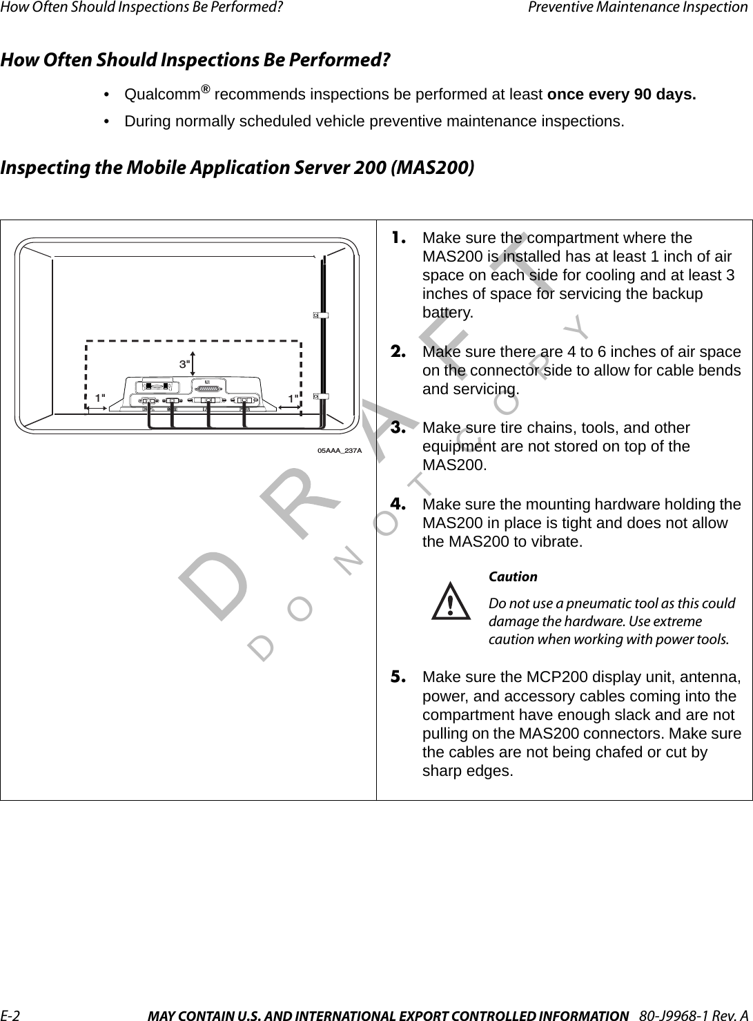
Ezurio Ltd Wireless Interface Box 80 J9968 1 A
UserManual.wiki
>
Ezurio
>
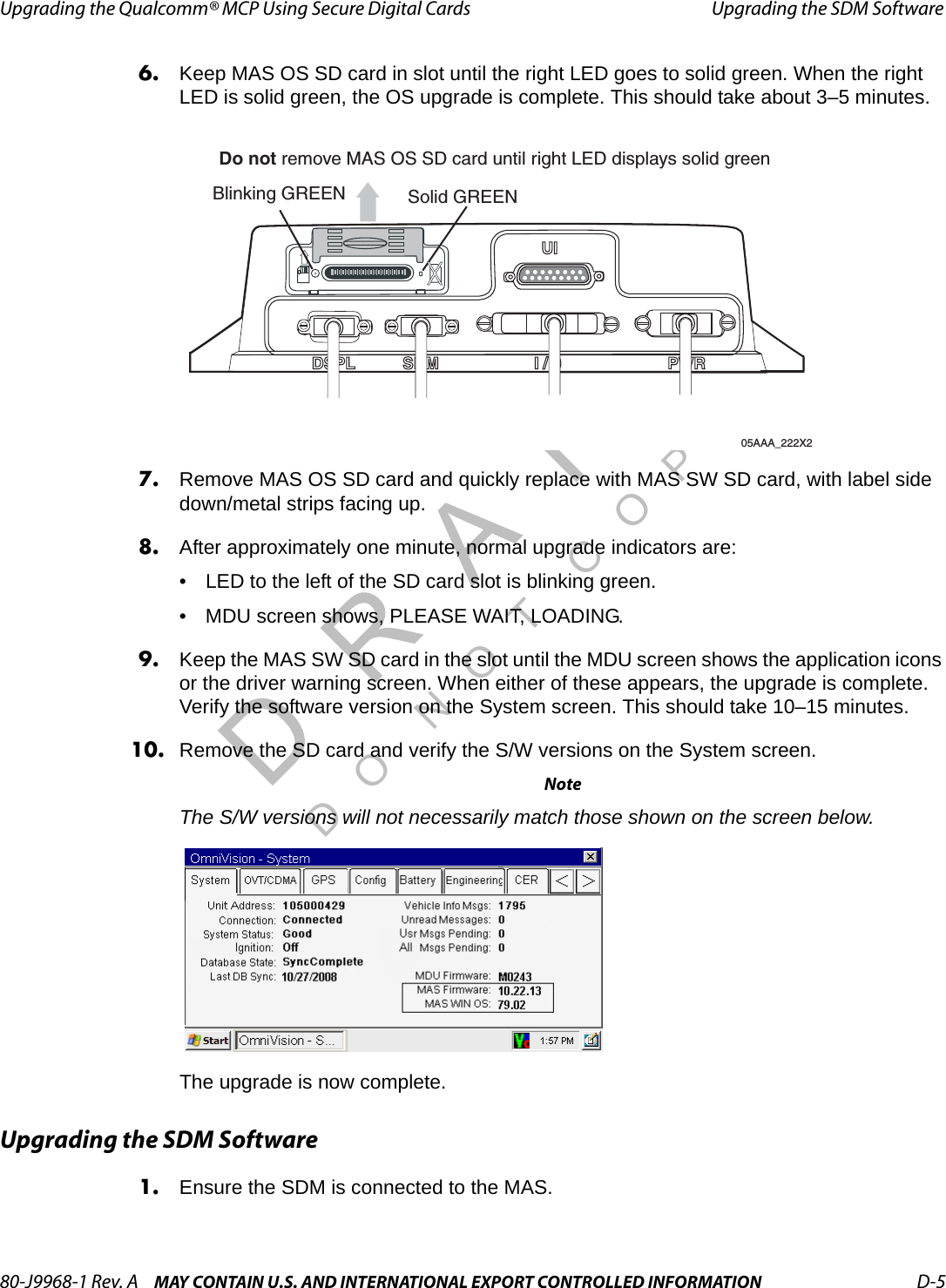
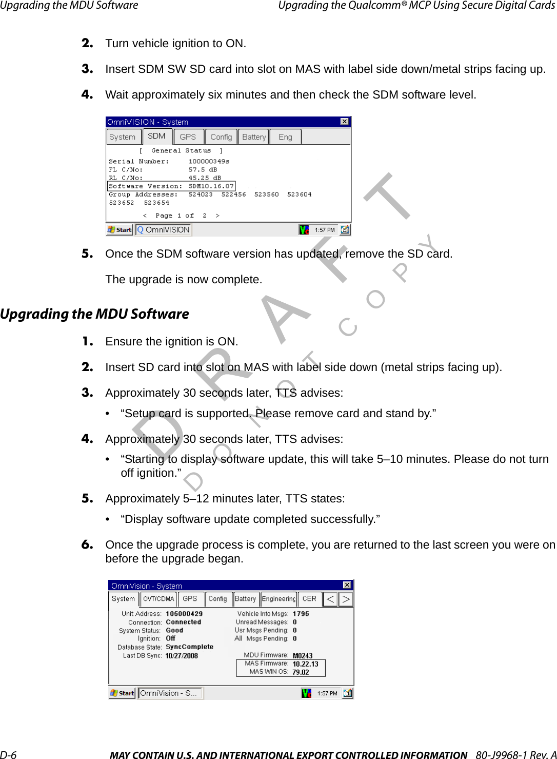
QCWIB User Manual
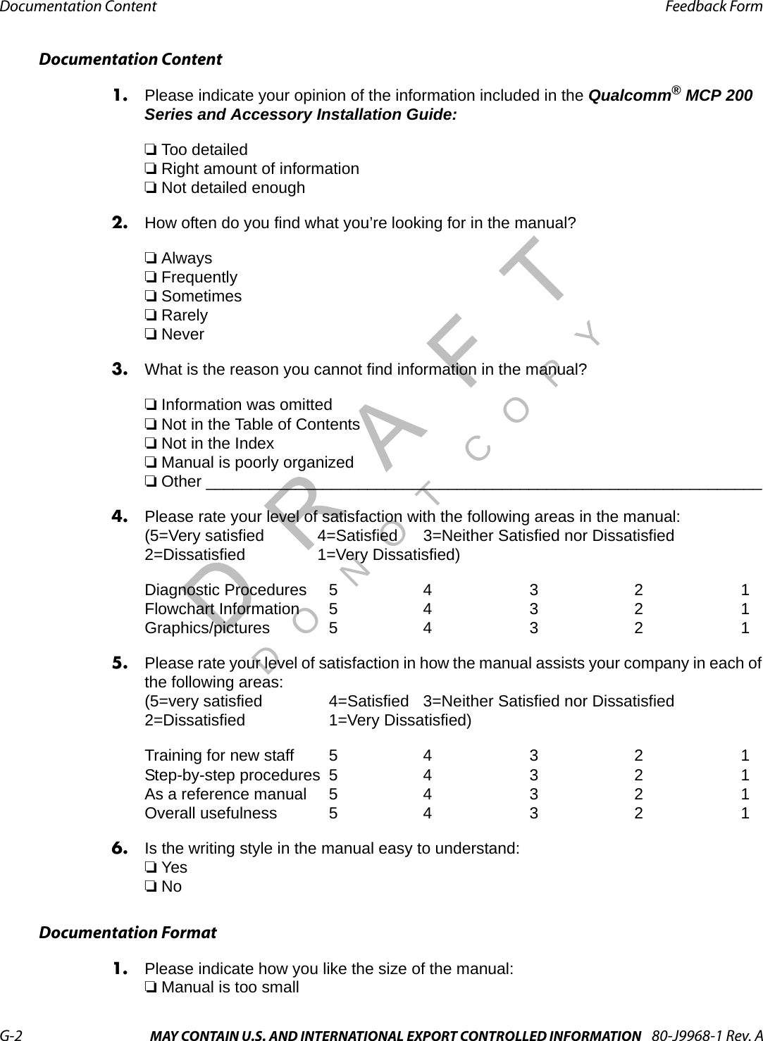
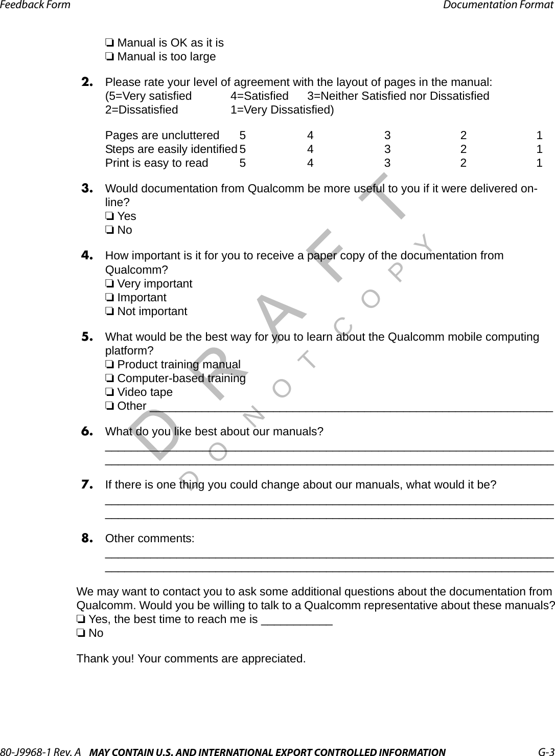
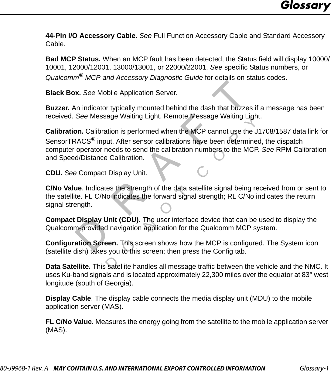
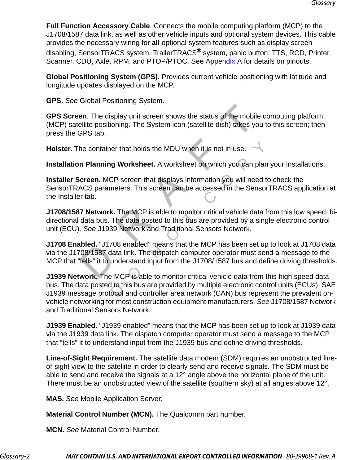
Users Manual
Navigation menu
Upload a User Manual
Namespaces
Wiki Guide
HTML
PDF
Info
Views
User Manual
Discussion / Help
Navigation