Ezurio QCWIB Wireless Interface Box User Manual 80 J9968 1 A
Ezurio Ltd Wireless Interface Box 80 J9968 1 A
Ezurio >
Users Manual

QUALCOMM
Incorporated
5775 Morehouse Drive,
San Diego, California 92121-1714 US
200 Series and Accessory Installation Guide
Qualcomm Mobile Computing Platform
80-J9968-1 Rev. A
Month 2009
QUALCOMM Incorporated
5775 Morehouse Drive
San Diego, CA 92121-1714
U.S.A.
Copyright © 2009 QUALCOMM Incorporated.
All rights reserved.
QUALCOMM, OmniTRACS, OmniExpress, SensorTRACS, QTRACS, GlobalTRACS, and
TrailerTRACS are registered trademarks of QUALCOMM Incorporated in the United States and may be
registered in other countries.
Qualcomm Enterprise Services, QES, T2, MVPc, and TruckMAIL are trademarks of QUALCOMM
Incorporated. QES is a service mark of QUALCOMM Incorporated.
Other product and brand names may be trademarks or registered trademarks of their respective owners.
Qualcomm endeavors to ensure that the information in this document is correct and fairly stated, but
Qualcomm is not liable for any errors or omissions. Published information may not be up to date, and it is
important to confirm current status with Qualcomm.
This technical data may be subject to U.S. and international export, re-export or transfer (export) laws.
Diversion contrary to U.S. and international law is strictly prohibited.
80-J9968-1 Rev. A
Month 2009

80-J9968-1 Rev. A MAY CONTAIN U.S. AND INTERNATIONAL EXPORT CONTROLLED INFORMATION iii
Contents
Important Safety Information
Safety Definitions ................................................................................................ xi
Safety Advice ...................................................................................................... xi
Chapter 1 How the Qualcomm® Mobile Computing Platform 200 Series Works
MCP200 Overview ............................................................................................1-2
Why MCP200 Makes Companies More Efficient ..............................................1-2
MCP200 Component Description .....................................................................1-3
CDMA Wireless Network and PCS ...................................................................1-4
How MCP200 Uses PCS ............................................................................1-4
Optional Data Satellite ......................................................................................1-5
GPS Network ....................................................................................................1-5
How the MCP200 Uses GPS .....................................................................1-5
Wi-Fi® Network .................................................................................................1-5
How the MCP200 Uses Wi-Fi® ..................................................................1-5
What Is MCP200? .............................................................................................1-6
Chapter 2 Component Overview
Equipment Installation ......................................................................................2-2
Wireless Interface Box 200 (WIB200) ...............................................................2-3
Wireless Interface Box (WIB200) Cable .....................................................2-3
Optional Satellite Data Modem (SDM) ..............................................................2-3
Satellite Data Modem (SDM) Cable ...........................................................2-3
Display Interface Unit 200 (DIU200) .................................................................2-4
Display Cable .............................................................................................2-4
Procedures for Using the DIU200 ..............................................................2-4
Mobile Application Server 200 (MAS200) .........................................................2-5
Backup Battery .................................................................................................2-6
Accessory Cable for the Qualcomm® MCP200 .........................................2-6
Speaker Switch Cable ................................................................................2-6
Power Cable ...............................................................................................2-6
Optional Remote Control Device (RCD) ...........................................................2-7
Optional Accessories for the MCP200 ..............................................................2-7

Contents
iv MAY CONTAIN U.S. AND INTERNATIONAL EXPORT CONTROLLED INFORMATION 80-J9968-1 Rev. A
DO NOT COPY
Chapter 3 General Wiring and Installation Guidelines
Making Electrical Connections ......................................................................... 3-2
Approved Qualcomm Electrical Connectors .............................................. 3-2
Wire Stripping ............................................................................................ 3-2
Butt Splicing................................................................................................ 3-3
Crimping ..................................................................................................... 3-4
Ring Terminals ......................................................................................... 3-10
Proper Grounding ........................................................................................... 3-10
General Installation Guidelines ...................................................................... 3-11
Routing and Protecting Cables ...................................................................... 3-11
Chapter 4 Installation Planning
Installation Guidelines ...................................................................................... 4-2
Safety, Reliability, and Accessibility ........................................................... 4-2
Typical Installation Sequence .......................................................................... 4-2
Typical Installation Locations for MCP200 Components .................................. 4-3
Conventional Vehicle Types ...................................................................... 4-4
Straight Truck Vehicle Types (All Makes) .................................................. 4-6
Cabover Engine Vehicle Types (All Makes) .............................................. 4-6
Special Cable Ordering Instructions for Tilt Cabs ...................................... 4-7
Installation Planning Worksheets for the MCP200 Components ..................... 4-8
Tools and Supplies Recommended for Installations ...................................... 4-11
Qualcomm Approved Sealants ................................................................ 4-11
Chapter 5 Mobile Application Server 200 (MAS200) Installation
General Installation Guidelines ........................................................................ 5-2
Installing the Backup Battery into the MAS200 ................................................ 5-2
Installing the MAS200 into the Mounting Surface ............................................ 5-3
Selecting a Mounting Location ................................................................... 5-3
Securing the MAS200 ................................................................................ 5-5
Installing the Power Cable ............................................................................... 5-5
Power Cable Run ....................................................................................... 5-5
Power Cable Routing ................................................................................. 5-5
Low Voltage Disconnects (LVDs) .............................................................. 5-5
Power Cable Wire Connections ................................................................. 5-6
Grounding Guidelines ...................................................................................... 5-7
Installing the Accessory Cable ......................................................................... 5-7
Cable Run .................................................................................................. 5-8
Connecting Cables to the MAS200............................................................. 5-9
Chapter 6 Wireless Interface Box 200 (WIB200) Antenna Installation
General Installation Guidelines ........................................................................ 7-2
Option A—Antenna Installation Using VHB Tape ............................................ 7-2

80-J9968-1 Rev. A MAY CONTAIN U.S. AND INTERNATIONAL EXPORT CONTROLLED INFORMATION v
Contents
DO N OT
COPY
Antenna Surface Preparation .....................................................................7-2
Option B—Mount Method Installation Using Hardware ....................................7-3
Mount Surface Preparation ........................................................................7-3
Routing the WIB200 Cable ...............................................................................7-4
Connecting the Antenna Cable to the MAS200 ................................................7-4
Chapter 7 Optional Satellite Data Modem (SDM) Installation
General Installation Guidelines .........................................................................8-2
Selecting a Mount .......................................................................................8-2
Orienting the SDM on the Mount ......................................................................8-2
Installing Mounting Bolts ...................................................................................8-3
Line-of-Sight Requirements ..............................................................................8-4
Trailer Swing Area ............................................................................................8-5
Installing the SDM Cable ..................................................................................8-5
Connecting the SDM Cable ........................................................................8-5
SDM Cable Run .........................................................................................8-6
SDM Cable Installation ...............................................................................8-6
Connecting the SDM Cable to the MAS200 .....................................................8-7
Chapter 8 Display Interface Unit 200 (DIU200) Installation
General Installation Guidelines .........................................................................9-2
Selecting a Mounting Location ...................................................................9-2
Installing the DIU200 Holster Using Well-nut Fasteners ...................................9-3
Installing the DIU200 Cable ..............................................................................9-4
DIU200 Cable Run .....................................................................................9-4
Connecting the Display Cable to the DIU200 ...................................................9-4
Inserting the DIU200 into the Holster ................................................................9-5
Connecting the Display Cable to the MAS200 ..................................................9-6
Chapter 9 Optional Text-to-Speech (TTS) Installation
General Installation Guidelines .......................................................................10-2
Selecting a Mounting Location .................................................................10-2
Installing the Remote Control Device (RCD) ..................................................10-2
Connecting the RCD to the Accessory Cable ..........................................10-2
Selecting a Speaker ........................................................................................10-3
Speaker Requirements .............................................................................10-3
Choosing a Speaker .................................................................................10-3
Option A—Connecting to an Existing or Shared Speaker ..............................10-4
Connecting Speaker Switch Cable to Accessory Cable ...........................10-5
Option B—Connecting to a Dedicated 8-ohm Speaker ..................................10-6
Chapter 10 Vehicle Data Bus Connections
Vehicle Data Source Overview .......................................................................11-2

Contents
vi MAY CONTAIN U.S. AND INTERNATIONAL EXPORT CONTROLLED INFORMATION 80-J9968-1 Rev. A
DO NOT COPY
J1939 Data Bus ....................................................................................... 11-2
J1708/J1587 Data Bus ............................................................................ 11-2
Traditional Sensors .................................................................................. 11-2
Vehicle Data Source Selection ....................................................................... 11-3
Guidelines for Connecting to the J1939 Data Bus ......................................... 11-3
J1939 Pre-installation Check Out ................................................................... 11-4
Resistance Test (to Verify that J1939 Is Present) ................................... 11-4
Checking the MCP200 Accessory Cable for CAN0 and CAN1 ................ 11-5
Option 1—Connecting J1939 Using CAN 1 (for All After-Market Installations) 11-5
Making the Connection ............................................................................ 11-6
Option 2—Connecting J1939 Using CAN0 (for Most OEM Prewires) ............ 11-8
Making the Connection............................................................................. 11-9
Connecting J1708 /J1587 ............................................................................ 11-10
Verifying Data Source Connectivity .............................................................. 11-11
Chapter 11 System Verification
What Is Basic Qualcomm® MCP200 System Verification? ........................... 12-2
MCP200 Display Unit Screens ....................................................................... 12-2
MCP200 System Screen ......................................................................... 12-3
MCP200 OVT/CDMA Screens ................................................................. 12-4
MCP200 SDM Screens ............................................................................ 12-5
MCP200 GPS Screen .............................................................................. 12-6
MCP200 Config Screen ........................................................................... 12-7
MCP200 Engineering Screen .................................................................. 12-8
MCP200 CER Screen .............................................................................. 12-8
VDS (Status) Screen ............................................................................... 12-9
Flowchart—Basic MCP200 System Verification .......................................... 12-11
Basic MCP System Verification Procedure .................................................. 12-13
Qualcomm® MCP System Verification Form ............................................... 12-18
Chapter 12 SensorTRACS® Performance Monitoring Verification
SensorTRACS® System Overview ................................................................ 13-2
Performing SensorTRACS® System Verification ........................................... 13-2
Conducting a Road Test .......................................................................... 13-2
SensorTRACS® System Display Screens ..................................................... 13-3
Accessing the SensorTRACS® Screens ................................................. 13-3
Summary Screen...................................................................................... 13-4
Performance Screen................................................................................. 13-5
Parameters Screen................................................................................... 13-6
Odometer Screen .................................................................................... 13-7
PTO Screen.............................................................................................. 13-8
Installer Screen ........................................................................................ 13-9
Special Alert Display Messages ................................................................... 13-12
Warning Messages ................................................................................ 13-12

80-J9968-1 Rev. A MAY CONTAIN U.S. AND INTERNATIONAL EXPORT CONTROLLED INFORMATION vii
Contents
DO N OT
COPY
Power Take-off (PTO) Overview ...................................................................13-12
PTOP (Power Take-off Pump)/PTOC (Power Take-off Compressor).....13-13
PTO Data Input Verification Procedure ........................................................13-14
Chapter 13 Vehicle Maintenance Installation
Vehicle Maintenance Overview ......................................................................14-2
Feature Requirements ..............................................................................14-2
Connecting the J1939 Wires ...........................................................................14-3
Enabling a Vehicle for Vehicle Maintenance ..................................................14-3
Vehicle Maintenance System Verification .......................................................14-4
Chapter 14 TrailerTRACS® System Installation
TrailerTRACS® System Overview ..................................................................15-2
Hardware Requirements ..........................................................................15-2
TrailerTRACS® System Wiring for the Truck .................................................15-2
Fuse Kit Installation ..................................................................................15-2
TrailerTRACS® System Verification ...............................................................15-3
Enabling the Option for the TrailerTRACS® System ...............................15-3
Trailer Connection/Disconnection ............................................................15-4
TrailerTRACS® Diagnostic Screen ..........................................................15-5
Refrigeration Status Screen .....................................................................15-6
Chapter 15 Buzzer Installation
Buzzer Overview .............................................................................................17-1
Mounting Location ..........................................................................................17-2
Installation Guidelines .....................................................................................17-2
Installation Verification ....................................................................................17-2
Chapter 16 Remote Message Waiting Light (RMWL) Installation
RMWL Overview .............................................................................................18-1
Installing the Remote Message Waiting Light .................................................18-2
Installation Verification ....................................................................................18-2
Chapter 17 Wired Panic Button Installation
Wired Panic Button Overview .........................................................................19-1
Installing the Panic Button ..............................................................................19-2
Installation Verification ....................................................................................19-4
Automated Panic Button Test System Dial-in Procedure .........................19-4
Chapter 18 In-Cab Printer Installation
Wiring Configuration .......................................................................................20-2

Contents
viii MAY CONTAIN U.S. AND INTERNATIONAL EXPORT CONTROLLED INFORMATION 80-J9968-1 Rev. A
DO NOT COPY
Installation Guidelines .................................................................................... 20-2
Location ................................................................................................... 20-2
Cables ...................................................................................................... 20-2
Mounting Bracket ........................................................................................... 20-2
Installing the Printer ....................................................................................... 20-3
Installation Verification ................................................................................... 20-4
Return Material Authorization (RMA) Process ............................................... 20-4
O’Neil Printer Parts List .................................................................................. 20-4
Chapter 19 In-Cab Scanner Installation
Installation Guidelines .................................................................................... 21-2
Location ................................................................................................... 21-2
Scanner Cable ......................................................................................... 21-2
Mounting the Scanner .................................................................................... 21-2
Scanner Mounting Option ........................................................................ 21-2
Holster Mounting Option .......................................................................... 21-2
Installing the Scanner ..................................................................................... 21-3
Calibrating the Scanner .................................................................................. 21-3
Sending a Scan .............................................................................................. 21-4
Cleaning the Scanner ..................................................................................... 21-5
Return Material Authorization (RMA) Process ............................................... 21-5
BCS Solutions Scanner Parts List .................................................................. 21-6
Appendix A Wiring Diagrams and Charts
Qualcomm® MCP200 Electrical Diagram ........................................................A-2
Qualcomm® MCP200 Wiring Diagram ............................................................A-3
Power Cable Pin Callouts ................................................................................A-4
Optional Satellite Data Modem (SDM) Cable 9-Pin Connector Callouts ..........A-5
Primary Accessory Cable Pin Callouts .............................................................A-6
Secondary Accessory Cable Pin Callouts ........................................................A-7
Display Interface Unit 200 (DIU200) Connector Pin Callouts ...........................A-8
Six-pin Data Link Connector Pin Callouts ........................................................A-9
Nine-pin Data Link Connector Pin Callouts ....................................................A-10
Radio Connector Pin Callouts ........................................................................A-11
CAN Conductor Cable ....................................................................................A-12
Appendix B Environmental and Power Requirements
MCP200 Environmental and Power Requirements ..........................................B-2
Appendix C Standard RMA Procedure
The Return Material Authorization Process .....................................................C-1
How to Obtain an RMA Number .......................................................................C-2
Required Information .................................................................................C-2

80-J9968-1 Rev. A MAY CONTAIN U.S. AND INTERNATIONAL EXPORT CONTROLLED INFORMATION ix
Contents
DO N OT
COPY
Creating an RMA On-line ...........................................................................C-4
RMA Policies ...................................................................................................C-4
What to Return/Not Return ........................................................................C-4
Where to Return Equipment ......................................................................C-5
“Past Due” Equipment ...............................................................................C-6
Customer-Damaged Equipment ................................................................C-6
Missing, Lost, Stolen, or Destroyed Equipment ........................................C-6
Permanent Fleet Size Reduction Request Form .......................................C-7
Appendix D Upgrading the Qualcomm® MCP Using Secure Digital Cards
Checking the Software Versions Installed .......................................................D-2
SD Card Instructions ........................................................................................D-3
Upgrading Only the MAS Software ..................................................................D-3
Upgrading the MAS Operating System and MAS Software .............................D-4
Upgrading the SDM Software ..........................................................................D-5
Upgrading the MDU Software ..........................................................................D-6
Appendix E Preventive Maintenance Inspection
How Often Should Inspections Be Performed? ............................................... E-2
Inspecting the Mobile Application Server 200 (MAS200) ................................ E-2
Inspecting the Display Interface Unit 200 (DIU200) ......................................... E-4
Inspecting the Wireless Interface Box 200 (WIB200) and the Optional Satellite Data Modem
(SDM) .............................................................................................................. E-6
Verifying TrailerTRACS® System Connections ............................................... E-9
Appendix F Component and Document Information
DCNs for Documents Referenced in this Guide .............................................. F-2
MCP200 System Component MCNs Referenced in this Guide ....................... F-2
MCNs for Sealants and Lubricants Referenced in this Guide ......................... F-6
MCN for Qualcomm-recommended Torque Wrench Referenced in this Guide F-6
Appendix G Feedback Form
Feedback Form ................................................................................................G-1
Company Information ................................................................................G-1
Documentation Content .............................................................................G-2
Documentation Format ..............................................................................G-2
Glossary
Index

Contents
xMAY CONTAIN U.S. AND INTERNATIONAL EXPORT CONTROLLED INFORMATION 80-J9968-1 Rev. A
DO NOT COPY

80-J9968-1 Rev. A MAY CONTAIN U.S. AND INTERNATIONAL EXPORT CONTROLLED INFORMATION xi
DO NOT COPY
Important Safety Information
Safety Definitions
The following Caution and Warning definitions are intended to advise the driver when it is
safe to use a display unit.
CAUTION indicates a potentially hazardous situation which, if not avoided, may result in
minor or moderate injury. It may also be used to alert against unsafe practices.
WARNING indicates a potentially hazardous situation which, if not avoided, could result in
death or serious injury.
Safety Advice
The following Safety Advice is provided for drivers, installers, and application developers who
use and/or locate all types of display units.
If you are a Driver, do not use a display unit when the vehicle is in motion.
If you are an Installer, do not locate the display unit, including third-party devices, where it
obstructs the driver’s field of vision, distracts the driver from the driving task, or interferes with
the driver’s operation of controls or displays. The following label is to be posted in clear view
for the driver to see.
If you are a Third-party Device Manufacturer or Application Developer, it is your
responsibility to provide appropriate warnings regarding the safe use of your device(s) in
conjunction with Qualcomm® equipment. Applications should not require the driver to divert
his attention from the road while driving a vehicle.

Safety Advice Important Safety Information
xii MAY CONTAIN U.S. AND INTERNATIONAL EXPORT CONTROLLED INFORMATION 80-J9968-1 Rev. A
DO NOT COPY
FCC notice:
Caution: Any changes or modifications to this device not explicitly approved by
manufacturer could void your authority to operate this equipment.
This equipment complies with FCC radiation exposure limits set forth for an
uncontrolled environment. This equipment should be installed and operated with
minimum 20 cm between the radiator and your body. This transmitter must not be
collocated or operating in conjunction with any other antenna or transmitter unless
authorized to do so by the FCC.
IC Notice:
The device’s user manual does not contain the following or equivalent statement as
per RSS-GEN section 7.1.5: Operation of this device is subject to the following two
conditions: (1) this device may not cause interference, and (2) this device must
accept any interference, including interference that may cause undesired operation
of the device.

80-J9968-1 Rev. A MAY CONTAIN U.S. AND INTERNATIONAL EXPORT CONTROLLED INFORMATION 1-1
DO NOT COPY
1
How the Qualcomm® Mobile Computing Platform 200 Series Works
Topics in this chapter provide a basic overview of the MCP 200 Series and how its
components interact to deliver effective, two-way communications and other value-added
services.
MCP200 Overview. . . . . . . . . . . . . . . . . . . . . . . . . . . . . . . . . . . . . . . . . . . . . . . . . . 1-2
Why MCP200 Makes Companies More Efficient . . . . . . . . . . . . . . . . . . . . . . . . . . . 1-2
MCP200 Component Description. . . . . . . . . . . . . . . . . . . . . . . . . . . . . . . . . . . . . . . 1-3
CDMA Wireless Network and PCS . . . . . . . . . . . . . . . . . . . . . . . . . . . . . . . . . . . . . 1-4
Optional Data Satellite . . . . . . . . . . . . . . . . . . . . . . . . . . . . . . . . . . . . . . . . . . . . . . . 1-5
GPS Network . . . . . . . . . . . . . . . . . . . . . . . . . . . . . . . . . . . . . . . . . . . . . . . . . . . . . . 1-5
Wi-Fi® Network . . . . . . . . . . . . . . . . . . . . . . . . . . . . . . . . . . . . . . . . . . . . . . . . . . . . 1-5
What Is MCP200? . . . . . . . . . . . . . . . . . . . . . . . . . . . . . . . . . . . . . . . . . . . . . . . . . . 1-6
For technical questions, contact Qualcomm Enterprise Services (QESSM) Customer Support.
Customer Support is staffed 24 hours a day, 365 days a year:
In the United States, call 800-541-7490
In Canada, call 800-863-9191

MCP200 Overview How the Qualcomm® Mobile Computing Platform 200 Series Works
1-2 MAY CONTAIN U.S. AND INTERNATIONAL EXPORT CONTROLLED INFORMATION 80-J9968-1 Rev. A
DO NOT COPY
MCP200 Overview
MCP200 is a high bandwidth mobile computing platform designed to help increase customer
service, reduce operating costs, enhance driver productivity, and ensure vehicle safety.
MCP200 offers multi-mode communications (terrestrial and Wi-Fi® are standard, satellite is
optional); and delivers more processing power on the mobile unit, an increased number of
hardware ports, and a Windows® Embedded Standard operating system.
Data transmitted through the MCP200 is backward compatible and interoperable with the
host, so customers can access information across various Qualcomm platforms, such as
MCP 100 Series, OmniTRACS® Mobile Communications System, OmniExpress® Mobile
Communications System, and Untethered Asset Management Service.
Why MCP200 Makes Companies More Efficient
• Companies can maintain two-way contact with their vehicles and drivers 24 hours a day.
• Dispatchers can send pickup and delivery information directly to drivers, keeping vehicles
on the road.
• Text-to-speech alerts drivers of incoming messages and their importance, so drivers can
choose to immediately listen to messages without pulling off the road.
• Dispatchers know when vehicles are expected to arrive at locations, and can pass that
information on to customers.
• Provides dispatchers with vehicle location and position history information by tracking the
location of each MCP200 using latitude and longitude or distance and direction from
landmarks (usually large towns and cities).
• Drivers can inform the dispatcher of road conditions or problems.
• Optional devices allow monitoring of driver performance, engine diagnostics, trailer
locations, and refrigeration status.
• Decision support software enables customers to optimize assets and inform shippers and
consignees of load status.
• Over-the-air software upgrades allow drivers to remain on the road rather than having to
stop at service centers.
• Display interface unit 200 (DIU200) provides a color graphical display, with a sliding
keyboard that integrates touchscreen functionality, extended temperature range, and
improved clarity for delivering critical information to drivers.
• Hours of service data ensures regulatory compliance.
• On-board navigation application provides truck-specific route mappings.
• International Fuel Tax Agreement (IFTA) simplifies fuel reporting for inter-state operations.
• Helps with safety and accident prevention.
• Optimizes fuel management.
80-J9968-1 Rev. A MAY CONTAIN U.S. AND INTERNATIONAL EXPORT CONTROLLED INFORMATION 1-3
How the Qualcomm® Mobile Computing Platform 200 Series Works MCP200 Component Description
DO N OT
COPY
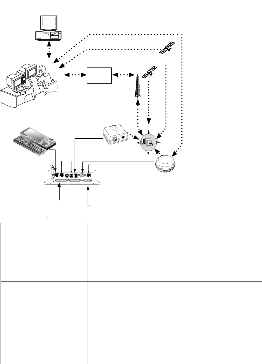
MCP200 Component Description
Component Description
Network Operations Center
(NOC) • Responsible for processing and managing message
traffic between dispatch center and fleet.
• Within the NOC is the Network Management Computer
(NMC), which receives and handles message traffic.
• Located at QUALCOMM Incorporated, in San Diego, CA.
Qualcomm Dispatch
Software (QTRACS®
software)
• Software on the trucking company’s dispatch computer
and dispatcher’s interface with the MCP200.
• Allows dispatcher to send and receive messages, request
MCP200 location information, and perform other dispatch
functions.
• QTRACS/400 and QTRACS/Windows customers
communicate with the NMC via dialup using PPTP or a
frame relay connection.
• QTRACS/Web customers communicate via the NMC
using RI/Web client over a PPTP connection.
SDM
K
w
N
E
S
W
Customer dispatch
computer
Terrestrial
network
MAS200
NOC
Primary
Accessory
cable
Secondary
Accessory
cable
Power/
Ignition
GPS
Satellite
Data
Satellite
DIU200
Shift
Backspace
Ctn Ctn End
Home
lkXZ
lkXZ
Alt
Fn
Symbol
AAA
Up
Pg
Dn
Pg
Shift
Tab
Esc
F1F2 F3 F4 F5 F6 F7 F8 F9 F10 F10 F11F12
Insert Delete
PWR
PWR
IO 1
IO 1
IO 2
IO 2
WIB200
09AAA_01
9
IDD
USB
3G
USB
1/2
LAN

CDMA Wireless Network and PCS How the Qualcomm® Mobile Computing Platform 200 Series Works
1-4 MAY CONTAIN U.S. AND INTERNATIONAL EXPORT CONTROLLED INFORMATION 80-J9968-1 Rev. A
DO NOT COPY
CDMA Wireless Network and PCS
• MCP200 uses CDMA technology to connect dispatchers and vehicles over the wireless
airwaves.
• The Personal Communications Service (PCS) System is a low-powered, higher frequency
competitive technology to cellular, ideal for “in-city” trucking and transport.
• Wherever a terrestrial wireless network exists, drivers can send messages to and receive
messages from dispatchers while traveling.
How MCP200 Uses PCS
• The MCP200 includes the MAS200, which consists primarily of a microprocessor, a
wireless modem module, and data storage.
• The user interface device (DIU200) is the driver’s display terminal that enables the driver
to read, write, and send messages.
• The antenna (located inside the WIB200) relays messages between dispatch and the
driver.
• The antenna receives and transmits wireless information to and from the MAS200.
• The antenna interfaces with local wireless networks. Communication is collected at the
PCS gateway and obtained by Qualcomm’s NOC where it is distributed to the dispatch
center. Dispatchers respond by sending a message back to Qualcomm’s NOC, where it is
relayed to the PCS gateway and broadcast out to the wireless network to be picked up by
the vehicle’s antenna.
Code Division Multiple
Access (CDMA)
Wireless Network
• Radio frequency (RF) signals are received from the
antenna by the MCP200 via the wireless interface box
(WIB200) from a wireless communication network, which
varies depending on geographic location.
Optional Data Satellite • Handles all two-way message traffic between the vehicle
and the NMC if you are using a satellite data modem
(SDM).
GPS Positioning Satellites • Uses 24 satellites to provide vehicle positioning
information.
Mobile Computing Platform
200 (MCP200) • Driver’s interface with the Qualcomm platform and the
component that resides in the vehicle.
• Allows the driver to send and receive messages.

80-J9968-1 Rev. A MAY CONTAIN U.S. AND INTERNATIONAL EXPORT CONTROLLED INFORMATION 1-5
How the Qualcomm® Mobile Computing Platform 200 Series Works Optional Data Satellite
DO N OT
COPY
Optional Data Satellite
• Used if you are using an SDM.
• Located approximately 22,300 miles over the equator at 83° west longitude (south of
Georgia).
• Uses Ku-band signals to handle all two-way message traffic between the vehicle and the
NMC.
• Sends the message along the forward message link to the MCP200.
• Receives the message back from the driver along the return message link.
GPS Network
• A worldwide radio-navigation system formed from a constellation of 24 satellites and their
ground stations.
• Uses satellites as reference points to calculate positions accurate to a matter of meters.
• Allows every square meter of the planet to have a unique address.
• Originally created for and used by the military.
• Currently used in a number of industries, including construction, film, farming, computer,
transportation, telecommunication, and wireless.
• A standard feature of the MCP200.
How the MCP200 Uses GPS
• MCP200 receives positioning data from the GPS receiver, which is integrated inside the
antenna to determine location.
• NOC receives position data from the MCP200 whenever a message is sent to a vehicle
and acknowledged, and whenever a driver sends a message to a dispatcher.
• NOC automatically retrieves position data from the NOC at regular intervals and makes it
available to the dispatcher.
• Dispatcher can request a position report from the MCP200 at any time.
Wi-Fi® Network
• A wireless networking technology that uses radio waves to provide wireless high-speed
internet and network connections.
• Provides Wi-Fi enabled devices, such as PCs, game consoles, mobile phones, MP3
players, and PDAs, access to the internet when within range (“hotspot” area) of a wireless
network.
• Applications and devices that support Wi-Fi are interoperable with one another.
• Based on IEEE 802.11 standards.
How the MCP200 Uses Wi-Fi®

What Is MCP200? How the Qualcomm® Mobile Computing Platform 200 Series Works
1-6 MAY CONTAIN U.S. AND INTERNATIONAL EXPORT CONTROLLED INFORMATION 80-J9968-1 Rev. A
DO NOT COPY
What Is MCP200?
• Mobile part of the Qualcomm platform installed in a customer’s vehicle.
• Provides the driver with the ability to exchange messages with the dispatch center.
• Sends vehicle location information to the NOC.
• Each MCP200 has its own unique unit address which is the serial number on the MAS200.
This address is used by the NMC to route messages to the correct vehicle. The unit
address for a particular vehicle changes if the MAS200 in the vehicle is replaced.
• MCP200 operator, typically the driver, uses the display screens for creating, sending, and
reading messages; system verification; and troubleshooting.
• Standard components:
- Wireless interface box (WIB200)—Contains terrestrial and Wi-Fi® modems, and
antennae that provide CDMA/GSM/UMTS communication.
- Mobile application server (MAS200)—Communication unit which contains the operating
circuitry and memory for the MCP200. The “black box” of the platform.
- Display interface unit (DIU200)—Standard display unit for the MCP200, which the driver
uses to communicate with the dispatcher. Consists of a color graphical display with a
Mobile Application
Server (MAS200)
OPTIONAL
Remote Control
Device (RCD)
OPTIONAL
Satellite Data Modem
(SDM)
Wireless Interface Box
(WIB200)
08AAA_053
Shift
Backspace
Ctn Ctn End
Home
lkXZ
lkXZ
Alt
Fn
Symbol
AAA
Up
Pg
Dn
Pg
Shift
Tab
Esc
F1 F2 F3 F4 F5 F6 F7 F8 F9 F10 F10 F11F12
Insert Delete
(DIU200)
Display Interface Unit
Antenna

80-J9968-1 Rev. A MAY CONTAIN U.S. AND INTERNATIONAL EXPORT CONTROLLED INFORMATION 1-7
How the Qualcomm® Mobile Computing Platform 200 Series Works What Is MCP200?
DO N OT
COPY
sliding keyboard that integrates touchscreen functionality, extended temperature range,
and improved clarity for drivers.
• Optional components:
- Satellite data modem (SDM)—Contains the antenna that communicates with the
satellite and GPS receiver.
- Remote control device (RCD)—Small keypad that allows the driver to safely listen to
incoming messages without having to sop the vehicle and read the message(s) on the
display.

What Is MCP200? How the Qualcomm® Mobile Computing Platform 200 Series Works
1-8 MAY CONTAIN U.S. AND INTERNATIONAL EXPORT CONTROLLED INFORMATION 80-J9968-1 Rev. A
DO NOT COPY

80-J9968-1 Rev. A MAY CONTAIN U.S. AND INTERNATIONAL EXPORT CONTROLLED INFORMATION 2-1
DO NOT COPY
2
Component Overview
Topics in this chapter provide a basic component and wiring overview of the Qualcomm®
mobile computing platform 200 (MCP200) installation.
• For planning and installation instructions, see Chapters 4–11.
• For optional accessory installation, refer to Optional Accessories for the MCP200 on
page 2-7.
Equipment Installation . . . . . . . . . . . . . . . . . . . . . . . . . . . . . . . . . . . . . . . . . . . . . . . 2-2
Wireless Interface Box 200 (WIB200) . . . . . . . . . . . . . . . . . . . . . . . . . . . . . . . . . . . 2-3
Optional Satellite Data Modem (SDM). . . . . . . . . . . . . . . . . . . . . . . . . . . . . . . . . . . 2-3
Display Interface Unit 200 (DIU200) . . . . . . . . . . . . . . . . . . . . . . . . . . . . . . . . . . . . 2-4
Mobile Application Server 200 (MAS200) . . . . . . . . . . . . . . . . . . . . . . . . . . . . . . . . 2-5
Backup Battery. . . . . . . . . . . . . . . . . . . . . . . . . . . . . . . . . . . . . . . . . . . . . . . . . . . . . 2-6
Optional Remote Control Device (RCD) . . . . . . . . . . . . . . . . . . . . . . . . . . . . . . . . . 2-7
Optional Accessories for the MCP200 . . . . . . . . . . . . . . . . . . . . . . . . . . . . . . . . . . . 2-7
For technical questions, contact Qualcomm Enterprise Services (QESSM) Customer Support.
Customer Support is staffed 24 hours a day, 365 days a year:
In the United States, call 800-541-7490
In Canada, call 800-863-9191

Equipment Installation Component Overview
2-2 MAY CONTAIN U.S. AND INTERNATIONAL EXPORT CONTROLLED INFORMATION 80-J9968-1 Rev. A
DO NOT COPY
Equipment Installation
Qualcomm MCP200 masterpack:
• Wireless interface box 200 (WIB200) • Cables
• Display interface unit 200 (DIU200) • Backup battery
• Mobile application server 200 (MAS200)
SDM
SDM Cable
Accessory Connections
(e.g., RMWL, J1708, RCD, TTS)
Power Cable
Accessory Cable
Power Connections
MAS
Display Cable
Remote
Control Device
CB or
Stereo Speaker
Speaker
Cable
Media Display Unit
TMCP_SMCP
Satellite MCP Connection Points
MAS
Display
Typical truck cab - top view
MAS
Antenna
cable
Terrestrial
Antenna
Terrestrial
Antenna
Display
Terrestrial MCP Connection Points
80-J9968-1 Rev. A MAY CONTAIN U.S. AND INTERNATIONAL EXPORT CONTROLLED INFORMATION 2-3
Component Overview Wireless Interface Box 200 (WIB200)
DO N OT
COPY
Wireless Interface Box 200 (WIB200)
The WIB200 includes terrestrial and Wi-Fi® modems, and antennae that provide CDMA/
GSM/UMTS communication. The hardware provides reliable communication and GPS
positioning.
• Height: 3.4 inches
• Width: 6.5 inches
• Length: 6.5 inches
• Extended operating temperature range:
-30C to +70 C / -22F to +158F
• 802.11 compatible
• Lightweight housing for easy installation.
• Rugged design
Wireless Interface Box (WIB200) Cable
• Connects the WIB200 to the MAS200.
• Standard length is two feet.
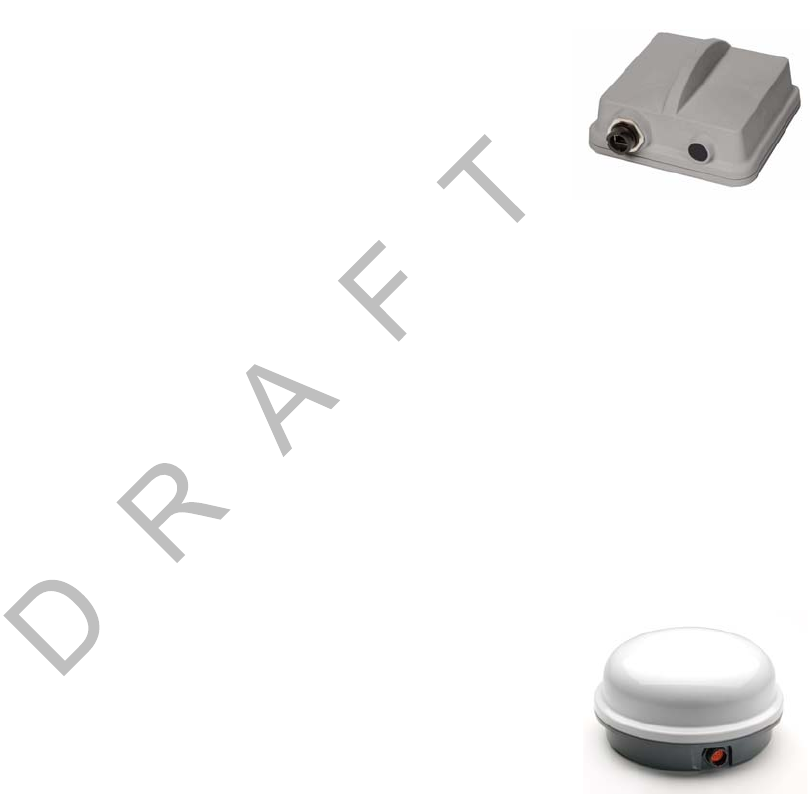
Optional Satellite Data Modem (SDM)
The SDM communicates bi-directionally via an antenna to a geostationary satellite. The SDM
is lightweight and rugged in design with strengthened antenna housing for protection against
weather and external elements.
• Height: 6.8 inches
• Diameter: 12 inches
• Weight: 7.0 pounds
• Operating temperature range:
-40C to +70C / -40F to +158F
• Connects with one Ku-band satellite for two-way data transmission. A secondary
frequency exists as a backup satellite.
• Robust sealing mechanism for use in all outdoor environments.
• Housing has the same bolt pattern as the OmniTRACS® antenna communication unit
(ACU) for ease of installation.
Satellite Data Modem (SDM) Cable
• Connects the SDM to the MAS200.
• Standard length is 20 feet.

Display Interface Unit 200 (DIU200) Component Overview
2-4 MAY CONTAIN U.S. AND INTERNATIONAL EXPORT CONTROLLED INFORMATION 80-J9968-1 Rev. A
DO NOT COPY
Display Interface Unit 200 (DIU200)
A color graphical display with sliding keyboard that integrates touchscreen functionality,
extended temperature range, and improved clarity for delivering
critical information to drivers.
• Dimensions—Open: 10.4 x 8.5 x 2.0 inches
Dimensions—Closed: 10.4 x 5.3 x 2.0 inches
• Weight: 3.2 pounds
• Screen size: 7-inch diagonal
• Resolution: 800 x 480
• Extended operating temperature range: -30C to +70C / -22F to +158F. Display brightness
is reduced at temperatures above +60C / +140F to reduce internal heat generation.
• Standard QWERTY keyboard with 4 arrow/navigation keys.
• Three indicator LEDs alert drivers of incoming messages, connectivity, and other
information.
• 16:9 aspect ratio color TFT LCD touchscreen includes stylus. Icon- and task- driven to
maximize driver efficiency.
• Holstered dash mount and tethered display allows for use anywhere in the cab.
• Display and keyboard are backlit, allowing the driver to distinguish keys in the dark. An
ambient light sensor adjusts backlight when it gets dark.
• Integrated speaker can be used for audio throughout the cab.
• One standard USB port for peripherals.
• Utilizes in-motion user interface to reduce driver distraction and increase safe driving.
• Touchscreen provides valid Cartesian touch coordinates for the entire active display
surface.
Display Cable
• Connects the DIU200 to the MAS200.
• Standard length is 20 feet: 17 feet of straight cable; 3 feet of coiled cable.
Procedures for Using the DIU200
What to use for navigating the DIU200 touchscreen—PDA stylus (provided) or your
fingers.
What NOT to use for navigating the DIU200 touchscreen—pencils, pens, metal objects, or
any other devices which could possibly scratch the touchscreen.
What to use when cleaning the DIU200—a soft cloth and either plain water, glass cleaner,
or mild soap. Do not spray any liquid directly onto the DIU200.
80-J9968-1 Rev. A MAY CONTAIN U.S. AND INTERNATIONAL EXPORT CONTROLLED INFORMATION 2-5
Component Overview Mobile Application Server 200 (MAS200)
DO N OT
COPY
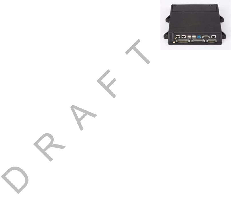
Mobile Application Server 200 (MAS200)
The hardware component that leverages the Windows® Embedded Standard operating
system to deliver computing intelligence, processing power, and
expansion capability.
• Dimensions: 9.7 x 6.5 x 2.4 inches
• Weight: 4.3 pounds
• Extended operating temperature range:
-40C to +70C / -40F to +158F
• Storage temperature range: -40C to +85C / -40F to +185F
• On-board memory: 8 GB of compact flash solid state memory and 1 GB RAM. Optional
16GB flash memory upgrade available.
• Rugged hardware is compliant to SAE xJ1455 vibration profiles.
• .NET framework version 3.5.
• Intel® Extended Temperature Atom 1.3 GHz.
• Backup battery for cold crank condition.
• Supports a wide range of port interfaces that allow connections to on-board equipment:
-J1708 Bus connects to J1708 bus of older trucks.
-(2) J1939/CAN Bus connect to J1939 bus of newer trucks. Can be used to drive some
serial tachographs.
-(4) USB 2.0 Host Ports allow USB peripherals, such as handheld scanners,
keyboards, and storage devices.
-RS-232 Interface allows connectivity to devices, such as printers, barcode readers,
and scanners.
-Configurable Interface (RS-232 or RS-485) connects to modular truck interface
systems.
- Ethernet Port RJ45 Connector
-(2) Display Ports allow for in-dash infotainment system and one other display.
• Supports these other interfaces:
-(7) Power Drivers act as switches to control lights, buzzers, door locks, etc.
-(6) Digital Inputs allow the MAS200 to sense door openings, button pushes, alarm
status, power takeoff (PTO) clutch position, etc.
-(2) Analog Inputs allow the MCP200 to read and react to analog values, such as
temperature, light levels, and humidity levels.
-Panic Button Input allows connection of a panic button for emergency driver
signaling.
-Engine and Vehicle Speed Inputs sense the speed of the engine and the vehicle.

Backup Battery Component Overview
2-6 MAY CONTAIN U.S. AND INTERNATIONAL EXPORT CONTROLLED INFORMATION 80-J9968-1 Rev. A
DO NOT COPY
-(2) Tamper Detect Lines detect tampering with the SDM and WIB200.
-Decoy Tamper Detect Line detects tampering with decoy vehicle wiring.
-Indicator Box Output drives a warning lamp to alert drivers of overspeed or overrev.
-Tethered Asset Management Receiver allows the MAS200 to determine what trailer
is attached to the tractor.
-Audio Output drives a truck’s speakers which allow for voice navigation and
messaging prompts, i.e., text-to-speech.
Backup Battery
• Qualcomm MCP200 requires a rechargeable lead-acid
battery installed into the MAS200.
• For more specific information about the backup battery,
see Chapter 5.
• When vehicle power is lost to the MCP200, the backup battery allows the MAS200 to shut
down gracefully and properly store data. Without a healthy battery installed, there is a high
probability of experiencing data loss or corruption.
Accessory Cable for the Qualcomm® MCP200
• Connects accessories and options, such as the SensorTRACS system®, the
TrailerTRACS system, and the RCD and speaker to the MAS200 for text-to-speech (TTS)
play.
• Standard length is 20 feet.
• Does not support wiring for the CDU, Axle, RPM, PTOP, or PTOC.
Speaker Switch Cable
• Connects a vehicle into a speaker to play text-to-speech.
• Cable length is 8 feet.
• Do not need if a dedicated speaker is added to the vehicle for text-to-speech (TTS).
Power Cable
• Connects the +12/24 VDC unswitched power source (battery), the +12/24 VDC switched
power (ignition), and the system ground to the MAS200.
• Standard length is 20 feet.
Pull Tab
Battery Pack
80-J9968-1 Rev. A MAY CONTAIN U.S. AND INTERNATIONAL EXPORT CONTROLLED INFORMATION 2-7
Component Overview Optional Remote Control Device (RCD)
DO N OT
COPY
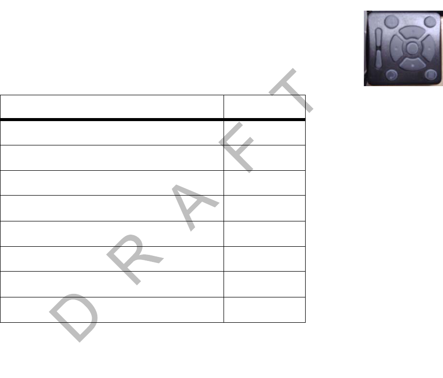
Optional Remote Control Device (RCD)
An easily accessible in-cab device allowing drivers to easily manage message playback and
the text-to-speech (TTS) feature.
• Extended operating temperature range: -30C to +70C.
• Storage temperature range: -40C to +85C.
• Small and easy to mount to the vehicle dash.
Optional Accessories for the MCP200
Accessory Chapter
SensorTRACS system 13
Vehicle Maintenance 14
TrailerTRACS system 15
Buzzer 17
Remote message waiting light 18
Panic button 19
Printer 20
Scanner 21

Optional Accessories for the MCP200 Component Overview
2-8 MAY CONTAIN U.S. AND INTERNATIONAL EXPORT CONTROLLED INFORMATION 80-J9968-1 Rev. A
DO NOT COPY

80-J9968-1 Rev. A MAY CONTAIN U.S. AND INTERNATIONAL EXPORT CONTROLLED INFORMATION 3-1
DO NOT COPY
3
General Wiring and Installation Guidelines
Topics in this chapter provide the Qualcomm-approved general methods for making
connections to cables and wires and the proper connectors to use to avoid potential
problems.
Making Electrical Connections. . . . . . . . . . . . . . . . . . . . . . . . . . . . . . . . . . . . . . . . . 3-2
Proper Grounding. . . . . . . . . . . . . . . . . . . . . . . . . . . . . . . . . . . . . . . . . . . . . . . . . . 3-10
General Installation Guidelines . . . . . . . . . . . . . . . . . . . . . . . . . . . . . . . . . . . . . . . 3-11
Routing and Protecting Cables . . . . . . . . . . . . . . . . . . . . . . . . . . . . . . . . . . . . . . . 3-11
If you have technical questions while reviewing this chapter, please contact Qualcomm
Enterprise Services (QESSM) Customer Support. Customer Support is staffed 24 hours a day,
365 days a year:
In the United States, call 800-541-7490
In Canada, call 800-863-9191
Making Electrical Connections General Wiring and Installation Guidelines
3-2 MAY CONTAIN U.S. AND INTERNATIONAL EXPORT CONTROLLED INFORMATION 80-J9968-1 Rev. A
DO NOT COPY
Making Electrical Connections
Approved Qualcomm Electrical Connectors
The only Qualcomm-approved electrical connectors are crimp butt splices and crimp ring
terminals. Qualcomm recommends Nylon insulated, seamless butt connectors with
inspection windows. Heat-shrinkable butt connectors are preferred. When butt splicing
multiple wires on one end of a butt splice and a different number of wires on the other end,
step-down butt splices are recommended.
WARNING
Not following proper wiring guidelines and using improper crimps and butt splices
may cause intermittent connections and may result in unexpected truck down time or
system failure.
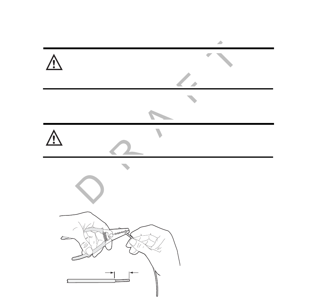
Wire Stripping
Caution
Use care in stripping wires. Vibration can cause nicked wires to fail. Using wire
cutters, knives, or other tools can damage the conductor wire and/or insulation.
Knowing and following proper wire stripping techniques is essential for performing successful
and safe electrical connections of all system components.
1. Using a wire stripper, strip approximately 1/4" off the end of an insulated wire.
2. After stripping the wire, verify that the wire is not severed, nicked, or damaged by the
stripping tool. If the wire has been properly stripped, it is ready to be butt spliced. If the
wire has been damaged, restrip the wire (see step 1.).
1/4"
approx.
Strip
03AAA_270a
80-J9968-1 Rev. A MAY CONTAIN U.S. AND INTERNATIONAL EXPORT CONTROLLED INFORMATION 3-3
General Wiring and Installation Guidelines Butt Splicing
DO N OT
COPY
Butt Splicing
• Qualcomm recommends Nylon insulated, seamless butt connectors with inspection
windows.
• Heat-shrinkable butt connectors are preferred.
Butt splicing can be done inside and outside the cab or enclosure. See Butt Splicing
Connections Done Inside the Vehicle (Out of the Weather) on page 3-3 and Moisture
Protection for Connections Done Outside the Vehicle on page 3-7.
Make sure the size of the butt splice is appropriate for the job. A good butt splice has these
characteristics:
• The ends of the bare wires are visible through an inspection window.
• The ends of the wires “butt” up against the stop.
• The wires are not exposed beyond splice shielding.
• Crimping does not sever or damage the wires or insulation.
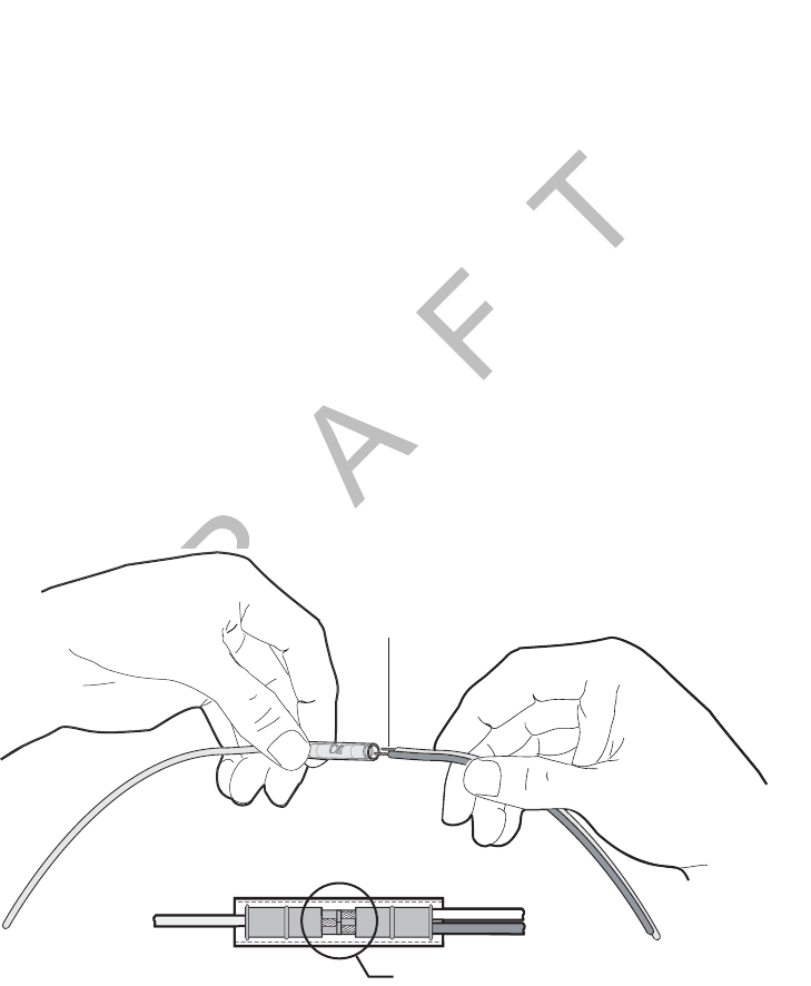
Butt Splicing Connections Done Inside the Vehicle (Out of the Weather)
1. Insert the stripped wires approximately half way into a butt splice, preferably one with
an inspection window for verifying the wire is in the correct position.
2. Repeat this process for the wire on the opposite end of the butt splice. Once a proper
butt splice is confirmed, it is important to properly crimp the butt splice to hold the
connection.
Push the stripped
wires to the inspection window
of the butt splice
03AAA_272
Butt splice
Inspection window
Crimping General Wiring and Installation Guidelines
3-4 MAY CONTAIN U.S. AND INTERNATIONAL EXPORT CONTROLLED INFORMATION 80-J9968-1 Rev. A
DO NOT COPY
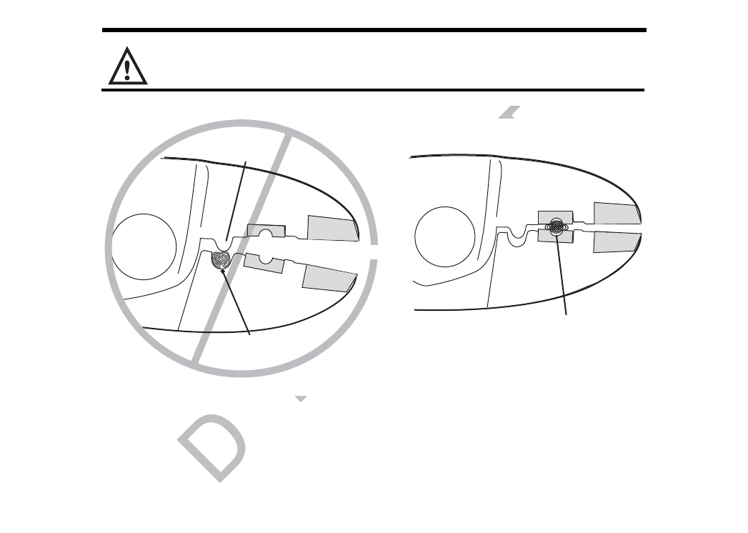
Crimping
• When crimping a butt-spliced wire or cable, be sure the insulated butt splice is crimped
using the insulated position on the crimp tool and not the crimping “tooth” of the tool.
• Crimping butt splices incorrectly can result in a severed wire and a failed wire connection.
Caution
DO NOT crimp on the crimp “tooth.”
1. Using a crimping tool, crimp the butt splice one end at a time. First, crimp the inside
crimp area where the wire has been stripped. Apply necessary pressure to this inside
area.
03AAA_90b
Crimp tooth
INSUL
Do NOT crimp wire here
Crimp here
INSUL
UNINSUL
UNINSUL
80-J9968-1 Rev. A MAY CONTAIN U.S. AND INTERNATIONAL EXPORT CONTROLLED INFORMATION 3-5
General Wiring and Installation Guidelines Crimping
DO N OT
COPY
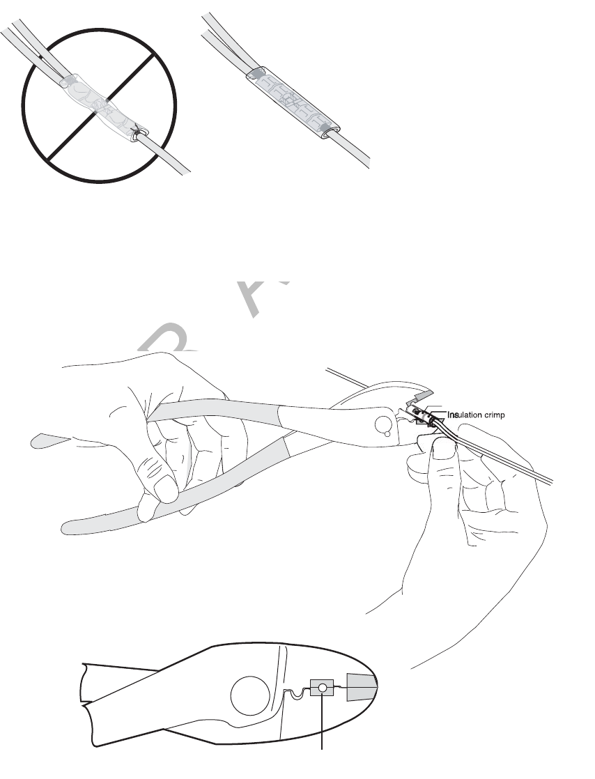
Note
The objective is to apply only the necessary pressure to crimp the butt splice closed and hold
the wire connections together. Do not apply so much pressure as to crush the butt splice and
sever the wire or the insulation on the wire.
2. After crimping the inside of both ends of the butt splice on the “insulated” area of the
crimping tool, next crimp the outside of both ends of the butt splice.
WRONG
Butt splice is visibly crushed,
possibly damaging the wire
and the wire connection.
Some wires are exposed.
CORRECT
Crimping is done properly,
protecting the wire and
the wire connection.
No exposed wires.
03AAA_277A
03AAA_271
Crimp here
Crimping Tool
INSUL
UNINSUL
Wire crim
p
Crimping General Wiring and Installation Guidelines
3-6 MAY CONTAIN U.S. AND INTERNATIONAL EXPORT CONTROLLED INFORMATION 80-J9968-1 Rev. A
DO NOT COPY
3. Verify that the crimps are good and the wires have not been damaged.
4. Do a pull test. Pull on both ends of the wires to ensure a solid butt-spliced connection
exists. The crimped butt splice securely grips the insulated wires.
WARNING
If using heat shrinkable crimps, DO NOT use a heat gun or open flame near
combustible materials. Use a heat gun only when it is safe and appropriate to do so.
Protect surrounding wiring and other components when using a heat gun.
Crimping locations
Inside crimp (stripped wire)
Outside crimp (insulated wire)
03AAA_273
Outside crimp (insulated wire)
Inside crimp (stripped wire)
03AAA_282
80-J9968-1 Rev. A MAY CONTAIN U.S. AND INTERNATIONAL EXPORT CONTROLLED INFORMATION 3-7
General Wiring and Installation Guidelines Crimping
DO N OT
COPY
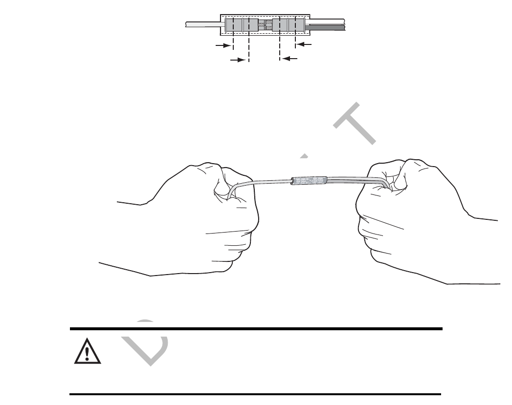
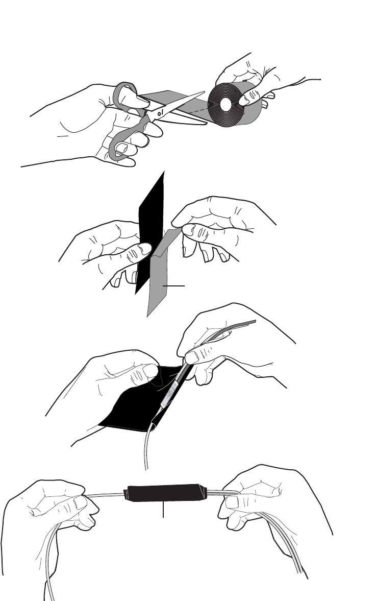
Moisture Protection for Connections Done Outside the Vehicle
1. For crimps done outside the vehicle, when the crimps are verified to be good, use
plastic seal tape to wrap the entire connection. Use a minimum of two layers of seal
tape to completely wrap the connection.
• 3M industrial tape (tape sealant, vinyl/rubber mastic) is available in a 10’ roll from
Qualcomm (MCN# 800-01788-0168). To find a local or nationwide supplier, visit
http://www.3m.com (Mastic, Scotch® Vinyl).
04AAA_22a
Wrap two
layers minimum
Peel Paper
Backing Off
Crimping General Wiring and Installation Guidelines
3-8 MAY CONTAIN U.S. AND INTERNATIONAL EXPORT CONTROLLED INFORMATION 80-J9968-1 Rev. A
DO NOT COPY
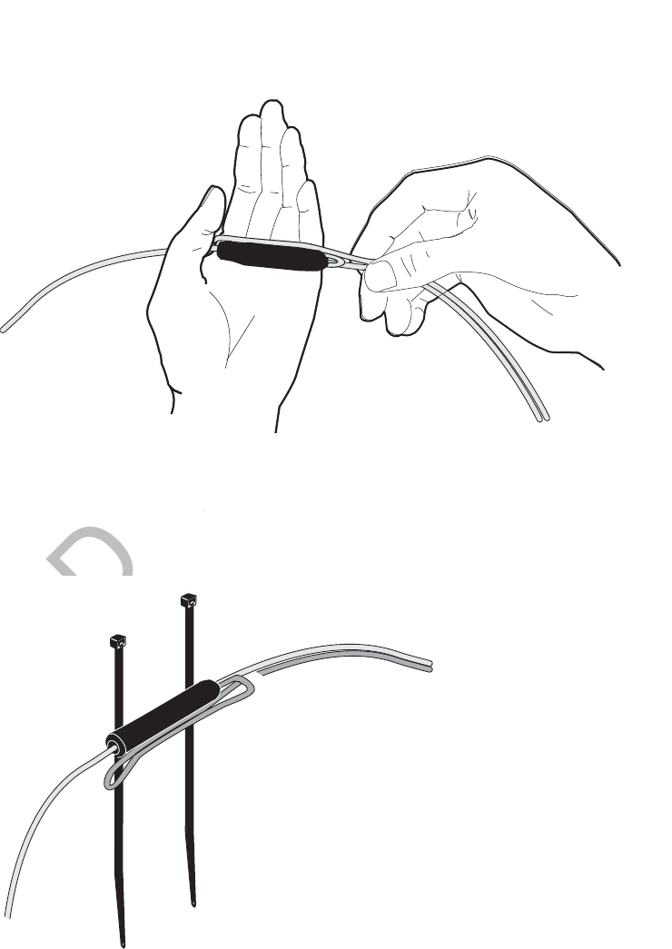
Strain Relief With or Without Weather Protection Tape
If there is sufficient wire available for the Four-Finger Wrap Method:
1. Wrap a wire around four fingers of a hand, one full loop, so that the wire loop is longer
than the wrapped butt splice.
2. Pinch the loop tightly and center it against the wrapped butt splice.
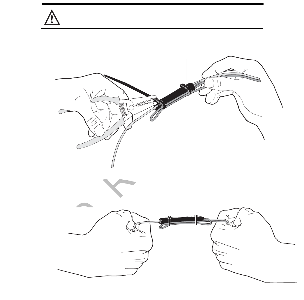
3. Secure the wires together and place 4" tie wraps at the outside ends of the butt splice.
4. Cinch the tie wraps tight and cut them flush to the lock head.
04AAA_24a
Place tie wraps
at outside ends of
butt splice.
04AAA_23a
80-J9968-1 Rev. A MAY CONTAIN U.S. AND INTERNATIONAL EXPORT CONTROLLED INFORMATION 3-9
General Wiring and Installation Guidelines Crimping
DO N OT
COPY
Caution
Failure to cut the tie wraps flush to the lock head can result in minor injury.
5. Firmly tug on the butt-spliced wire connection to make sure the tie wraps do not pull
loose.
If there is NOT sufficient wire available for the Four-Finger Wrap Method:
1. Securely tie wrap the butt spliced wires to existing wires or harnesses in the nearby
vicinity.
Note
It is good practice to tie wrap the newly installed wires to existing wires approximately
every 15"–18".
04AAA_25a
Cut tie wrap
flush with lock head.
04AAA_26
a
Ring Terminals General Wiring and Installation Guidelines
3-10 MAY CONTAIN U.S. AND INTERNATIONAL EXPORT CONTROLLED INFORMATION 80-J9968-1 Rev. A
DO NOT COPY
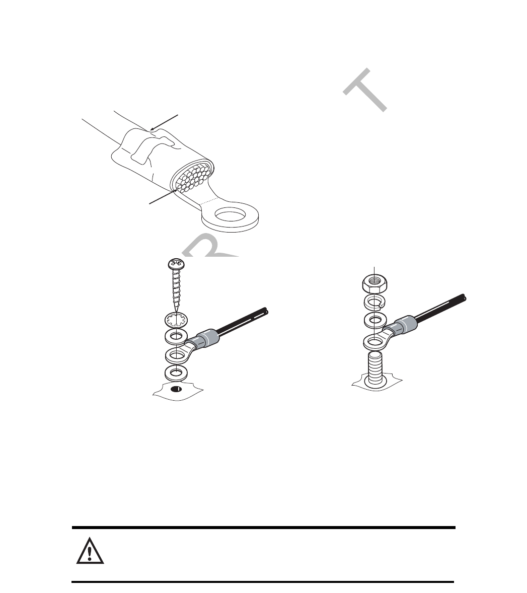
Ring Terminals
When making electrical connections, crimp ring terminals onto the ends of the wires to ensure
good contacts. A properly crimped ring terminal has these characteristics:
• The barrel crimping indent is well-formed and properly positioned.
• The insulated wire’s grip impression is well-formed and provides proper support without
crushing the insulation.
• The wire does not move independently of the lug. Firmly tug on the ring terminal to ensure
it does not pull loose.
• The end of the bare wire protrudes through the crimp barrel approximately 0.03 to 0.125"
depending on the lug size and crimp tool.
Install the ring terminal on the ground connection using one of the following options:
Proper Grounding
When establishing a good chassis ground, avoid areas that may be potentially isolated from
ground by a hinge or bad welds. It is extremely important that you create clean, secure, tight,
metal-to-metal grounds. If grounding terminals are not available, remove the paint from the
surface of the metal connected to the chassis to make the ground. Make sure the wires are
not strained or vulnerable to damage.
WARNING
Not following proper grounding guidelines may cause intermittent connections and
may result in unexpected truck downtime or system failure.
Wire gripping impression
is well formed
Bare wire
protrudes 0.03 to
0.125 inch
OM/E-0093-97
Flat Washer
Flat Washer
Flat Washer
Star Washer
Lock Washer
Nut
Terminal Connector
Terminal Connector
Terminal
Screw
03AAA 285

80-J9968-1 Rev. A MAY CONTAIN U.S. AND INTERNATIONAL EXPORT CONTROLLED INFORMATION 3-11
General Wiring and Installation Guidelines General Installation Guidelines
DO N OT
COPY
General Installation Guidelines
• Determine the most direct and protected route when routing cables to connect the
components to each other and to the vehicle. Refer to Chapter 4.
• The standard cable length for the power, display, and accessory cables is 20 feet.
- If you are working with a tilt cab, a longer cable may be necessary.
• Do not trim cable lengths to fit a specific vehicle.
• Keep protective caps in place or wrap connector with plastic/electrical tape until you’re
ready to connect the cable to the component.
• Use only wire strippers for stripping wires.
• Use only the appropriate insulated crimping tool for crimping insulated connectors.
• Use existing holes for cable routing whenever possible.
Routing and Protecting Cables
PROTECT THE ENTIRE LENGTH of cabling with convoluted tubing when routing the cable:
• Limit the minimum bend diameter:
- accessory cable to 5.0 inches
- display cable to 1.5 inches
- power cable to 2.5 inches
- antenna cable to 2.5 inches
- SDM cable (optional) to 2.5 inches
• Provide strain relief for all cables
• Use supplied grommets
• Use tie wraps
• Debur any drilled holes
DO NOT route cables:
• Near audio system amplifiers
• Near exhaust pipes and other sources of heat
• Near the brake, clutch, or accelerator pedals, and linkage
• Near foot traffic areas
• Near the windshield wiper mechanism
• Near CB radio wires
• Over sharp edges
• Over moving parts
Bend Diameter

Routing and Protecting Cables General Wiring and Installation Guidelines
3-12 MAY CONTAIN U.S. AND INTERNATIONAL EXPORT CONTROLLED INFORMATION 80-J9968-1 Rev. A
DO NOT COPY
Special Exterior Routing Guidelines
• Always use convoluted tubing to protect the cables. Secure the cables to the vehicle with
tie wraps at approximately 18" intervals.
• Route away from exhaust pipes and moving parts. If an exhaust pipe or moving part must
be crossed, use extra tie wraps and route the cable in such a manner that if the tie wrap
fails, the cable will be caught or rest on a safe part (not hot or moving).
• Seal all external holes for cables with refrigeration/tar tape or silicone sealant to keep
moisture out.
• Route cables with any existing vehicle cables.
Special Interior Routing Guidelines
• Route cables under kick plates or carpets.
• Avoid high foot traffic areas.
• When reinstalling kick plates or carpets, be careful that screws do not penetrate cables.
• Route cables with any existing vehicle cables.
• Use convoluted tubing and refrigeration/tar tape when cables are routed through interior
holes with sharp edges.
Storing Excess Cabling
• Secure excess cabling with tie wraps.
• Stow out of sight.
Service Loops (Drip Loops)
• Provide for all cables.
• Ensure that service loops do not cause any obstruction.
Rear View
Cable tied to existing
boomerang brackets
Convoluted tubing
05AAA_223E
Drip loop
Terrestrial Antenna
Rear View
Cable tied to existing
boomerang brackets
Convoluted tubing
Drip loop
05AAA_223
A
Satellite Data Modem
80-J9968-1 Rev. A MAY CONTAIN U.S. AND INTERNATIONAL EXPORT CONTROLLED INFORMATION 3-13
General Wiring and Installation Guidelines Routing and Protecting Cables
DO N OT
COPY
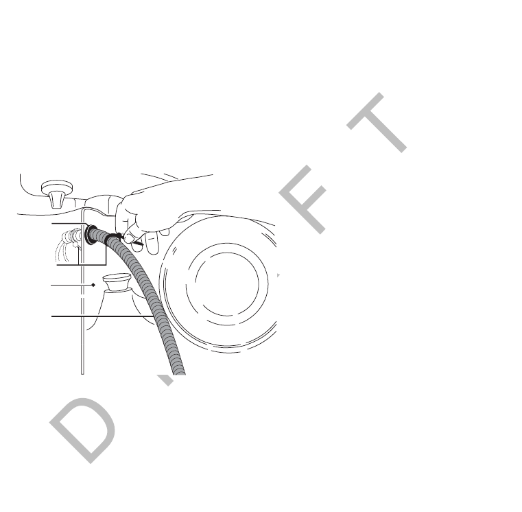
Access Holes
• Use existing holes for cable routing.
• If you drill, drill the smallest hole for the purpose:
- 1-1/2" hole is recommended for cables with a 9-pin DSUB connector, e.g., SDM cable.
- 1" hole is needed for the connectors on the antenna cable.
• Finish holes prior to routing cables:
- Debur holes.
- Use supplied grommet/convoluted tubing with internal holes.
- Extend convoluted tubing beyond the hole.
Fire Wall
of Vehicle
Tie-wraps
Access hole
sealed with
grommet
Convoluted
Tubing
06AAA_89

Routing and Protecting Cables General Wiring and Installation Guidelines
3-14 MAY CONTAIN U.S. AND INTERNATIONAL EXPORT CONTROLLED INFORMATION 80-J9968-1 Rev. A
DO NOT COPY

80-J9968-1 Rev. A MAY CONTAIN U.S. AND INTERNATIONAL EXPORT CONTROLLED INFORMATION 4-1
DO NOT COPY
4
Installation Planning
Topics in this chapter provide guidelines for planning a basic Qualcomm® MCP200
installation.
Installation Guidelines . . . . . . . . . . . . . . . . . . . . . . . . . . . . . . . . . . . . . . . . . . . . . . . 4-2
Typical Installation Sequence. . . . . . . . . . . . . . . . . . . . . . . . . . . . . . . . . . . . . . . . . . 4-2
Typical Installation Locations for MCP200 Components . . . . . . . . . . . . . . . . . . . . . 4-3
Installation Planning Worksheets for the MCP200 Components . . . . . . . . . . . . . . . 4-8
Tools and Supplies Recommended for Installations . . . . . . . . . . . . . . . . . . . . . . . 4-11
For technical questions, contact Qualcomm Enterprise Services (QESSM) Customer Support.
Customer Support is staffed 24 hours a day, 365 days a year:
In the United States, call 800-541-7490
In Canada, call 800-863-9191

Installation Guidelines Installation Planning
4-2 MAY CONTAIN U.S. AND INTERNATIONAL EXPORT CONTROLLED INFORMATION 80-J9968-1 Rev. A
DO NOT COPY
Installation Guidelines
Safety, Reliability, and Accessibility
• Use eye protection when using a drill/performing work that may be hazardous to the eyes.
• Use ear protection in noisy work areas.
• Wear appropriate clothing/uniforms and safety shoes.
• Make sure you know what is behind the area before you drill.
• Use hood safety lanyards when the vehicle hood is open.
• Make sure ladders are in good working order.
• Place ladders in safe positions.
• Install equipment so it will not cause damage to the vehicle or work loose over time.
• Make sure there are no loose components/cables and no unsecured components.
• Use solid mounting surfaces.
• Do not modify or design your own mounts without first obtaining Qualcomm approval
(applies domestically only).
• Mount WIB200 in locations where the unit will receive uninterrupted and undegraded GPS
satellite signals. Refer to Routing the WIB200 Cable on page 7-4.
• Mount optional SDMs in locations where the unit will receive uninterrupted and
undegraded GPS satellite signals. Refer to Line-of-Sight Requirements on page 8-4.
• Install all components in locations where they will not be abused.
• Do not mount antennas on headache racks or exhaust stacks.
• Route all cables away from hot or abrasive areas.
• Ensure that electrical connections are solid and the system ground is a clean, secure,
metal-to-metal chassis ground.
• Choose installation locations where future maintenance can be easily serviced.
• Choose installation locations where components are safe from tampering and damage.
Typical Installation Sequence
1. Determine component installation locations best-suited for your vehicle.
2. Install and route cables.
3. Antenna, see Chapter 7: Wireless Interface Box 200 (WIB200) Antenna Installation or
Chapter 8: Optional Satellite Data Modem (SDM) Installation.
4. Display unit holster and display unit, see Chapter 9.
5. Remote control device (RCD), see Chapter 10.

80-J9968-1 Rev. A MAY CONTAIN U.S. AND INTERNATIONAL EXPORT CONTROLLED INFORMATION 4-3
Installation Planning Typical Installation Locations for MCP200 Components
DO N OT
COPY
6. Accessories.
7. MAS200, see Chapter 5.
8. After you install the MCP200 components, see Chapter 12.
Typical Installation Locations for MCP200 Components
• Securely mount the wireless interface box 200 (WIB200) with a clear “line-of-sight” to the
GPS satellite (see Chapter 7).
• Securely mount the optional satellite data modem (SDM), if being used, to the mounting
assembly with a clear “line-of-sight” to the satellite (see Chapter 8).
• Install the display unit in the cab where it can be easily accessed by the driver.
WARNING
The driver should not use the display unit while the vehicle is in motion.
• Install the MAS200 in a dry, protected space, such as the side box or bunk area.
• Install the optional RCD, if being used, within reach of the driver but where it will not
interfere with the operation of the vehicle.
SDM
SDM Cable
Accessory Connections
(e.g., RMWL, J1708, RCD, TTS)
Power Cable
Accessory Cable
Power Connections
MAS
Display Cable
Remote
Control Device
CB or
Stereo Speaker
Speaker
Cable
Media Display Unit
Scene2A_revised
Conventional Vehicle Types Installation Planning
4-4 MAY CONTAIN U.S. AND INTERNATIONAL EXPORT CONTROLLED INFORMATION 80-J9968-1 Rev. A
DO NOT COPY
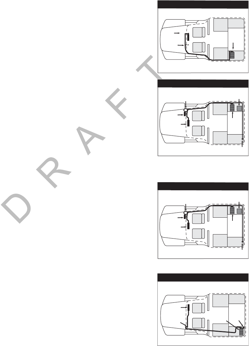
Conventional Vehicle Types
International/Navistar
• MAS200—Install on side wall or hang under bunk.
- Install so there is always SD card slot access.
•DIU200—Install where space allows/customer preference.
• Cables—Route externally or internally.
- Drill a 1" hole for antenna cable.
Freightliner FLD
• MAS200—Install on side wall or hang under bunk.
- Install so there is always SD card slot access.
•DIU200—Attach to electrical access panel behind gearshift.
• Cables—Route externally.
- Cables exit/enter sleeper near MAS200.
- Cables enter/exit cab low on passenger side firewall.
- Drill a 1" hole for antenna cable.
Freightliner Century/Columbia
• MAS200—Install on side wall or hang under bunk.
- Install so there is always SD card slot access.
•DIU200—Install where space allows/customer preference.
• Cables—Route internally.
- Power is at A pillar on passenger side.
- Drill a 1" hole for antenna cable.
Kenworth T600/W900
• MAS200—Install on side wall or hang under the bunk.
- Install so there is always SD card slot access.
•DIU200—Install on face of mapbox.
• Cables—Route externally.
- Connect power cable to key switch.
- Cables exit/enter sleeper floor near MAS200.
- Cables enter/exit cab through firewall high on driver side. Look for rubber plugs.
- Drill a 1" hole in floor of side box for antenna cable. A hole already exists in the firewall.
Power-
Main
Power Bus MAS
International/Navistar
Key
Switch
Display
Electrical
Panel
Antenna cable
access hole
MAS
Freightliner
Existing
heater
box
A pillar
Display
Electrical
Panel
Antenna cable
access hole
MAS
Freightliner
Existing
heater
box
A pillar
Kenworth
Display-
face of
map box
Power-
key switch MAS
Antenna
cable
access
hole
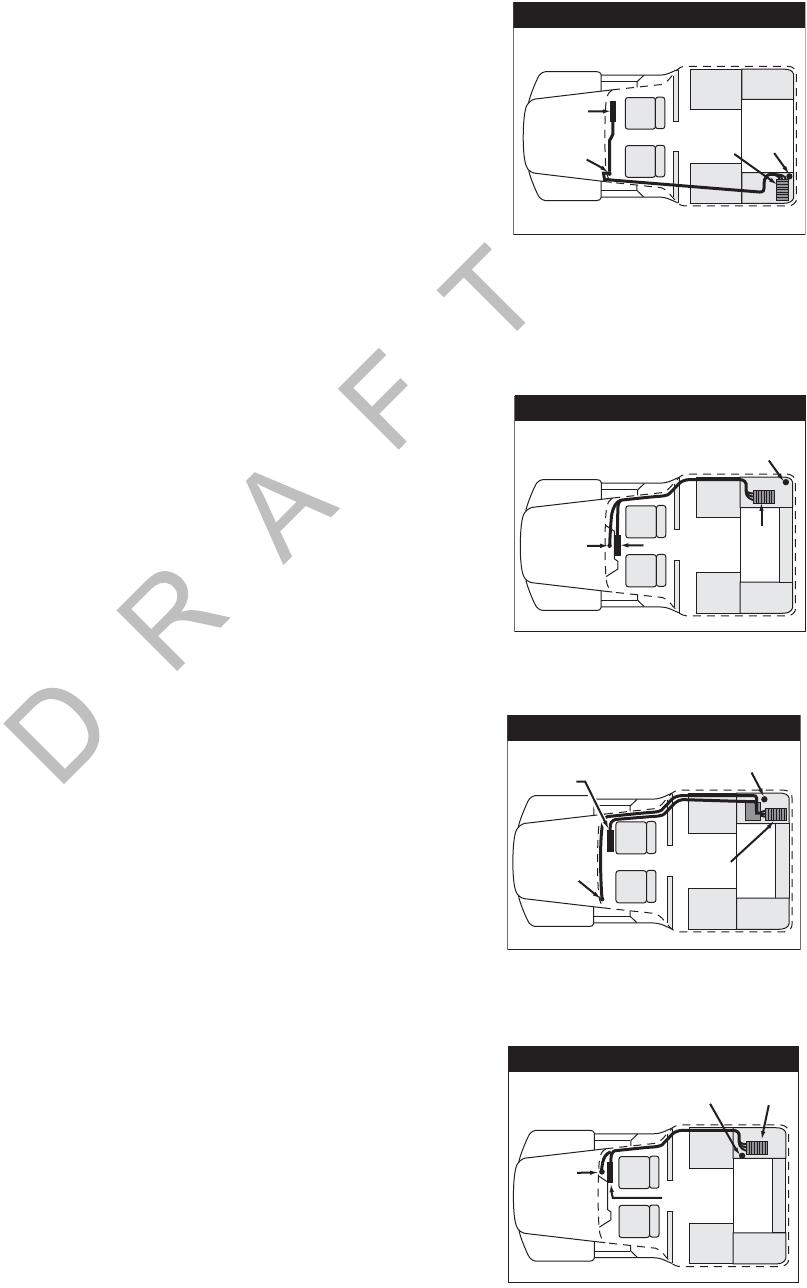
80-J9968-1 Rev. A MAY CONTAIN U.S. AND INTERNATIONAL EXPORT CONTROLLED INFORMATION 4-5
Installation Planning Conventional Vehicle Types
DO N OT
COPY
Kenworth T2000
• MAS200—Install on side wall or hang under the bunk.
- Install so there is always SD card slot access.
•DIU200—Install on passenger side glovebox.
• Cables—Route externally.
- Connect power cable to key switch.
- Cables exit/enter sleeper floor near MAS200.
- Cables enter/exit cab through firewall high on passenger side. Look for rubber plugs.
- Drill a 1" hole in floor of side box for antenna cable. A hole already exists in the firewall
to route cables to the passenger side fuse panel.
Volvo
• MAS200—Install on side wall or hang under the bunk.
- Install so there is always SD card slot access.
•DIU200—Install on engine cover/dog house.
• Cables—Route internally.
- Connect power cable to electrical panel in
top center of dash.
- Drill a 1" hole in floor of side box for antenna cable.
Peterbilt 378/379
• MAS200—Install on side wall or hang under the bunk.
- Install so there is always SD card slot access.
•DIU200—Install behind passenger seat.
• Cables—Route display cables internally or externally.
- Connect power cable to solenoid behind
pyrometer panel.
- Cables exit/enter the sleeper floor near MAS200.
- Cables enter/exit cab through firewall, high on passenger side. Use existing cable path.
Remove map box.
- Drill a 1" hole in floor of side box for antenna cable.
Peterbilt 387
• MAS200—Install on side wall or hang under the bunk.
Kenworth
Display-
face of
map box
Power-
key switch MAS
Antenna
cable
access
hole
Display
Electrical
Panel
Antenna cable
access hole
MAS
Volvo
Peterbilt
Display
Power-
solenoid
behind
pyrometer
panel
MAS
Antenna cable
access hole
Existing
heater
box
Display
Power-
Main
Power Bus
Antenna cable
access hole MAS
Peterbilt

Straight Truck Vehicle Types (All Makes) Installation Planning
4-6 MAY CONTAIN U.S. AND INTERNATIONAL EXPORT CONTROLLED INFORMATION 80-J9968-1 Rev. A
DO NOT COPY
- Install so there is always SD card slot access.
•DIU200—Install on face of connector panel.
• Cables—Route externally.
- Drill a 1" hole in floor of side box for antenna cable.
Mack
• MAS200—Install on side wall or hang under the bunk.
- Install so there is always SD card slot access.
•DIU200—Install on face of connector panel.
• Cables—Route externally.
- Drill a 1" hole in floor of side box for antenna cable.
Straight Truck Vehicle Types (All Makes)
• MAS200—Install on side wall or hang under bunk.
- Install so there is always SD card slot access.
•DIU200—Install where space allows/customer preference.
• Cables—Route externally or internally.
- Tilt cabs may require longer cables.
- Drill a 1" hole in floor of side box for antenna cable.
Cabover Engine Vehicle Types (All Makes)
• MAS200—Install on side wall or hang under bunk.
- Install so there is always SD card slot access.
•DIU200— Install on dash.
• Cables—Route internally.
- Connect power cable to main bus or keyswitch.
- Drill a 1" hole in floor of side box for antenna cable.
Display
Power-
Main
Power Bus
Antenna cable
access hole MAS
Mack
Straight Trucks
Fixed Cab
Fixed Cab + Sleeper Outdoor
Unit
Outdoor
Unit
Display
Unit
Display
Unit
MAS
Power Bus/
Key Switch
Power Bus/
Key Switch
MAS
MAS
Antenna cable
access hole
Display
Electrical
Panel
Cabover Engine

80-J9968-1 Rev. A MAY CONTAIN U.S. AND INTERNATIONAL EXPORT CONTROLLED INFORMATION 4-7
Installation Planning Special Cable Ordering Instructions for Tilt Cabs
DO N OT
COPY
Special Cable Ordering Instructions for Tilt Cabs
• Typically, the antenna cable must be routed through the cab
pivot point to allow for the tilt.
• In most tilt cab vehicles, this routing requires a longer
cable than the standard cable.
• When ordering the MCP200, specify the length of the
cable(s) you need.
Tilt Cab
Pivot Point
Display
Unit
Power Bus/
Key
Switch MAS
Longer
Cable
Outdoor
Unit
Tilt Cab
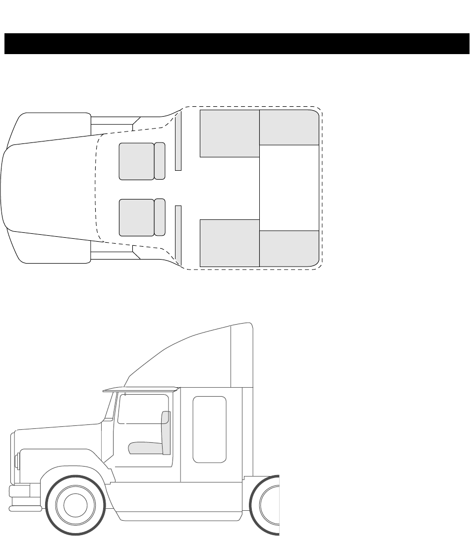
Installation Planning Worksheets for the MCP200 Components Installation Planning
4-8 MAY CONTAIN U.S. AND INTERNATIONAL EXPORT CONTROLLED INFORMATION 80-J9968-1 Rev. A
DO NOT COPY
Installation Planning Worksheets for the MCP200 Components
Conventional Vehicle
User Interface Device:
Communication Unit:
Cables:
Access Holes:
Locations
OM/E0093-152
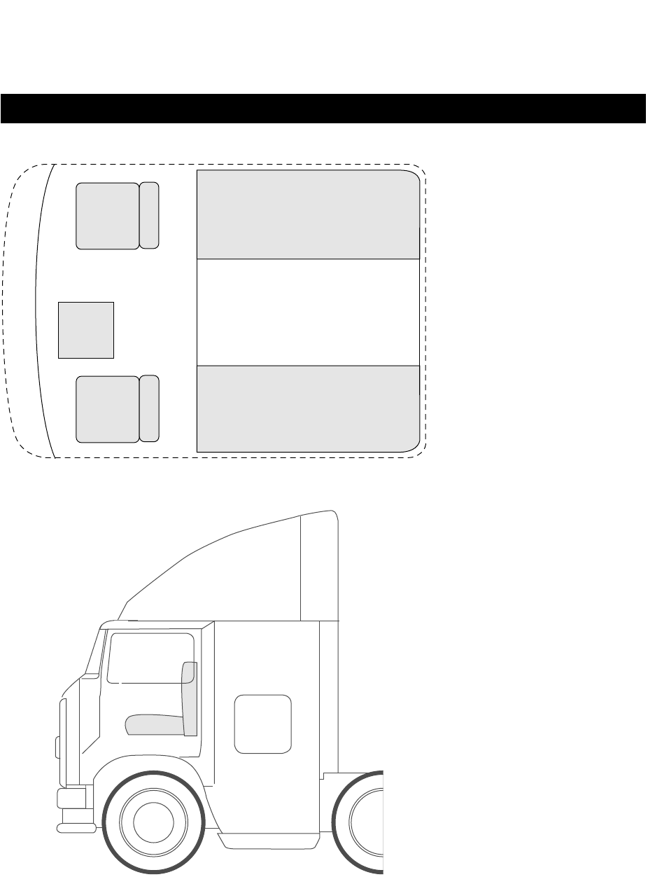
80-J9968-1 Rev. A MAY CONTAIN U.S. AND INTERNATIONAL EXPORT CONTROLLED INFORMATION 4-9
Installation Planning Installation Planning Worksheets for the MCP200 Components
DO N OT
COPY
Cab Over Engine
Installation Planning Worksheet
User Interface Device:
Communication Unit:
Cables:
Access Holes:
Locations
OM/E0093-151
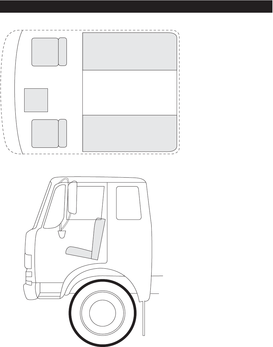
Installation Planning Worksheets for the MCP200 Components Installation Planning
4-10 MAY CONTAIN U.S. AND INTERNATIONAL EXPORT CONTROLLED INFORMATION 80-J9968-1 Rev. A
DO NOT COPY
Day Cab
User Interface Device:
Communication Unit:
Cables:
Access Holes:
Locations
OM/E0093-153

80-J9968-1 Rev. A MAY CONTAIN U.S. AND INTERNATIONAL EXPORT CONTROLLED INFORMATION 4-11
Installation Planning Tools and Supplies Recommended for Installations
DO N OT
COPY
Tools and Supplies Recommended for Installations
Qualcomm Approved Sealants
Essential Tools Miscellaneous Tools
• Standard Combination Wrench Set Measuring Tape
• Diagonal Wire Cutters Rachet/Sockets
• Wire Strippers Adjustable Wrench
• 3/8" Drive Standard Deep Well Socket Set with rachet Level
• Butt Splice Crimping Tool Debur Tool
• Screwdrivers: Phillips #2 and Slotted Flush Cutters
• Torx Drivers: #10, #20, #25 Hacksaw
• Volt/ohm Meter Hammer
• 1/4" Drill Bit and assorted size bits Utility Knife
• 1-1/2" Hole Saw Files (flat, round)
• 3/8" Cordless Drill (this will speed up installation time) Channel Locks
• Radio Removal Tool “U” Straight Awl
1/4" Drive Standard Deep Well Socket Set with
rachet
Miscellaneous Supplies
• Silicone Sealant or Refrigeration/Tar Tape Flash/Drop Light
• Assorted Ring Terminals
• Assorted Butt Splices
• Electrical Tape
Items marked with a bullet (•) are considered necessary, must-have tools and supplies required to perform an
installation. Additional tools may be required to facilitate certain installations and for maintenance.
Sealant, Lubricant, or Liquid Acceptable For Required For
Refrigeration/tar tape
(supplied) Sealing exterior to interior
holes. Sealing 1" hole for
antenna cable.
Silicone sealant Sealing exterior to interior
holes. Sealing bolt holes for
antenna mounting
brackets.

Qualcomm Approved Sealants Installation Planning
4-12 MAY CONTAIN U.S. AND INTERNATIONAL EXPORT CONTROLLED INFORMATION 80-J9968-1 Rev. A
DO NOT COPY
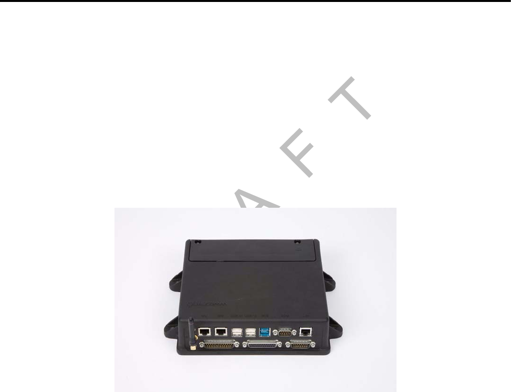
80-J9968-1 Rev. A MAY CONTAIN U.S. AND INTERNATIONAL EXPORT CONTROLLED INFORMATION 5-1
DO NOT COPY
5
Mobile Application Server 200 (MAS200) Installation
Topics in this chapter provide general guidelines and instructions for installing the MAS200
and connecting the cables to the MAS200.
General Installation Guidelines . . . . . . . . . . . . . . . . . . . . . . . . . . . . . . . . . . . . . . . . 5-2
Installing the Backup Battery into the MAS200 . . . . . . . . . . . . . . . . . . . . . . . . . . . . 5-2
Installing the MAS200 into the Mounting Surface . . . . . . . . . . . . . . . . . . . . . . . . . . 5-3
Installing the Power Cable . . . . . . . . . . . . . . . . . . . . . . . . . . . . . . . . . . . . . . . . . . . . 5-5
Grounding Guidelines . . . . . . . . . . . . . . . . . . . . . . . . . . . . . . . . . . . . . . . . . . . . . . . 5-7
Installing the Accessory Cable. . . . . . . . . . . . . . . . . . . . . . . . . . . . . . . . . . . . . . . . . 5-7
For technical questions, contact Qualcomm Enterprise Services (QESSM) Customer Support.
Customer Support is staffed 24 hours a day, 365 days a year:
In the United States, call 800-541-7490
In Canada, call 800-863-9191

General Installation Guidelines Mobile Application Server 200 (MAS200) Installation
5-2 MAY CONTAIN U.S. AND INTERNATIONAL EXPORT CONTROLLED INFORMATION 80-J9968-1 Rev. A
DO NOT COPY
General Installation Guidelines
1. Install the backup battery into the MAS200.
2. Install the MAS200 onto the mounting surface.
3. Connect cables to the MAS200.
Installing the Backup Battery into the MAS200
Install the backup battery before installing the MAS200.
1. Open the battery door on the MAS200 using a Torx #10 driver.
2. Hold the backup battery in a vertical position with the connector facing down.
3. Insert the backup battery connector into the keyed mating connector in the MAS200.
05AAA_45QMCP
Battery door
removed for clartiy
Rotate tab up
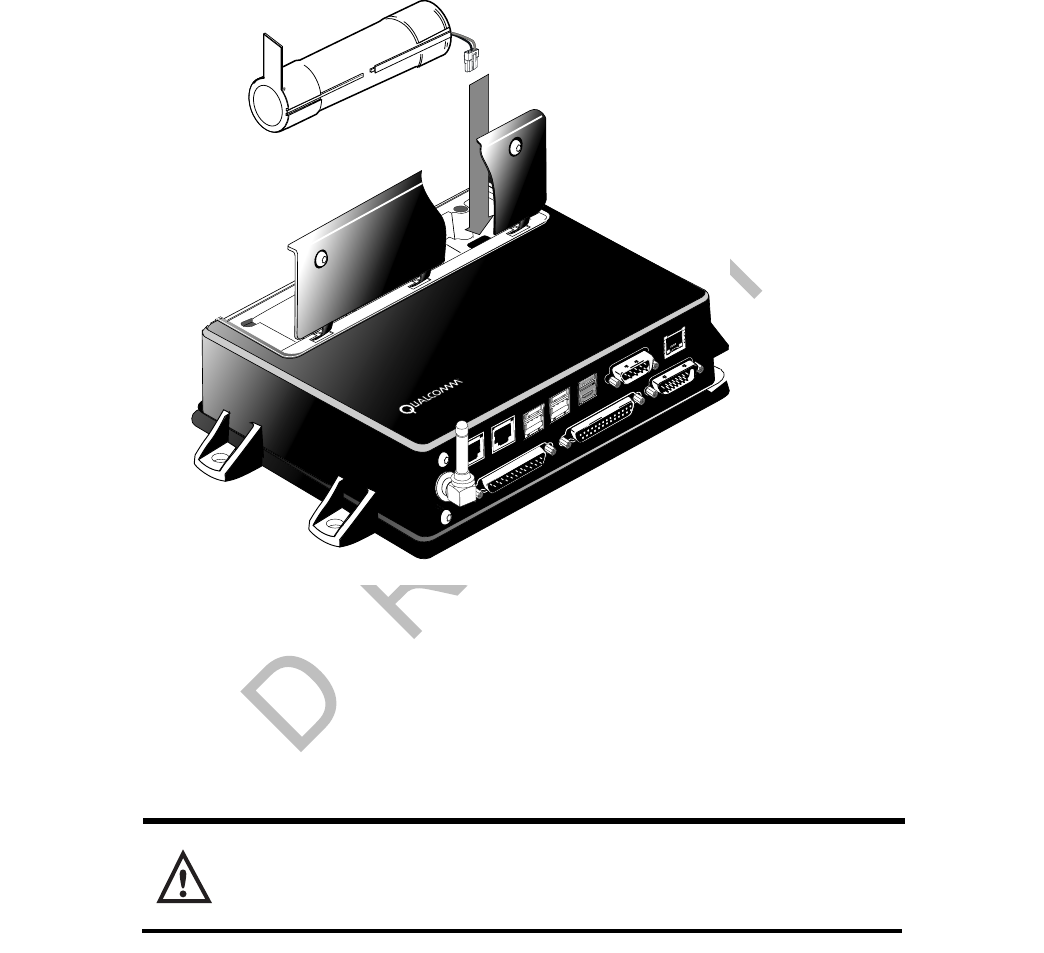
80-J9968-1 Rev. A MAY CONTAIN U.S. AND INTERNATIONAL EXPORT CONTROLLED INFORMATION 5-3
Mobile Application Server 200 (MAS200) Installation Installing the MAS200 into the Mounting Surface
DO N OT
COPY
4. Rotate the backup battery into a horizontal position and place in the MAS200.
5. Close door and tighten the T10 Torx screws using a hand tool. Do not overtighten the
door screws.
Installing the MAS200 into the Mounting Surface
Selecting a Mounting Location
Caution
The MAS200 is not watertight. DO NOT get it wet. Do not locate the MAS200 where
it could come into contact with liquids or solvents.
Adequate Clearance
The minimum requirements for adequate clearance around the MAS200 for ventilation,
cooling, and easy access are:
• Sides and back of unit—1".
• Top of unit—1".
• Top of unit—3" to open the battery door and access the battery.
• Front of unit—6" to allow for proper cable bend diameter exiting the unit.
09AAA_01
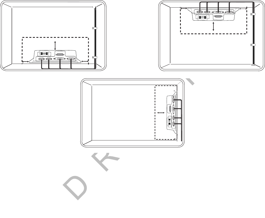
Selecting a Mounting Location Mobile Application Server 200 (MAS200) Installation
5-4 MAY CONTAIN U.S. AND INTERNATIONAL EXPORT CONTROLLED INFORMATION 80-J9968-1 Rev. A
DO NOT COPY
Location and Orientation
• When possible, do not install the MAS200 on the floor of the vehicle.
• Preferably, install the MAS200 on the vertical side wall.
• If possible, install the MAS200 in a storage compartment.
• Choose a location that provides easy access to the SD card slot and visibility to LEDs
located inside the SD card slot.
• Choose a location where the MAS200 will not come into contact with liquids or solvents.
• Choose a location where tire chains or other tools will not likely be stowed on top of the
unit or cables. Do not mount the unit near items that may fall on it or bump cable
connections.
• Choose a location for the MAS200 that is structurally sound. The surface must support the
full weight of the MAS200 under all circumstances.
• Choose a location that provides for the various cable lengths.
• In cabover vehicles, install the MAS200 in the rear of the storage compartment. In this
location, tools or tire chains will not fall on top of the unit when the cab is tilted up.
• Be sure to provide enough room for cable bends or the removal of cables for servicing (4"
to 6" is recommended).
• Install the MAS200 so that the unit, cables, and any accessories can be serviced in the
future.
1"
1"
3"
DSPL SDM I / 0
UI
PWR
05AAA_237A
05AAA_237B
1"
1"
3"
DSPL SDM I / 0
UI
PWR
1"
1"
3"
05AAA_237
DSPL SDM I / 0
UI
PWR

80-J9968-1 Rev. A MAY CONTAIN U.S. AND INTERNATIONAL EXPORT CONTROLLED INFORMATION 5-5
Mobile Application Server 200 (MAS200) Installation Securing the MAS200
DO N OT
COPY
Securing the MAS200
• Tighten the four self-drilling screws into the mounting surface.
Installing the Power Cable
• Connects MAS200 to vehicle’s electrical power source.
Power Cable Run
• Run direction—Route the power cable from the MAS200 to the power connection points.
• Routing location—Route internally or externally. If routed externally, use the supplied
convoluted tubing.
• Cable dressing—Store and secure excess cable.
Power Cable Routing
1. Select one of the following electrical power interface locations on the vehicle:
•Key switch
• Fuse panel
•Bus bar
• Circuit breakers
2. If needed, temporarily remove the two fuses from the fuse holders on the end of the
cable.
3. Route the fuse end of the power cable from the MAS200 location into the cab of the
vehicle.
4. Re-install the fuses onto the appropriate wires.
5. Power on the MAS200 when ready.
Low Voltage Disconnects (LVDs)
• Removes “non-critical” loads, such as TVs, radios, and microwaves from the truck battery
when operating these items without the vehicle running. This ensures that there will be
enough battery power left to start and run the vehicle.
• Do not wire the Qualcomm® MCP200 through any LVD device as this will affect the normal
operation of the system. When the LVD is engaged:
- MCP200 will not transmit or receive messages
- Panic button will not operate
- Tamper detection will not work
- Vehicle position will be lost
- Backup battery life will be significantly reduced
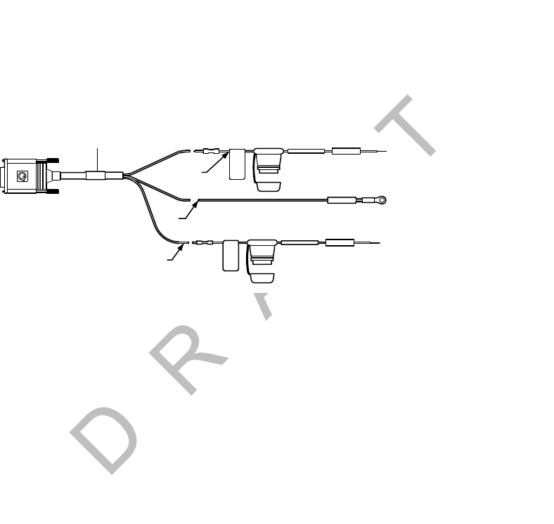
Power Cable Wire Connections Mobile Application Server 200 (MAS200) Installation
5-6 MAY CONTAIN U.S. AND INTERNATIONAL EXPORT CONTROLLED INFORMATION 80-J9968-1 Rev. A
DO NOT COPY
Power Cable Wire Connections
• Vehicle battery supplies power to the MAS200.
• The three required connections that you must make at the fuse end of the power cable:
- Chassis ground
- +12/24 VDC Battery (Main) (unswitched)
- +12/24 VDC Ignition (switched)
• Never wire the constant BAT+ connection or the IGNITION connection to the Accessory
position. See Appendix A for detailed pin and wire callouts.
1. Connect the black BAT RTN wires to a good grounding surface on the vehicle chassis or
one that is connected to the chassis. Refer to Grounding Guidelines on page 5-7 for
more information.
2. Connect the yellow BAT+ wire to an unswitched (Main) +12/24 VDC power source, such
as the hot side of the vehicle main wiring bus, the battery side of the ignition switch, or
the battery side of the fuse block (not the load side). This bus provides constant +12/24
VDC to the MCP200 and must not be connected to the accessory bus or any other
switched bus.
3. Connect the white IGNITION wire to the switched (ignition) +12/24 VDC power source,
such as the ignition side of the ignition (key) switch or the ignition side of the fuse block.
• +12/24 VDC should be present on the IGNITION wire only when the ignition switch is
in the ON position, not in the OFF or Accessory position.
Power Cable
10-AMP
3-AMP
BAT+
BAT RTN
BLACK
IGNITION
WHITE
YELLOW
3-AMP

80-J9968-1 Rev. A MAY CONTAIN U.S. AND INTERNATIONAL EXPORT CONTROLLED INFORMATION 5-7
Mobile Application Server 200 (MAS200) Installation Grounding Guidelines
DO N OT
COPY
Grounding Guidelines
• Create clean, secure, tight, metal-to-metal grounds.
• If grounding terminals are not available, remove the paint from the surface of the firewall
or other metal connected to the chassis to make the ground.
• Remove the paint from the metal and tighten the bolt for a good metal-to-metal ground
connection.
Installing the Accessory Cable
• Connects the MCP200 to the optional remote control device (RCD) for text-to-speech, the
J1708/1587 data link, and other vehicle inputs and optional system devices.
• Provides necessary wiring for optional system features, such as display screen disabling,
the SensorTRACS® system, TrailerTRACS® asset management, buzzer, RMWL, panic
button and other security devices.
• Two accessory cables available:
- primary accessory cable
- secondary accessory cable
- standard length of either cable is 20 feet
- See Appendix A for detailed wiring diagrams.
Metal surface
No
Paint
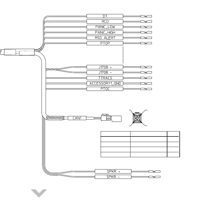
Cable Run Mobile Application Server 200 (MAS200) Installation
5-8 MAY CONTAIN U.S. AND INTERNATIONAL EXPORT CONTROLLED INFORMATION 80-J9968-1 Rev. A
DO NOT COPY
Primary Qualcomm® MCP200 Accessory Cable
• Connects accessories and options, and the optional RCD and speaker to the MAS200 for
text-to-speech (TTS) play.
• Supports wiring for J1708/J1587, J1939, Panic Button, PTOC, TrailerTRACS.
Secondary Qualcomm® MCP200 Accessory Cable
• See Appendix A for detailed pin and wire callouts.
Cable Run
• Run direction—Run the loose conductor end of the cable from the MAS200 to the dash
area. (The connector is too large to pass through most access holes.)
• Routing location—Route internally or externally. Use existing cable runs.
• Cable dressing—Stow and secure any loose wires. Use convoluted tubing for cables run
externally.
• Installation instructions for optional accessories which use the accessory cable are
provided in later chapters of this guide.
• Before connecting the accessory cable to the MCP200, inspect the connectors to make
sure they are not damaged and the pins are not bent. Do not attempt to straighten bent
pins. This further weakens the pins and results in cable failure.
09AAA_014A
WHT/BLU 20WHT/BLU 20
BLU/WHT 20BLU/WHT 20
GRN 22GRN 22
GRN 22
RED 22RED 22
RED 22
BRN 22BRN 22
BRN 22
BLU/BLK 22BLU/BLK 22
BLU/BLK 22
BLU/RED 22BLU/RED 22
BLU/RED 22
BLU 22BLU 22
BLU 22
VIO/ORN 22VIO/ORN 22
VIO/ORN 22
VIO/RED 22VIO/RED 22
VIO/RED 22
BLU/GRN 22BLU/GRN 22
BLU/GRN 22
VIO 22VIO 22
VIO 22
BLU/YEL 22BLU/YEL 22
BLU/YEL 22
BLU/VIO 22BLU/VIO 22
BLU/VIO 22
BLU/GRA 22BLU/GRA 22
BLU/GRA 22
(CAN_D(PWR))(CAN_D(PWR))
(CAN_A(RX))(CAN_A(RX))
PIN 3
PIN 1
PIN 4
PIN 2
WHT/BRN 22WHT/BRN 22
BRN/WHT 22BRN/WHT 22
(CAN_B(TX))(CAN_B(TX))
(CAN_C(GND))(CAN_C(GND))
PIN
SIGNAL
COLOR
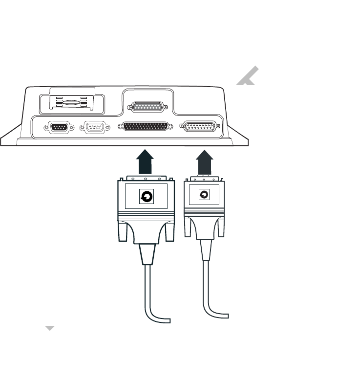
80-J9968-1 Rev. A MAY CONTAIN U.S. AND INTERNATIONAL EXPORT CONTROLLED INFORMATION 5-9
Mobile Application Server 200 (MAS200) Installation Connecting Cables to the MAS200
DO N OT
COPY
Connecting Cables to the MAS200
1. Inspect all connectors for bent pins.
2. Only hand-tighten the thumb screws on the connector.
3. Align the connector so it is straight before sliding into position.
4. Connect the accessory cable into the I/O slot.
5. Connect the power cable into the PWR slot.
05AAA_222DD
DSPL
DSPL
SDM
SDM
I / 0
I / 0
UI
UI
PWR
PWR
Accessory
Cable
Power
Cable

Connecting Cables to the MAS200 Mobile Application Server 200 (MAS200) Installation
5-10 MAY CONTAIN U.S. AND INTERNATIONAL EXPORT CONTROLLED INFORMATION 80-J9968-1 Rev. A
DO NOT COPY
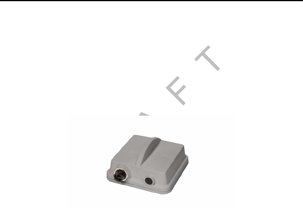
80-J9968-1 Rev. A MAY CONTAIN U.S. AND INTERNATIONAL EXPORT CONTROLLED INFORMATION 7-1
DO NOT COPY
7
Wireless Interface Box 200 (WIB200) Antenna Installation
Topics in this chapter provide general guidelines and instructions for installing the wireless
interface box 200 (WIB200) antenna.
General Installation Guidelines . . . . . . . . . . . . . . . . . . . . . . . . . . . . . . . . . . . . . . . . 7-2
Option A—Antenna Installation Using VHB Tape. . . . . . . . . . . . . . . . . . . . . . . . . . . 7-2
Option B—Mount Method Installation Using Hardware . . . . . . . . . . . . . . . . . . . . . . 7-3
Routing the WIB200 Cable. . . . . . . . . . . . . . . . . . . . . . . . . . . . . . . . . . . . . . . . . . . . 7-4
Connecting the Antenna Cable to the MAS200 . . . . . . . . . . . . . . . . . . . . . . . . . . . . 7-4
For technical questions, contact Qualcomm Enterprise Services (QESSM) Customer Support.
Customer Support is staffed 24 hours a day, 365 days a year:
In the United States, call 800-541-7490
In Canada, call 800-863-9191
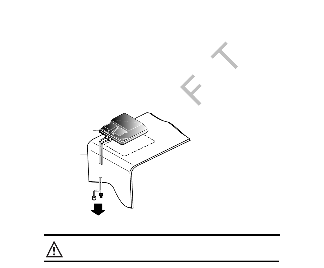
General Installation Guidelines Wireless Interface Box 200 (WIB200) Antenna Installation
7-2 MAY CONTAIN U.S. AND INTERNATIONAL EXPORT CONTROLLED INFORMATION 80-J9968-1 Rev. A
DO NOT COPY
General Installation Guidelines
1. Orient the antenna on the exterior of the vehicle roof.
2. Connect and route the cable.
3. Connect the antenna cable to the WIB200.
The antenna can be installed using tape or screws.
• If you are using a VHB tape, see Option A—Antenna Installation Using VHB Tape on
page 7-2.
• If you are using self-drilling screws, see Option B—Mount Method Installation Using
Hardware on page 7-3.
Option A—Antenna Installation Using VHB Tape
• Attaches to the backside of the vehicle roof without drilling.
Caution
Do not use VHB tape on chrome surfaces.
Antenna Surface Preparation
1. Pick a location toward the back of the vehicle roof.
2. Ensure that the vehicle mounting surface is flat.
3. Verify that the cable routing will adequately reach the bottom of the TDM where the
connection is required.
4. Use alcohol pad to ensure that the vehicle mounting surface is free of dirt and wax.
Terrestrial
Antenna
To TDM
Back of
Truck Cab
01AAJ_79cQMCP
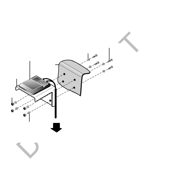
80-J9968-1 Rev. A MAY CONTAIN U.S. AND INTERNATIONAL EXPORT CONTROLLED INFORMATION 7-3
Wireless Interface Box 200 (WIB200) Antenna Installation Option B—Mount Method Installation Using Hardware
DO N OT
COPY
5. Apply the tape primer evenly across the vehicle mounting surface. Wait five minutes
before installing the antenna bracket.
6. Remove the backing from the VHB tape. Position the vertical bracket assembly up to
the mounting surface. Apply even pressure until fully adhered to the mounting surface.
7. Connect and route the cables according to the cable routing instructions on page 7-4.
Option B—Mount Method Installation Using Hardware
• Attaches to the backside of the vehicle roof by using self-drilling screws.
Mount Surface Preparation
1. Use alcohol pad to ensure that the vehicle mounting surface is free of dirt and wax.
2. Using a razor knife, cut the adhesive tape from the four vertical bracket mounting holes.
3. Using the vertical bracket as a template, hold it against the mounting surface and mark
the mounting holes.
4. Mount the bracket over the holes.
5. Tighten the four self-drilling screws into the mounting surface with a Torx #25 driver.
Terrestrial
Antenna
To TDM
01AAJ_79dQMCP
4X#10 Washer
4X#10 Bolt
4X#10 Washer
4X#10 Nut
Back Of
Truck Cab
Vertical
Mounting
Bracket
Antenna
Cable
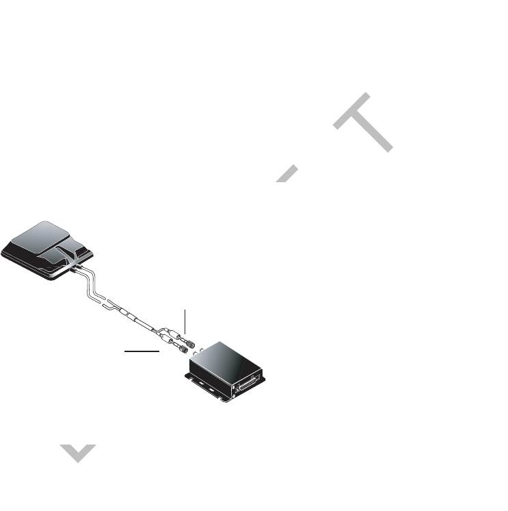
Routing the WIB200 Cable Wireless Interface Box 200 (WIB200) Antenna Installation
7-4 MAY CONTAIN U.S. AND INTERNATIONAL EXPORT CONTROLLED INFORMATION 80-J9968-1 Rev. A
DO NOT COPY
Routing the WIB200 Cable
The antenna cable connects the WIB200 to the MAS200.
• Run direction—Start at the WIB200 and run the cable down to the MAS200.
• Run location—Route the cable internally or externally.
• Cable connectors—Make sure the rubber boots are completely forward so the connectors
are totally covered.
Connecting the Antenna Cable to the MAS200
1. Inspect the antenna cable connectors for damaged or bent pins.
2. Connect the antenna cable connectors to the mobile application server (MAS200).
07AAA_56BQMCP
Terrestrial
Antenna
Terrestrial
Data Modem (TDM)
GPS
Celluar

80-J9968-1 Rev. A MAY CONTAIN U.S. AND INTERNATIONAL EXPORT CONTROLLED INFORMATION 8-1
DO NOT COPY
8
Optional Satellite Data Modem (SDM) Installation
Topics in this chapter provide guidelines for installing the Qualcomm® MCP200 optional
SDM.
General Installation Guidelines . . . . . . . . . . . . . . . . . . . . . . . . . . . . . . . . . . . . . . . . 8-2
Orienting the SDM on the Mount . . . . . . . . . . . . . . . . . . . . . . . . . . . . . . . . . . . . . . . 8-2
Installing Mounting Bolts . . . . . . . . . . . . . . . . . . . . . . . . . . . . . . . . . . . . . . . . . . . . . 8-3
Line-of-Sight Requirements . . . . . . . . . . . . . . . . . . . . . . . . . . . . . . . . . . . . . . . . . . . 8-4
Trailer Swing Area . . . . . . . . . . . . . . . . . . . . . . . . . . . . . . . . . . . . . . . . . . . . . . . . . . 8-5
Installing the SDM Cable . . . . . . . . . . . . . . . . . . . . . . . . . . . . . . . . . . . . . . . . . . . . . 8-5
Connecting the SDM Cable to the MAS200. . . . . . . . . . . . . . . . . . . . . . . . . . . . . . . 8-7
For technical questions, contact Qualcomm Enterprise Services (QESSM) Customer Support.
Customer Support is staffed 24 hours a day, 365 days a year:
In the United States, call 800-541-7490
In Canada, call 800-863-9191

General Installation Guidelines Optional Satellite Data Modem (SDM) Installation
8-2 MAY CONTAIN U.S. AND INTERNATIONAL EXPORT CONTROLLED INFORMATION 80-J9968-1 Rev. A
DO NOT COPY
General Installation Guidelines
1. Orient the SDM on the mount.
2. Connect the SDM.
3. Route the SDM cable.
4. Connect the SDM cable to the MAS200.
Selecting a Mount
See the Outdoor Unit Mount Installation Guide for a complete list of Qualcomm mounts for
specific vehicle types and complete instructions for installing the SDM on the mount.
• Use only Qualcomm-designated mounts for equipment installed in the United States.
• Provide adequate clearance from any nearby structures, such as airdams and exhaust
stacks.
• Position the mount on the driver’s side, if possible, where tree branches and other hazards
will less likely contact the SDM.
• DO NOT install SDMs on headache racks or exhaust pipes.
Caution
Headache racks are mounted to the vehicle frame and there is no shock cushioning.
An SDM mounted on a headache rack risks damage. Qualcomm reserves the right
to charge for replacement or repair of damaged or malfunctioning SDMs which
Qualcomm determines to have failed as a result of installation on the headache
rack.
• DO NOT paint the SDM. Painting the SDM will degrade the performance of the mobile
computing platform (MCP) and void the unit warranty. The SDM mount may be painted.
• DO NOT open the SDM. Removing the radome will void the warranty unless you have
obtained authorization and instructions from Qualcomm. Removing the radome exposes
the MCP antenna to moisture.
• DO NOT overtighten bolts or connectors.
Orienting the SDM on the Mount
• Install the SDM so that it is level when the vehicle is level.
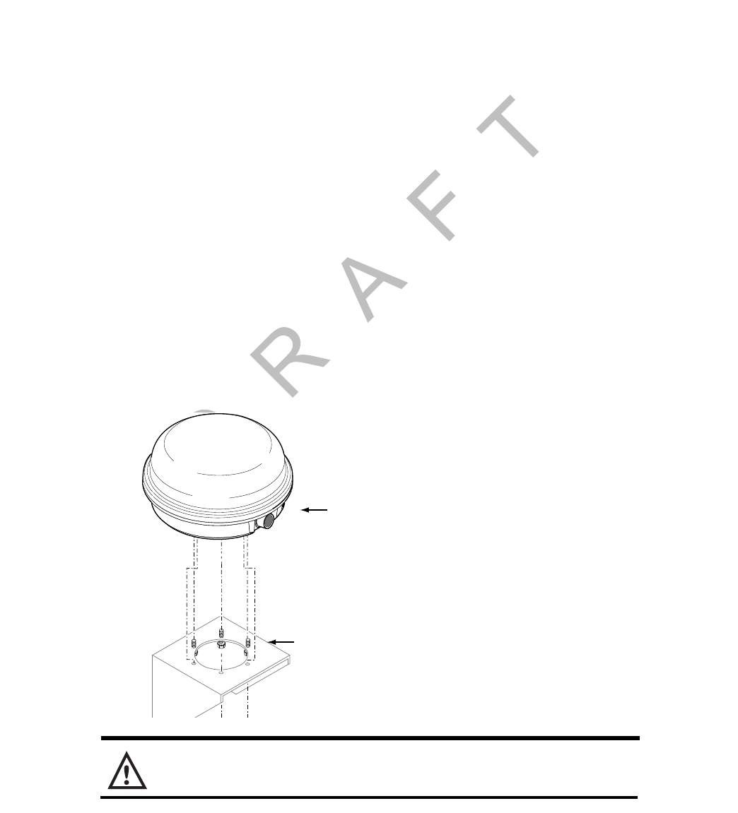
80-J9968-1 Rev. A MAY CONTAIN U.S. AND INTERNATIONAL EXPORT CONTROLLED INFORMATION 8-3
Optional Satellite Data Modem (SDM) Installation Installing Mounting Bolts
DO N OT
COPY
Vehicles with Airdams
• Under a full airdam, orient the SDM so the SDM cable exits toward the front of the
vehicle.
• This orientation reduces the likelihood of water entering the SDM through the connector
port, especially when the vehicle is cleaned with high-pressure water.
Vehicles Without Airdams
• On a vehicle without an airdam and/or the mount is on the rear of the cab, orient the SDM
so the SDM cable connection faces toward the side of the vehicle. See page 3-11 for
cable routing examples.
• This orientation prevents wind-driven rain from pounding the connector, while preventing
trailer swing from hitting the connector.
• Install the SDM so that it does not exceed the Federal D.O.T. mandated maximum legal
height of 13’ 6".
Installing Mounting Bolts
1. Mount the SDM to the mounting bracket using the bolts and washers supplied with the
SDM mounting hardware (or exact substitutions). Normally, bolts longer than 3/4"
should not be used. If longer bolts are needed, such as when the SDM is being
attached to a fiberglass shelf with a plywood base, use 1/4-20 UNC grade 8 or better.
2. Tighten the SDM mounting bolts to the recommended torque of 72 inch/pounds.
Caution
To avoid over-torquing, never use power tools to tighten mounting hardware.
Mounting
Bracket
SDM

Line-of-Sight Requirements Optional Satellite Data Modem (SDM) Installation
8-4 MAY CONTAIN U.S. AND INTERNATIONAL EXPORT CONTROLLED INFORMATION 80-J9968-1 Rev. A
DO NOT COPY
Line-of-Sight Requirements
• SDM requires an unobstructed line-of-sight view to the satellite in order to clearly send and
receive signals.
• SDM must be able to send and receive the signals at a 12° angle above the horizontal
plane of the unit. There must be an unobstructed view of the satellite at all angles above
12°.
The following illustration shows the 12° angle and the maximum allowable height of
objects located at various distances from the SDM centerline.
• An obstruction height of 2.5 feet for every 12 feet away from the SDM centerline is
acceptable. Use this same formula to verify that a trailer hooked up to the vehicle does not
extend above the 12° angle.
• Satellite signal can normally pass through thin layers of glass, fiberglass, and plastic. Thick
layers or obstructions above the 12° angle may block the satellite signal and cause “blind
spots.” Keep blind spots to a minimum:
- Multiple layers of fiberglass, glass, or plastic
- Areas with numerous bends in the fiber glass
- Metal and wood bracing
- Metallic paints and lead-based paints
- Company logos that contain metallic materials
- Metal airdams, metal wings, metal side skirts, air conditioning units, and exhaust
stacks.
• When mounting an SDM, make sure that the mounting surface is strong enough to support
the weight of the SDM and mount.
• The installation must also withstand very strong shock forces exerted by the vehicle when
it is moving.
Maximum Height: 2' 6"
Maximum Height: 2' 1"
Maximum Height: 1' 8"
8' 10' 12'
12˚
Distance From
Centerline
Horizontal
Plane
Satellite
signals
OM/E-0093-42
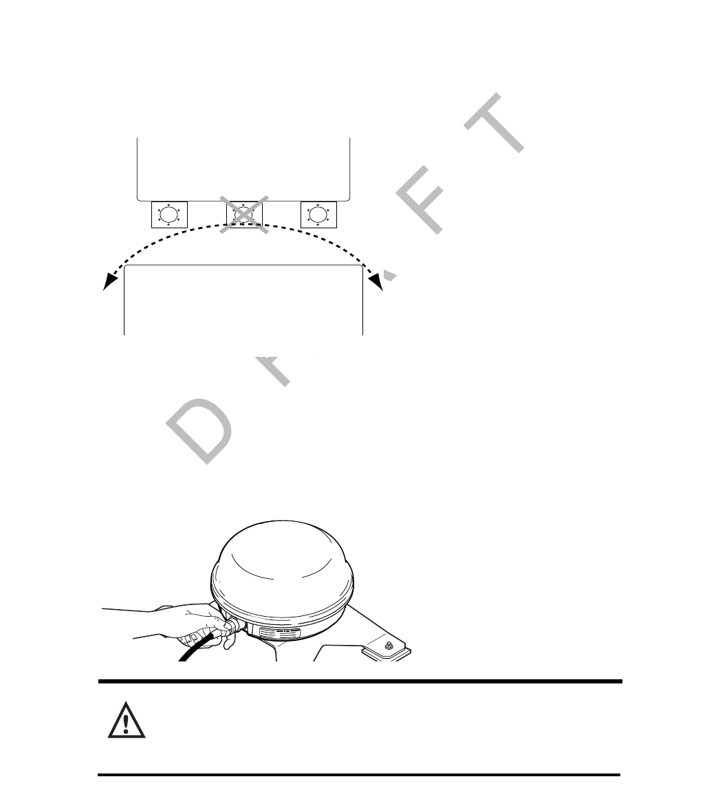
80-J9968-1 Rev. A MAY CONTAIN U.S. AND INTERNATIONAL EXPORT CONTROLLED INFORMATION 8-5
Optional Satellite Data Modem (SDM) Installation Trailer Swing Area
DO N OT
COPY
Trailer Swing Area
• DO NOT position the mount in the rear center of the vehicle. The corner of the trailer could
hit the SDM when the vehicle turns sharply.
• When positioning the SDM on the mount, protect the SDM connector by turning the
antenna so it faces the side and NOT the back of the trailer.
• Make sure that when the “fifth wheel” of a vehicle is fully forward, the trailer clears the
SDM when executing sharp turns or going up ramps.
• If the vehicle will be hauling refrigerated trailers, make sure that the refrigeration unit still
clears the SDM when the driver turns sharply or drives up ramps.
Installing the SDM Cable
• Connects SDM to MAS200.
Connecting the SDM Cable
1. Install the SDM cable on the SDM connector and hand-tighten.
Caution
If the cable does not easily connect to the SDM cable connector, check the part
number of the cable to make sure you are using the SDM cable. The SDM cable is
keyed to avoid an incorrect cable with a similar connector type from being attached.
Cab/Sleeper
Trailer
Trailer Swing Area
Yes
(Recommended)
No Yes
OM/E-0093-87
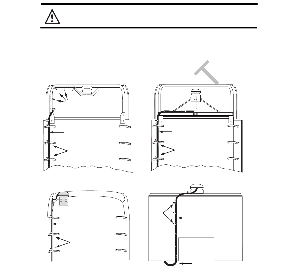
SDM Cable Run Optional Satellite Data Modem (SDM) Installation
8-6 MAY CONTAIN U.S. AND INTERNATIONAL EXPORT CONTROLLED INFORMATION 80-J9968-1 Rev. A
DO NOT COPY
• The SDM connector is weather-resistant; do not weather-proof the SDM connector.
Caution
Do not use refrigeration/tar tape on the SDM connector.
SDM Cable Run
• Run direction—Start at the SDM mount and run the cable down to the MAS200.
• Routing location—Route the cable externally.
• Cable dressing—SDM cable comes with pre-installed convoluted tubing and UV resistant
tie wraps.
SDM Cable Installation
1. Start at the SDM and run the cables down the back of the sleeper/cab and under the
body toward the MAS200.
• Route the cable using existing brackets as tie points.
Convoluted tubing
Service (drip) loop
Tie
wraps
Tie
wraps
Convoluted tubing
Cable tied to existing
boomerang brackets
Convoluted tubing
Cable tied to existing
boomerang brackets
Existing
fiberglass
shelf
Cable tied to existing
boomerang brackets
Convoluted tubing
Drip loop
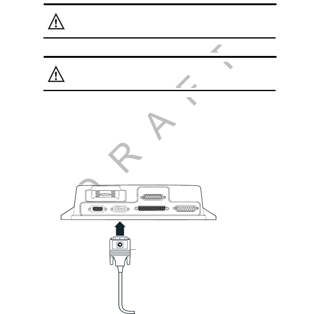
80-J9968-1 Rev. A MAY CONTAIN U.S. AND INTERNATIONAL EXPORT CONTROLLED INFORMATION 8-7
Optional Satellite Data Modem (SDM) Installation Connecting the SDM Cable to the MAS200
DO N OT
COPY
2. Drill an access hole through the bottom of the cab so it enters where the MAS200 is
installed. See Access Holes on page 3-13.
3. Store and coil excess cable near the MAS200.
Caution
Do not tie the cable to the headache rack. Headache racks are mounted to the
chassis and move at different rates than the body.
Caution
Loose cables can cause damage to paint and wear to the fiberglass. Ensure that
the cables are secured to the vehicle with tie wraps at approximately 18" intervals.
Connecting the SDM Cable to the MAS200
1. Inspect the connector for bent pins.
2. Only hand-tighten the thumb screws on the connector.
3. Align the connector so it is straight before sliding into position.
4. Connect the SDM cable into the satellite data modem (SDM) slot.
05AAA_222
E
DSPL
DSPL
SDM
SDM
I / 0
I / 0
UI
UI
PWR
PWR
SDM Cable

Connecting the SDM Cable to the MAS200 Optional Satellite Data Modem (SDM) Installation
8-8 MAY CONTAIN U.S. AND INTERNATIONAL EXPORT CONTROLLED INFORMATION 80-J9968-1 Rev. A
DO NOT COPY
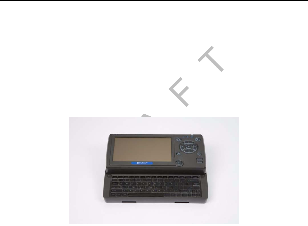
80-J9968-1 Rev. A MAY CONTAIN U.S. AND INTERNATIONAL EXPORT CONTROLLED INFORMATION 9-1
DO NOT COPY
9
Display Interface Unit 200 (DIU200) Installation
Topics in this chapter provide guidelines and instructions for installing the DIU200:
General Installation Guidelines . . . . . . . . . . . . . . . . . . . . . . . . . . . . . . . . . . . . . . . . 9-2
Installing the DIU200 Holster Using Well-nut Fasteners . . . . . . . . . . . . . . . . . . . . . 9-3
Installing the DIU200 Cable . . . . . . . . . . . . . . . . . . . . . . . . . . . . . . . . . . . . . . . . . . . 9-4
Connecting the Display Cable to the DIU200. . . . . . . . . . . . . . . . . . . . . . . . . . . . . . 9-4
Inserting the DIU200 into the Holster. . . . . . . . . . . . . . . . . . . . . . . . . . . . . . . . . . . . 9-5
Connecting the Display Cable to the MAS200. . . . . . . . . . . . . . . . . . . . . . . . . . . . . 9-6
For technical questions, contact Qualcomm Enterprise Services (QESSM) Customer Support.
Customer Support is staffed 24 hours a day, 365 days a year:
In the United States, call 800-541-7490
In Canada, call 800-863-9191
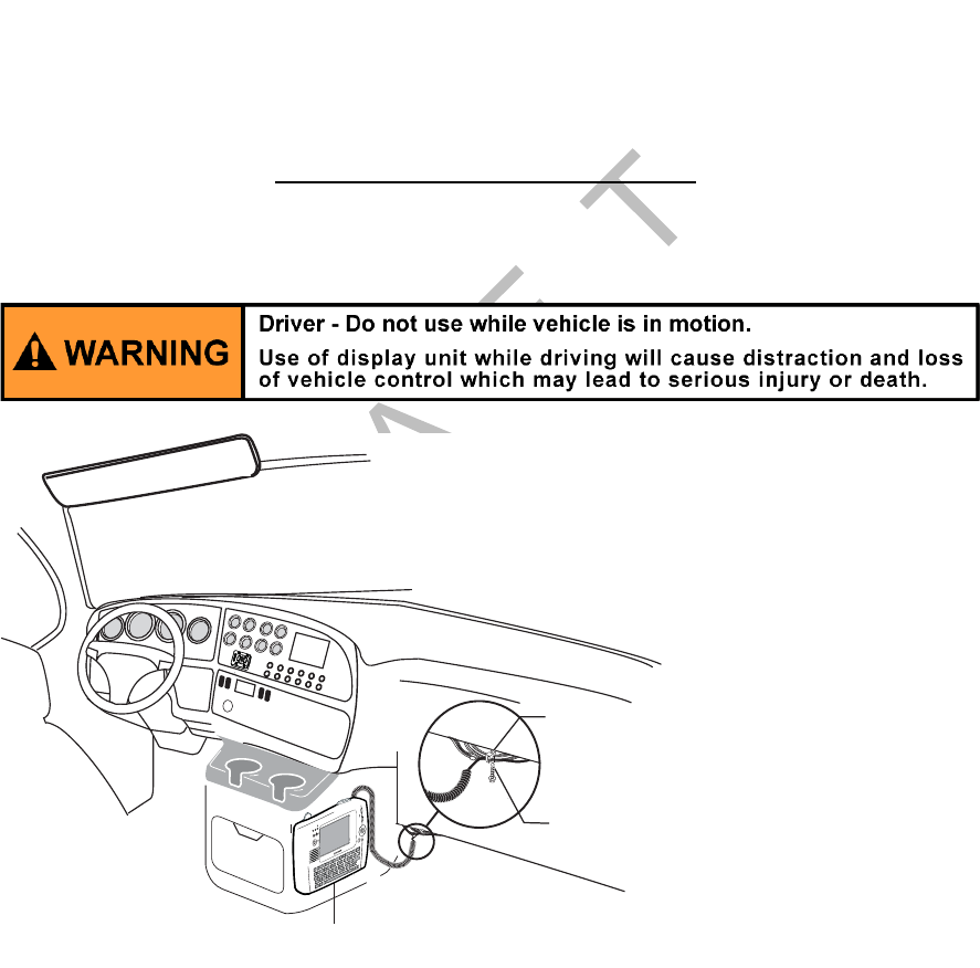
General Installation Guidelines Display Interface Unit 200 (DIU200) Installation
9-2 MAY CONTAIN U.S. AND INTERNATIONAL EXPORT CONTROLLED INFORMATION 80-J9968-1 Rev. A
DO NOT COPY
General Installation Guidelines
1. Install the DIU200 holster.
2. Route and connect the cable.
3. Connect the DIU200 cable to the MAS200.
Selecting a Mounting Location
IMPORTANT SAFETY INFORMATION
Do not locate the display unit where it obstructs the driver’s field of vision, distracts the driver
from the driving task, or interferes with the driver’s operation of controls or displays.
1. Each display unit is equipped with a holster to hold and protect the device when not in
use.
• The holster can be installed inside the cab in locations, such as map box door/glove
compartment door, engine cover/“dog house,” and behind the passenger’s seat/
cabinet wall, depending on the owner’s preference and whether there is a team or
single driver.
• Make sure there is enough clearance to lift the unit out of the holster easily.
• Before you install the device on a map box/glove compartment door, make sure the
driver can still open the map box/glove compartment.
Media Display Unit (MDU)
Tie wrap
the cable for
strain relief
Esc
1
!
2
@
3
#
4
$
5
%
6
^
7
&
8
*
9
(
0
)
=
Backspace
+
Tab
Q
Caps
0
WE R TYUIP
{
[
{
[
Enter
Shift
Ctrl Alt Sym
Delete
Shift
L
K
J
HGFDS
A"
'
M
N
B
V
C
X
Z
V
V
?
!
Opt
Back
Hole Mount Tie
Wrap and Self
Drilling Screw
02AAA_210D

80-J9968-1 Rev. A MAY CONTAIN U.S. AND INTERNATIONAL EXPORT CONTROLLED INFORMATION 9-3
Display Interface Unit 200 (DIU200) Installation Installing the DIU200 Holster Using Well-nut Fasteners
DO N OT
COPY
2. Select an installation location where:
• driver can easily see the message waiting light from his seat
• mounting surface is flat
• device will not be positioned high in the cab
• device will not be stored in constant, direct sunlight
• device will not fall out of the holster when the vehicle is in motion
• device will not limit a passenger’s leg room or block access to the wiring panel or any
other compartments
• device will not interfere with a passenger entering or exiting the vehicle
• device will not adversely impact a passenger in case of a vehicle accident or collision
• driver can easily pull the device toward the driver’s seat
Installing the DIU200 Holster Using Well-nut Fasteners
1. Mount on any rigid surface between .035 and .232 inches thick and able to support the
weight of the DIU200 (3.2 lbs.).
2. Use your display holster as a template to mark the four mounting holes.
3. Drill four .375 (3/8") holes in the positions marked in step 2.
4. Place the well-nut inserts all the way into each .375 hole until the flanges fit firmly
against the mounting surface.
5. Place the holster correctly over the mounting holes.
6. Pass the 10-32 machine screws through the holster and mounting holes and tighten
until snug.
09AAA_07
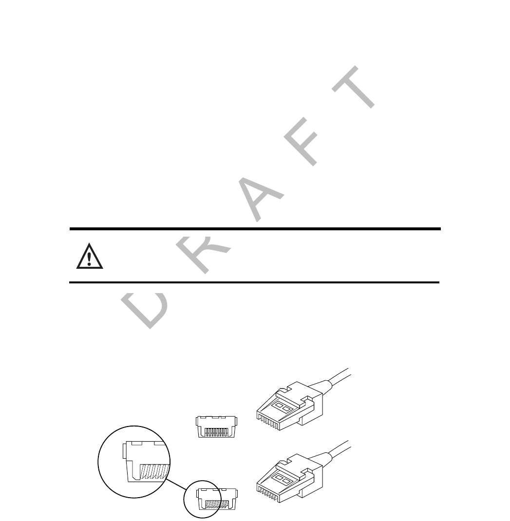
Installing the DIU200 Cable Display Interface Unit 200 (DIU200) Installation
9-4 MAY CONTAIN U.S. AND INTERNATIONAL EXPORT CONTROLLED INFORMATION 80-J9968-1 Rev. A
DO NOT COPY
Installing the DIU200 Cable
• Connects DIU200 to MAS200.
DIU200 Cable Run
• Run direction—In most vehicles, the display unit is mounted in the dash area. Route the
cable from the DIU200 to the MAS200 with the coiled end of the cable at the DIU200 and
the uncoiled end routed to the MAS200. If drilling is necessary, the 9-pin DSUB connector
end of the display cable requires a 1-1/2" hole.
• Routing location—Route the cable internally or externally.
- In a few vehicles, the display unit may be installed in the sleeper. In this case, route the
cable internally to this area.
• Cable dressing—For strain relief, the base of the coil should be secured with tie wraps.
The strain-relief tie wrap is normally positioned at the point where the cable transitions
from a straight cable to a coiled cable.
Connecting the Display Cable to the DIU200
1. If the cable is not yet routed, refer to page 3-11 for routing procedures.
Caution
Do not step on or drop any objects on the display cable connectors. Do not let the
connectors lie on the ground unprotected.
2. Use a #10 Torx driver to remove the DIU200’s back housing.
3. Remove the protective cap on the connector.
• Inspect the connectors for damage and bent pins.
4. Plug in connector.
• Make sure the rubber grommet fits in the grooves of the DIU200.
• Make sure the flat side of the grommet is facing up.
Straight
Bent
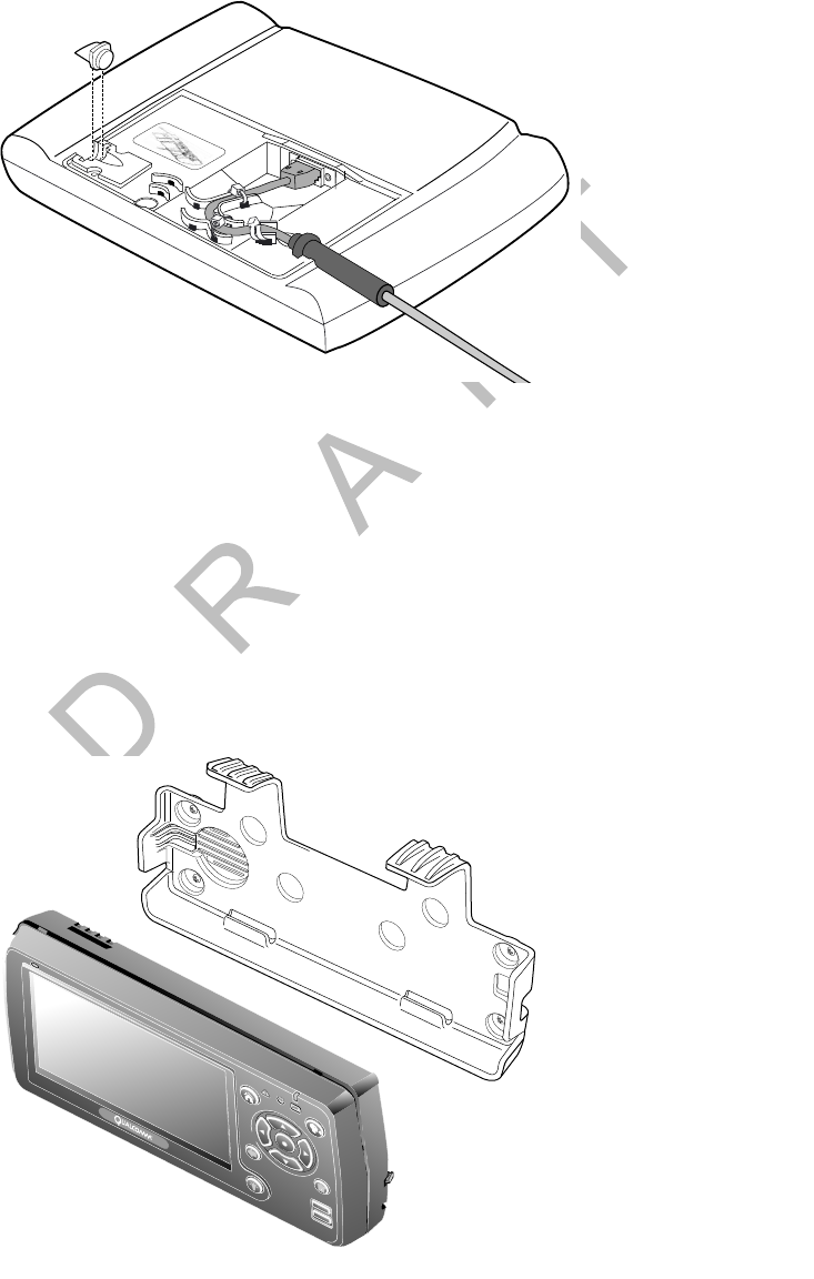
80-J9968-1 Rev. A MAY CONTAIN U.S. AND INTERNATIONAL EXPORT CONTROLLED INFORMATION 9-5
Display Interface Unit 200 (DIU200) Installation Inserting the DIU200 into the Holster
DO N OT
COPY
5. Install and tighten the cable strain tie wraps on the back of the DIU200.
6. Route the display cable through the right or left channel on the back of the DIU200.
7. Reinstall the back housing.
8. Install the rubber plug on the opposite side from where the cable has been run.
9. Secure the cable with tie wrap.
Inserting the DIU200 into the Holster
1. Push bottom of display into lower holster tabs.
2. Push top of display into upper holster tabs.
Cable Routing
Tie Wraps
09AAA_08
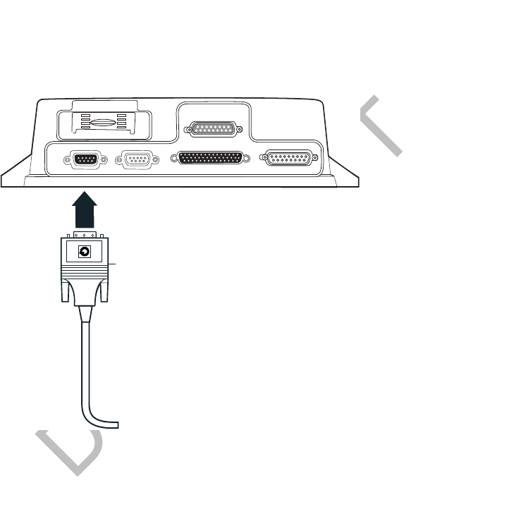
Connecting the Display Cable to the MAS200 Display Interface Unit 200 (DIU200) Installation
9-6 MAY CONTAIN U.S. AND INTERNATIONAL EXPORT CONTROLLED INFORMATION 80-J9968-1 Rev. A
DO NOT COPY
Connecting the Display Cable to the MAS200
1. Inspect the connector for bent pins.
2. Only hand-tighten the thumb screws on the connector.
3. Align the connector so it is straight before sliding into position.
4. Connect the display cable into the DSPL slot.
05AAA_222F
DSPL
DSPL
SDM
SDM
I / 0
I / 0
UI
UI
PWR
PWR
Display Unit Cable

80-J9968-1 Rev. A MAY CONTAIN U.S. AND INTERNATIONAL EXPORT CONTROLLED INFORMATION 10-1
DO NOT COPY
10
Optional Text-to-Speech (TTS) Installation
Topics in this chapter provide guidelines for installing the remote control device (RCD) and
speaker switch cable for the Qualcomm® MCP200 optional text-to-speech (TTS) feature.
This is an option that can be used if the DIU200 is not located where the driver can readily
hear incoming messages.
General Installation Guidelines . . . . . . . . . . . . . . . . . . . . . . . . . . . . . . . . . . . . . . . 10-2
Installing the Remote Control Device (RCD) . . . . . . . . . . . . . . . . . . . . . . . . . . . . . 10-2
Selecting a Speaker. . . . . . . . . . . . . . . . . . . . . . . . . . . . . . . . . . . . . . . . . . . . . . . . 10-3
Option A—Connecting to an Existing or Shared Speaker . . . . . . . . . . . . . . . . . . . 10-4
Option B—Connecting to a Dedicated 8-ohm Speaker . . . . . . . . . . . . . . . . . . . . . 10-6
For technical questions, contact Qualcomm Enterprise Services (QESSM) Customer Support.
Customer Support is staffed 24 hours a day, 365 days a year:
In the United States, call 800-541-7490
In Canada, call 800-863-9191

General Installation Guidelines Optional Text-to-Speech (TTS) Installation
10-2 MAY CONTAIN U.S. AND INTERNATIONAL EXPORT CONTROLLED INFORMATION 80-J9968-1 Rev. A
DO NOT COPY
General Installation Guidelines
1. Install the RCD.
2. Route and connect RCD cable.
3. Route and connect RCD cable to speaker.
Selecting a Mounting Location
• Mount the RCD on the dash panel of the vehicle.
• RCD must be easily accessible to the driver while seated in the driver’s seat, but
cannot interfere in any way with the operation of the vehicle.
• Check Important Safety Information on page -xi when choosing a location.
Installing the Remote Control Device (RCD)
1. Determine a suitable location.
• VHB (very high bond) tape permanently bonds the device to the dash panel.
2. Remove the dash panels to expose the backside of the dash. Check that the area is free
of cable, wires, and/or hoses.
3. Drill a 1/4" hole in the dash panel and debur the hole.
• OPTIONAL: If routing the cable over the dash, use tie wraps to secure the cable.
4. Route cable through the hole and behind the dash panel.
5. Use the alcohol wipe provided to clean the mounting surface of any dirt, oil, or grime.
• OPTIONAL: There are two nutserts on the back of the RCD that can be used instead
of/in addition to the VHB tape. If you use the nutserts, you will need 4-40 x 0.375-
0.412 screws. These screws are not supplied by Qualcomm.
6. Remove the paper backing from the VHB tape and firmly press the RCD onto the
mounting surface. Let it stand for a few minutes to allow surfaces to fully bond.
7. Finish routing the RCD cable to where the accessory cable ends.
Connecting the RCD to the Accessory Cable
1. Butt splice the yellow wire on the RCD cable to the blue/green RCD wire on the
accessory cable.
2. Butt splice the black wire on the RCD cable to the violet COM5 GND wire on the
accessory cable.
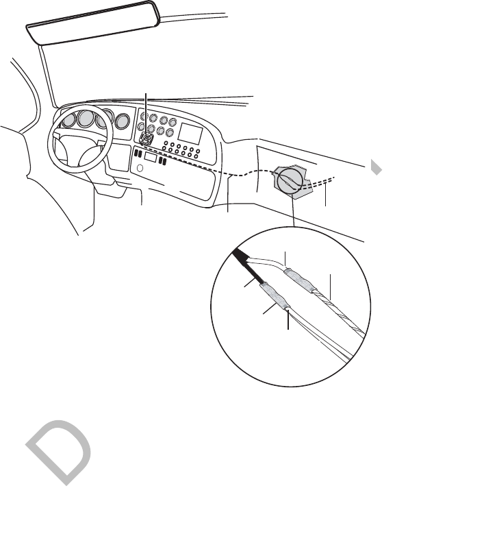
80-J9968-1 Rev. A MAY CONTAIN U.S. AND INTERNATIONAL EXPORT CONTROLLED INFORMATION 10-3
Optional Text-to-Speech (TTS) Installation Selecting a Speaker
DO N OT
COPY
• The COM5 GND wire is also used for the speaker switch cable ground (green wire),
if used. Make both ground connections at the same time.
Selecting a Speaker
Speaker Requirements
There are two basic speaker requirements for TTS:
• Only one speaker should be connected to the MCP200 for text-to-speech play, otherwise
the volume will be very low.
• An 8-ohm speaker, such as a standard CB speaker or standard truck audio speaker, must
be used for text-to-speech play.
Choosing a Speaker
Text-to-speech works with either an existing speaker (typically, the driver’s side door
speaker) that is part of the vehicle’s audio system, or a speaker that can be added for text-to-
speech.
• If you are using a vehicle’s audio system 8-ohm speaker, see Option A—Connecting to an
Existing or Shared Speaker on page 10-4.
• If you are adding a dedicated speaker for TTS, see Option B—Connecting to a Dedicated
8-ohm Speaker on page 10-6.
Remote Control Device (RCD)
05AAA_148B
RCD Cable
RCD
(Blue/Green)
RCD
(Yellow)
Accessory Cable
GND
(Black)
COM5 GND
(Violet)
Speaker
Switch Cable
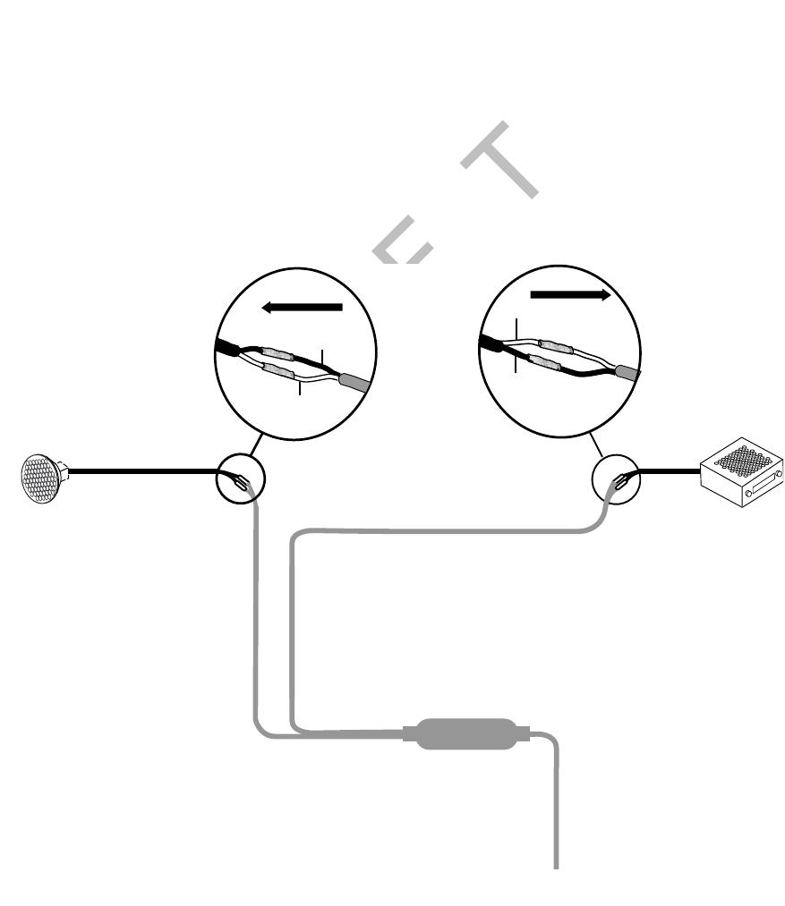
Option A—Connecting to an Existing or Shared Speaker Optional Text-to-Speech (TTS) Installation
10-4 MAY CONTAIN U.S. AND INTERNATIONAL EXPORT CONTROLLED INFORMATION 80-J9968-1 Rev. A
DO NOT COPY
Option A—Connecting to an Existing or Shared Speaker
1. Identify the speaker to be used for message playback. See Speaker Requirements on
page 10-3.
2. Test the audio system prior to installation.
3. Remove audio/radio.
4. Locate the speaker wires to be used for message playback. Refer to Radio Connector
Pin Callouts on page A-11.
5. Find a good location on the speaker wires where they can be cut and where there will
be enough room to work on either side of the cut.
6. Cut the speaker wires.
7. Butt splice the yellow SPKR OUT+ wire on the speaker switch cable to the positive (+)
wire that leads from the speaker.
8. Butt splice the black SPKR OUT- wire on the speaker switch cable to the negative (-)
wire that leads from the speaker.
8-ohm
Door Speaker
SPKR OUT +
(Yellow)
SPKR OUT -
(Black)
To Speaker
VEH AUDIO IN +
(Orange)
VEH AUDIO IN -
(Black)
To Audio
Radio
To Accessory Cable
06AAA_180
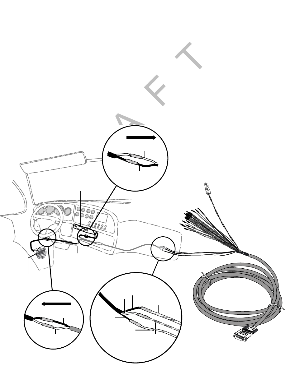
80-J9968-1 Rev. A MAY CONTAIN U.S. AND INTERNATIONAL EXPORT CONTROLLED INFORMATION 10-5
Optional Text-to-Speech (TTS) Installation Connecting Speaker Switch Cable to Accessory Cable
DO N OT
COPY
9. Butt splice the orange VEH AUDIO IN + wire on the speaker switch cable to the positive
(+) speaker wire that leads from the audio.
10. Butt splice the black VEH AUDIO IN - wire on the speaker switch cable to the negative
(-) speaker wire that leads from the audio.
11. Tie wrap loose cabling and reconnect/replace the radio.
Connecting Speaker Switch Cable to Accessory Cable
1. Butt splice the yellow MAS SPKR + wire on the speaker switch cable to the blue/yellow
SPKR + wire on the accessory cable.
2. Butt splice the black MAS SPKR - wire on the speaker switch cable to the blue/violet
SPKR - wire on the accessory cable.
3. Butt splice the green GND wire on the speaker switch cable to the violet COM5 GND on
the accessory cable. As noted on page 10-2, the COM5 GND is a shared ground with
the black RCD wire.
05AAA_148DQMCP
Door
Speaker
Accessory Cable
SPKR -
(Blue/Yellow)
MAS
SPKR -
(Black)
MAS
SPKR +
(Yellow)
COM5 GND
(Violet)
is a shared
ground
Radio /Audio
GND
(Green)
SPKR +
(Blue/Violet)
SPKR OUT +
(Yellow)
SPKR OUT -
(Black)
To Speaker
VEH AUDIO IN +
(Orange)
VEH AUDIO OUT -
(Black)
To Au d i o
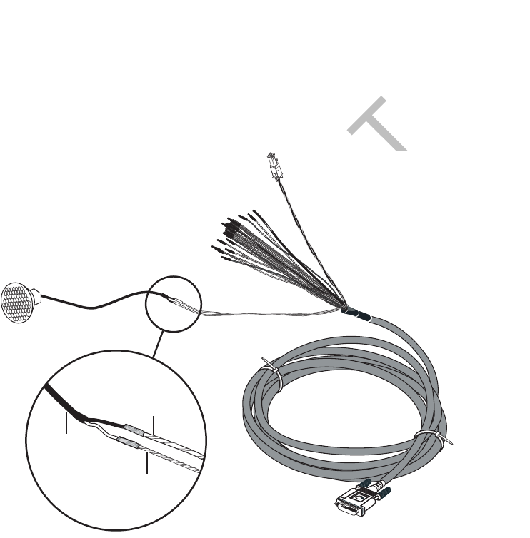
Option B—Connecting to a Dedicated 8-ohm Speaker Optional Text-to-Speech (TTS) Installation
10-6 MAY CONTAIN U.S. AND INTERNATIONAL EXPORT CONTROLLED INFORMATION 80-J9968-1 Rev. A
DO NOT COPY
Option B—Connecting to a Dedicated 8-ohm Speaker
• Connect the dedicated speaker for text-to-speech play directly to the accessory cable:
1. Butt splice the blue/yellow SPKR + wire on the accessory cable to the positive (+) wire
that leads from the speaker.
2. Butt splice the blue/violet SPKR - wire on the accessory cable to the negative (-) wire
that leads from the speaker.
Note
The speaker switch cable is not used if you are adding an external, dedicated speaker.
05AAA_148T
Accessory Cable
SPKR+
(blue/yellow)
SPKR-
(blue/violet)
Speaker
Speaker
Wires

80-J9968-1 Rev. A MAY CONTAIN U.S. AND INTERNATIONAL EXPORT CONTROLLED INFORMATION 11-1
DO NOT COPY
11
Vehicle Data Bus Connections
Topics in this chapter provide the procedures for performing J1939, J1708/J1587, and
traditional sensors (standard speed and RPM) installations.
Vehicle Data Source Overview. . . . . . . . . . . . . . . . . . . . . . . . . . . . . . . . . . . . . . . . 11-2
Vehicle Data Source Selection. . . . . . . . . . . . . . . . . . . . . . . . . . . . . . . . . . . . . . . . 11-3
Guidelines for Connecting to the J1939 Data Bus . . . . . . . . . . . . . . . . . . . . . . . . . 11-3
J1939 Pre-installation Check Out. . . . . . . . . . . . . . . . . . . . . . . . . . . . . . . . . . . . . . 11-4
Option 1—Connecting J1939 Using CAN 1 (for All After-Market Installations) . . . 11-5
Option 2—Connecting J1939 Using CAN0 (for Most OEM Prewires) . . . . . . . . . . 11-8
Connecting J1708 /J1587 . . . . . . . . . . . . . . . . . . . . . . . . . . . . . . . . . . . . . . . . . . 11-10
Verifying Data Source Connectivity . . . . . . . . . . . . . . . . . . . . . . . . . . . . . . . . . . . 11-11
For technical questions, contact Qualcomm Enterprise Services (QESSM) Customer Support.
Customer Support is staffed 24 hours a day, 365 days a year:
In the United States, call 800-541-7490
In Canada, call 800-863-9191

Vehicle Data Source Overview Vehicle Data Bus Connections
11-2 MAY CONTAIN U.S. AND INTERNATIONAL EXPORT CONTROLLED INFORMATION 80-J9968-1 Rev. A
DO NOT COPY
Vehicle Data Source Overview
Qualcomm’s mobile computing platform can use the J1708/J1587 and J1939 data buses, as
well as traditional sensors to monitor critical vehicle data:
• Traditional sensors are used on most pre-1992 trucks.
• J1708/J1587 data bus is used on most 1992–2009 trucks.
• J1708/J1587 and J1939 data buses are available on 2007–2010 trucks.
• J1939 will be the only data bus used on most trucks built after 2010.
These data inputs can be monitored on the vehicle data services (VDS) screens. The vehicle
data source makes this data available to specific applications on the MCP200.
J1939 Data Bus
Qualcomm applications only support 2007 and newer trucks with ECMs that support the SAE
J1939-71, Rev. Nov 2006 standard.
• High speed (250 Kb/sec) data bus.
• Uses a two-wire differential serial bus, which is a network backbone running throughout
the vehicle with several stubs connecting each ECM to the backbone.
J1708/J1587 Data Bus
• Low speed (9.6 Kb/sec), bi-directional data bus.
• Uses a two-wire differential serial bus, which runs throughout the vehicle.
Traditional Sensors
• Use traditional sensors if the truck does not have the J1708/J1587 or J1939 data bus. For
information on connecting traditional sensors, contact Qualcomm Enterprise Services
(QESSM) Customer Support.
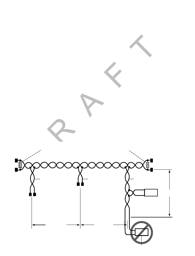
80-J9968-1 Rev. A MAY CONTAIN U.S. AND INTERNATIONAL EXPORT CONTROLLED INFORMATION 11-3
Vehicle Data Bus Connections Vehicle Data Source Selection
DO N OT
COPY
Vehicle Data Source Selection
When making data source connections, there are two possible data buses available: the
J1708 /J1587 low-speed data bus and the J1939 high-speed data bus. The truck year, make,
and model, as well as the Qualcomm applications used determine which data bus to use.
If you do not know which data source to use, contact your Qualcomm representative for
assistance.
Guidelines for Connecting to the J1939 Data Bus
• The MCP200 has two J1939 CAN inputs. Choose Option 1 or Option 2 according to these
specifications:
-Option 1: CAN 1 is used for all after market installations and some factory prewired
installations when the distance between the MAS200 and the J1939 bus connection
point exceeds 10 feet.
-Option 2: CAN0 is only used for factory prewired installations when the distance
between the MAS200 and the J1939 bus connection point does not exceed 10 feet.
• DO NOT extend factory wires.
• Maximum stub length is 10 feet.
• Minimum stub spacing is 4 inches.
• Never have more than one ECM device on the same stub.
Termination Resistors at Ends of the Main Backbone
Each 120 Ohms 5 % 1/4W
CAN_H
CAN_L
To ECM
08AAA_053Dem
Stub StubStub
4 in Min 4 in Min
10 ft. Max
ECM
Device
Never have more than
one ECM on the same stub
Reads 60 ohms when measured in parallel from CAN_HIGH to CAN_LOW
ECM
Device
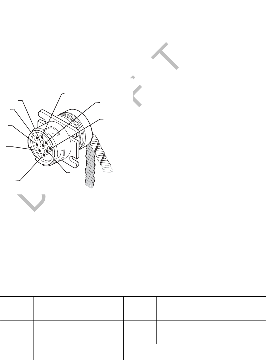
J1939 Pre-installation Check Out Vehicle Data Bus Connections
11-4 MAY CONTAIN U.S. AND INTERNATIONAL EXPORT CONTROLLED INFORMATION 80-J9968-1 Rev. A
DO NOT COPY
J1939 Pre-installation Check Out
Prior to beginning any installation, start the vehicle and verify that the vehicle is in good
working order, has no faults, and no check engine lights display.
Resistance Test (to Verify that J1939 Is Present)
1. Turn ignition OFF.
2. Verify that J1939 is present on vehicle. Locate the 9-pin diagnostic (Deutsch) connector.
Note
If you have a 6-pin connector, you have J1708/J1587 only. See Connecting J1708 /
J1587 on page 11-10.
3. Using an ohmmeter, place the positive lead on pin C and the negative lead on pin D of
the diagnostic connector. Verify that the resistance is 55–65 ohms.
• If the resistance is 55–65 ohms, J1939 is present. Go to Checking the MCP200
Accessory Cable for CAN0 and CAN1 on page 11-5.
• If the resistance is not 55–65 ohms, there is a problem with your J1939 data bus. Fix
the problem.
Note
On some vehicles, open doors and/or cabin lights on may cause CAN/J1939 bus
activity which may interfere with diagnostic connector resistance measurements.
Pin C CAN High (tractor bus) Pin H Proprietary OEM use/
Implement bus CAN High
Pin D CAN Low (tractor bus) Pin J Proprietary OEM use/
Implement bus CAN Low
Pin E CAN Shield (J1939-11)
08AAA_051A
A
PIN C
CAN_HIGH
B
F
E
J
G
H
PIN D
CAN_LOW
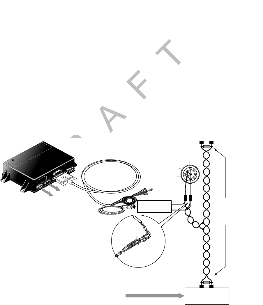
80-J9968-1 Rev. A MAY CONTAIN U.S. AND INTERNATIONAL EXPORT CONTROLLED INFORMATION 11-5
Vehicle Data Bus Connections Checking the MCP200 Accessory Cable for CAN0 and CAN1
DO N OT
COPY
Checking the MCP200 Accessory Cable for CAN0 and CAN1
1. Locate the end of the installed MCP200 accessory cable. This cable is usually located
in either the vehicle’s dash or B-pillar.
2. Locate the CAN connector on the accessory cable. The CAN connector is marked
either CAN0 or CAN1 to identify the MAS200 CAN port being used.
• All after-market installations have a CAN1 connector.
• OEM prewires can have either a CAN0 or a CAN1 connector, depending on the
truck model/manufacturer.
3. For a CAN1 connector, go to Option 1—Connecting J1939 Using CAN 1 (for All After-
Market Installations) on page 11-5.
4. For a CAN0 connector, go to Option 2—Connecting J1939 Using CAN0 (for Most OEM
Prewires) on page 11-8.
Option 1—Connecting J1939 Using CAN 1 (for All After-Market Installations)
Connect the MCP200 accessory cable to the CAN converter. A CAN converter cable is
required for this procedure (see Appendix A for detailed pin and wire callouts of the CAN
converter cable).
In order for the MCP200 to receive J1939 data, the MAS200 CAN/J1939 wires must be
connected to the truck’s J1939 CAN bus in the vehicle.
Follow all SAE guidelines when connecting to the vehicle’s J1939 data bus.
Mobile Application Server
(MAS)
CONVERTER
To Modem
To Display
J1939+
Ye l l o w
J1939-
Green
J1939+
J1939-
MCP
Accessory Cable
Accessory
Cable
D
E
F
G
H
J
B
CA
CAN_H
CAN_L
Termination resistors
at the far ENDS of
the Main Backbone
Each120 Ohms 5% 1/4W
TRUCK ECM
Most US ECMs are
hi impedance (Z)
and not internally terminated
PIN C
CAN_HIGH
PIN D
CAN_LOW
Diagnostic
Connector

Making the Connection Vehicle Data Bus Connections
11-6 MAY CONTAIN U.S. AND INTERNATIONAL EXPORT CONTROLLED INFORMATION 80-J9968-1 Rev. A
DO NOT COPY
Making the Connection
1. Start the vehicle and verify that the truck is in good working order and displays no dash
faults.
2. Turn OFF the truck and ensure that no dash lights are on.
Note
Some trucks may have activity on the J1939 bus with the door open or if an accessory is
active. This can cause a faulty resistance reading on the CAN bus.
3. Measure the J1939 bus resistance at the diagnostic connector. It should read 60 ohms.
(Refer to Resistance Test (to Verify that J1939 Is Present) on page 11-4.)
4. Locate the J1939 bus wires.
• The J1939 wires are a twisted pair
• CAN high (J1939+) (yellow)
• CAN low (J1939-) (green)
5. Determine a suitable J1939 location point. In many vehicles you can connect behind the
truck diagnostic connector. Be aware that only one electronic device should be
connected to the J1939 stub at the back of the diagnostic connector at a time. If another
device is already present you will need to splice directly into the vehicle's backbone.
Contact Qualcomm Enterprise Services (QESSM) Customer Support for assistance if
needed.
6. Splice the yellow CAN high J1939+ wire from the converter cable to the yellow CAN
high J1939+ wire from the truck’s J1939 bus. (Refer to the illustration on page 11-5.)
7. Splice the green CAN low J1939- wire from the converter cable to the green CAN low
J1939- wire from the truck’s J1939 bus. (Refer to the illustration on page 11-5.)
8. Measure the J1939 bus resistance at the diagnostic connector. It should read 60 ohms.
9. Locate the CAN1 4-pin Molex connector on the MCP200 accessory cable.
J1939+
Ye l l o w
J1939-
Green
J1939+
J1939-
08AAA_048
B
J1939
Converter cable
Truck's
J1939 bus
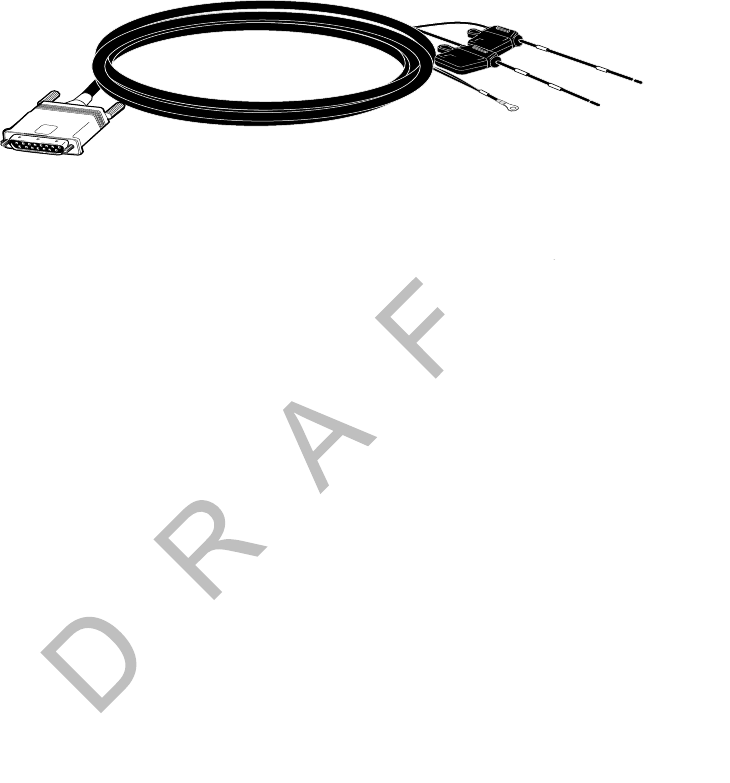
80-J9968-1 Rev. A MAY CONTAIN U.S. AND INTERNATIONAL EXPORT CONTROLLED INFORMATION 11-7
Vehicle Data Bus Connections Making the Connection
DO N OT
COPY
10. Connect the CAN converter cable to the CAN1 Molex plug on the MCP200 accessory
cable.
11. Start the vehicle and verify that the truck is in good working order and displays no dash
faults.
12. Verify that the J1939 data is being passed to the MAS200 from the data bus by
monitoring the VDS screen on the MAS200. (Refer to Verifying Data Source
Connectivity on page 11-11.)
13. Stow and secure any loose wires, making sure to keep the wires clear of sharp edges
and away from panels and moving parts.
09AAA_02
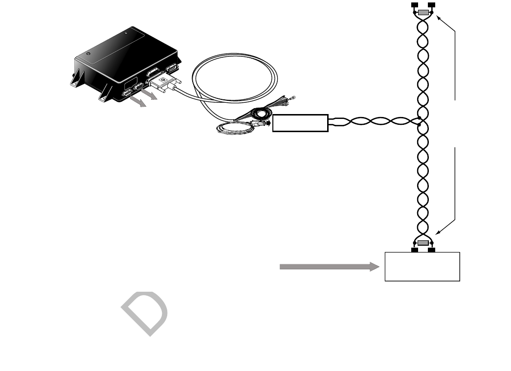
Option 2—Connecting J1939 Using CAN0 (for Most OEM Prewires) Vehicle Data Bus Connections
11-8 MAY CONTAIN U.S. AND INTERNATIONAL EXPORT CONTROLLED INFORMATION 80-J9968-1 Rev. A
DO NOT COPY
Option 2—Connecting J1939 Using CAN0 (for Most OEM Prewires)
Connect the MCP200 accessory cable to the OEM-supplied stub connector. A CAN converter
cable is not required for this procedure.
In order for the MCP200 to receive J1939 data, the MAS200 CAN/J1939 wires must be
connected to the truck’s J1939 CAN bus in the vehicle.
Follow all SAE guidelines when connecting to the J1939 data source.
Note
If you are doing an installation on an OEM prewired truck with a CAN1 MCP200 accessory
cable and a converter cable is not included as part of the prewire, go to Option 1—Connecting
J1939 Using CAN 1 (for All After-Market Installations) on page 11-5.
CAN_HCAN_L
Termination Resistors
at the far ENDS
of the Main Backbone
Each120 Ohms 5% 1/4W
08AAA_046A
OEM
CONNECTOR
TRUCK ECM
Most US ECMs are
hi impedance (Z)
and not internally terminated
Mobile Application Server
(MAS)
Accessory
Cable
To Modem
To Display
Stub

80-J9968-1 Rev. A MAY CONTAIN U.S. AND INTERNATIONAL EXPORT CONTROLLED INFORMATION 11-9
Vehicle Data Bus Connections Making the Connection
DO N OT
COPY
Making the Connection
1. Start the vehicle and verify that the truck is in good working order and displays no dash
faults.
2. Turn OFF the truck and ensure that no dash lights are on.
3. Measure the J1939 bus resistance at the diagnostic connector. It should read 60 ohms.
Note
Some trucks may have activity on the J1939 bus with the door open or if an accessory
is active. This can cause a faulty resistance reading on the CAN bus.
4. Locate the OEM J1939 stub connector and the CAN0 mating connector on the MCP200
accessory cable. These are usually located either in the truck’s B pillar or in the center
of the dash.
5. Connect the two J1939 connectors.
6. Measure the J1939 bus resistance at the diagnostic connector. It should read 60 ohms.
7. Start the vehicle and verify that the truck is in good working order and displays no dash
faults.
8. Verify that the J1939 data is being passed to the MAS200 from the data bus by
monitoring the VDS screen on the MAS200. (Refer to Verifying Data Source
Connectivity on page 11-11.)
9. Stow and secure any loose wires, making sure to keep the wires clear of sharp edges
and away from panels and moving parts.
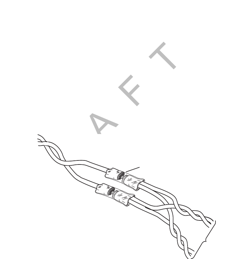
Connecting J1708 /J1587 Vehicle Data Bus Connections
11-10 MAY CONTAIN U.S. AND INTERNATIONAL EXPORT CONTROLLED INFORMATION 80-J9968-1 Rev. A
DO NOT COPY
Connecting J1708 /J1587
1. Start the vehicle and verify that the truck is in good working order and displays no dash
faults.
2. Verify that the engine ignition switch is OFF.
3. Locate the engine data diagnostic connector.
• The data source wires to the engine data diagnostic connector are a twisted pair that
should remain twisted after the installation is complete.
• Consult the manufacturer’s wiring diagrams to identify the wires (some are marked
DATA+ and DATA- or D/L+ and D/L-, and some are marked with numbers or colors).
• Note which wire is plus (+) and which is minus (-).
• To avoid confusion, cut and splice the positive wires first and then the negative wires.
Because there usually is not much slack in the engine data diagnostic connector
wires, be careful in cutting and splicing to them.
4. Splice the brown J1708+ wire from the accessory cable to the DATA+ (pin F) wire of the
engine diagnostic connector. Reconnect the wires.
5. Splice the red J1708- wire from the accessory cable to the DATA- (pin G) wire of the
engine diagnostic connector.
6. Start the vehicle and verify that the truck is in good working order and displays no dash
faults.
7. Go to Verifying Data Source Connectivity on page 11-11.
8. Stow and secure any loose wires, making sure to keep the wires clear of sharp edges
and away from panels and moving parts such as throttle and brake linkage.
• Dress any bare-ended wires to prevent a short.
• Maintain wire twists as close to the splice as possible.
MCP
Accessory Cable
Butt Splice
Data Link-
Data Link-
Data Link+
Data Link+
To vehicle
datalink
J1708-
J1708+
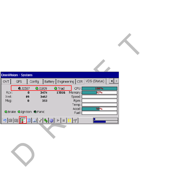
80-J9968-1 Rev. A MAY CONTAIN U.S. AND INTERNATIONAL EXPORT CONTROLLED INFORMATION 11-11
Vehicle Data Bus Connections Verifying Data Source Connectivity
DO N OT
COPY
Verifying Data Source Connectivity
1. Turn ignition ON.
2. Verifying Data Bus Connectivity
Check the VDS (Status) screen and verify that the MAS200 is enabled for J1939,
J1708, and/or traditional sensors.
• The light indicator will be green when a data source is enabled to receive data from
that source.
• Data source must be active to increment data.
If you have any questions, contact QES Customer Support.
Black: Not Configured/No Data; Green: Active Data; Red: Stale Data.
Note
Press the Green Light/Red Light icon located along the bottom of the screen to
display the VDS Summary screen and note the data source and LED status.
If data is not being passed, debug.
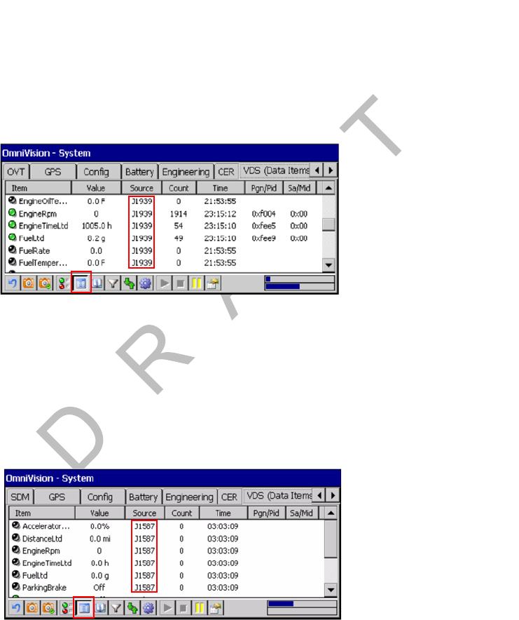
Verifying Data Source Connectivity Vehicle Data Bus Connections
11-12 MAY CONTAIN U.S. AND INTERNATIONAL EXPORT CONTROLLED INFORMATION 80-J9968-1 Rev. A
DO NOT COPY
3. Verify Data Source
a. Verifying J1939 Data Is Present
Verify the following data fields are showing green and incrementing to confirm that
J1939 data is present:
• Speed RPM
• Parking Brake Accelerator
• Distance LTD Fuel LTD
• Engine Time LTD
Note
Press the VDS Details icon located along the bottom of the screen to display the VDS
Details screen and note the data source.
b. Verifying J1587/J1708 Data Is Present
Verify the J1587/J1708 data fields are showing green and incrementing to confirm that
J1587/J1708 data is present.
Note
Press the VDS Details icon located along the bottom of the screen to display the VDS
Details screen and note the data source.

80-J9968-1 Rev. A MAY CONTAIN U.S. AND INTERNATIONAL EXPORT CONTROLLED INFORMATION 12-1
DO NOT COPY
12
System Verification
Topics in this chapter provide information and procedures for performing a basic system
verification:
What Is Basic Qualcomm® MCP200 System Verification? . . . . . . . . . . . . . . . . . . 12-2
MCP200 Display Unit Screens. . . . . . . . . . . . . . . . . . . . . . . . . . . . . . . . . . . . . . . . 12-2
Flowchart—Basic MCP200 System Verification . . . . . . . . . . . . . . . . . . . . . . . . . 12-12
Basic MCP System Verification Procedure . . . . . . . . . . . . . . . . . . . . . . . . . . . . . 12-14
Qualcomm® MCP System Verification Form. . . . . . . . . . . . . . . . . . . . . . . . . . . . 12-18
For technical questions, contact Qualcomm Enterprise Services (QESSM) Customer Support.
Customer Support is staffed 24 hours a day, 365 days a year:
In the United States, call 800-541-7490
In Canada, call 800-863-9191
For verifying the SensorTRACS® system, the TrailerTRACS® system, and other accessories,
see the appropriate chapter in this manual.
Note
GPS is required for both satellite and terrestrial networks.
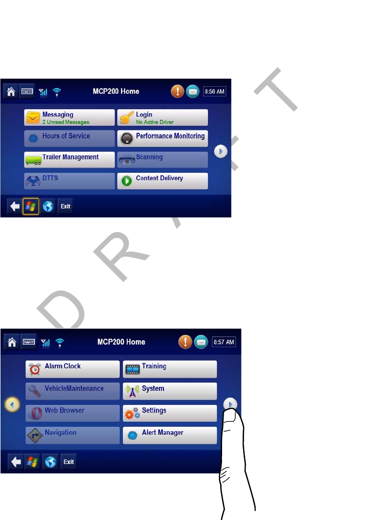
What Is Basic Qualcomm® MCP200 System Verification? System Verification
12-2 MAY CONTAIN U.S. AND INTERNATIONAL EXPORT CONTROLLED INFORMATION 80-J9968-1 Rev. A
DO NOT COPY
What Is Basic Qualcomm® MCP200 System Verification?
• A functional system check that should be performed after installation or service to verify
that the MCP200 is operating properly.
MCP200 Display Unit Screens
• Shortly after you power up the MCP200, the Qualcomm® MCP200 Home screen displays.
• Tap the different buttons to access information.
• Before you perform the system verification procedure, you may find it helpful to become
familiar with the commonly used display unit screens.
• System verification information has been stored on screens/buttons under the System
button.
• Scroll down to the System button and tap the button to access the display screens shown
on the following pages.
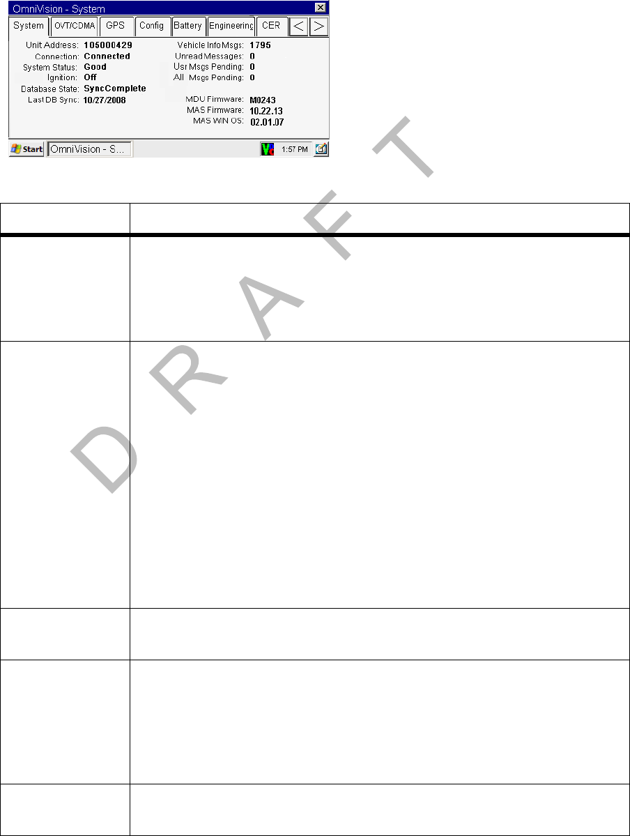
80-J9968-1 Rev. A MAY CONTAIN U.S. AND INTERNATIONAL EXPORT CONTROLLED INFORMATION 12-3
System Verification MCP200 System Screen
DO N OT
COPY
MCP200 System Screen
• Tap the System button to access system information about the MCP200.
Field Description
Unit Address • Also called the UNIT SERIAL NUMBER.
• Shows the mobile unit (MCP200) ID, e.g., 105000xxx.
• Tells the dispatcher the correct address for sending messages to the
vehicle.
• If the MCP200 is replaced, this field will display a different address.
Connection • Indicates whether the link within the terrestrial data modem (TDM) is
communicating properly.
• Indicates whether the link within the satellite data modem (SDM) is
communicating properly.
System Status Indicates the MCP200’s operational status:
• Good is displayed if the MCP200 is operating properly.
• A numerical error code (e.g., 10000) is displayed if the MCP200
detects a problem.
• Refer to the appropriate section in the Qualcomm® MCP 200 Series
and Accessory Diagnostic Guide for troubleshooting procedures.
• If you are using the optional SDM, Quiet is displayed within seconds
after you turn the ignition OFF.
Ignition • Ignition Off is displayed within seconds after you turn the ignition
OFF.
Database State Indicates the MCP200’s database status:
• SyncComplete is displayed if customer and mobile unit (MCP200)
information has been received by the MCP200 and is up-to-date. This
is the desired state.
• Out of Sync is displayed if the mobile unit (MCP200) information has
not been received by the MCP200 and is waiting to be updated.
Last DB Sync Indicates the date of the most recent SyncComplete status for the
MCP200.
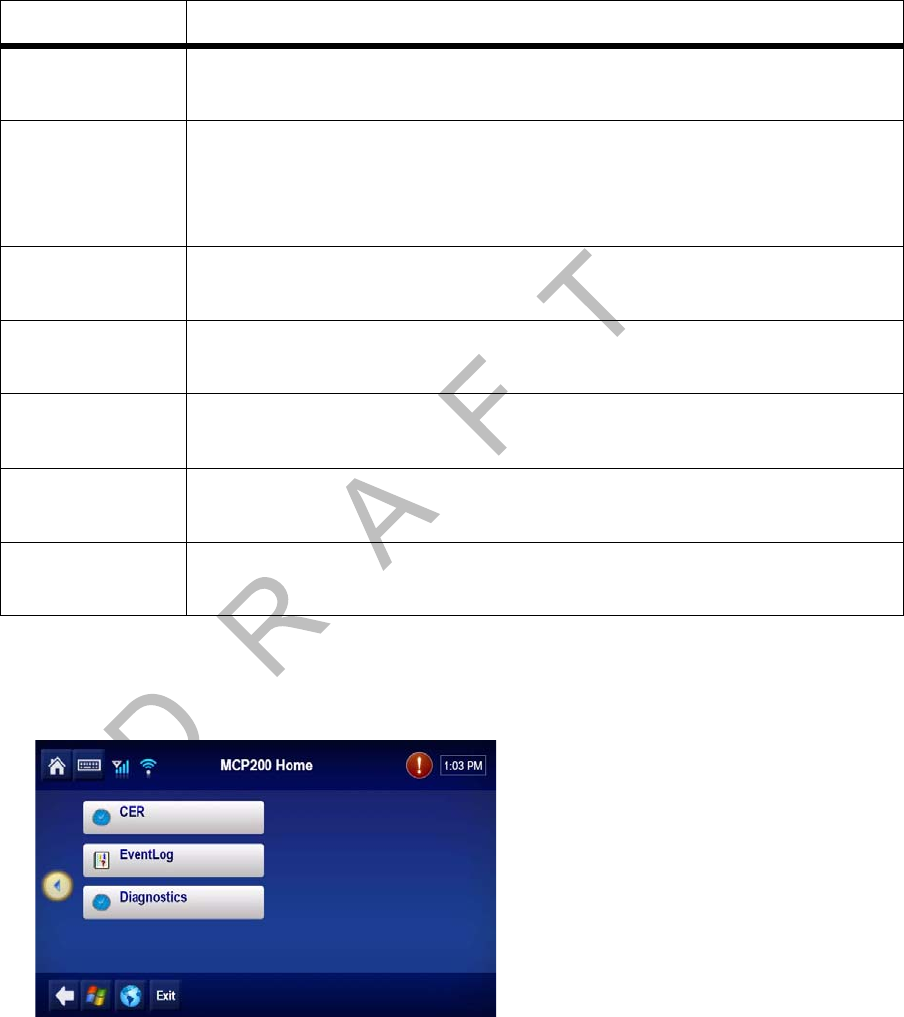
MCP200 Diagnostic Screen System Verification
12-4 MAY CONTAIN U.S. AND INTERNATIONAL EXPORT CONTROLLED INFORMATION 80-J9968-1 Rev. A
DO NOT COPY
MCP200 Diagnostic Screen
• Tap the Diagnostics button to access diagnostic information about the MCP200.
• Run Test All.
Vehicle Info
Msgs Indicates the total number of messages the MCP200 has received from
the electronic control module (ECM) since the ignition was turned ON.
Unread
Messages • Indicates the number of messages the MCP200 has received but that
have not been read.
• This number increases as the MCP200 receives new messages, and
decreases as they are read.
Usr Msgs
Pending Indicates the number of text messages the MCP200 has in the queue to
be sent.
All Msgs
Pending Indicates the total number of all messages the MCP200 is currently
sending.
MDU Firmware Indicates the software version currently installed on the display
interface unit 200 (DIU200).
MAS Firmware Indicates the software version currently installed on the mobile
application server 200 (MAS200), e.g., 10.22.13.
MAS WIN OS Indicates the Windows operating system currently installed on the
MAS200.
Field Description
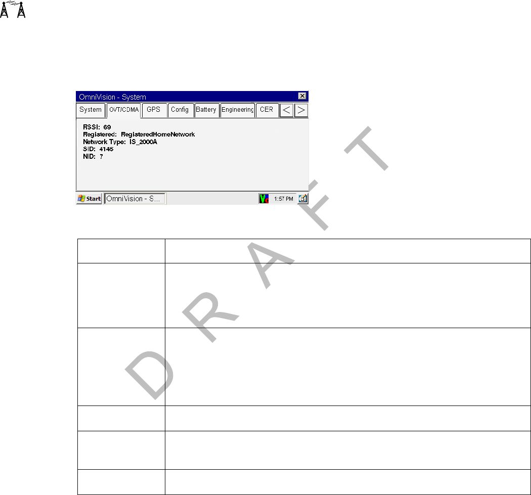
80-J9968-1 Rev. A MAY CONTAIN U.S. AND INTERNATIONAL EXPORT CONTROLLED INFORMATION 12-5
System Verification MCP200 OVT/CDMA Screens
DO N OT
COPY
MCP200 OVT/CDMA Screens
• Tap the OVT/CDMA button to access antenna information about the MCP200, such as
signal strength.
• There are five OVT/CDMA screens, which you navigate by tapping the screen and then
using the arrow keys to move from screen to screen.
Field Description
RSSI • Received Signal Strength Indication—The strength of a wireless
communication network signal being received by the antenna during
forward link acquisition to the wireless network provider.
• RSSI should be less than 100.
Registered • MCP200 terrestrial system checks network coverage every 3 minutes.
• If the unit is within the RegisterdHomeNetwork, it is in home network
coverage.
• If the unit is RegisteredRoaming, it is either roaming to find the home
network or roaming to find another network.
Network Type IS2000A.
SID System Identification Number—The number that allows the unit to
quickly register on the cellular network.
NID Network Identification Number.
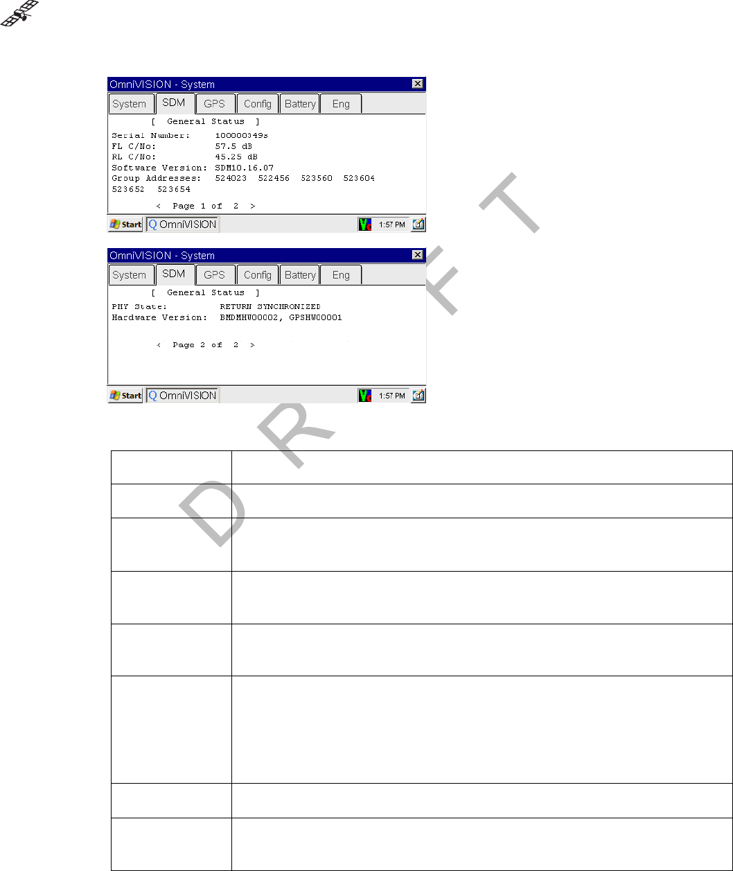
MCP200 SDM Screens System Verification
12-6 MAY CONTAIN U.S. AND INTERNATIONAL EXPORT CONTROLLED INFORMATION 80-J9968-1 Rev. A
DO NOT COPY
MCP200 SDM Screens
• Tap the SDM button to access antenna information about the MCP200, such as signal
strength.
Field Description
Serial Number The serial number of the SDM.
FL C/No • Signal strength received from the data satellite (the forward signal).
• Typically, values should be greater than 50.
RL C/No • Signal strength received from the MCP200 (the return signal).
• Typically, values should be greater than 33.
Software
Version Indicates the firmware version currently installed on the SDM.
Group
Addresses • Shows the group ID to which the MCP200 is assigned.
• Also shows the number of other groups, which the MCP200 is a
member.
• Numbers are defined and used by the dispatcher to address the fleet
or groups of MCP200s.
PHY State Indicates the physical state of the antenna.
Hardware
Version Indicates the SDM hardware version.
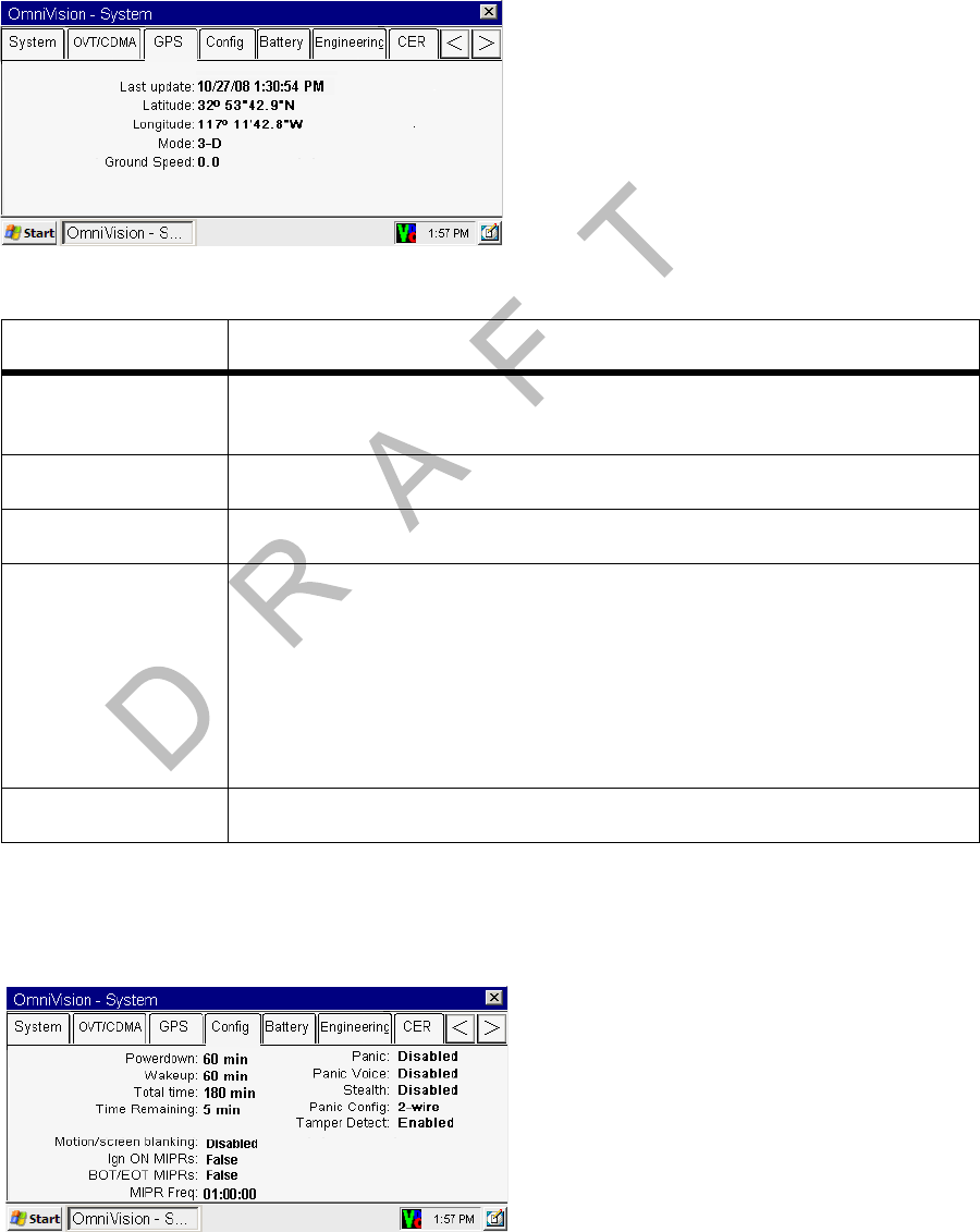
80-J9968-1 Rev. A MAY CONTAIN U.S. AND INTERNATIONAL EXPORT CONTROLLED INFORMATION 12-7
System Verification MCP200 GPS Screen
DO N OT
COPY
MCP200 GPS Screen
• Tap the GPS button whenever you want to see basic GPS information.
MCP200 Config Screen
• Tap the Config button whenever you want to see the basic configuration of the unit.
Field Description
Last update • The time of the last GPS update.
• This value should update every second.
Latitude The last received latitude value.
Longitude The last received longitude value.
Mode Indicates the MCP200’s GPS status:
•3-D is displayed if the receiver is able to view three or more GPS
satellites. Under normal performance, a 3-D mode will be
displayed.
• 2-D is displayed if the receiver is able to calculate a position, but
has a limited view to the GPS satellites.
• NO FIX is displayed when the GPS satellites cannot be viewed.
Ground Speed Speed calculated by GPS through a change in vehicle location.

MCP200 Engineering Screen System Verification
12-8 MAY CONTAIN U.S. AND INTERNATIONAL EXPORT CONTROLLED INFORMATION 80-J9968-1 Rev. A
DO NOT COPY
MCP200 Engineering Screen
• This screen is for engineering purposes only.
Field Description
Powerdown • Number of minutes after ignition is turned OFF when the MCP 200
will go into sleep mode.
• Configured by dispatch.
Wakeup • The frequency the MCP200 wakes up from sleep mode to check
for dispatch messages.
• Configured by dispatch.
Total Time • Number of minutes the MCP200 draws power from the vehicle
battery with the ignition OFF.
• Configured by dispatch.
Time Remaining Number of minutes before the MCP200 goes into sleep mode.
Motion/screen
Blanking • Indicates if the display screen will be active when motion is
detected (shown as Disabled or BlankEntireScreen).
• Configured by dispatch.
Ign ON MIPRs Indicates if a mobile-initiated position report will be sent when ignition
is turned ON.
BOT/EOT MIPRs Indicates if beginning of trip and end of trip mobile-initiated position
reports will be sent.
MIPR Freq Indicates the frequency (HH:MM:SS) of mobile-initiated position
reports.
Panic Indicates whether the panic button/message feature is enabled.
Panic Voice Indicates if an audio message will be played (TTS) when a panic
button press is detected.
Stealth Indicates whether panic messages will show in the messaging
Outbox.
Panic Config Indicates how hardware needs to be connected for panic button
presses to be detected.
Tamper Detect Indicates if the MCP is enabled or disabled for tamper detection.
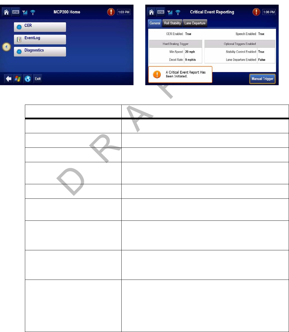
80-J9968-1 Rev. A MAY CONTAIN U.S. AND INTERNATIONAL EXPORT CONTROLLED INFORMATION 12-9
System Verification MCP200 CER Screen
DO N OT
COPY
MCP200 CER Screen
• Tap the CER button to access the screen that captures and reports critical event
information, such as hard braking, vehicle speed, location, stability control (VDC), and
panic button events, to the customer before and after the event occurs.
Field Value
CER Enabled/disabled If enabled, the MCP200 captures CER events.
Speech Enabled/disabled If enabled, what is printed in the alert pop-ups is spoken.
Hard Braking Minimum Speed Speed at which mobile unit detects hard brake events.
Hard Braking Deceleration Rate The rate of deceleration that triggers a hard brake event
(Default = 9 MPH/SEC).
VDC Enabled/disabled Stability control is enabled/disabled.
VDC Minimum Speed Minimum speed at which mobile unit detects VDC
messages.
VDC On Threshold Number of ATC (PID hex value is 97) “on” messages that
must be seen in a row before a VDC event is considered
to be in progress.
VDC Off Threshold Number of ATC (PID hex value is 97) “off” messages that
must be seen in a row before a VDC event is considered
to have ended.
VDC Bits Tracked Setting that determines which bits the mobile unit tracks
to monitor stability control events:
•Brake bits only
• Engine bits only
• Brake or Engine bits (Default)
• Brake and Engine bits
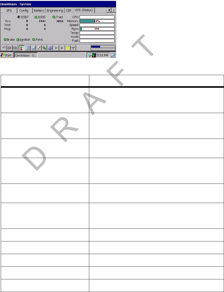
VDS (Status) Screen System Verification
12-10 MAY CONTAIN U.S. AND INTERNATIONAL EXPORT CONTROLLED INFORMATION 80-J9968-1 Rev. A
DO NOT COPY
VDS (Status) Screen
• Access vehicle data services (VDS) information, by using the scroll bar and tapping the
VDS (Status) button.
Field Value
J1587 If vehicle is configured to receive data, the light is
green if the vehicle is receiving data from the J1587
data source.
J1939 If vehicle is configured to receive data, the light is
green if the vehicle is receiving data from the J1939
data source.
Trad The PTO, which is always active (the light is always
green).
RCV • These are the packets of data being received on
the data bus.
• Value should be constantly increasing.
Xmt Packets of data being received on the data bus as
requested (transmitted) packets.
Msg Packets of data being received on the data bus that
are of longer length than the normal data packet
size.
Brake Brake light is green if the parking brake is engaged.
Ignition Ignition light is green if the ignition is ON.
Panic Panic light is green if PANIC is enabled.
CPU Shows MAS usage.
Memory Amount of memory used.

80-J9968-1 Rev. A MAY CONTAIN U.S. AND INTERNATIONAL EXPORT CONTROLLED INFORMATION 12-11
System Verification VDS (Status) Screen
DO N OT
COPY
Speed Speed of the vehicle.
Rpm RPM of the vehicle.
Temp Oil temperature.
Accel Acceleration (throttle position) percentage.
Fuel Life-to-date (LTD) fuel.
Field Value

Flowchart—Basic MCP200 System Verification System Verification
12-12 MAY CONTAIN U.S. AND INTERNATIONAL EXPORT CONTROLLED INFORMATION 80-J9968-1 Rev. A
DO NOT COPY
Flowchart—Basic MCP200 System Verification
Turn ignition
ON
Step 2
Yes
Move unit to
acquire
network
signal
Step 1
System_Flow_1_MCP200
Step 3
Does
DIU light up
& display characters?
Do backlight, volume,
and brightness
work?
See Chapter 5
in the
MCP200 Series
Diagnostic Guide
No
All tests passsed
Status: #### See appropriate
chapter in the
MCP200 Series
Diagnostic Guide
Display
System screen.
Does Status display
numerical code
or Good?
Step 5
OFF
within 10 minutes
Step 4
See appropriate
chapter in the
MCP200 Series
Diagnostic Guide
Display
Diagnostics screen.
Run all tests.
Some/all
tests failed
Step 7
Was message
acknowledged
by dispatcher?
Step 6
Display
Message screen.
Send test message
to dispatcher
Step 8
Have dispatcher
send test
message to
MCP200
No
Yes
Step 9
See Chapter 7
in the
MCP200 Series
Diagnostic Guide
Was test
message received
at MCP200?
No
Yes
Go to Step 10
See Chapter 7
in the
MCP200 Series
Diagnostic Guide

80-J9968-1 Rev. A MAY CONTAIN U.S. AND INTERNATIONAL EXPORT CONTROLLED INFORMATION 12-13
System Verification Flowchart—Basic MCP200 System Verification
DO N OT
COPY
System_Flow_2_MCP200
Verification
complete
For verification procedures
for optional accessories,
see the appropriate chapter.
System OK
Yes
Step 12
Turn ignition
OFF
Step 10
See Chapter 7
in the
MCP200 Series
Diagnostic Guide
Was test
message received
at MCP200?
No
Yes
Yes
Step 11
See Chapter 15
in the
MCP200 Series
Diagnostic Guide
Can you play
message with
RCD?
No
Does DIU200
stay on with
ignition OFF?
See Chapter 11
in the
MCP200 Series
Diagnostic Guide
Step 13
No
Yes
Yes
Does
Status
change to Ignition Off
within 10
minutes?
Step 14
No See Chapter 12
in the
MCP200 Series
Diagnostic Guide
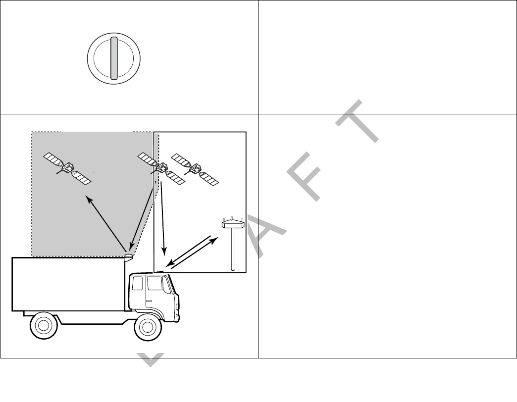
Basic MCP System Verification Procedure System Verification
12-14 MAY CONTAIN U.S. AND INTERNATIONAL EXPORT CONTROLLED INFORMATION 80-J9968-1 Rev. A
DO NOT COPY
Basic MCP System Verification Procedure
The steps in this procedure match the steps on the
flowcharts on the previous pages. The steps are not
always sequential—you may be instructed to skip
steps.
1. Turn the vehicle ignition ON; the engine does
not have to be running.
2. Make sure the vehicle is in a good location.
• The vehicle should be in a location where
the antenna is able to acquire a wireless
communication network signal.
Additionally, a clear view of the sky is
needed for GPS when the unit is brought
on the air for the first time, or after any
reset.
• If you are using an SDM with the MCP200,
the SDM should have a clear view of the
satellite which is located above the
equator, roughly south of Georgia.
A
C
C
O
F
F
O
N
S
T
A
R
T
Turn the ignition ON
OM/E-0128-031TQMCP
GPS
Satellites
PCS
To w e r
Data
Satellite
Satellite Terrestrial
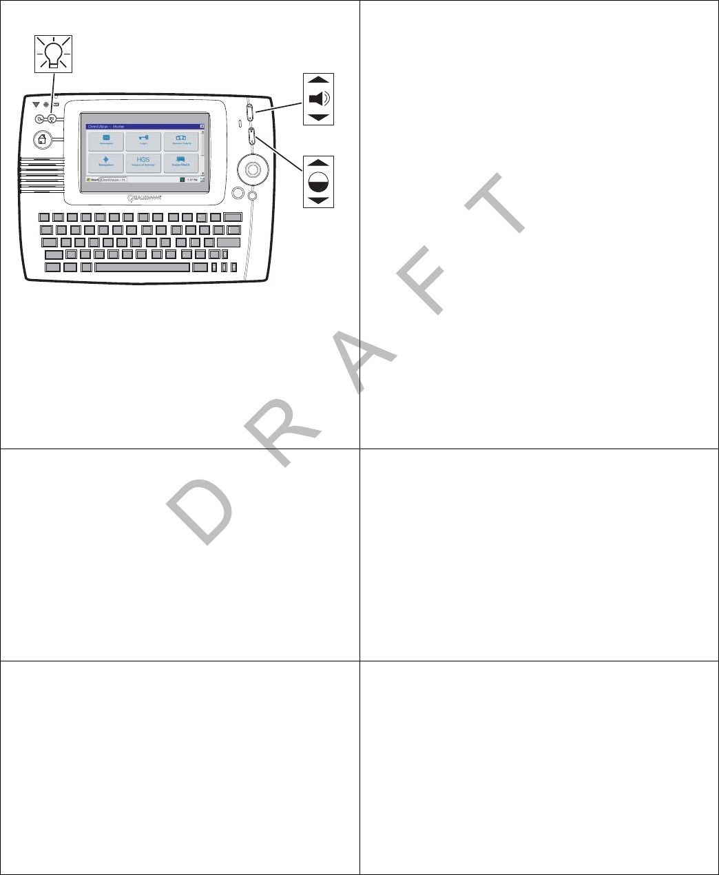
80-J9968-1 Rev. A MAY CONTAIN U.S. AND INTERNATIONAL EXPORT CONTROLLED INFORMATION 12-15
System Verification Basic MCP System Verification Procedure
DO N OT
COPY
3. Check the display unit and verify that the
screen lights up and displays characters; and
that the backlight, brightness, and volume
controls work correctly.
The BACKLIGHT key turns the display unit
backlight ON and OFF.
The BRIGHTNESS key adjusts the brightness
of the display window; press the top of this
key to lighten the display window or the
bottom to darken the display window.
The VOLUME CONTROL key adjusts the
volume of the DIU200 speaker. Press the top
of this key to increase the volume or the
bottom of the key to decrease the volume.
• If the screen displays characters, and the
controls work correctly, go to step 4.
• If the screen is dark, or the controls do not
work correctly, perform the diagnostic
procedure in Chapter 5 in the Qualcomm®
MCP200 Series and Accessory Diagnostic
Guide.
4. Go to the Home screen and tap the System
button. Tap the System button.
Check the System Status field and verify that
the Status is Good.
• If the Status is Good, go to step 5.
• If the Status is a numerical value, go to the
appropriate diagnostic procedure for that
value in the Qualcomm® MCP200 Series
and Accessory Diagnostic Guide.
5. Go to the Home screen and tap the
Diagnostics button.
Run all diagnostics’ tests.
• If the MCP200 passed all the tests, go to
step 6.
• If the MCP200 failed any of the tests, go to
the appropriate diagnostic procedure for
the failed item in the Qualcomm® MCP200
Series and Accessory Diagnostic Guide.
Esc
1
!
2
@
3
#
4
$
5
%
6
^
7
&
8
*
9
(
0
)
=
Backspace
+
Tab
Q
Caps
0WE R T Y U I P
{
[
{
[
Enter
Shift
Ctrl Alt Sym
Delete
Shift
LKJHGFDSA "
'
MN
BVC
XZ
V
V
?
!
Opt
Back
05AAA_215B
Volume
Control
Backlight
Toggle
Backlight
Control
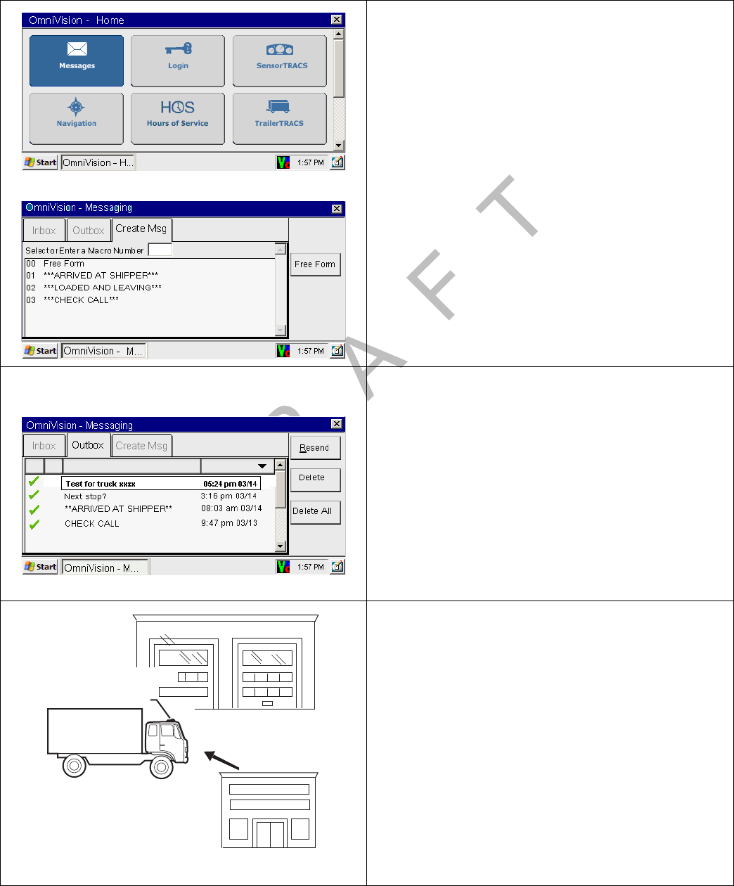
Basic MCP System Verification Procedure System Verification
12-16 MAY CONTAIN U.S. AND INTERNATIONAL EXPORT CONTROLLED INFORMATION 80-J9968-1 Rev. A
DO NOT COPY
6. Send a test message to the dispatcher. Go to
the Home screen and tap the Messages
button.
• Tap the Create Msg button.
• Tap the Free Form button.
• Type the message text including the truck
number.
• Tap the SEND button.
• Tap Yes to send the message.
7. Tap the Outbox button to display the
message that was just sent. Orange arrows
indicate the message is in transit; a green “”
(check mark) indicates the message has been
acknowledged.
• If the message is acknowledged, go to step
8.
• If the message is not acknowledged,
perform the diagnostic procedure in
Chapter 7 in the Qualcomm® MCP200
Series and Accessory Diagnostic Guide.
8. Have the dispatcher send a test message to
the MCP. If the dispatcher is not available, call
QES Customer Support (800-541-7490) to
have the message sent.
If the Remote Message Waiting Light or
Message Waiting Buzzer feature is installed,
you can also test them at this time by having
an Important or Sleepy Important message
sent.
Contact the Dispatch
Center and have the
dispatcher send a test
message to the MCP
Dispatch
Center
Terrestrial
Antenna
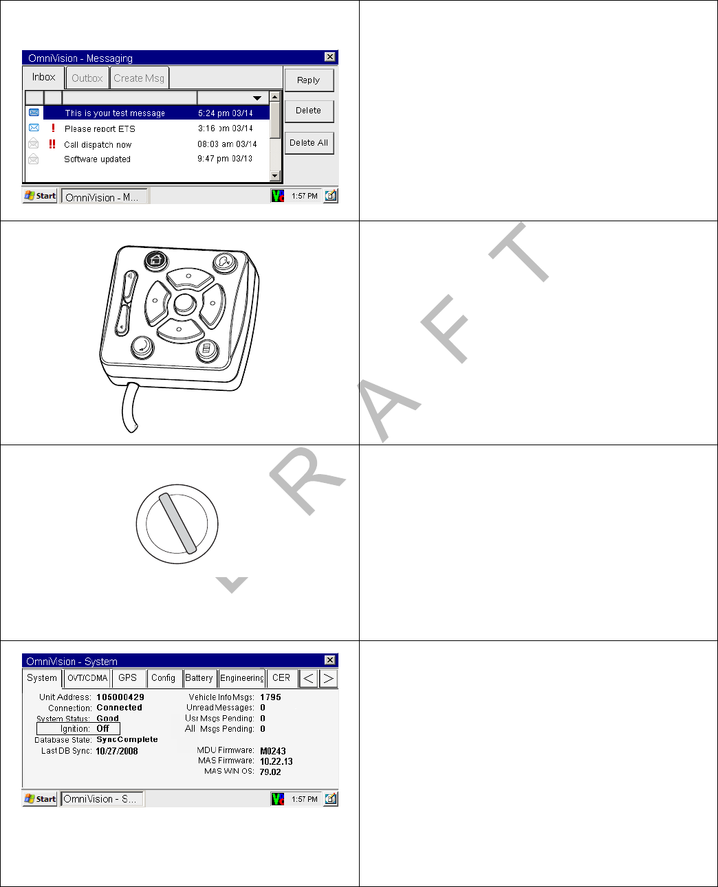
80-J9968-1 Rev. A MAY CONTAIN U.S. AND INTERNATIONAL EXPORT CONTROLLED INFORMATION 12-17
System Verification Basic MCP System Verification Procedure
DO N OT
COPY
For verifying the SensorTRACS system, the TrailerTRACS system, and other accessories,
see the appropriate chapter in this manual.
9. After a few minutes, the unit should chirp, the
Message Waiting Light should come on, and a
voice notification will tell you the message has
been received. Tap the Inbox button to
display the dispatcher’s message.
• If the MCP received the message, go to
step 10.
• If the MCP did not receive the message,
perform the diagnostic procedure in
Chapter 7 in the Qualcomm® MCP200
Series and Accessory Diagnostic Guide.
10. Verify that the message can be played by
pressing the TTS key using the Omni keys on
the DIU200.
• If the message can be played using the
Omni keys, go to step 11.
• If the message cannot be played using the
Omni keys, perform the diagnostic
procedure in Chapter 15 in the Qualcomm®
MCP200 Series and Accessory Diagnostic
Guide.
11. Turn the vehicle ignition OFF.
12. Make sure the display unit stays on with the
ignition OFF.
• If the display unit stays on, go to step 13.
• If the display unit does not stay on, perform
the diagnostic procedure in Chapter 11 in
the Qualcomm® MCP200 Series and
Accessory Diagnostic Guide.
13. Tap the System button. Tap the System
button and verify that the STATUS field
changes from Good to Ignition Off within 10
minutes.
• If the Status changes to Ignition Off within
10 minutes, System Verification is
complete.
• If the Status does not change to Ignition Off
within 10 minutes, perform the diagnostic
procedure in Chapter 12 in the Qualcomm®
MCP200 Series and Accessory Diagnostic
Guide.
A
C
C
O
F
F
O
N
S
T
A
R
T
Turn the ignition OFF

Qualcomm® MCP System Verification Form System Verification
12-18 MAY CONTAIN U.S. AND INTERNATIONAL EXPORT CONTROLLED INFORMATION 80-J9968-1 Rev. A
DO NOT COPY
Qualcomm® MCP System Verification Form
You can make copies of the System Verification Form on the following page and record
important information you may want to keep concerning the vehicle and the MCP.

80-J9968-1 Rev. A MAY CONTAIN U.S. AND INTERNATIONAL EXPORT CONTROLLED INFORMATION 12-19
System VerificationQualcomm® MCP System Verification Form
DO NOT
COPY
Qualcomm® MCP200 System Verification Form
Installer(s): Date:
Display Unit S/N: TDM S/N:
Vehicle Information Accessories Installed
Driver: ____________________Truck #: _______________ ❒Buzzer ❒Panic Button
Make: _________________Model: ___________________ ❒RMWL ❒TrailerTRACS
Engine Type: ___________ ❒Other___________________________________________
MCP—System Button/System Button MCP—System Button/OVT/CDMA Button
Unit Address: ____________________ RSSI: ____________________
Connection: ____________________ What is the “Registered” status (circle):
System Status with ignition ON: ____________________
System Status with ignition OFF: ___________________
RegisteredHomeNetwork RegisteredRoaming
Network Type: IS_2000A ? ____yes _____no
Is Database State “SyncComplete”? ____yes _____no
Other Network Type: ____________________
SID: ____________________Channel: _________________
With ignition ON, is “Vehicle Info Msgs” rapidly incrementing
several times per second? ____yes _____no MCP—System Button/SDM Button
MAS Firmware: ____________________ FL C/No: _________________ RL C/No __________________
MCP—System Button/GPS Button MCP—System Button/Battery Button
Is GPS “Last update” status updating every second?
____yes _____no
Press “Test Battery Now” button. Are “Results of the last test”
Good? ____yes _____no _______________volts
Is Backup Battery detected? ____yes _____no
MCP—SENSORTRACS /Installer Miscellaneous Information
With ignition ON, is “J1708 Rx MSGs” rapidly incrementing
several times per second? ____yes _____no
Vehicle Connections (circle):
J1708 J1939 AXLE RPM
DATA MISSING______________________________
Message Verification Text-to-Speech Verification
❒Successfully Sent ❒Successfully Received ❒Message successfully played
Installation Notes:

Qualcomm® MCP System Verification Form System Verification
12-20 MAY CONTAIN U.S. AND INTERNATIONAL EXPORT CONTROLLED INFORMATION 80-J9968-1 Rev. A
DO NOT COPY

80-J9968-1 Rev. A MAY CONTAIN U.S. AND INTERNATIONAL EXPORT CONTROLLED INFORMATION 13-1
DO NOT COPY
13
SensorTRACS® Performance Monitoring Verification
Topics in this chapter provide the procedures for performing SensorTRACS® performance
monitoring system installations.
SensorTRACS® System Overview . . . . . . . . . . . . . . . . . . . . . . . . . . . . . . . . . . . . 13-2
Performing SensorTRACS® System Verification. . . . . . . . . . . . . . . . . . . . . . . . . . 13-2
SensorTRACS® System Display Screens. . . . . . . . . . . . . . . . . . . . . . . . . . . . . . . 13-3
Special Alert Display Messages. . . . . . . . . . . . . . . . . . . . . . . . . . . . . . . . . . . . . . 13-12
Power Take-off (PTO) Overview . . . . . . . . . . . . . . . . . . . . . . . . . . . . . . . . . . . . . 13-12
PTO Data Input Verification Procedure . . . . . . . . . . . . . . . . . . . . . . . . . . . . . . . . 13-14
For technical questions, contact Qualcomm Enterprise Services (QESSM) Customer Support.
Customer Support is staffed 24 hours a day, 365 days a year:
In the United States, call 800-541-7490
In Canada, call 800-863-9191
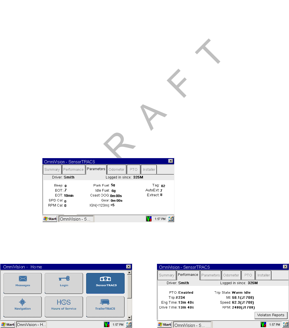
SensorTRACS® System Overview SensorTRACS® Performance Monitoring Verification
13-2 MAY CONTAIN U.S. AND INTERNATIONAL EXPORT CONTROLLED INFORMATION 80-J9968-1 Rev. A
DO NOT COPY
SensorTRACS® System Overview
• The SensorTRACS system is an optional Qualcomm® MCP200 application that records
vehicle and driver performance data.
• The data is then retrieved from the mobile computing platform 200 (MCP200) by the host
computer either manually or automatically at preset intervals.
• The hardware installation on the vehicle consists of:
1. Connecting the MCP200 to the data link or the standard speed and RPM sensors.
2. Sending SensorTRACS parameters from the host computer.
3. Performing system verification.
Performing SensorTRACS® System Verification
Conducting a Road Test
• Vehicle must be set up and appropriate SensorTRACS parameters must be sent to the
vehicle from the host system.
• The PTAG value on the Parameters screen must be a number other than zero.
- Have a passenger accompany you on the road test to review the results on the display
interface unit 200 (MDU200).
1. Start the engine.
2. Touch the SensorTRACS icon and touch the Performance tab to access the
Performance screen.

80-J9968-1 Rev. A MAY CONTAIN U.S. AND INTERNATIONAL EXPORT CONTROLLED INFORMATION 13-3
SensorTRACS® Performance Monitoring Verification SensorTRACS® System Display Screens
DO N OT
COPY
3. Road test the vehicle over a distance of at least one mile.
• Note the beginning mileage on the vehicle’s odometer.
• Have a passenger compare the speed information on the DIU200 to the
speedometer’s readout.
4. Drive the vehicle at various speeds during the road test.
• Compare the speedometer readout with the value displayed on the DIU200 in the
SPD field and verify that they are the same.
5. When you’re finished, check the change in distance (MI field) on the DIU200 to verify
that it corresponds with the distance of the road test, as indicated by the vehicle’s
odometer.
6. If Life-to-Date distance on the Odometer screen does not match the truck’s odometer, it
could be
• the vehicle’s ECM was replaced
• the ECU needs programming
• there is a mismatch between the J1587 and J1939 data links
SensorTRACS® System Display Screens
Accessing the SensorTRACS® Screens
1. Touch the SensorTRACS icon.
• If the SensorTRACS icon is grayed out, the SensorTRACS system is not enabled.
Call your company dispatch to have this application enabled.
2. Touch any of the six tabs to access these individual screens.
• Summary screen
• Performance screen
• Parameters screen
• Odometer screen
• PTO screen
• Installer screen
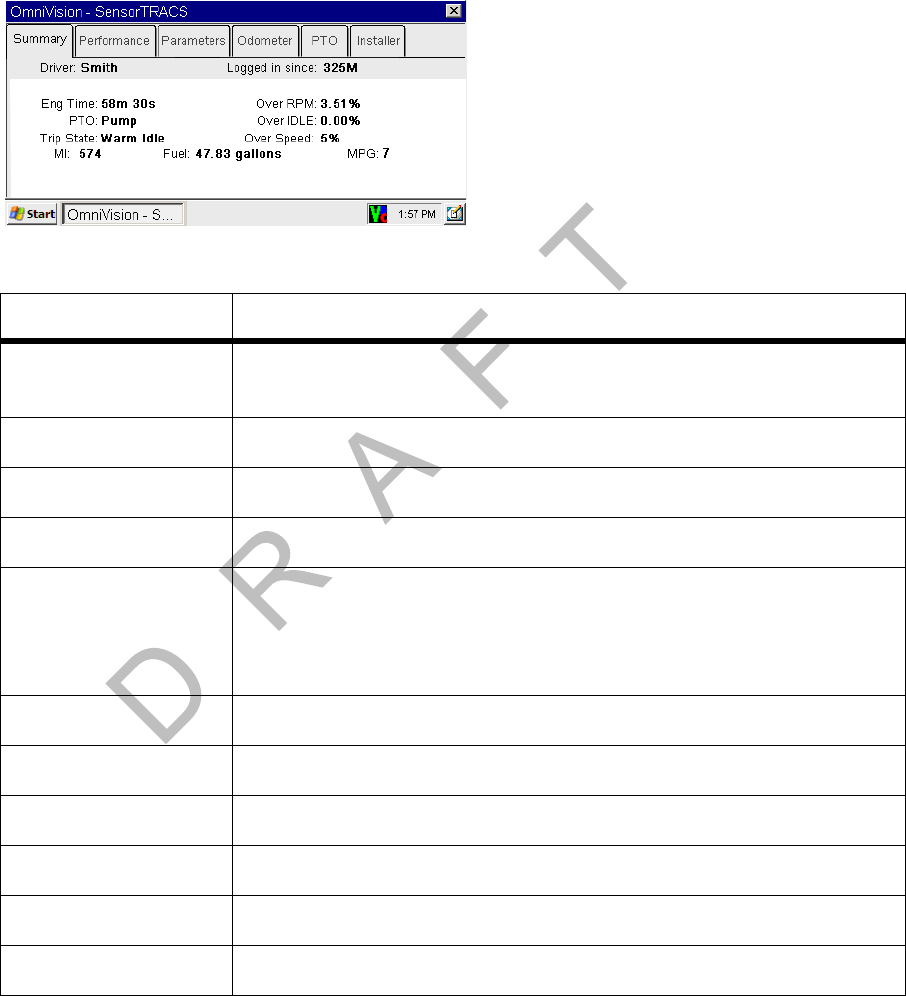
Summary Screen SensorTRACS® Performance Monitoring Verification
13-4 MAY CONTAIN U.S. AND INTERNATIONAL EXPORT CONTROLLED INFORMATION 80-J9968-1 Rev. A
DO NOT COPY
Summary Screen
Data associated with the active driver since the last SensorTRACS system data extract.
Field Description
Driver Active driver name. If no driver is currently logged on as the active
driver, “UNIDENTIFIED” is displayed.
Logged in since Number of minutes current driver has been logged in.
Eng Time Engine time in minutes and seconds.
PTO Indicates if PTO configuration is using Pump or Compressor.
Trip State Current trip state. Possible values are: WARMING IDLE; WARM
IDLE; PRE-INTERTRIP IDLE; PRE-TRIP RUN; PRE-TRIP IDLE;
TRIP RUN; TRIP IDLE; COOL IDLE; POST-INTERTRIP IDLE;
ENGINE STOP; PTO COMP; PTO PUMP; PTO ENGN.
MI Total distance since beginning of trip detected.
Over RPM% Computed over RPM percentage.
Over IDLE Over idle percentage.
Over Speed Computed overspeed percentage.
Fuel Total fuel consumed for trip.
MPG Computed fuel mileage in miles/gallon (or km/gal).
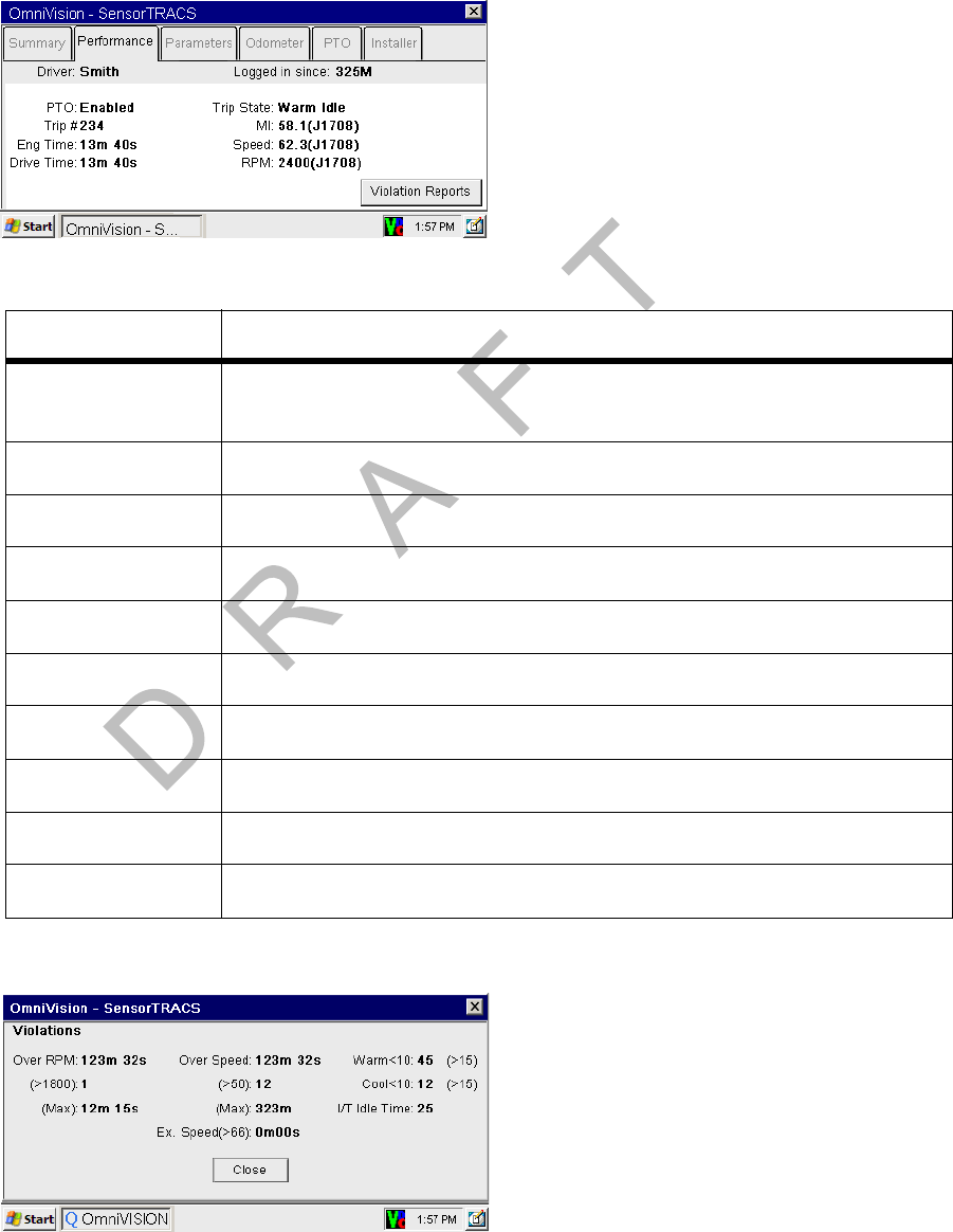
80-J9968-1 Rev. A MAY CONTAIN U.S. AND INTERNATIONAL EXPORT CONTROLLED INFORMATION 13-5
SensorTRACS® Performance Monitoring Verification Performance Screen
DO N OT
COPY
Performance Screen
Data associated with the active driver since the last SensorTRACS system data extract.
Touch the Violations button to view Violation Reports screen.
Field Description
Driver Active driver name. If no driver is currently logged on as the active
driver, “UNIDENTIFIED” is displayed.
Logged in since Number of minutes current driver has been logged in.
PTO Indicates if PTO is Enabled or Disabled
Trip Current trip number.
Eng Time Total elapsed time the engine has been running.
Drive Time Driving (road) time.
Trip State Current trip state.
MI Total miles accumulated.
Speed Current vehicle speed.
RPM Current engine RPM.

Parameters Screen SensorTRACS® Performance Monitoring Verification
13-6 MAY CONTAIN U.S. AND INTERNATIONAL EXPORT CONTROLLED INFORMATION 80-J9968-1 Rev. A
DO NOT COPY
Parameters Screen
Field Description
Driver Active driver name. If no driver is currently logged on as the active
driver, “UNIDENTIFIED” is displayed.
Logged in since Number of minutes the active driver has been logged in.
Beep Unidentified driver beep period in minutes.
BOT Distance vehicle must travel before the MCP200 declares the
Beginning of Trip and starts Trip_Run recording.
EOT End of Trip time threshold in minutes.
SPD Cal Speed calibration parameter.
RPM Cal RPM calibration parameter.
Park Fuel Current value of the amount of fuel used while parked.
Idle Fuel Current value of the idle fuel.
Coast OOG Coasting out-of-gear time (displayed in minutes and seconds).
Gear Current gear ratio based on the current speed and RPM.
IGN Ignition violation time followed by : the ignition violations count.
Tag Parameter version indicator.
AutoExt Dispatch-configured extract frequency (in days).
Extract Unit extract frequency.
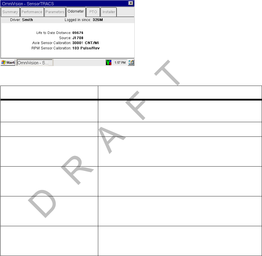
80-J9968-1 Rev. A MAY CONTAIN U.S. AND INTERNATIONAL EXPORT CONTROLLED INFORMATION 13-7
SensorTRACS® Performance Monitoring Verification Odometer Screen
DO N OT
COPY
Odometer Screen
Field Description
Driver Active driver name. If no driver is currently logged on as
the active driver, “UNDENTIFIED” is displayed.
Logged in since Number of minutes current driver has been logged in.
Life to Date Distance Total distance the vehicle has traveled in its lifetime if
data is provided by the ECM, otherwise it is Life To Date
SensorTRACS system miles only.
Source Indicates that the signal source for the vehicle’s
distance is the standard speed sensor (AXLE) or the
J1708/1587 data link (J1708).
Axle Sensor Calibration Speed or distance calibration value. Number should be
the same as the SPD CAL value displayed on the
SensorTRACS Parameters screen.
RPM Sensor Calibration Speed or distance calibration value. Number should be
the same as the RPM CAL value displayed on the
SensorTRACS Parameters screen.
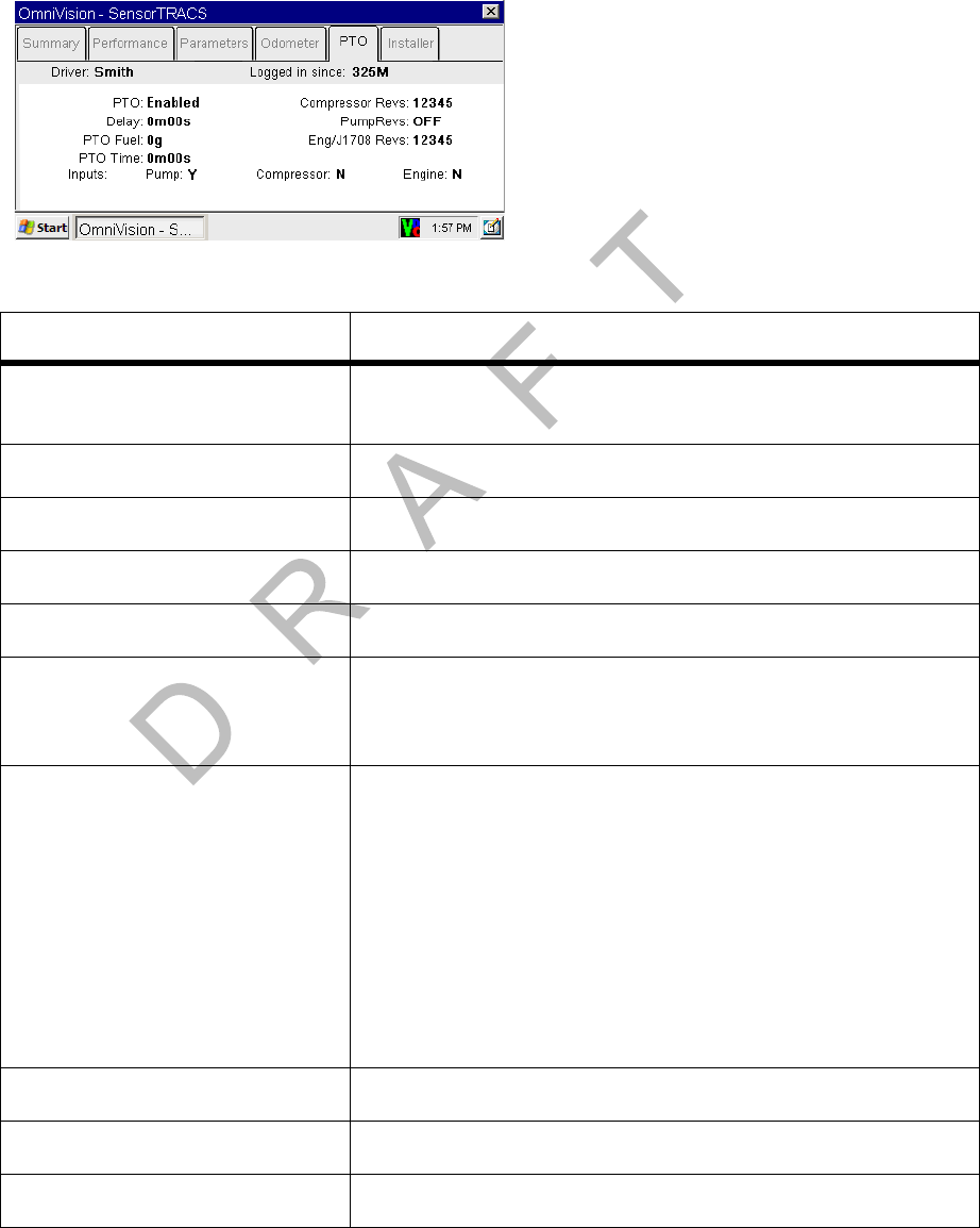
PTO Screen SensorTRACS® Performance Monitoring Verification
13-8 MAY CONTAIN U.S. AND INTERNATIONAL EXPORT CONTROLLED INFORMATION 80-J9968-1 Rev. A
DO NOT COPY
PTO Screen
Field Description
Driver Active driver name. If no driver is logged on as the active
driver, “UNIDENTIFIED” is displayed.
Logged in since Number of minutes current driver has been logged in.
PTO Current state of the PTO (enabled or disabled).
Delay Dispatch-configured time-to-start for PTO time.
PTO Fuel PTO fuel data in gallons.
PTO Time Total time logged as PTO data. (Displayed in minutes and
seconds until the elapsed time exceeds 1 hour; then it is
displayed in hours and minutes.)
Inputs: Pump
Inputs: Compressor
Inputs: Engine
Displays “Y” if the PTOP input is active.
Displays “Y” if the PTOC input is active.
Displays “Y” if the PTOE input is active.
If the PTO is DISABLED or if the VEHICLE IS IN MOTION
(<20 MPH), the INPUTS will always read “N.” If both the
PTOP and PTOC inputs are active, then only the PTOP
input will read “Y.”
Compressor Revs Current value of PTOC revolutions.
Pump Revs Current value of PTOP (pump output shaft) revolutions.
Eng/1708 Revs Current value of PTOE (engine crankshaft) revolutions.
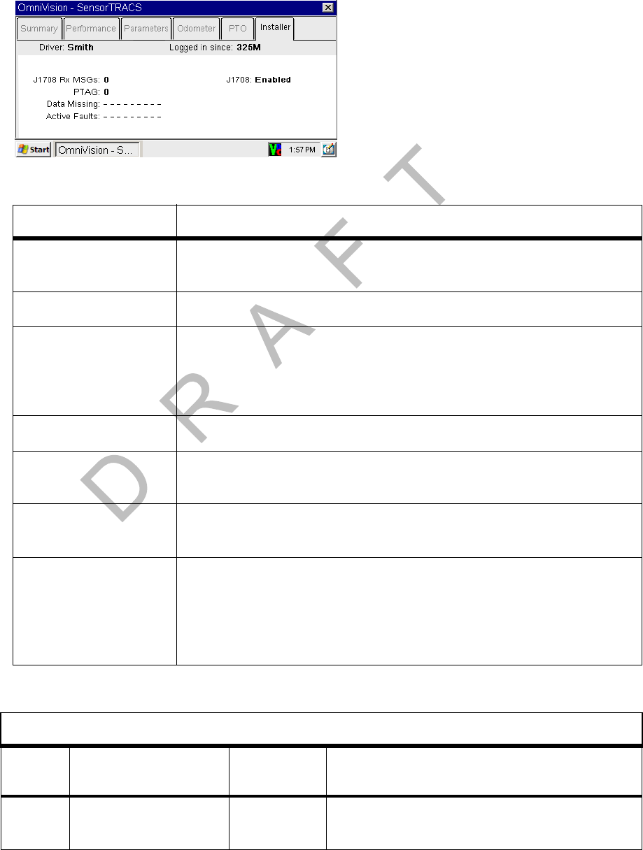
80-J9968-1 Rev. A MAY CONTAIN U.S. AND INTERNATIONAL EXPORT CONTROLLED INFORMATION 13-9
SensorTRACS® Performance Monitoring Verification Installer Screen
DO N OT
COPY
Installer Screen
Field Description
Driver Active driver name. If no driver is logged on as the active driver,
“UNIDENTIFIED” is displayed.
Logged in since Number of minutes current driver has been logged in.
J1708 Rx MSGS Number of J1708 messages received from the engine controller
with the engine running. If this number is not steadily incrementing
several times per second when the engine is running, the J1708/
1587 data link is not correctly connected to the MCP.
PTAG Parameter version tag.
Data Missing Any data that is missing from the J1708/1587 data link. Field
values are described on page 13-9.
Active Faults SensorTRACS faults that are currently active. Field values are
described in the table on page 13-10.
J1708 Enabled
or
J1708 Disabled
The MCP200 is looking at the J1708/1587 data link for the
SensorTRACS data.
The MCP200 is looking at standard and RPM sensors or J1708/
1587 hybrid speed sensor for the SensorTRACS data.
Data Missing Field Value Definitions
Field
Value Meaning
Associated
PID Effect
0 Missing Road Speed
(MPH) 84 SensorTRACS system is not receiving road
speed from the ECM.

Installer Screen SensorTRACS® Performance Monitoring Verification
13-10 MAY CONTAIN U.S. AND INTERNATIONAL EXPORT CONTROLLED INFORMATION 80-J9968-1 Rev. A
DO NOT COPY
1 Missing Engine
Speed (RPM) 190 SensorTRACS system is not receiving
engine speed from the ECM.
2Missing Total
Distance 245 SensorTRACS system is missing distance
from the ECM.
3 Missing Total Engine
Hours 247 Engine hour data will not be available.
4 Missing Total Fuel 250 SensorTRACS system will not record fuel
data.
5 Missing Throttle
Position 91 Coasting will not be a factor in overspeed
threshold.
6 Missing Ambient
Temperature 171 Ambient temperature will not be available.
7 Missing Parking
Brake Status 70 Parked Idle Fuel will not be available.
8 Missing PTO Status 89 PTOE data will not be available.
9 Automatic Traction
Control (ATC) 151 Applies only to CER functionality.
Active Fault Field Value Definitions
Display
Shows
Associated
Fault
Description/
Symptom Possible Cause
0No Power
(MCP) Power detected OFF
for more than the
wake-up time.
Main power was lost, causing the MCP200
to stay asleep longer than its wake-up
interval.
1RPM Zero
(MCP) RPM zero when
speed is non-zero. -RPM sensor or connection problem.
-J1708 selection parameter set wrong.
-In rare cases, no idle can be caused by
faulty axle sensor input (e.g., wires
reversed) causing a positive reading for
speed while the vehicle is stationary.
Data Missing Field Value Definitions
Field
Value Meaning
Associated
PID Effect

80-J9968-1 Rev. A MAY CONTAIN U.S. AND INTERNATIONAL EXPORT CONTROLLED INFORMATION 13-11
SensorTRACS® Performance Monitoring Verification Installer Screen
DO N OT
COPY
2 Bad
Ignition
(MCP)
Ignition OFF and
speed or RPM non-
zero.
Problem with MCP200’s ignition line wiring
or fuse.
3RPM
Sensor
(MCP)
Engine posted PID
(194) and PID (190). RPM sensor or connection problem to the
engine, detected by the engine’s
diagnostics.
4 Speed
Sensor
(MCP)
Engine posted PID
(194) and PID (84). Speed sensor or connection problem to
engine, detected by the engine’s
diagnostics.
9LTD
Mismatch
(MCP)
LTD mismatch with
stored MCP data. -Engine run with main power
disconnected.
-Engine run with data link disconnected.
-Engine run with ignition line
disconnected.
A Bad Speed
(MCP) More than 2 hrs IGN
= ON with Spd = 0,
RPM greater than
1300.
-Speed sensor or connection problem—
MCP200.
-Speed sensor or connection problem—
engine.
-Engine speed sensor parameter not
enabled.
B 0 Spd and
RPM
(MCP)
More than 2 hrs with
IGN = ON with Spd =
0, RPM = 0.
-Disconnect of entire accessory cable.
-J1708 selection parameter set wrong.
-Data link connection problem.
-Driver using ignition position for
accessory operation.
-MCP200 ignition line wired to accessory
position.
D Steady
Speed
(MCP)
Speed signal
constant for more
than 5 minutes.
A pulse generator may have been
connected to either the MCP200 or the
engine.
E Hard
Braking
Event
Speed is suddenly
decreased by more
than 9 MPH/second
(speed must be
above 20 MPH for
this fault to occur.
Driver is braking too quickly (hard braked).
Active Fault Field Value Definitions (Continued)
Display
Shows
Associated
Fault
Description/
Symptom Possible Cause

Special Alert Display Messages SensorTRACS® Performance Monitoring Verification
13-12 MAY CONTAIN U.S. AND INTERNATIONAL EXPORT CONTROLLED INFORMATION 80-J9968-1 Rev. A
DO NOT COPY
Special Alert Display Messages
Certain messages spontaneously display on the display unit when the MCP200 needs to
warn or remind the driver of certain pending conditions.
Warning Messages
Warning messages are accompanied by an audible chirping beep sound from the display unit
speaker.
COASTING OUT OF GEAR. Displays while coasting-out-of-gear time is accumulating.
EXCESSIVE OVERSPEED. Displays while excessive speed time is accumulating.
OVERSPEED. Displays while overspeed time is accumulating.
OVERRPM. Displays while over RPM time is accumulating.
INTERTRIP IDLE IN 60 SECONDS. Displays only once 60 seconds before intertrip idle
accumulation begins.
INTERTRIP IDLE. Displays every 60 seconds for up to five times while intertrip idle time is
accumulating.
Power Take-off (PTO) Overview
• This option provides SensorTRACS vehicle performance monitoring system customers
with the ability to log the time the vehicle engine is used for non-transportation purposes,
such as when it is powering auxiliary devices.
• In order to log PTO time, one of the two PTO wires must be connected to the pump or
compressor input.
• Typically, there are two types of switching methods, those switched to +12 VDC and those
switched to ground.
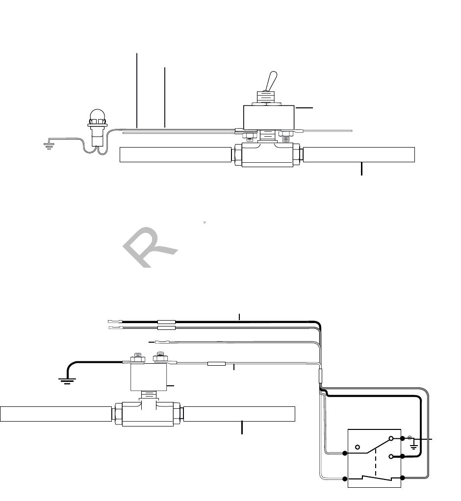
80-J9968-1 Rev. A MAY CONTAIN U.S. AND INTERNATIONAL EXPORT CONTROLLED INFORMATION 13-13
SensorTRACS® Performance Monitoring Verification PTOP (Power Take-off Pump)/PTOC (Power Take-off Compressor)
DO N OT
COPY
PTOP (Power Take-off Pump)/PTOC (Power Take-off Compressor)
1. Engage the PTOP/PTOC.
2. Use your multi-meter to determine which type of circuit you are connecting to.
3. If you only have a switched circuit that is low activated to the ground to detect PTO time,
a relay must be used, as shown in the configuration below.
4. Connect either PTOP or PTOC wires.
5. If the pump activation circuit is +12 VDC (active high) or ground (active low),
connect the white/red PTOP wire from the accessory cable to the PTO side of the
switch.
To PTOP or PTOC Wires
+12 VDC
To PTO indicator light on dash
Ground
Power Take-off Pump (PTOP) or
Power Take-off Compressor (PTOC)
04AAA_217AQMC
P
Indicator
Light
PTO Air line
To air switch on dash to
engage PTO device pump
or compressor
PTO ON/ OFF Switch
PTO Air line
To air switch on dash to
engage PTO device pump
or compressor
Power Take-off Pump (PTOP)
or
Power Take-off Compressor (PTOC)
PTO Ancillary Pressure Switch
WHT
RED
Ground
BRN
BLK
12 Volts
12 Volts
Switched GND
PTOP/PTOC
30
87A
87
86
85
BRN
WHT
BLK
RED
Chassis
GND
PTO Relay
08AAA_062
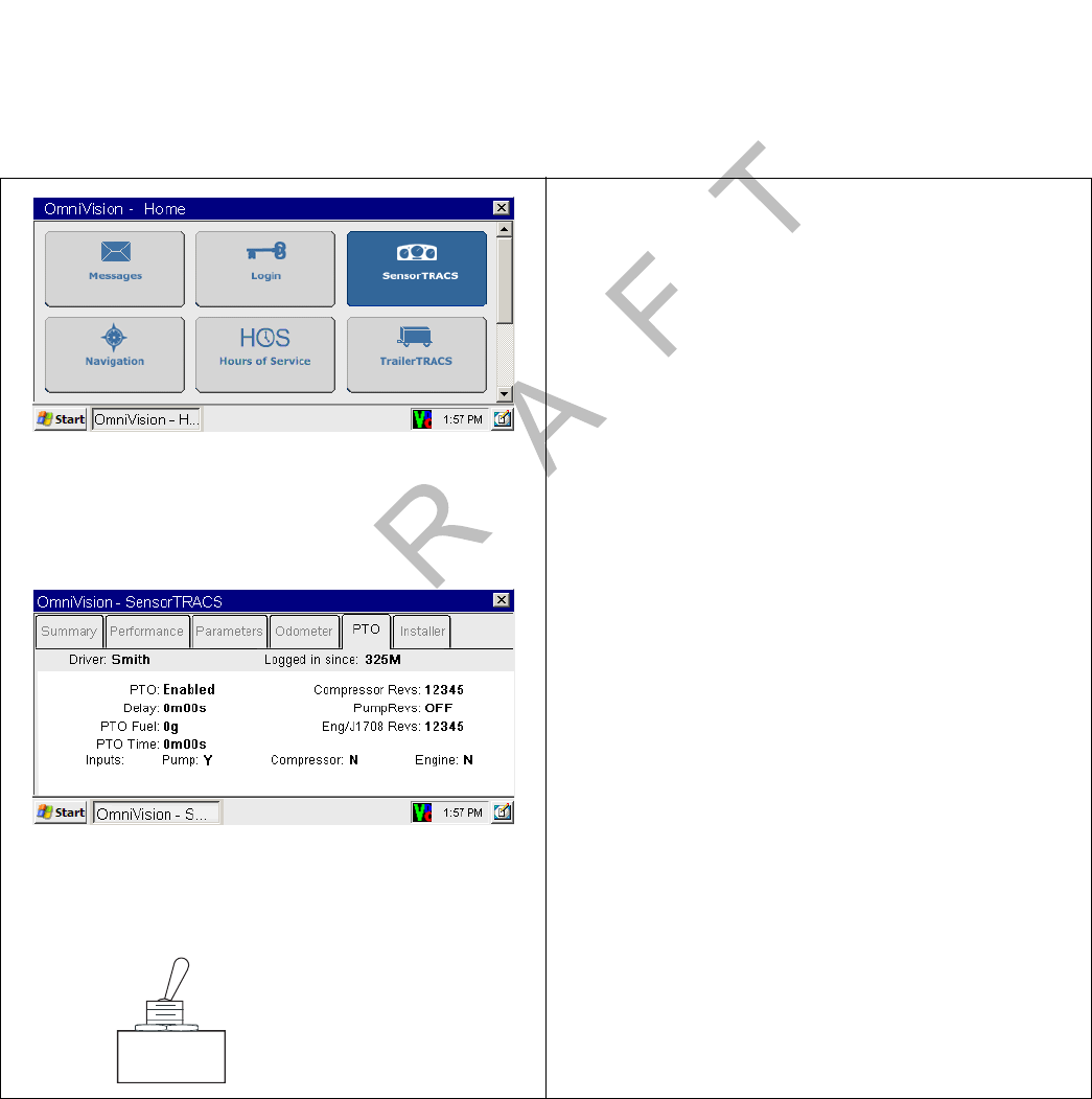
PTO Data Input Verification Procedure SensorTRACS® Performance Monitoring Verification
13-14 MAY CONTAIN U.S. AND INTERNATIONAL EXPORT CONTROLLED INFORMATION 80-J9968-1 Rev. A
DO NOT COPY
If the compressor activation circuit is +12 VDC (active high) or ground (active
low), connect the white/black PTOC wire from the accessory cable to the PTO side of
the switch.
6. Perform the System Verification in Chapter 12 in this guide.
7. Perform the Power Take-off (PTO) Data Input Verification Procedure in PTO Data Input
Verification Procedure on page 13-14.
PTO Data Input Verification Procedure
1. Turn the vehicle ignition ON.
2. Turn the PTO device ON.
3. Navigate to the PTO screen.
• Touch the SensorTRACS icon.
Note
If SensorTRACS is grayed out, SensorTRACS system is
not enabled. Call your company dispatch to have this
application enabled.
• Touch the PTO tab.
4. Verify that PTO is ENABLED and the INPUTS
field displays a Y according to what is active.
• For PTO Information screen field values,
see PTO Screen on page 13-8.
5. To verify that the parameters were sent, check
that the PTO TIME field is incrementing. Is this
field incrementing?
• If yes, PTO verification is complete.
• If no, check the wire connections, see
Power Take-off (PTO) Overview on
page 13-12. Go to step 6.
6. Turn off PTO device. PTO time should now
stop incrementing.

80-J9968-1 Rev. A MAY CONTAIN U.S. AND INTERNATIONAL EXPORT CONTROLLED INFORMATION 14-1
DO NOT COPY
14
Vehicle Maintenance Installation
Topics in this chapter provide a basic overview of the vehicle maintenance service as a
vehicle diagnostics tool that alerts the driver and the fleet of active vehicle diagnostics’
conditions.
Vehicle Maintenance Overview . . . . . . . . . . . . . . . . . . . . . . . . . . . . . . . . . . . . . . . 14-2
Connecting the J1939 Wires . . . . . . . . . . . . . . . . . . . . . . . . . . . . . . . . . . . . . . . . . 14-3
Enabling a Vehicle for Vehicle Maintenance . . . . . . . . . . . . . . . . . . . . . . . . . . . . . 14-3
Vehicle Maintenance System Verification . . . . . . . . . . . . . . . . . . . . . . . . . . . . . . . 14-4
For technical questions, contact Qualcomm Enterprise Services (QESSM) Customer Support.
Customer Support is staffed 24 hours a day, 365 days a year:
In the United States, call 800-541-7490
In Canada, call 800-863-9191

Vehicle Maintenance Overview Vehicle Maintenance Installation
14-2 MAY CONTAIN U.S. AND INTERNATIONAL EXPORT CONTROLLED INFORMATION 80-J9968-1 Rev. A
DO NOT COPY
Vehicle Maintenance Overview
Vehicle maintenance is a vehicle diagnostics tool that alerts the driver and the fleet of active
vehicle diagnostics’ conditions. When a configured engine condition becomes active, the
driver is alerted via the Vehicle Maintenance icon by displaying in orange the number of
active conditions. An e-mail notification is also sent to a pre-subscribed list notifying fleet
personnel of the active condition.
Feature Requirements
• The Qualcomm® mobile computing platform 200 (MCP200) is normally upgraded with
software by sending it over-the-air using satellite transmissions, so that the MCP200
platform should always have the current software version that supports vehicle
maintenance. If you need to perform a manual upgrade using the secure digital (SD) card,
see Appendix D in this guide for detailed information.
• The MCP200 can bus converter cable assembly (CV90-J9389) is required to connect the
J1939 datalink.
• The vehicle maintenance service only supports conditions from the J1939 datalink. The
following conditions are monitored at this time:
Note
For aftermarket installations, the MCP200 J1939 conversion cable is needed.
E-mail notification must be setup by the CSR.
Description Source PGN SPN FMI
Engine power supply voltage (low) 0 65226 627 004
Auxiliary water pump pressure (high) 0 65226 073 003
Auxiliary water pump pressure (low) 0 65226 073 001
Fuel delivery pressure (high) 0 65226 094 003
Engine oil pressure (high) 0 65226 100 003
Engine oil pressure (low) 0 65226 100 001
Engine coolant temperature (high) 0 65226 110 000
Engine coolant temperature (low) 0 65226 110 004
Engine coolant level (high) 0 65226 111 003
Engine coolant level (low) 0 65226 111 001
Engine fuel temperature (high) 0 65226 174 003
Engine oil temperature (high) 0 65226 175 003
Engine oil temperature (above normal) 0 65226 175 000
Brake ABS valve (high) 11 65226 795 003
Brake ABS valve (low) 11 65226 798 004
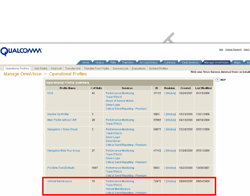
80-J9968-1 Rev. A MAY CONTAIN U.S. AND INTERNATIONAL EXPORT CONTROLLED INFORMATION 14-3
Vehicle Maintenance Installation Connecting the J1939 Wires
DO N OT
COPY
Connecting the J1939 Wires
See Chapter 11 in this guide for detailed information.
Enabling a Vehicle for Vehicle Maintenance
1. Log into iQ at: https://iq.qualcomm.com/qwbs/ngiq/faces/iq/common/Main.jspx
2. Select Manage OmniVision.
• Check to see which Operational Profile is enabled for vehicle maintenance services.
3. Select an Operational Profile to enable a vehicle/unit for Vehicle Maintenance.
4. Select Transfer Unit.
5. Enter the serial number of the unit.
6. Select the Operation Profile for that unit.
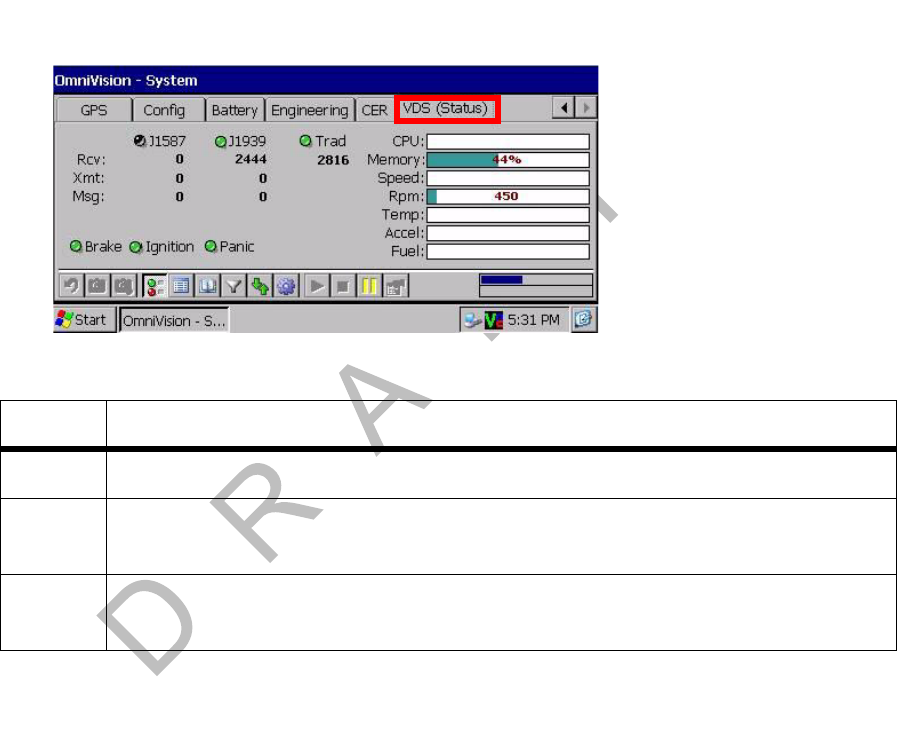
Vehicle Maintenance System Verification Vehicle Maintenance Installation
14-4 MAY CONTAIN U.S. AND INTERNATIONAL EXPORT CONTROLLED INFORMATION 80-J9968-1 Rev. A
DO NOT COPY
Vehicle Maintenance System Verification
Refer to the following DIU200 screens to verify vehicle maintenance:
1. Go to the Vehicle Data Service (VDS) status screen. Press the Home key and scroll
down to the System icon. Touch the System icon and press the VDS tab.
Various screen fields are described below.
With the ignition ON, verify the following on the VDS (Status) screen:
• The J1939 light is green. This confirms that the J1939 is enabled for the unit. The
Rcv value should be constantly increasing.
- If the J1939 light is red, there is an error.
- If the J1939 light is dark, the unit is not enabled for J1939.
• The Brake light is green if the parking brake is engaged.
• The Ignition light is green during this test.
Field Value
RCV These are the packets of data being received on the data bus.
XMT These are the packets of data being received on the data bus as requested
(transmitted) packets.
MSG These are the packets of data being received on the data bus that are of longer
length than the normal data packet size.
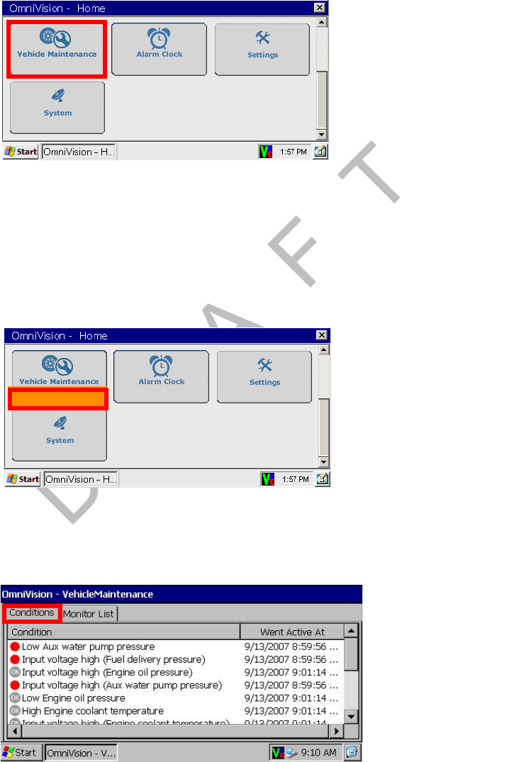
80-J9968-1 Rev. A MAY CONTAIN U.S. AND INTERNATIONAL EXPORT CONTROLLED INFORMATION 14-5
Vehicle Maintenance Installation Vehicle Maintenance System Verification
DO N OT
COPY
2. Press the Home button and scroll down to the Vehicle Maintenance icon.
Note
If the Vehicle Maintenance button is not highlighted blue, the service is not enabled for
the unit and must be turned on via iQ.
3. Simulate an engine condition. The number of conditions you create should appear in
orange on the Vehicle Maintenance icon.
4. Press the Vehicle Maintenance icon and select the Conditions tab to view the current
Active and Inactive Conditions.
• Conditions with red dots are active conditions.
• Conditions with gray dots are inactive conditions.
• The simulated condition should have a red dot.
• Conditions must be active 40 seconds before they are reported on the DIU200.
3 Conditions
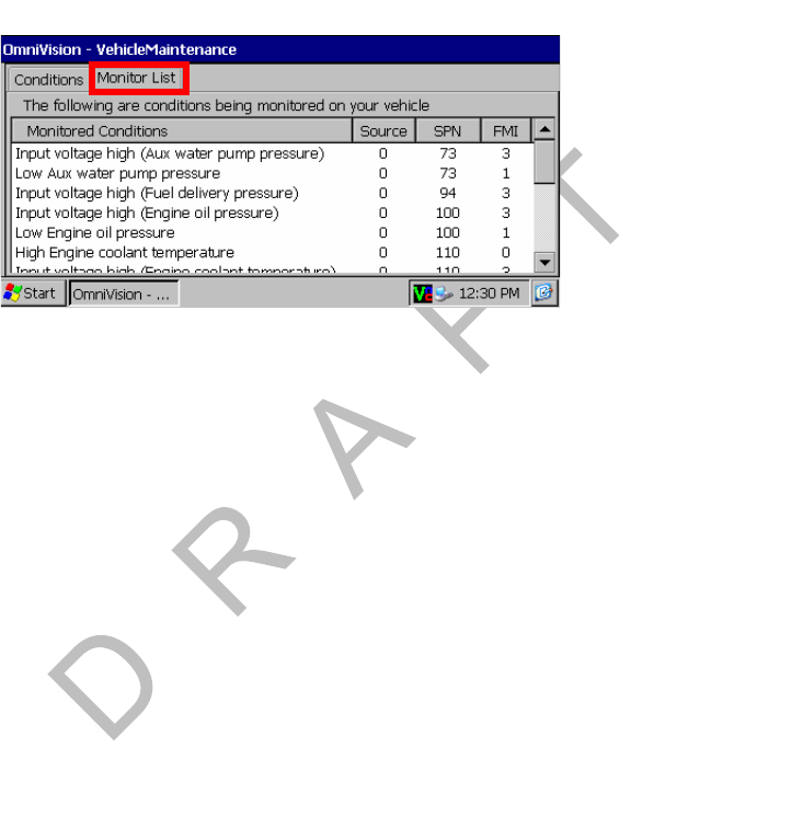
Vehicle Maintenance System Verification Vehicle Maintenance Installation
14-6 MAY CONTAIN U.S. AND INTERNATIONAL EXPORT CONTROLLED INFORMATION 80-J9968-1 Rev. A
DO NOT COPY
• 40 seconds after a condition becomes inactive the dot for that condition turns gray.
• 40 minutes after the condition has been inactive, it is removed from the list.
5. Select the Monitor List tab to view the complete list of monitored Conditions.
6. Verify that e-mail notification goes out upon detection of condition. If you do not receive
e-mail notification, contact QES Customer Support at (800) 541-7490.

80-J9968-1 Rev. A MAY CONTAIN U.S. AND INTERNATIONAL EXPORT CONTROLLED INFORMATION 15-1
DO NOT COPY
15
TrailerTRACS® System Installation
Topics in this chapter provide how to install TrailerTRACS® system hardware on tractors and
trailers and how to verify that the system is working properly.
TrailerTRACS® System Overview . . . . . . . . . . . . . . . . . . . . . . . . . . . . . . . . . . . . . 15-2
TrailerTRACS® System Wiring for the Truck . . . . . . . . . . . . . . . . . . . . . . . . . . . . . 15-2
TrailerTRACS® System Verification. . . . . . . . . . . . . . . . . . . . . . . . . . . . . . . . . . . . 15-3
For technical questions, contact Qualcomm Enterprise Services (QESSM) Customer Support.
Customer Support is staffed 24 hours a day, 365 days a year:
In the United States, call 800-541-7490
In Canada, call 800-863-9191

TrailerTRACS® System Overview TrailerTRACS® System Installation
15-2 MAY CONTAIN U.S. AND INTERNATIONAL EXPORT CONTROLLED INFORMATION 80-J9968-1 Rev. A
DO NOT COPY
TrailerTRACS® System Overview
• Monitors trailer connects and disconnects and passes the information on to dispatch via
the wireless communication network with the date, time, and location.
• Monitors the refrigeration unit of a trailer.
Hardware Requirements
• The MCP200 accessory cable must be installed (see Chapter 5) on the mobile application
server 200 (MAS200).
TrailerTRACS® System Wiring for the Truck
Fuse Kit Installation
Fuse kits are needed for all TrailerTRACS system installations.
1. Locate the blue AUX wire in the 7-way trailer harness. With ignition turned ON,
determine if +12/24 VDC is present on this wire.
• If +12/24 VDC is present, proceed to step 2.
Refrigeration
Unit
TrailerTRACS Transmitter
+12 VDC
Fuse Panel
Trailer Pigtail Connector
TrailerTRACS
Refrigeration
Unit Interface Cable
04 48TQMCP
7-way Receptacle
Trailer Aux Wire
TTracs Input Wire
Display
Unit
MAS
Accessory Cable
TDM
Satellite
Data Modem
Terrestrial
Antenna
To Accessory Cable
TrailerTRACS Input
Blue
(TTRACS)
5 Amp Fuse
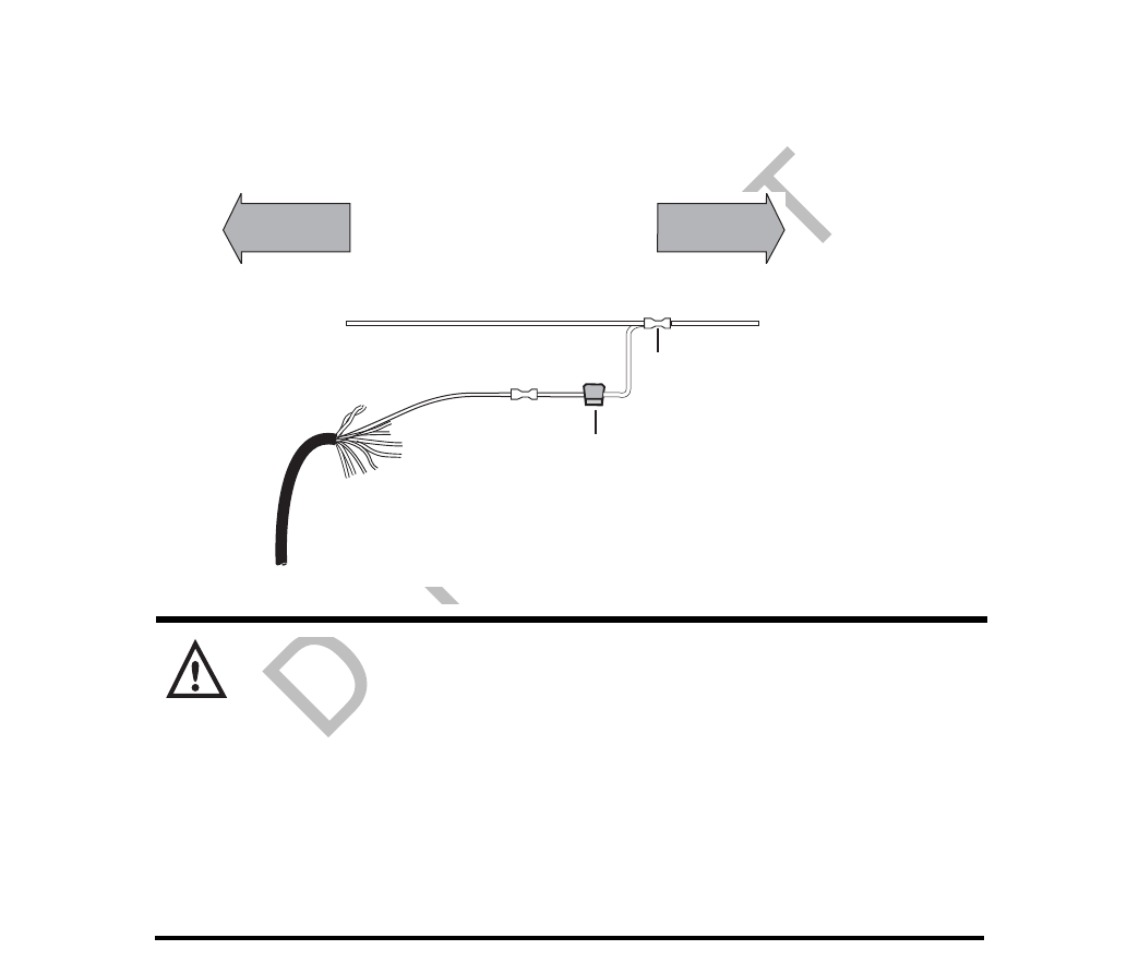
80-J9968-1 Rev. A MAY CONTAIN U.S. AND INTERNATIONAL EXPORT CONTROLLED INFORMATION 15-3
TrailerTRACS® System Installation TrailerTRACS® System Verification
DO N OT
COPY
• If +12/24 VDC is not present, first verify that the main aux fuse is not blown. If no
circuit exists, then connect ignition-switched +12/24 VDC from the fuse panel to the
trailer auxiliary line. The trailer auxiliary wire must be protected by a 30-amp fuse or
a circuit breaker. Proceed to step 2.
2. Locate the trailer auxiliary wire connection point, usually where the trailer auxiliary wire
enters the truck cab.
3. Install the 5-amp fuse on the accessory cable’s blue TTRACS wire.
4. Butt splice the protected end of 5-amp fuse to trailer auxiliary wire connection point.
Caution
Filters: Filtering of the 7-way AUX wire to stop the vehicle’s ABS PLC signal (SAE
2497) from getting into the vehicle electrical system, will also filter the TrailerTRACS
system signal. The TrailerTRACS wire should be connected so it does not go
through the PLC filter.
ABS Interoperability: The TrailerTRACS system product has been tested by
Qualcomm for interoperability with the SAE standard PLC4Trucks ABS signal.
These tests resulted in no adverse impact on the ABS warning function.
Furthermore, Qualcomm is not aware of any interoperability issues in actual
operation on vehicles in the marketplace.
TrailerTRACS® System Verification
Enabling the Option for the TrailerTRACS® System
• If the TrailerTRACS icon is grayed out, TrailerTRACS is not enabled.
• Call your company dispatch to have the correct operational profile selected so this
application is enabled.
Accessory
Cable
Blue (TTRACS)
Trailer Aux wire
to 7-way receptacle
Butt splice
To Tr uck
Fuse Panel
Front of Cab Rear of Cab
04AAA_49
5 Amp Fuse
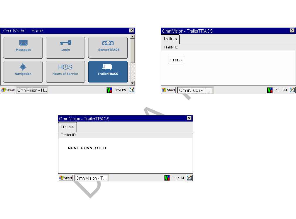
Trailer Connection/Disconnection TrailerTRACS® System Installation
15-4 MAY CONTAIN U.S. AND INTERNATIONAL EXPORT CONTROLLED INFORMATION 80-J9968-1 Rev. A
DO NOT COPY
Trailer Connection/Disconnection
Connection
1. Connect an MCP200-equipped tractor to the trailer, connect the tractor/7-way pigtail.
2. Touch the TrailerTRACS icon.
If a trailer is not currently connected, the status is None Connected.
After the trailer is connected and the TrailerTRACS transmitter sends its ID to the
MCP200, the trailer ID is updated on the display.
Disconnection
1. Remove 7-way pigtail.
2. Leave ignition ON.
3. Wait for disconnect message (approximately five minutes).
A disconnect message is sent when the tractor’s ignition is on and there has been no
signal from the TrailerTRACS transmitter for a preset time period. This usually occurs
within five minutes.
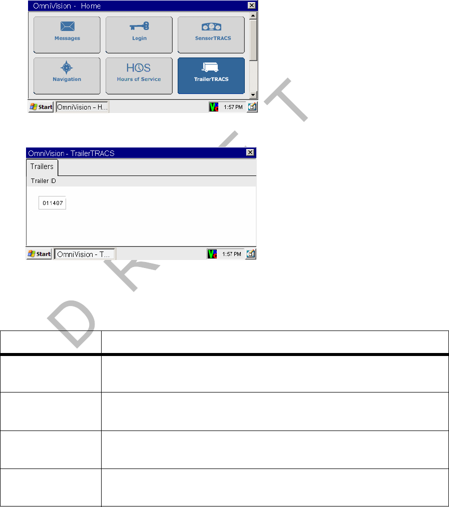
80-J9968-1 Rev. A MAY CONTAIN U.S. AND INTERNATIONAL EXPORT CONTROLLED INFORMATION 15-5
TrailerTRACS® System Installation TrailerTRACS® Diagnostic Screen
DO N OT
COPY
TrailerTRACS® Diagnostic Screen
1. Touch the TrailerTRACS icon.
2. Touch the Trailers tab to display the TRAILER ID screen.
3. When a trailer is connected, the TrailerTRACS Diagnostic screen displays. The
TrailerTRACS transmitter ID shows on the TRAILER ID screen.
A TrailerTRACS ID number displays, as well as other numerical information.
Field Description
First Line
Trailer Diag Number of seconds since the ignition was turned ON.
Second Line
First Number TrailerTRACS ID number.
Second Line
Second Number Number of ID packets from the TrailerTRACS transmitter since the
ignition was turned ON.
Second Line
Third Number Number of seconds since the last ID packet was received from the
TrailerTRACS transmitter by the MCP200.
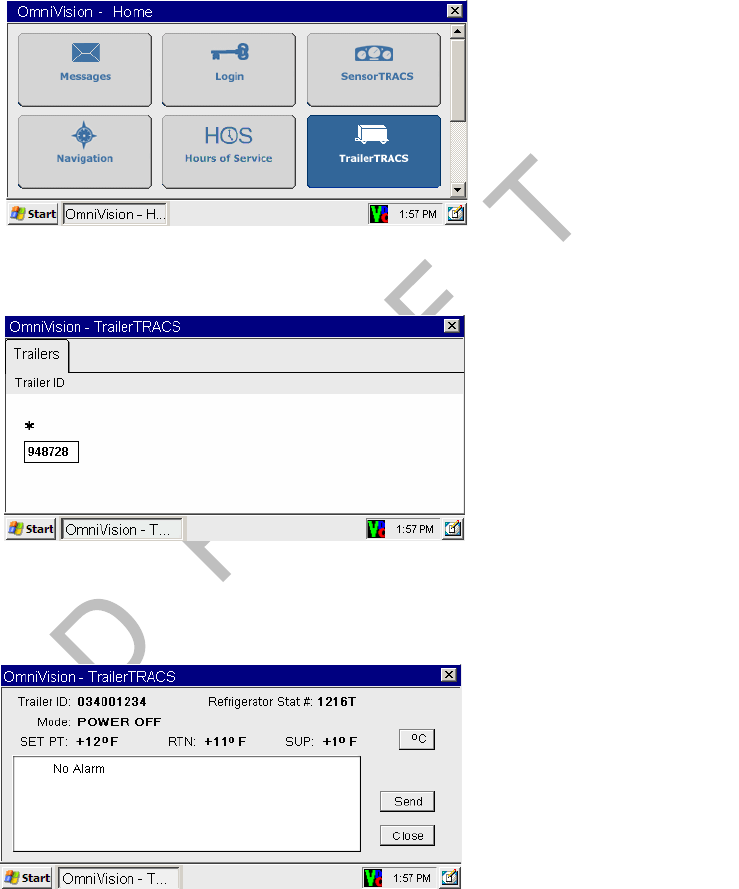
Refrigeration Status Screen TrailerTRACS® System Installation
15-6 MAY CONTAIN U.S. AND INTERNATIONAL EXPORT CONTROLLED INFORMATION 80-J9968-1 Rev. A
DO NOT COPY
Refrigeration Status Screen
1. Touch the TrailerTRACS icon.
2. If a refrigeration unit is detected, a snowflake appears above the transmitter ID box.
Touch the Transmitter box.
3. Refrigeration Status screen appears. To send the information to dispatch, touch the
Send button.

80-J9968-1 Rev. A MAY CONTAIN U.S. AND INTERNATIONAL EXPORT CONTROLLED INFORMATION 15-7
TrailerTRACS® System Installation Refrigeration Status Screen
DO N OT
COPY
Field Description
Trailer ID The trailer’s TrailerTRACS transmitter ID.
Refrigerator Stat # Number of refrigeration status messages sent from the
refrigeration unit to the MCP200. When this number is
incrementing regularly, your data is being sent from the
refrigeration unit.
The number is followed by a code that identifies the refrigeration
unit’s manufacturer:
• T—Thermo King
• C—Carrier
Mode Refrigeration unit’s operating mode.
SET PT Trailer’s set point. Shown in Celsius (C) or Fahrenheit (F).
RTN Temperature of air coming out of the trailer register.
SUP Temperature of air going into the trailer.

Refrigeration Status Screen TrailerTRACS® System Installation
15-8 MAY CONTAIN U.S. AND INTERNATIONAL EXPORT CONTROLLED INFORMATION 80-J9968-1 Rev. A
DO NOT COPY

80-J9968-1 Rev. A MAY CONTAIN U.S. AND INTERNATIONAL EXPORT CONTROLLED INFORMATION 17-1
DO NOT COPY
17
Buzzer Installation
Buzzer Overview
• The message waiting buzzer is an audible alarm triggered by incoming Important, Sleepy
Important, or Emergency messages (the message priority is assigned by the dispatcher).
• It is activated by the message waiting light circuit provided with each Qualcomm®
MCP200. It can be substituted for, or used with, the remote message waiting light
(RMWL).
• Because the buzzer is very loud, an optional toggle switch can be installed to allow the
driver to disable the buzzer.
Topics in this chapter include:
Mounting Location . . . . . . . . . . . . . . . . . . . . . . . . . . . . . . . . . . . . . . . . . . . . . . . . . 17-2
Installation Guidelines . . . . . . . . . . . . . . . . . . . . . . . . . . . . . . . . . . . . . . . . . . . . . . 17-2
Installation Verification . . . . . . . . . . . . . . . . . . . . . . . . . . . . . . . . . . . . . . . . . . . . . . 17-2
For technical questions, contact Qualcomm Enterprise Services (QESSM) Customer Support.
Customer Support is staffed 24 hours a day, 365 days a year:
In the United States, call 800-541-7490
In Canada, call 800-863-9191
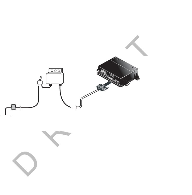
Mounting Location Buzzer Installation
17-2 MAY CONTAIN U.S. AND INTERNATIONAL EXPORT CONTROLLED INFORMATION 80-J9968-1 Rev. A
DO NOT COPY
Mounting Location
• The typical mounting location for the buzzer is behind the dash.
• The toggle switch, when used, can be mounted on the dash.
Installation Guidelines
1. Connect one end of the buzzer power wire to either terminal on the buzzer.
2. To use the optional toggle switch, connect the toggle switch in line with the buzzer
power wire.
3. Connect the green MSG ALERT wire on the MCP200 accessory cable to the other
terminal on the buzzer.
This wire connects the buzzer to ground when activated by the MAS200. It is activated
when an Important or Emergency message is received by the mobile computing
platform (MCP).
Installation Verification
1. Have the dispatcher, or QES Customer Support, 800-541-7490, send an Important or
Sleepy Important message.
2. If the optional toggle switch is installed, turn it OFF and ON and verify that the buzzer
turns OFF and ON when it is activated.
3. With the buzzer activated, read the message sent by the dispatcher and verify that the
buzzer stops sounding.
Buzzer
Green
Toggle
Switch
(Optional)
In-line Fuse
Buzzer Power Wire
+12 VDC
+12VDC
From
Battery
12V
06AAA_84
Accessory Cable
I/0I/0
IUIU
Mobile Application Server
MSG Alert

80-J9968-1 Rev. A MAY CONTAIN U.S. AND INTERNATIONAL EXPORT CONTROLLED INFORMATION 18-1
DO NOT COPY
18
Remote Message Waiting Light (RMWL) Installation
RMWL Overview
• The RMWL can be used when the display unit is located where the driver cannot see the
message waiting light.
• The RMWL illuminates whenever an Important, Sleepy Important, or Emergency message
is received by the Qualcomm® MCP200.
Topics in this chapter include:
Installing the Remote Message Waiting Light . . . . . . . . . . . . . . . . . . . . . . . . . . . . 18-2
Installation Verification . . . . . . . . . . . . . . . . . . . . . . . . . . . . . . . . . . . . . . . . . . . . . . 18-2
For technical questions, contact Qualcomm Enterprise Services (QESSM) Customer Support.
Customer Support is staffed 24 hours a day, 365 days a year:
In the United States, call 800-541-7490
In Canada, call 800-863-9191
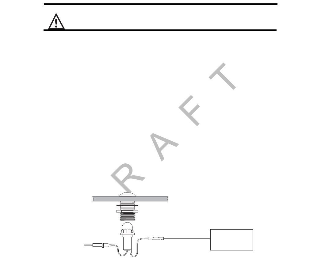
Installing the Remote Message Waiting Light Remote Message Waiting Light (RMWL) Installation
18-2 MAY CONTAIN U.S. AND INTERNATIONAL EXPORT CONTROLLED INFORMATION 80-J9968-1 Rev. A
DO NOT COPY
Installing the Remote Message Waiting Light
Caution
Be sure to clear the area behind the dash before drilling.
1. Select a suitable location for the RMWL. Make sure that there is approximately 2-1/2" of
clearance directly behind the mounting surface where the light will be inserted.
2. Carefully drill a 3/4" diameter hole in the mounting surface.
3. Pull the RMWL bulb assembly straight out of the housing assembly. Remove the nut
and washer from the housing assembly.
4. Insert the RMWL housing assembly into the hole in the mounting surface and re-install
the washer and nut. Tighten the nut until the housing assembly is secured flush against
the vehicle dash and re-install the bulb assembly.
• The power wire can be identified by the in-line fuse holder.
5. Connect the power wire to a +12/+24 VDC unswitched source, such as the BAT+ wire
on the MCP200 power cable.
6. Connect the RMWL’s ground wire to the accessory cable’s green MSG ALERT wire
using a butt splice.
If the RMWL bulb burns out, use a GE53 replacement bulb. The light is protected by a
2-amp in-line fuse.
Installation Verification
1. Have the dispatcher, or QES Customer Support, 800-541-7490, send an Important or
Sleepy Important message.
2. Verify that the light comes ON.
3. Verify that the light goes OFF when the message is read on the display unit.
4. Refer to the Qualcomm® MCP 200 Series and Accessory Diagnostic Guide for
troubleshooting procedures.
Mobile Application
Server
Butt
Splice
+12 VDC
Unswitched
Bulb
Assembly
Housing
Assembly
Washer
Nut
Accessory Cable
MSG ALERT Wire
(green)
Ground
Wire
Mounting
Surface
Fuse
(2 AMP)

80-J9968-1 Rev. A MAY CONTAIN U.S. AND INTERNATIONAL EXPORT CONTROLLED INFORMATION 19-1
DO NOT COPY
19
Wired Panic Button Installation
Wired Panic Button Overview
• The wired panic button meets all Defense Transportation Tracking System (DTTS)
requirements and can be used for vehicles hauling U.S. Department of Defense loads or
hazardous materials.
• It can be configured at the NMC to function as a non-DTTS panic button. When this
configuration is used, the panic button sends an alert to the NMC and an Emergency
message to the dispatcher, but DTTS is not notified.
• For information on installing the wireless panic button, see the Wireless Panic Button
Installation and User Guide (80-J6059-1).
Topics in this chapter include:
Installing the Panic Button . . . . . . . . . . . . . . . . . . . . . . . . . . . . . . . . . . . . . . . . . . . 19-2
Installation Verification . . . . . . . . . . . . . . . . . . . . . . . . . . . . . . . . . . . . . . . . . . . . . . 19-4
For technical questions, contact Qualcomm Enterprise Services (QESSM) Customer Support.
Customer Support is staffed 24 hours a day, 365 days a year:
In the United States, call 800-541-7490
In Canada, call 800-863-9191
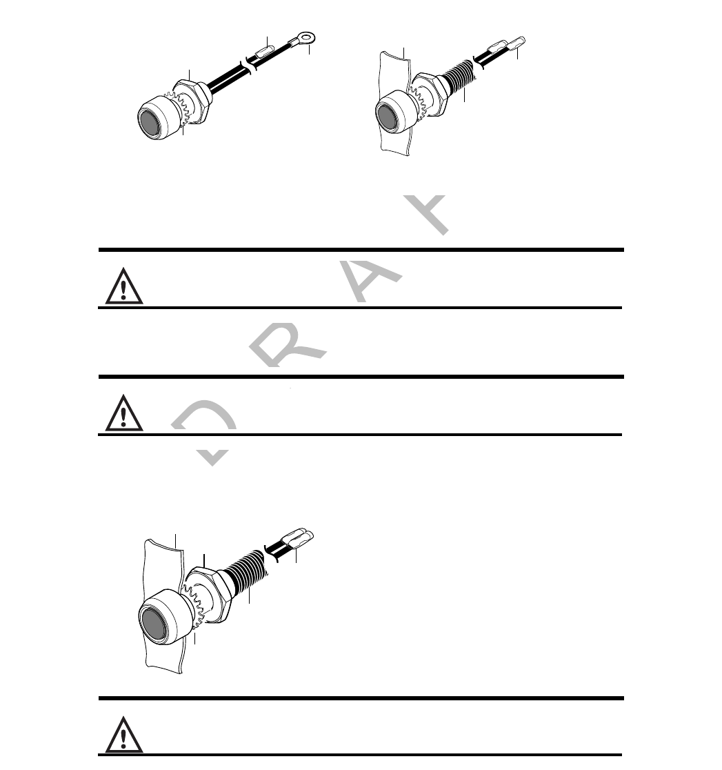
Installing the Panic Button Wired Panic Button Installation
19-2 MAY CONTAIN U.S. AND INTERNATIONAL EXPORT CONTROLLED INFORMATION 80-J9968-1 Rev. A
DO NOT COPY
Installing the Panic Button
1. Install the accessory cable according to the guidelines in Chapter 5.
2. Remove the pre-installed ring terminal and replace with the supplied butt connector.
3. Select a suitable location for the panic button.
Caution
Check behind the dash to ensure that the area is clear of obstructions before drilling.
4. Drill a 5/8" hole in the vehicle dash.
Caution
Always deburr holes before routing the cables.
5. Insert the button assembly into the dash and secure it in place using the lock washer
and nut provided.
WARNING
When routing the cable, avoid any moving parts or sharp edges.
6. Route the cable to where you make the accessory cable connections on the MCP200.
Dash
Panel
Nut
Butt
Connectors
Butt
Connector
Added
Remove
Ring
Terminal
Convoluted
Tubing
Added
Star
Washer
Before Installation After Installation
02AAA_46
Butt
Connectors
02AAA_23
Dash
Panel
Nut
Star
Washer
Convoluted
Tubing
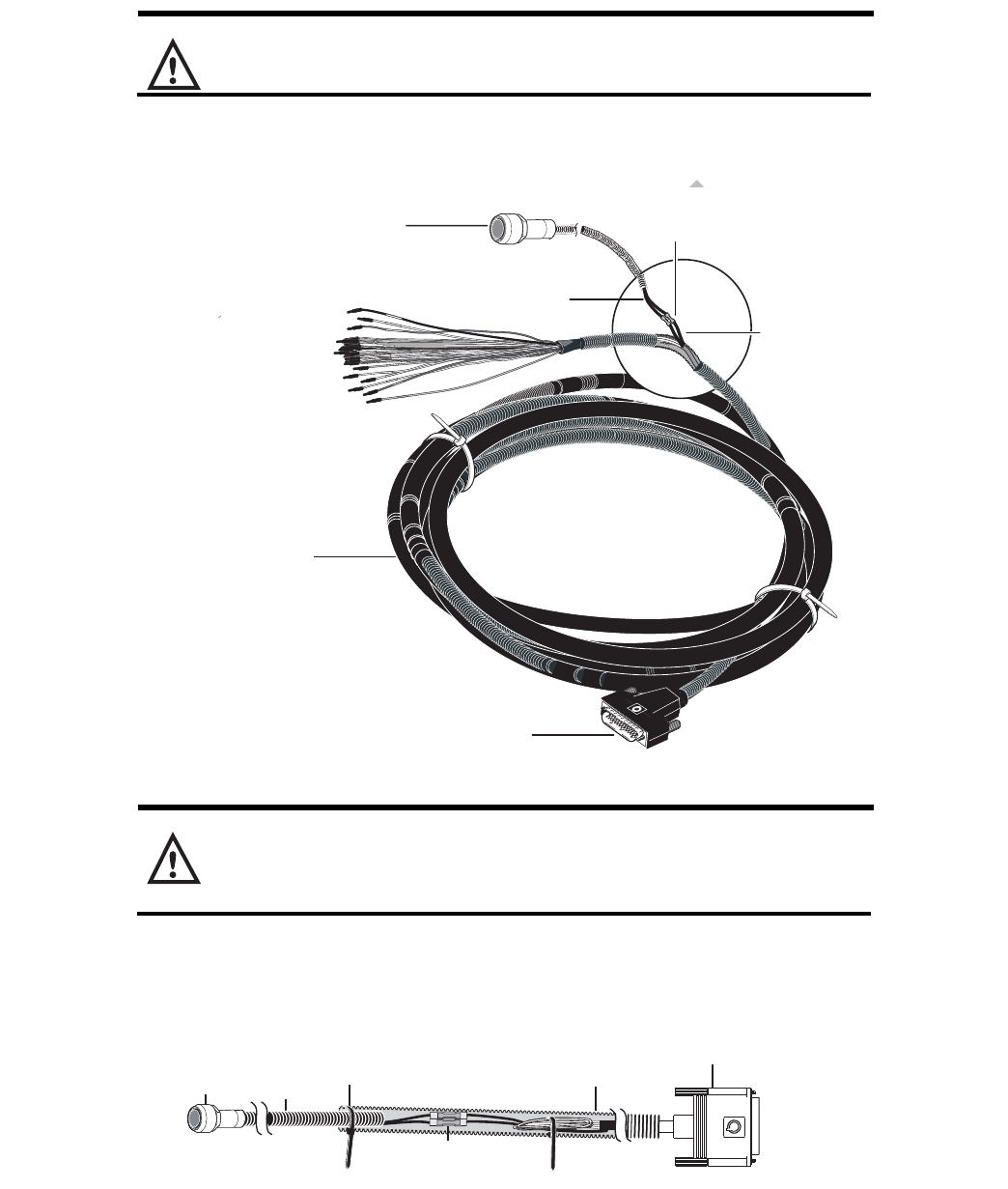
80-J9968-1 Rev. A MAY CONTAIN U.S. AND INTERNATIONAL EXPORT CONTROLLED INFORMATION 19-3
Wired Panic Button Installation Installing the Panic Button
DO N OT
COPY
7. Locate and separate the blue/red PANIC_LOW and blue/black PANIC_HIGH wires from
the other accessory wires on the accessory cable.
Caution
Always use the appropriate crimping tool for insulated terminals.
8. Connect the blue/red PANIC_LOW and blue/black PANIC_HIGH wires to the two wires
of the PANIC button.
Caution
Be sure to cover all wires with convoluted tubing and secure them away from sharp or
moving parts.
9. Once you have completed all connections, cover all wires with convoluted tubing,
secure all loose or unsecured wires with wire ties, and stow away cabling.
44 Pin Connector
05AAA_230B
Convoluted Tubing
Panic Button
Butt
Connectors
Panic Button
Wires (black) PANIC_LOW
(blue/red)
PANIC_HIGH
(blue/black)
Panic
Button
Wire
Tie wrap
large and
small tubing
05AAA_229A
44-Pin
Connector
Butt
Connectors
Panic
Button
Accessory
Cable

Installation Verification Wired Panic Button Installation
19-4 MAY CONTAIN U.S. AND INTERNATIONAL EXPORT CONTROLLED INFORMATION 80-J9968-1 Rev. A
DO NOT COPY
Installation Verification
Automated Panic Button Test System Dial-in Procedure
Before you begin, you need the following:
• The MCP200 serial numbers you are testing.
• Your customer ID.
• Your authorization ID.
If you don’t have this information, contact QES Customer Support at 800-541-7490 before
dialing in to test the procedure.
1. Call QES Customer Support at 800-541-7490.
2. When prompted, press the 0 key for AUTOMATED SERVICES.
3. Press the 7 key for PANIC TESTING.
4. When prompted, enter your customer ID and press the # key.
5. Confirm or re-enter your customer ID.
6. When prompted, enter your authorization ID and press the # key.
7. Confirm or re-enter your authorization ID.
8. If more than one location has been set up for your company, you will hear a list of
locations. Press the number key that corresponds with your current location and press
the # key.
9. When prompted, enter the MCP200 serial number and press the # key.
10. When the serial number is accepted, the number is read back and you receive a
confirmation number.
11. Press the 2 key to enter another MCP200 number or hang up to end the call.
If this process is unsuccessful, hang up and call QES Customer Support at 800-541-
7490 to speak with a representative.
12. You can now press the panic button. You will have an hour to perform the test.
When the test is complete, Qualcomm sends a fax and/or an e-mail to your designated
contact confirming the MCP200s you tested and the number of times you pressed the
panic button for each MCP200 during the test.

80-J9968-1 Rev. A MAY CONTAIN U.S. AND INTERNATIONAL EXPORT CONTROLLED INFORMATION 20-1
DO NOT COPY
20
In-Cab Printer Installation
The in-cab printer is a product of O’Neil Product Development, Inc.
Wiring Configuration. . . . . . . . . . . . . . . . . . . . . . . . . . . . . . . . . . . . . . . . . . . . . . . . 20-2
Installation Guidelines . . . . . . . . . . . . . . . . . . . . . . . . . . . . . . . . . . . . . . . . . . . . . . 20-2
Mounting Bracket . . . . . . . . . . . . . . . . . . . . . . . . . . . . . . . . . . . . . . . . . . . . . . . . . . 20-2
Installing the Printer . . . . . . . . . . . . . . . . . . . . . . . . . . . . . . . . . . . . . . . . . . . . . . . . 20-3
Installation Verification . . . . . . . . . . . . . . . . . . . . . . . . . . . . . . . . . . . . . . . . . . . . . . 20-4
Return Material Authorization (RMA) Process . . . . . . . . . . . . . . . . . . . . . . . . . . . . 20-4
O’Neil Printer Parts List . . . . . . . . . . . . . . . . . . . . . . . . . . . . . . . . . . . . . . . . . . . . . 20-4
For general questions and technical support, contact O’Neil Product Development, Inc.:
In the United States and Canada, call 800-796-6345
Outside these areas, call 949-458-0500
To enable the printer function only, contact Qualcomm Enterprise Services (QESSM) Customer
Support. Customer Support is staffed 24 hours a day, 365 days a year:
In the United States, call 800-541-7490
In Canada, call 800-863-9191

Wiring Configuration In-Cab Printer Installation
20-2 MAY CONTAIN U.S. AND INTERNATIONAL EXPORT CONTROLLED INFORMATION 80-J9968-1 Rev. A
DO NOT COPY
Wiring Configuration
The printer can be connected to the MCP200 in the vehicle using the standard or full function
accessory cable.
Installation Guidelines
Location
Install the printer in the cab of the vehicle in a location that is convenient and safe. This can
be on a vertical or horizontal surface. The printer cannot obscure the driver’s view of the road.
Cables
Keep away from sharp metal edges to avoid damage to cables. Connect the printer to the
vehicle and the MCP200 using the printer power cable and the printer data cable.
Printer Power Cable
The power cable connects to the chassis ground wire and the ignition source.
Printer Data Cable
The data cable connects the printer to the MCP200 primary function accessory cable and
provides the path for data from the MCP200 to the printer.
Mounting Bracket
A swivel mounting bracket is provided for installing the printer to a flat surface. This mounting
bracket works in a variety of locations in a variety of vehicles.
You may also order an optional velcro mount.
08AAA_036B
08AAA_036C
Data Cable

80-J9968-1 Rev. A MAY CONTAIN U.S. AND INTERNATIONAL EXPORT CONTROLLED INFORMATION 20-3
In-Cab Printer Installation Installing the Printer
DO N OT
COPY
Installing the Printer
1. Select the printer location:
• Select a location that is convenient and safe.
• This can be a vertical or horizontal surface.
• Printer cannot obstruct the driver’s view of the road.
2. Install the bracket:
• Use the hardware provided.
• You may also use the optional velcro mount.
3. Install the printer in the bracket.
4. Install the printer power cable:
a. Run the printer power cable from the printer to the MCP200 power cable
connections.
b. Connect the printer GND wire to CHASSIS_GND.
c. Connect the printer IGN wire to ignition source on the vehicle.
5. Install the printer data cable:
a. Run the printer interface cable from the printer to the MCP200 accessory cable
connections.
b. Connect data cable GND wire to violet MCP200 accessory cable COM5_GND
wire.
c. Connect data cable RXD wire to violet/red MCP200 accessory cable
COM5_TX485+ wire.
d. Connect data cable TXD wire to violet/orange MCP200 accessory cable
COM5_RX485- wire.
6. Connect the cables to the printer.
08AAA_036
A

Installation Verification In-Cab Printer Installation
20-4 MAY CONTAIN U.S. AND INTERNATIONAL EXPORT CONTROLLED INFORMATION 80-J9968-1 Rev. A
DO NOT COPY
Installation Verification
Verify that print function is enabled.
1. From the DIU200 Inbox, display a message.
2. Press O or CTRL-P.
• If the Confirmation to print pop-up screen displays, print a message.
• If the Confirmation to print pop-up screen does not display, call QES Customer
Support at 800-541-7490 to have the print function enabled.
Return Material Authorization (RMA) Process
1. Request an RMA from O’Neil Printers.
2. O’Neil arranges shipment of a replacement component to you.
3. Return the failed component to the address specified by O’Neil.
O’Neil Printer Parts List
Order parts directly from O’Neil Product Development, Inc.:
• Call: 800-796-6345 (U.S. and Canada) or 949-458-0500.
• Email: info@oneilprinters.com
• Website: www.oneilprinters.com
Part Part Number
O’Neil Printer Kit contains:
printer, power and data cables, and swivel mounting bracket. 230206-000
O’Neil Printer 200247-103
Power Cable 210292-001
Data Cable 210291-001
Mounting Bracket, swivel 210216-000
Optional Velcro Mount 220264-000

80-J9968-1 Rev. A MAY CONTAIN U.S. AND INTERNATIONAL EXPORT CONTROLLED INFORMATION 21-1
DO NOT COPY
21
In-Cab Scanner Installation
The in-cab scanner is a product of BCS Solutions.
Installation Guidelines . . . . . . . . . . . . . . . . . . . . . . . . . . . . . . . . . . . . . . . . . . . . . . 21-2
Mounting the Scanner . . . . . . . . . . . . . . . . . . . . . . . . . . . . . . . . . . . . . . . . . . . . . . 21-2
Installing the Scanner. . . . . . . . . . . . . . . . . . . . . . . . . . . . . . . . . . . . . . . . . . . . . . . 21-3
Calibrating the Scanner . . . . . . . . . . . . . . . . . . . . . . . . . . . . . . . . . . . . . . . . . . . . . 21-3
Sending a Scan . . . . . . . . . . . . . . . . . . . . . . . . . . . . . . . . . . . . . . . . . . . . . . . . . . . 21-4
Cleaning the Scanner. . . . . . . . . . . . . . . . . . . . . . . . . . . . . . . . . . . . . . . . . . . . . . . 21-5
Return Material Authorization (RMA) Process . . . . . . . . . . . . . . . . . . . . . . . . . . . . 21-5
BCS Solutions Scanner Parts List . . . . . . . . . . . . . . . . . . . . . . . . . . . . . . . . . . . . . 21-6
For technical support, contact BCS Solutions:
In the United States and Canada, call 800-555-5555
For initial support only, contact Qualcomm Enterprise Services (QESSM) Customer Support.
Customer Support is staffed 24 hours a day, 365 days a year:
In the United States, call 800-541-7490
In Canada, call 800-863-9191
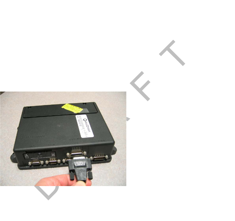
Installation Guidelines In-Cab Scanner Installation
21-2 MAY CONTAIN U.S. AND INTERNATIONAL EXPORT CONTROLLED INFORMATION 80-J9968-1 Rev. A
DO NOT COPY
Installation Guidelines
• Check with your local CSR for the minimum software versions needed to support
navigation.
Location
Install the scanner in the cab of the vehicle in a location that is convenient and safe. This can
be on a vertical or horizontal surface. The scanner cannot obscure the driver’s view of the
road.
Scanner Cable
Keep away from sharp metal edges to avoid damage to cable. Connect the scanner to the
MCP200 using the 15-pin DSUB connector.
Mounting the Scanner
The scanner can be mounted in one of two ways.
Scanner Mounting Option
1. Cut the dual-lock tape into four 2.5" sections.
2. Clean the scanner bottom with an alcohol pad, remove protective film and apply two
dual-lock pieces to the bottom ends of the scanner.
3. Clean the vehicle’s mounting surface with an alcohol pad.
4. Remove protective film and apply two dual-lock pieces to the desired mounting surface.
Holster Mounting Option
1. Select holster location.
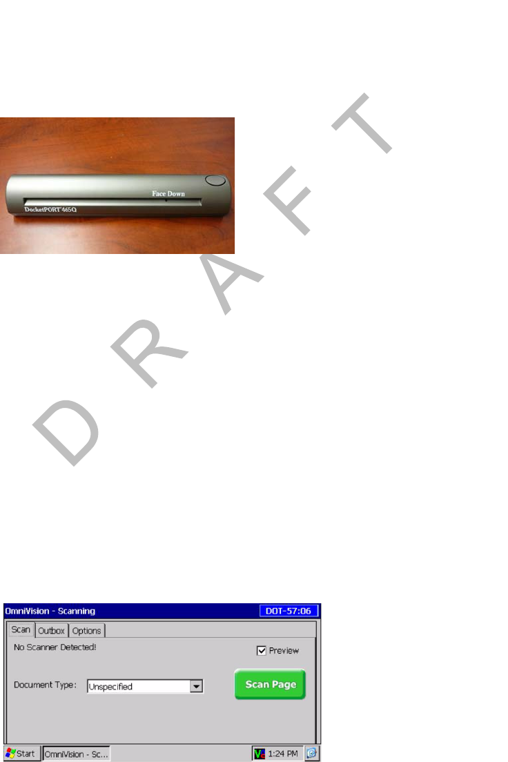
80-J9968-1 Rev. A MAY CONTAIN U.S. AND INTERNATIONAL EXPORT CONTROLLED INFORMATION 21-3
In-Cab Scanner Installation Installing the Scanner
DO N OT
COPY
2. Clean the location with an alcohol pad and let dry.
3. Carefully remove film from four VHB adhesive locations on holster.
4. Position holster onto desired location and firmly press each corner to ensure contact
with the surface.
5. Self-drilling screws can be installed for more support.
Installing the Scanner
1. Remove the metal cover from the MAS200 USB/SER connector.
2. Connect the 15-pin DSUB cable end of the scanner to the MAS200. Determine where
to locate the scanner. If installing the holster, use four VHB adhesive pads (self-tapping
screws optional). If mounting the scanner only, use dual-lock tape.
3. Go to Scanner Mounting Option on page 21-2 or Holster Mounting Option on page 21-2
for mounting options.
4. Route the scanner cable where it will not be damaged and is out of harm’s way and will
not obstruct the driver or hinder truck performance.
Note
It may be necessary to route cable under the wells and truck interior molding.
Calibrating the Scanner
1. From the Scanning Home screen, touch the Options tab.
2. Insert the black and white calibration page or plain white paper into the slot.
Sending a Scan In-Cab Scanner Installation
21-4 MAY CONTAIN U.S. AND INTERNATIONAL EXPORT CONTROLLED INFORMATION 80-J9968-1 Rev. A
DO NOT COPY
3. Touch the Calibrate button. Wait a few minutes for the calibration to complete.
4. Touch the Scan tab to return to the scanning home screen.
Sending a Scan
1. On the Home screen, touch the Scanner button.
2. Insert the paper, face down.
• It will go in about 1/2".
• If it’s not 8-1/2" wide, line it up with the right edge.
Note
The small tooth in the slot must be covered.
3. Touch the Scan Page button.
Note
If the preview box is checked, a preview page appears. Touch the Accept or Reject
button.
4. After the page goes through, insert another page and touch the Add Page button, or if
you are finished, touch the Done button.

80-J9968-1 Rev. A MAY CONTAIN U.S. AND INTERNATIONAL EXPORT CONTROLLED INFORMATION 21-5
In-Cab Scanner Installation Cleaning the Scanner
DO N OT
COPY
5. Identify what you’re sending and touch the Send button.
6. When asked to confirm, touch the Yes button.
Cleaning the Scanner
1. Touch the Options tab.
2. Insert the cleaning paper.
3. Touch the Clean button. Wait a few minutes while the scanner draws through the
cleaning paper and cleans the scanner.
Return Material Authorization (RMA) Process
1. Request an RMA from BCS Solutions.
2. BCS Solutions arranges shipment of a replacement component to you.
3. Return the failed component to the address specified by BCS Solutions.

BCS Solutions Scanner Parts List In-Cab Scanner Installation
21-6 MAY CONTAIN U.S. AND INTERNATIONAL EXPORT CONTROLLED INFORMATION 80-J9968-1 Rev. A
DO NOT COPY
BCS Solutions Scanner Parts List
Order parts directly from BCS Solutions:
• Call: 800-555-5555.
• Website: www.bcssolutions.com
Part Part Number
BCS Scanner Kit contains:
scanner, scanner cable, and holster 65-J9630-1
BCS Scanner Kit contains:
scanner and scanner cable 65-J9630-2
BSC Scanner 825-53392-0000
Scanner Cable 45-J9652-16
Optional Holster 65-J9631-1

80-J9968-1 Rev. A MAY CONTAIN U.S. AND INTERNATIONAL EXPORT CONTROLLED INFORMATION A-1
DO NOT COPY
A
Wiring Diagrams and Charts
Topics in this appendix provide wiring diagrams and pin description charts for the
Qualcomm® mobile computing platform 200 (MCP200) and accessories.
Qualcomm® MCP200 Electrical Diagram . . . . . . . . . . . . . . . . . . . . . . . . . . . . . . . . A-2
Qualcomm® MCP200 Wiring Diagram . . . . . . . . . . . . . . . . . . . . . . . . . . . . . . . . . . A-3
Power Cable Connector Pin Callouts. . . . . . . . . . . . . . . . . . . . . . . . . . . . . . . . . . . . A-4
Wireless Interface Box (WIB) Cable Connector Pin Callouts. . . . . . . . . . . . . . . . . . A-5
Optional Satellite Data Modem (SDM) Cable 9-Pin Connector Callouts . . . . . . . . . A-6
Primary Accessory Cable Connector Pin Callouts. . . . . . . . . . . . . . . . . . . . . . . . . . A-7
Secondary Accessory Cable Connector Pin Callouts . . . . . . . . . . . . . . . . . . . . . . . A-8
Display Interface Unit 200 (DIU200) Cable Connector Pin Callouts . . . . . . . . . . . . A-9
Six-pin Data Link Connector Pin Callouts . . . . . . . . . . . . . . . . . . . . . . . . . . . . . . . A-10
Nine-pin Data Link Connector Pin Callouts . . . . . . . . . . . . . . . . . . . . . . . . . . . . . . A-11
Radio Connector Pin Callouts . . . . . . . . . . . . . . . . . . . . . . . . . . . . . . . . . . . . . . . . A-12
CAN Conductor Cable Pin Callouts . . . . . . . . . . . . . . . . . . . . . . . . . . . . . . . . . . . . A-13
For technical questions, contact Qualcomm Enterprise Services (QESSM) Customer Support.
Customer Support is staffed 24 hours a day, 365 days a year:
In the United States, call 800-541-7490
In Canada, call 800-863-9191
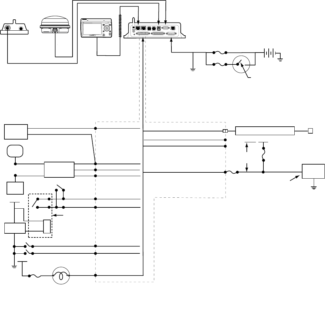
Qualcomm® MCP200 Electrical Diagram Wiring Diagrams and Charts
A-2 MAY CONTAIN U.S. AND INTERNATIONAL EXPORT CONTROLLED INFORMATION 80-J9968-1 Rev. A
DO NOT COPY
Qualcomm® MCP200 Electrical Diagram
SDM
Antenna
SDM
Cable
WIB
Cable Chassis
Gnd
DIU
Cable
Message
Waiting Light
+9 VDC to +32 VDC
Vehicle Battery
10 AMP
3 AMP
30 AMP
Optional
RCD
RCD
Speaker
Switch
Truck
Spkr
Truck
Stereo
Speaker +
Speaker -
Panic
Switch
Relay
Harness
PWR
PWR
Wireless
Panic
Panic
Signal
Pump
Compressor
PTOP
PTOC
2 AMP
PWR
MSG Alert
Can Converter Cable
7- Way AUX
5 AMP
TTRACS
J1708+
J1708-
TTRACS
XMTR
Mounted on Trailer
Panic High
Panic Low
10'
min.
Primary Accessory Cable
Power Cable
Ignition Switch
MAS200
Optional
!
IO 2 IO 1 PWR
DIU200
WIB200
Antenna
09AAA_022
Accessory1_ Gnd
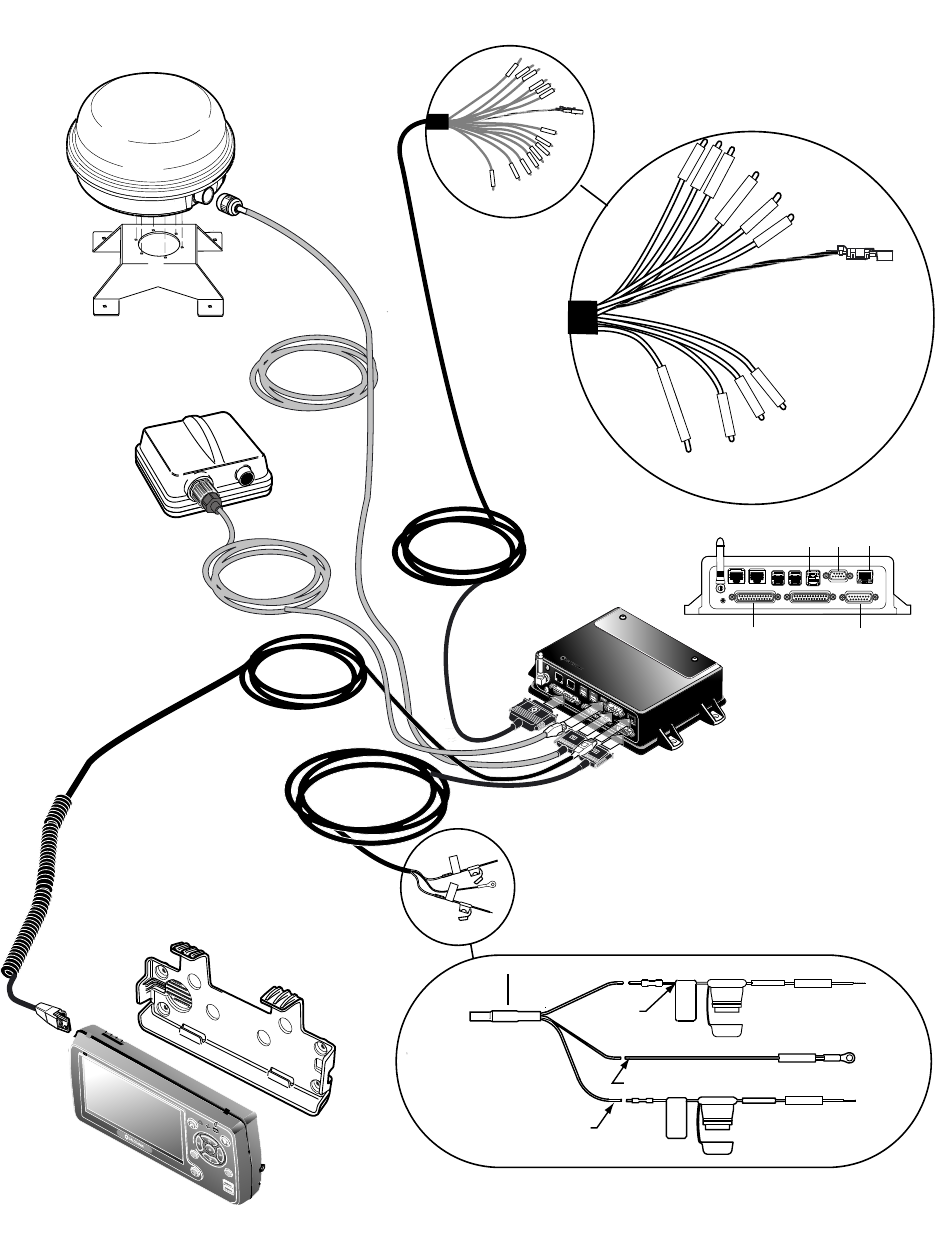
80-J9968-1 Rev. A MAY CONTAIN U.S. AND INTERNATIONAL EXPORT CONTROLLED INFORMATION A-3
Wiring Diagrams and Charts Qualcomm® MCP200 Wiring Diagram
DO N OT
COPY
Qualcomm® MCP200 Wiring Diagram
Vehicle Dash/
Electrical Center
BLU /GRN
BLU/BLK
GRN
VIO/RED
VIO
BRN
BLU
BLU/RED
RCD
Panic_Low
MSG_ Alert
MCP Wiring Diagram
I/0I/0
Mobile Application Server
Power Cable
DIU Cable
Panic_High
PTOP
PTOC
J1708+
J1708-
TTRACS
RED
VIO/ORN
I/O Cable
Power Cable
15-AMP
BAT+
BLACK
BAT RTN
WHITE
YELLOW
3-AMP
IGNITION
3-AMP
CAN1 Connector
Optional
Satellite Data Modem
SDM Cable
Accessory1_Gnd
WIB Cable
Wireless Interface Box
(WIB200)
Antenna
(MAS200)
(SDM)
and Mount
09AAA_023
(DIU200)
and Holster
Display Interface Unit
DIU
WIB
SDM
PWR
IO 1
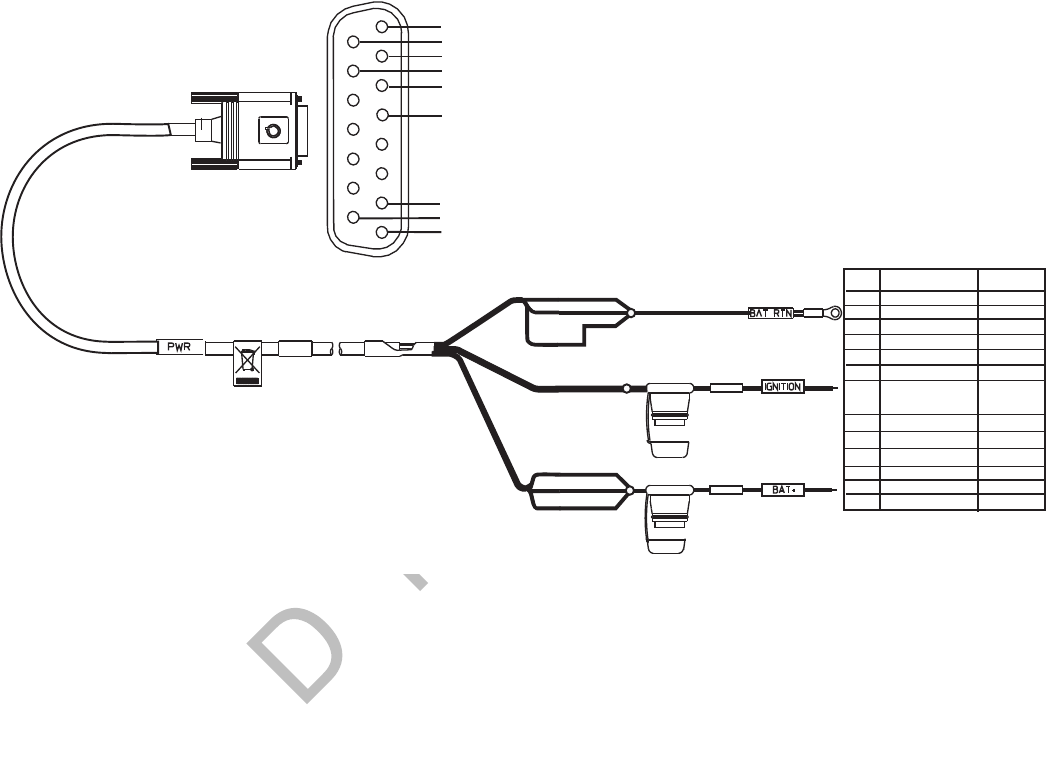
Power Cable Connector Pin Callouts Wiring Diagrams and Charts
A-4 MAY CONTAIN U.S. AND INTERNATIONAL EXPORT CONTROLLED INFORMATION 80-J9968-1 Rev. A
DO NOT COPY
Power Cable Connector Pin Callouts
1 (BAT+) 12 VDC
2 (BAT+) 12 VDC
8 (BAT RTN)
5 (IGNITION)
Switched 12VDC
7 (BAT RTN)
6 (ID)
SIGNAL COLOR
PIN
15 (BAT RTN)
14 (BAT RTN)
9 (BAT+) 12 VDC
YELLOW
YELLOW
YELLOW
BLACK
BLACK
BLACK
BLACK
WHITE
8
15
7
14
6
5
2
9
1
06A
3AMP
Fuse
10AMP
Fuse
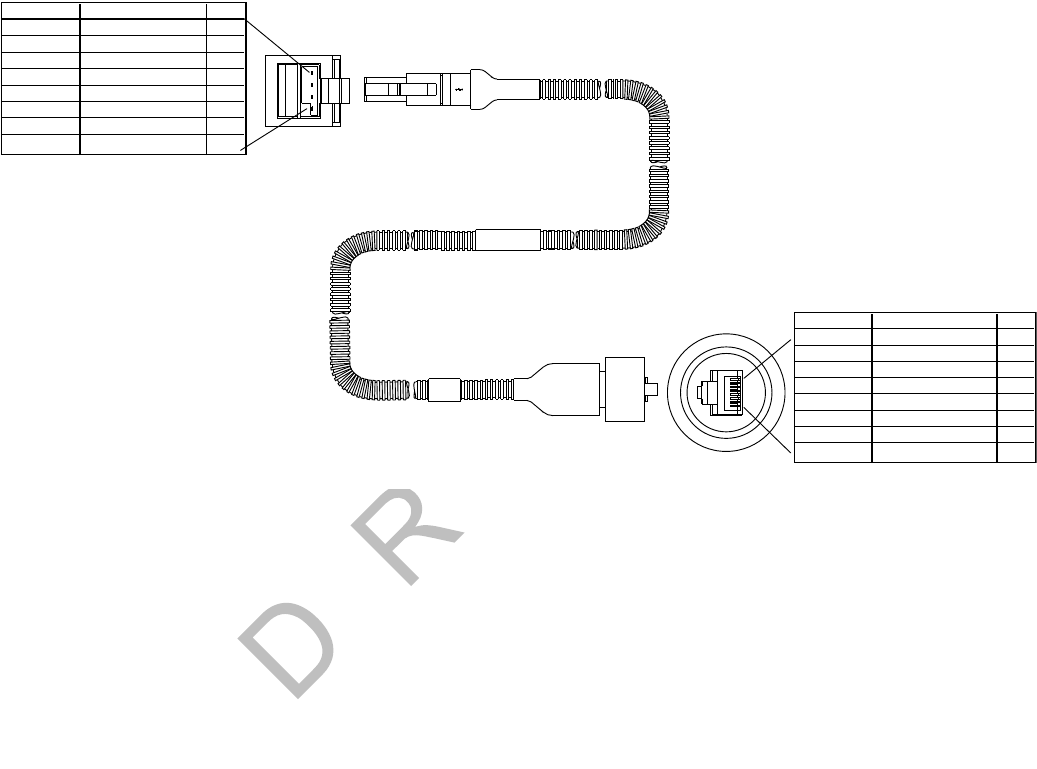
80-J9968-1 Rev. A MAY CONTAIN U.S. AND INTERNATIONAL EXPORT CONTROLLED INFORMATION A-5
Wiring Diagrams and Charts Wireless Interface Box (WIB) Cable Connector Pin Callouts
DO N OT
COPY
Wireless Interface Box (WIB) Cable Connector Pin Callouts
09AAA_016
PIN
SIGNAL
1
1
2
3
4
5
6
7
8
WIB _TEMPER_1
WIB _TEMPER_2
WIB _Gnd
WIB _Gnd
WIB _DATA_P
WIB _DATA_M
WIB_9 V
WIB_9 V
COLOR
Green
Yellow
Blue
Violet
Orange
Gray
Black
Red
7
2
3
4
6
WIB _TEMPER_1
WIB _TEMPER_2
WIB _Gnd
WIB _Gnd
WIB _DATA_P
WIB _DATA_M
WIB_9 V
Green
Yellow
Blue
Violet
Orange
Gray
Black
Red
PIN
SIGNAL
COLOR
8
5
USB_VCC
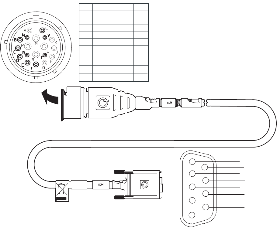
Optional Satellite Data Modem (SDM) Cable 9-Pin Connector Callouts Wiring Diagrams and Charts
A-6 MAY CONTAIN U.S. AND INTERNATIONAL EXPORT CONTROLLED INFORMATION 80-J9968-1 Rev. A
DO NOT COPY
Optional Satellite Data Modem (SDM) Cable 9-Pin Connector Callouts
06AAA_130
ERTN 5
FRTN 6
BTAMPER 7
P1
SIGNAL P2
VRX- 3
N RX+ 4
R TX+ 1
TTX- 2
LDrain
PIN
7
4
C
D
PWR 9.9-11.5VDC
PWR 9.9-11.5VDC
8
9
1
6
2
3
8
9
5
P1
P2
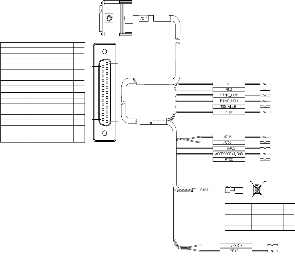
80-J9968-1 Rev. A MAY CONTAIN U.S. AND INTERNATIONAL EXPORT CONTROLLED INFORMATION A-7
Wiring Diagrams and Charts Primary Accessory Cable Connector Pin Callouts
DO N OT
COPY
Primary Accessory Cable Connector Pin Callouts
09AAA_014
25
14
13
1
WHT/BLU 20WHT/BLU 20
BLU/WHT 20BLU/WHT 20
GRN 22GRN 22
GRN 22
RED 22RED 22
RED 22
BRN 22BRN 22
BRN 22
BLU/BLK 22BLU/BLK 22
BLU/BLK 22
BLU/RED 22BLU/RED 22
BLU/RED 22
BLU 22BLU 22
BLU 22
VIO/ORN 22VIO/ORN 22
VIO/ORN 22
VIO/RED 22VIO/RED 22
VIO/RED 22
BLU/GRN 22BLU/GRN 22
BLU/GRN 22
VIO 22VIO 22
VIO 22
BLU/YEL 22BLU/YEL 22
BLU/YEL 22
BLU/VIO 22BLU/VIO 22
BLU/VIO 22
BLU/GRA 22BLU/GRA 22
BLU/GRA 22
(CAN_D(PWR))(CAN_D(PWR))
(CAN_A(RX))(CAN_A(RX))
PIN 3
PIN 1
PIN 4
PIN 2
WHT/BRN 22WHT/BRN 22
BRN/WHT 22BRN/WHT 22
WHT/BRN 22WHT/BRN 22
BRN/WHT 22BRN/WHT 22
GRN 22GRN 22
RED 22RED 22
BRN 22BRN 22
BLU/BLK 22BLU/BLK 22
BLU/RED 22BLU/RED 22
BLU 22BLU 22
VIO/ORN 22VIO/ORN 22
VIO/RED 22VIO/RED 22
BLU/GRN 22BLU/GRN 22
WHT/BLU 20WHT/BLU 20
BLU/WHT 20BLU/WHT 20
VIO 22VIO 22
BLU/YEL 22BLU/YEL 22
BLU/VIO 22BLU/VIO 22
BLU/GRA 22BLU/GRA 22
(CAN_B(TX))(CAN_B(TX))
(CAN_C(GND))(CAN_C(GND))
(MSG ALERT)(MSG ALERT)
(J1708 +)(J1708 +)
(PANIC_LOW)(PANIC_LOW)
(PANIC_HIGH)(PANIC_HIGH)
(J1708 -)(J1708 -)
(TTRACS)(TTRACS)
(ACCESSORY1_GND)(ACCESSORY1_GND)
(PTOC)(PTOC)
(CAN_B(TX))(CAN_B(TX))
(CAN_C(GND)(CAN_C(GND)
(CAN_D(PWR)(CAN_D(PWR)
(CAN_A(RX))(CAN_A(RX))
(SPKR +)(SPKR +)
(SPKR -)(SPKR -)
(RCD)(RCD)
(DT)(DT)
(PTOP)(PTOP)
1
2
3
4
PIN
SIGNAL
COLOR
1212
2020
2121
99
88
2323
77
1111
2222
1919
55
1818
66
11
1414
2424
2525
PIN
SIGNAL
COLOR
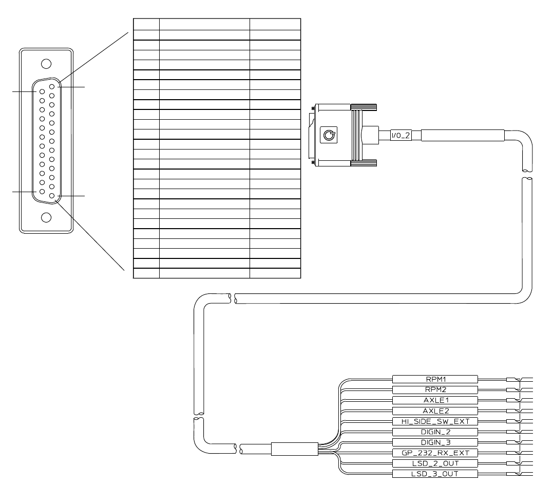
Secondary Accessory Cable Connector Pin Callouts Wiring Diagrams and Charts
A-8 MAY CONTAIN U.S. AND INTERNATIONAL EXPORT CONTROLLED INFORMATION 80-J9968-1 Rev. A
DO NOT COPY
Secondary Accessory Cable Connector Pin Callouts
ORN/BLK 22
ORN/BLK 22
ORN/BLK 22ORN/BLK 22
VIO 22
VIO 22
VIO 22VIO 22
BLK/WHT 22
BLK/WHT 22
BLK/WHT 22BLK/WHT 22
GRA 22
GRA 22
WHT/RED 22
WHT/RED 22
WHT/BLK 22
WHT/BLK 22
WHT/BLK 22WHT/BLK 22
WHT/YEL 22
WHT/YEL 22
WHT/YEL 22WHT/YEL 22
WHT 22
WHT 22
WHT 22WHT 22
BLU/WHT 22
BLU/WHT 22
BLU/WHT 22BLU/WHT 22
GRN/WHT 22
GRN/WHT 22
GRN/WHT 22GRN/WHT 22
09AAA_015
PIN SIGNAL COLOR
(RPM1)(RPM1)
(RPM1)
1010
10
1111
11
1212
12
(RPM2)(RPM2)
(RPM2)
2323
23
2222
22
2121
21
2020
20
1919
19
1818
18
1717
17
1616
16
1515
15
2424
24
(AXLE1)(AXLE1)
(AXLE1)
(AXLE2)(AXLE2)
(AXLE2)
WHT/RED 22WHT/RED 22(HI_SIDE_SW_EXT)(HI_SIDE_SW_EXT)11
(DIGIN_2)(DIGIN_2)2
2
4
4
5
5
6
6
7
7
8
8
9
9
(GP_232_RX_EXT)(GP_232_RX_EXT)
(GP_232_RX_EXT)
1414
14
(DIGIN_3)(DIGIN_3)
(DIGIN_3)
2525
25
(LSD_2_OUT)(LSD_2_OUT)
(LSD_2_OUT)
1313
13
(LSD_3_OUT)(LSD_3_OUT)
(LSD_3_OUT)
3
13
14 1
25
GRA 22
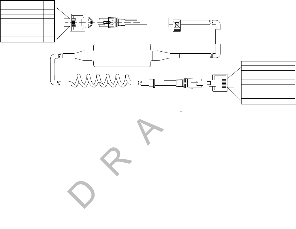
80-J9968-1 Rev. A MAY CONTAIN U.S. AND INTERNATIONAL EXPORT CONTROLLED INFORMATION A-9
Wiring Diagrams and Charts Display Interface Unit 200 (DIU200) Cable Connector Pin Callouts
DO N OT
COPY
Display Interface Unit 200 (DIU200) Cable Connector Pin Callouts
MAS MAS
MAS
DIU PORTDIU PORT
DIU PORT
1
8
1
8
09AAA_017
PINSIGNAL
1
2
3
4
5
6
7
8
COLOR
Green
Yellow
Blue
Violet
Orange
Gray
Black
Red
(LVDS+)(LVDS+)
(LVDS+)
(GND)(GND)
(GND)
(LVDS-)(LVDS-)
(LVDS-)
(GND)(GND)
(GND)
(V+)(V+)
(V+)
(V+)(V+)
(V+)
(USB+)(USB+)
(USB+)
(USB-)(USB-)
(USB-)
(LVDS+)(LVDS+)
(LVDS+)
(GND)(GND)
(GND)
(LVDS-)(LVDS-)
(LVDS-)
(GND)(GND)
(GND)
(V+)(V+)
(V+)
(V+)(V+)
(V+)
(USB+)(USB+)
(USB+)
(USB-)(USB-)
(USB-)
1
2
3
4
5
6
7
8
PIN
SIGNAL
COLOR
Green
Yellow
Blue
Violet
Orange
Gray
Black
Red
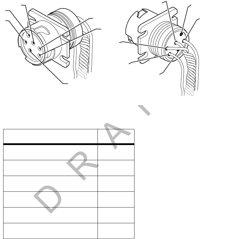
Six-pin Data Link Connector Pin Callouts Wiring Diagrams and Charts
A-10 MAY CONTAIN U.S. AND INTERNATIONAL EXPORT CONTROLLED INFORMATION 80-J9968-1 Rev. A
DO NOT COPY
Six-pin Data Link Connector Pin Callouts
SIGNAL PIN
J1708/J1587 DATA LINK+ A
J1708/J1587 DATA LINK- B
+12VDC C
PLUG P/N:23507136 D
BATTERY GROUND E
PLUG P/N:23507136 F
AA
C
C
D
D
B
B
FF
EE
08AAA_05
0
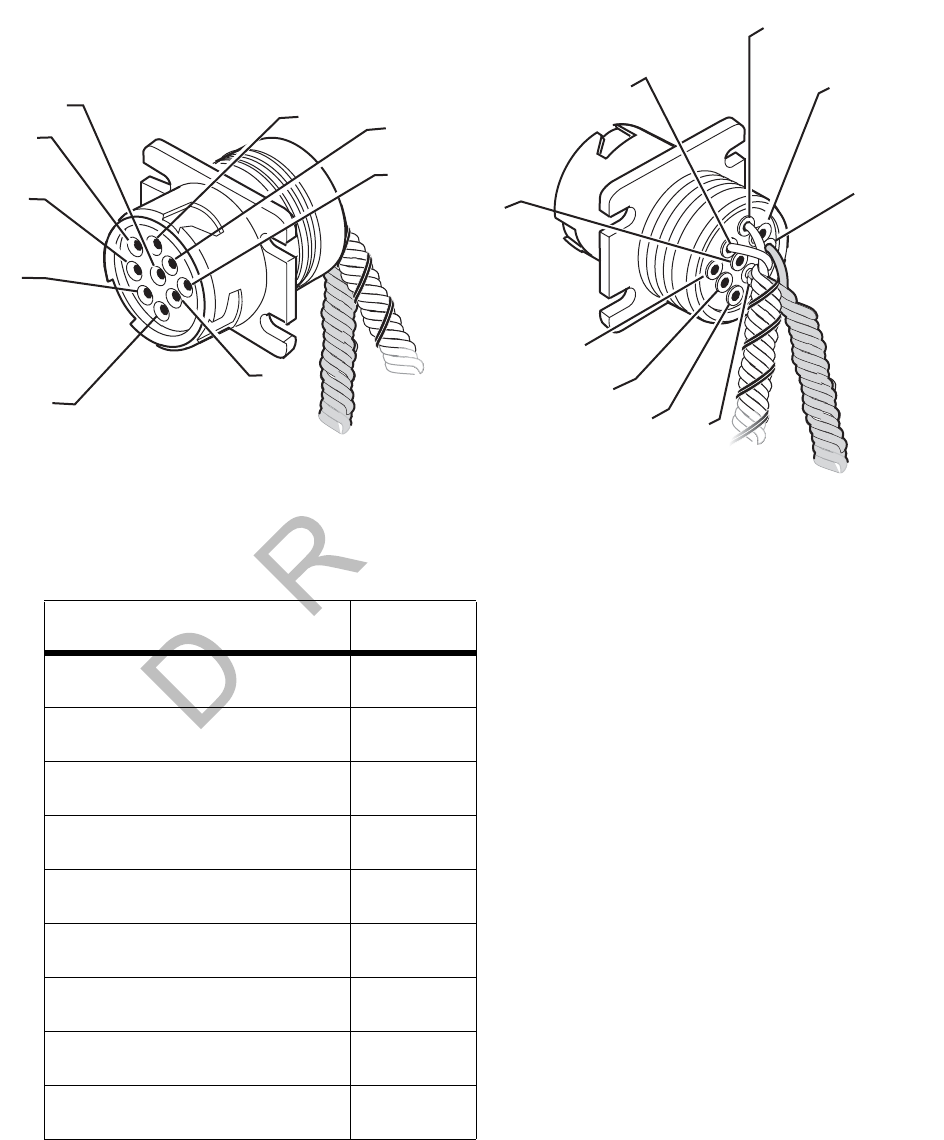
80-J9968-1 Rev. A MAY CONTAIN U.S. AND INTERNATIONAL EXPORT CONTROLLED INFORMATION A-11
Wiring Diagrams and Charts Nine-pin Data Link Connector Pin Callouts
DO N OT
COPY
Nine-pin Data Link Connector Pin Callouts
SIGNAL PIN
BATTERY GROUND A
+12VDC B
J1939 DATA LINK+ C
J1939 DATA LINK- D
J1939 SHIELD E
J1708/J1587 DATA LINK+ F
J1708/J1587 DATA LINK- G
PLUG H
PLUG J
J
D
E
C
F
B
A
G
H
08AAA_051
A
C
D
B
F
E
J
G
H
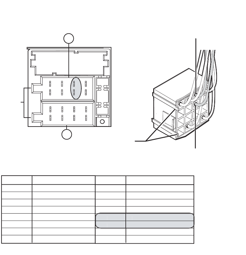
Radio Connector Pin Callouts Wiring Diagrams and Charts
A-12 MAY CONTAIN U.S. AND INTERNATIONAL EXPORT CONTROLLED INFORMATION 80-J9968-1 Rev. A
DO NOT COPY
Radio Connector Pin Callouts
Front Drivers Side
Speaker Wire (B6)
Note: Connector tabs
on this side
06AAA_179A
Front Drivers Side
Speaker Wire (B5)
1
2
3
7
8
4
1
2
3
5
7
8
4
6
5
6
Notches
PIN SIGNAL
A1
A2
A3
A4
A5
A6
A7
A8
N/C
N/C
PARK LIGHTS
IGN CONTACT
PWR ANT OUTPUT
PWM/ANALOG DIM
BATTERY - MAIN
GROUND
PIN SIGNAL
B1
B2
B3
B4
B7
B8
RR + SPEAKER
RR - SPEAKER
RF + SPEAKER
RF -
S
PEAKE
R
LR + SPEAKER
LR - SPEAKER
B
5
B
6
LF +
S
PEAKE
R
LF -
S
PEAKE
R
A
B
Common Radio and Harness
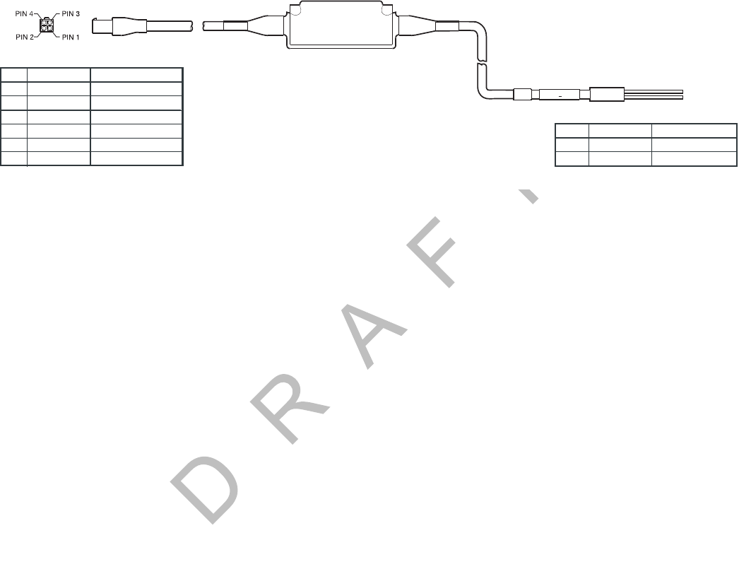
80-J9968-1 Rev. A MAY CONTAIN U.S. AND INTERNATIONAL EXPORT CONTROLLED INFORMATION A-13
Wiring Diagrams and Charts CAN Conductor Cable Pin Callouts
DO N OT
COPY
CAN Conductor Cable Pin Callouts
CAN BUSCAN BUSCAN BUS
P1
SIGNAL COLOR
P
SIGNAL COLOR
1
2
CAN_B (TX)
CAN_H
CAN_L
CAN_A (RX)
CAN_D (PWR)
CAN_C (GND)
ORANGE / BLACK 24
BLACK / ORANGE 24
BLACK / BLUE 24
BLUE / BLACK 24
BLACK / RED 223
BLACK 224
YELLOW
GREEN
08AAA_045

CAN Conductor Cable Pin Callouts Wiring Diagrams and Charts
A-14 MAY CONTAIN U.S. AND INTERNATIONAL EXPORT CONTROLLED INFORMATION 80-J9968-1 Rev. A
DO NOT COPY

80-J9968-1 Rev. A MAY CONTAIN U.S. AND INTERNATIONAL EXPORT CONTROLLED INFORMATION B-1
DO NOT COPY
B
Environmental and Power Requirements
Topics in this appendix provide environmental and power requirements for the Qualcomm®
mobile computing platform 200 (MCP200) and accessories.
MCP200 Environmental and Power Requirements . . . . . . . . . . . . . . . . . . . . . . . . . B-2
For technical questions, contact Qualcomm Enterprise Services (QESSM) Customer Support.
Customer Support is staffed 24 hours a day, 365 days a year:
In the United States, call 800-541-7490
In Canada, call 800-863-9191

MCP200 Environmental and Power Requirements Environmental and Power Requirements
B-2 MAY CONTAIN U.S. AND INTERNATIONAL EXPORT CONTROLLED INFORMATION 80-J9968-1 Rev. A
DO NOT COPY
MCP200 Environmental and Power Requirements
Condition Requirement
Extended Operating Temperature -40° C to 70° C (-40° F to 158° F)
Vibration/Shock Mobile application server 200 (MAS200)
does not have a shock tray.
Neither the wireless data box 200 (WIB200)
nor optional satellite data modem (SDM)
should be mounted to any member/support
directly connected to the chassis, such as a
headache rack.
Humidity
WIB200
MAS200
Display interface unit 200 (DIU200)
Optional SDM
Not watertight. DO NOT get wet.
Not watertight. DO NOT get wet.
Not watertight. Turn over immediately if
liquids are spilled on it.
Weatherproof.
Power +9 to +32 Volts DC
Operating at +12V. MCP200 draws a maximum of 1.12 amps.
Operating at +12V using optional RCD and
speaker switch cable only—no accessories. MCP200 draws a maximum of 1.6 amps
from the battery (12 W).
Asleep. MCP200 draws 110 mA.
Asleep using optional RCD and speaker
switch cable only—no accessories. MCP200 draws 110 mA.
Using optional SDM
Operating at +12V. MCP200 draws a maximum of 1.5 amps.
Operating at +12V using optional RCD and
speaker switch cable only—no accessories. MCP200 draws a maximum of 1.8 amps
from the battery (24 W).
Asleep. MCP200 draws 60–70 mA.
Asleep using optional RCD and speaker
switch cable only—no accessories. MCP200 draws 60–70 mA.

80-J9968-1 Rev. A MAY CONTAIN U.S. AND INTERNATIONAL EXPORT CONTROLLED INFORMATION C-1
DO NOT COPY
C
Standard RMA Procedure
Topics in this appendix provide Qualcomm’s standard Return Material Authorization (RMA)
procedure and policies for use in the United States only. It applies to current Qualcomm
Enterprise Services (QESSM) products that need to be returned for replacement. For
information on the GlobalTRACS® RMA procedure, refer to GlobalTRACS® Standard RMA
Procedure, 80-J5638-1.
The Return Material Authorization Process . . . . . . . . . . . . . . . . . . . . . . . . . . . . . . . C-1
How to Obtain an RMA Number. . . . . . . . . . . . . . . . . . . . . . . . . . . . . . . . . . . . . . . . C-2
RMA Policies . . . . . . . . . . . . . . . . . . . . . . . . . . . . . . . . . . . . . . . . . . . . . . . . . . . . . . C-4
This document does not cover equipment problem diagnosis. For technical assistance,
please refer to the current diagnostic or installation guide. Listings of manuals and ordering
information may be obtained at our web site at qes.qualcomm.com.
The Return Material Authorization Process
RMAs are used whenever equipment must be returned. They authorize, schedule, and track
the return, repair or replacement, and shipment of equipment.
The RMA process involves three separate events:
• You request an RMA number.
• Qualcomm arranges shipment of a replacement component to you.
• You return a failed component to the address specified by Qualcomm.
The RMA process is started when you request an RMA number. The RMA number is a
reference number that is used to track the status of each part as it moves through the RMA
process. After you are issued the RMA number, a replacement part will be shipped to you.
You are responsible for returning the defective equipment to the address specified by
Qualcomm within 14 days.

How to Obtain an RMA Number Standard RMA Procedure
C-2 MAY CONTAIN U.S. AND INTERNATIONAL EXPORT CONTROLLED INFORMATION 80-J9968-1 Rev. A
DO NOT COPY
How to Obtain an RMA Number
There are two ways to obtain an RMA number:
• Visit our web site at qes.qualcomm.com and then log into iQ. See Creating an RMA On-
line on page C-4. Access for customers only.
• Call Qualcomm Enterprise Services Customer Support at (800) 541-7490 and request an
RMA number.
Our web site provides customers with forms and the option for RMAs on-line. If you call QES
Customer Support between 6:00 a.m. and 5:00 p.m. Pacific Time, Monday through Friday,
you can be issued an RMA number over the phone.
Required Information
Before the RMA number can be issued, you need to provide Qualcomm with the following
information.
Date. The date that you are sending the form to Qualcomm.
Customer Name and Contact. The name of the company that is requesting the RMA and
the name of the person making the RMA request.
“Ship to:” Address. The complete address where the replacement component is to be
shipped, plus the name of the person to whose attention the package should be addressed.
Delivery Priority. All replacements are typically shipped within 48 hours (two business
days). If you require 24-hour delivery, you will need to include your shipper account number.
(This is your FedEx or UPS account number.) The cost of shipping for 24-hour delivery will be
billed to your shipper account number.
Return Code. The code that best describes the reason you are returning the unit. Frequently
used codes include:
CD Customer Damage. Any damage that occurred due to improper or negligent use of the
equipment by the customer. Customer damage may be caused by an accident, incorrect
installation, mishandling, or intentional abuse. A purchase order number is required in order to
process a customer damage RMA.
DOA Dead on Arrival. A component is considered DOA if it fails to function when taken out of the
box at installation.
FF Field Failure. A working unit that has failed in the field after installation.
OE Order Error. Receipt of wrong parts or of parts not ordered.
SE Shipping Error. The correct part was ordered but the wrong part was received.
UP Upgrade. The return of a working unit for an upgraded model. Upgrades can be made to
software or hardware. Use of this return code requires a contractual amendment and a
purchase order number.

80-J9968-1 Rev. A MAY CONTAIN U.S. AND INTERNATIONAL EXPORT CONTROLLED INFORMATION C-3
Standard RMA Procedure Required Information
DO N OT
COPY
Truck or Vehicle Number. The number of the truck, tractor, or item on which the component
was installed.
Unit ID (System Serial Number). The identification number of the mobile system which is
required to verify correct ownership of the system. To find the number, press the Down
Arrow key on the display screen and look for the Unit Serial Number, or read the serial
number on the main communication unit. This number is also used to determine warranty
status of the unit.
Part Number (Product ID/MCN). Due to the multiple variations of Qualcomm equipment, the
part number—Material Control Number (MCN)—must be provided to ensure that the correct
replacement part is shipped. Be sure to verify the part number by looking at the actual part
being returned, not by checking a pre-defined parts list. For an MVPc™ unit, use the model
number.
Failed Serial Number. A serial number (S/N) is required for each serialized component on
an RMA. The major serialized components include:
• MCT Communication Unit, IMCT Antenna Communication Unit, TruckMAIL™ Mobile
Messaging Terminal, OmniExpress® Terrestrial Communication Unit, T2™ Unit,
Qualcomm MAS, Qualcomm TDM
• Outdoor Unit, Qualcomm SDM
• MVPc unit, DU/EDU, Qualcomm MDU
• Some PC components
The serial number decal is affixed to the component chassis. (Always include the leading
zeros in a serial number.)
Replacement Serial Number. The serial number (S/N) of the unit that was installed to
replace the failed part listed on the RMA. (Always include leading zeros in a serial number.)
Purchase Order. A purchase order (P.O.) number may be required when an item is customer
damaged or when you are requesting an upgrade. Companies may also require a P.O. when
products have an RMA at an authorized Qualcomm Service Center.
Failure Description. A complete description of the problem associated with the failed
component. Please be specific. Qualcomm needs as much information as possible to
effectively duplicate the failure, diagnose the problem, and repair the failed unit. It is better to
give too much information than not enough information. Descriptions such as “Unit not
operating” or “Not working” do not provide enough information.
Work Order (WO) Number (for Service Centers only). This number only applies if the
repair is being performed at an authorized Qualcomm Service Center. If the repair is done at
a service center, the shipped replacement unit will be sent to the service center instead of to
the customer.

Creating an RMA On-line Standard RMA Procedure
C-4 MAY CONTAIN U.S. AND INTERNATIONAL EXPORT CONTROLLED INFORMATION 80-J9968-1 Rev. A
DO NOT COPY
Creating an RMA On-line
Depending on the program you are using, you may create an RMA on-line. You can cancel
the RMA at anytime during the procedure. You can also see a list of tips in various parts of the
web site. This is for customers only.
1. Log on to qes.qualcomm.com. You will see the iQ web site.
2. Enter your name and password then click Log in.
3. Click the Returns and Warranties tab.
4. Click Create an RMA.
5. Follow the instructions provided on this web site.
RMA Policies
What to Return/Not Return
Normally, all failed equipment must be returned for repair or replacement. The following major
system components need to be returned:
• MCT Communication Unit (Comm Unit)
• IMCT Antenna Communication Unit (ACU)
• TruckMAIL Mobile Messaging Terminal (MMT)
• OmniExpress Terrestrial Communication Unit (TCU)
• Qualcomm Mobile Application Server (MAS)
• Outdoor Unit (ODU)
• Qualcomm Satellite Data Modem (SDM)
• Qualcomm Terrestrial Data Modem (TDM)
• MVPc unit
• Display Unit/Enhanced Display Unit (DU/EDU)
• Qualcomm Media Display Unit (MDU)
• T2 Unit
• 7-Way tool
• Major PC components
• Any Dead on Arrival (DOA) component

80-J9968-1 Rev. A MAY CONTAIN U.S. AND INTERNATIONAL EXPORT CONTROLLED INFORMATION C-5
Standard RMA Procedure Where to Return Equipment
DO N OT
COPY
There are a few exceptions to this policy. You are not required to return the following
components unless they are Dead on Arrival.
• All cables
• Pager System Components (receiver, transmitter, and antenna)
• Panic Button
• Remote Message Waiting Light (RMWL)
• Buzzer/Switch Kit
• Antennas (i.e., GPS, cellular, or Loran)
• Dual Signal Multiplier
•MPG Display
• TrailerTRACS® Transmitter
• T2 external battery—DO NOT return to Qualcomm unless specifically requested by a
Qualcomm representative. Proper disposal of defective or dead lead-acid batteries is the
responsibility of the T2 owner/customer. Please dispose of defective or dead batteries at a
local lead-acid battery recycling center.
• Qualcomm Remote Control Device (RCD)
• Qualcomm MAS battery—DO NOT return to Qualcomm unless specifically requested by a
Qualcomm representative. Proper disposal of defective or dead lead-acid batteries is the
responsibility of the Qualcomm MCP owner/customer. Please dispose of defective or dead
batteries at a local lead-acid battery recycling center.
Any components that are found to be Dead on Arrival (DOA) within 90 days of shipment,
including cables and antennas, must be returned to Qualcomm for failure analysis. If
available, please provide the Lot Date Code for the defective component when you request
the RMA. If possible, return the defective component in its original packaging.
Where to Return Equipment
Please return equipment to Qualcomm at the following address. Make sure that the RMA
number is marked clearly on the outside of the box.
QUALCOMM Incorporated
5995 Pacific Center Blvd., Suite# 103
San Diego, CA 92121
RMA #: __________________
(800) 541-7490
To prevent damage during shipment and handling, carefully package all equipment being
returned. If the original shipping container and packing material are available, please use
them to return the equipment.

“Past Due” Equipment Standard RMA Procedure
C-6 MAY CONTAIN U.S. AND INTERNATIONAL EXPORT CONTROLLED INFORMATION 80-J9968-1 Rev. A
DO NOT COPY
“Past Due” Equipment
Qualcomm’s standard policy is to “advance replace” equipment when the RMA number is
issued. This means that a replacement component will be shipped before the defective
component is received at Qualcomm. Customers are responsible for returning the failed
equipment to Qualcomm within fourteen (14) days after receiving the RMA number.
If the failed items are not received within this time period, Qualcomm may invoice the
customer for the higher of the current price or the applicable spare part price for the
component. In addition, customers with “past due” equipment will be notified that Qualcomm
will discontinue its “advance replace” RMA policy and future RMAs will be considered “no
advance replace.” This means that a replacement component will not be shipped until the
defective component is received at Qualcomm. When all the past due components are
received by Qualcomm or paid in full, Qualcomm may resume advance replacement of failed
equipment. Certain upgrade programs may be structured as no advance replace.
Customer-Damaged Equipment
Customer-damaged items are those which have been damaged as a result of improper or
negligent use of the equipment. This can include accidental damage, incorrect installation,
mishandling, or intentional abuse. Customer-damaged equipment must be identified at the
time the RMA is requested.
If an RMA item cannot be repaired, it will be declared “scrap.” The “scrap” determination will
be made if the cost of repairing the item exceeds the cost of replacing it.
Types of damage that usually result in major system components being scrapped are crushed
components; internal corrosion of components; fire damage to components; and cracked
housing of components.
Caution
Never open the Communication Unit; MAS; TDM; or ODU, ACU, and SDM antennas.
Breaking the seal on these components voids their warranties, causing them to be
treated as customer-damaged items.
(Exceptions to this include opening the Antenna radome for maintenance; opening the
Communication Unit for EPROM upgrades; and opening the MAS to test or replace the
battery.)
Missing, Lost, Stolen, or Destroyed Equipment
It is not necessary to obtain an RMA number for missing, lost, stolen, or destroyed equipment
since nothing will be returned to Qualcomm. Replacements for missing, lost, stolen, or
destroyed equipment should be ordered through Sales Administration as spare parts. P.O.
numbers are required for all spare parts orders.
If the missing, lost, stolen, or destroyed equipment includes an MCT Communication Unit,
IMCT Antenna Communication Unit, TruckMAIL Mobile Messaging Terminal, OmniExpress

80-J9968-1 Rev. A MAY CONTAIN U.S. AND INTERNATIONAL EXPORT CONTROLLED INFORMATION C-7
Standard RMA Procedure Permanent Fleet Size Reduction Request Form
DO N OT
COPY
Terrestrial Communication Unit, or Qualcomm Mobile Application Server and a replacement
is not required, you should submit a “Fleet Size Reduction Request Form.” This form is
shown on the next page.
For Service Centers only: If equipment is missing at the time of installation, indicate this when
you request equipment and you will be issued a Sale number instead of an RMA number.
Permanent Fleet Size Reduction Request Form
This form (shown on the following page) should be used to permanently decrease the size of
your OmniTRACS® fleet in the event that a Comm. Unit is permanently lost, stolen, or
destroyed. Submitting this form will ensure that your base message charges and extended
maintenance billing (if applicable) are adjusted appropriately.

Permanent Fleet Size Reduction Request Form Standard RMA Procedure
C-8 MAY CONTAIN U.S. AND INTERNATIONAL EXPORT CONTROLLED INFORMATION 80-J9968-1 Rev. A
DO NOT COPY
Permanent Fleet Size Reduction Request Form
To: Customer Support AdministrationFacsimile: (858) 658-1598
From:___________________________________________(Print Customer Name)
Phone number:___________________Fax number:___________________
____________________________________________________________________
This form should be used only if you would like to PERMANENTLY** decrease your delivered
fleet size. Your delivered fleet size is determined based on the number of complete systems,
i.e., MCT, IMCT, TruckMAIL, OmniExpress, or Qualcomm MCP (collectively referred to as
“Unit”), purchased and automatically increases incrementally with the purchase of each new
Unit. The shipment of spare components, such as the shipment of an IMCT Antenna
Communication Unit or a MCT Communication Unit (collectively referred to as “Hardware
Messaging Units”), will not increase your delivered fleet size value. Your delivered fleet size
value is used to calculate base message charges and extended maintenance charges (if
applicable). If a customer does not notify Qualcomm by completing and signing this
“Permanent Fleet Size Reduction Request Form,” these charges per Unit will continue. You
may reduce your fleet size if one of the following occurs:
A Hardware Messaging Unit (i.e., an MCT Communication Unit, an IMCT Antenna
Communication Unit, a TruckMAIL Mobil Messaging Terminal, an OmniExpress Terrestrial
Communication Unit, or an Qualcomm Mobile Application Server) is destroyed, stolen, or lost
and you elect not to replace it via an RMA or a sales order for a spare Hardware Messaging
Unit. In this situation, the salvageable components are put into spares stock.
A Unit (i.e., a complete system) is destroyed, stolen, or lost, and you elect to purchase a
replacement Unit via a sales order, since the shipment of a Unit will automatically increase
your delivered fleet size value.
A Component of a Unit (other than the Hardware Messaging Unit, i.e., Outdoor Unit, or
MVPC) is destroyed, stolen, or lost and you want to accurately reflect the components
currently existing in your fleet for warranty and/or extended maintenance purposes.
** NOTE: ONCE A FLEET SIZE REDUCTION REQUEST FORM IS SIGNED BY
CUSTOMER AND RECEIVED BY QUALCOMM, THE COMPONENT(S) SET FORTH WILL
BE PERMANENTLY REMOVED FROM QUALCOMM’s NETWORK MANAGEMENT
FACILITY COMPUTER AND WILL NOT BE RECREATED.
To PERMANENTLY decrease your fleet size, fill in the lower part of this worksheet and fax
copies to Customer Support Administration using the above fax number. Qualcomm will
contact you upon completion.
Customer:________________________________ Truck Number:____________
Communication Unit Serial Number (IMCT ID):_______________________________
Equipment was ___stolen ___lost __destroyed ___other (please check one).

80-J9968-1 Rev. A MAY CONTAIN U.S. AND INTERNATIONAL EXPORT CONTROLLED INFORMATION D-1
DO NOT COPY
D
Upgrading the Qualcomm® MCP Using Secure Digital Cards
An MCP is normally upgraded with software by sending it over-the-air using satellite
transmissions. However, there may be occasions when upgrades are necessary using
secure digital (SD) cards, for example, when there is an operating system (OS) upgrade and
when upgrades need to be performed very quickly.
Topics in this appendix provide specific instructions for checking the software versions
installed on the Qualcomm® MCP and upgrading the MCP using SD cards.
Checking the Software Versions Installed . . . . . . . . . . . . . . . . . . . . . . . . . . . . . . . . . . . .D-2
SD Card Instructions . . . . . . . . . . . . . . . . . . . . . . . . . . . . . . . . . . . . . . . . . . . . . . . . . . . .D-3
Upgrading Only the MAS Software . . . . . . . . . . . . . . . . . . . . . . . . . . . . . . . . . . . . . . . . .D-3
Upgrading the MAS Operating System and MAS Software. . . . . . . . . . . . . . . . . . . . . . .D-5
Upgrading the SDM Software . . . . . . . . . . . . . . . . . . . . . . . . . . . . . . . . . . . . . . . . . . . . .D-5
Upgrading the MDU Software . . . . . . . . . . . . . . . . . . . . . . . . . . . . . . . . . . . . . . . . . . . . .D-6
For technical questions, contact Qualcomm Enterprise Services (QESSM) Customer Support.
Customer Support is staffed 24 hours a day, 365 days a year:
In the United States, call 800-541-7490
In Canada, call 800-863-9191
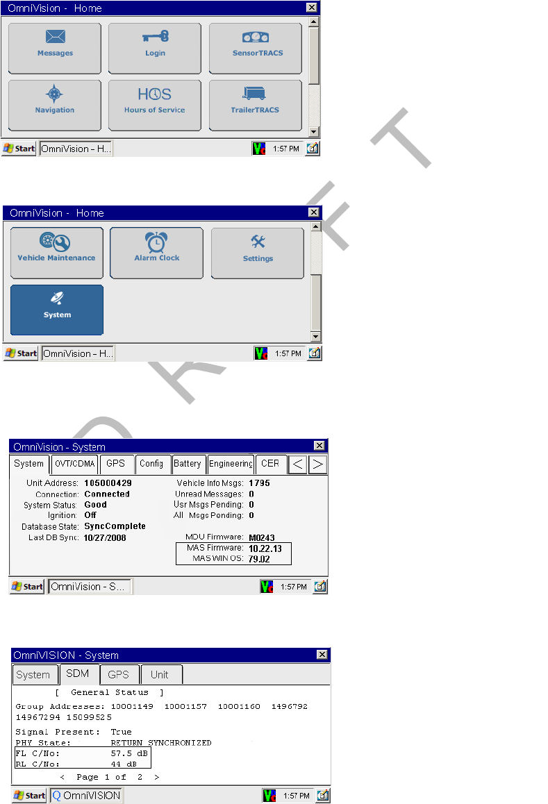
Checking the Software Versions Installed Upgrading the Qualcomm® MCP Using Secure Digital Cards
D-2 MAY CONTAIN U.S. AND INTERNATIONAL EXPORT CONTROLLED INFORMATION 80-J9968-1 Rev. A
DO NOT COPY
Checking the Software Versions Installed
Shortly after you power up the MCP, the user interface screen displays.
1. Scroll down to the System icon and touch the icon.
2. Touch the System tab to access system information about the MCP.
• MAS, MAS Win OS, SDM, and MDU firmware version numbers are listed here.
3. Touch the SDM tab to access the SDM version.
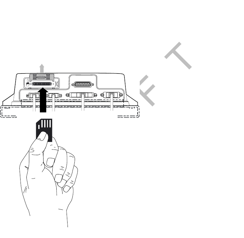
80-J9968-1 Rev. A MAY CONTAIN U.S. AND INTERNATIONAL EXPORT CONTROLLED INFORMATION D-3
Upgrading the Qualcomm® MCP Using Secure Digital Cards SD Card Instructions
DO N OT
COPY
SD Card Instructions
• Most brands of SD card work with the MCP.
- Use a 1 GB SD card to load software.
• The SD card must always be inserted into the SD card slot in the MAS with label side
down/metal strips facing up.
• Organize files on the SD card so the MAS can read them.
- Software is available on the iQ/iQSC website, or you can check with a Qualcomm
representative for more information on where to get the software and how the files
need to be organized.
Upgrading Only the MAS Software
MAS should be powered ON, ignition ON.
1. Insert MAS SW SD card into slot on MAS with label side down/metal strips facing up.
• Soon after the MAS SW card is installed, the MDU screen will display, “Verifying
component: xxx of XXY.”
• Approximately one minute after the SD card is inserted, the process writes data to
memory and reboots itself.
• Once the unit comes back up after the reboot, the MDU screen shows “Upgrading
components: xxx of XXY.” This takes about five minutes.
05AAA_222X5
DSPL SDM I / 0
UI
PWR
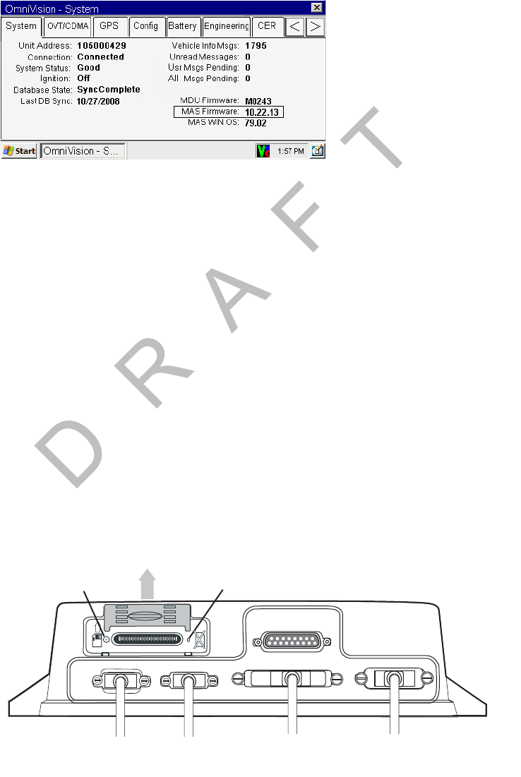
Upgrading the MAS Operating System and MAS Software Upgrading the Qualcomm® MCP Using Secure Digital Cards
D-4 MAY CONTAIN U.S. AND INTERNATIONAL EXPORT CONTROLLED INFORMATION 80-J9968-1 Rev. A
DO NOT COPY
2. After the upgrade process finishes and the MDU screen shows the application icons or
the driver warning screen, remove the SD card and confirm the upgrade is complete by
checking the MAS software version on the System Information screen.
Upgrading the MAS Operating System and MAS Software
Note
If the MAS OS is upgraded, the MAS SW will also need to be upgraded. Before starting an
upgrade, ensure you have SD cards for the MAS operating system and the MAS software.
1. You must disconnect power for 10 minutes or until all LEDs go out.
2. Insert the SD card labelled, MAS Operating System, with label side down/metal strips
facing up.
3. Ensure the MAS internal battery is installed and connected.
4. Apply external power by connecting the power cable to the MAS. Vehicle ignition should
be ON.
5. Normal upgrade indicators are:
• LED to the left of the SD card slot blinks green (downloading).
• LED to the right of the SD card slot is solid red.
• No MDU screens are typically available for this step.
05AAA_222X1
DSPL SDM I / 0
UI
PWR
Solid REDBlinking GREEN
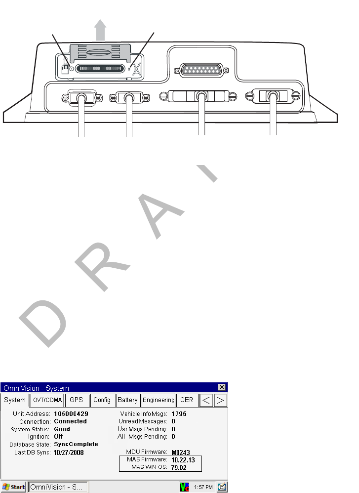
80-J9968-1 Rev. A MAY CONTAIN U.S. AND INTERNATIONAL EXPORT CONTROLLED INFORMATION D-5
Upgrading the Qualcomm® MCP Using Secure Digital Cards Upgrading the SDM Software
DO N OT
COPY
6. Keep MAS OS SD card in slot until the right LED goes to solid green. When the right
LED is solid green, the OS upgrade is complete. This should take about 3–5 minutes.
7. Remove MAS OS SD card and quickly replace with MAS SW SD card, with label side
down/metal strips facing up.
8. After approximately one minute, normal upgrade indicators are:
• LED to the left of the SD card slot is blinking green.
• MDU screen shows, PLEASE WAIT, LOADING.
9. Keep the MAS SW SD card in the slot until the MDU screen shows the application icons
or the driver warning screen. When either of these appears, the upgrade is complete.
Verify the software version on the System screen. This should take 10–15 minutes.
10. Remove the SD card and verify the S/W versions on the System screen.
Note
The S/W versions will not necessarily match those shown on the screen below.
The upgrade is now complete.
Upgrading the SDM Software
1. Ensure the SDM is connected to the MAS.
05AAA_222X
2
DSPL SDM I / 0
UI
PWR
Do not remove MAS OS SD card until right LED displays solid green
Solid GREEN
Blinking GREEN
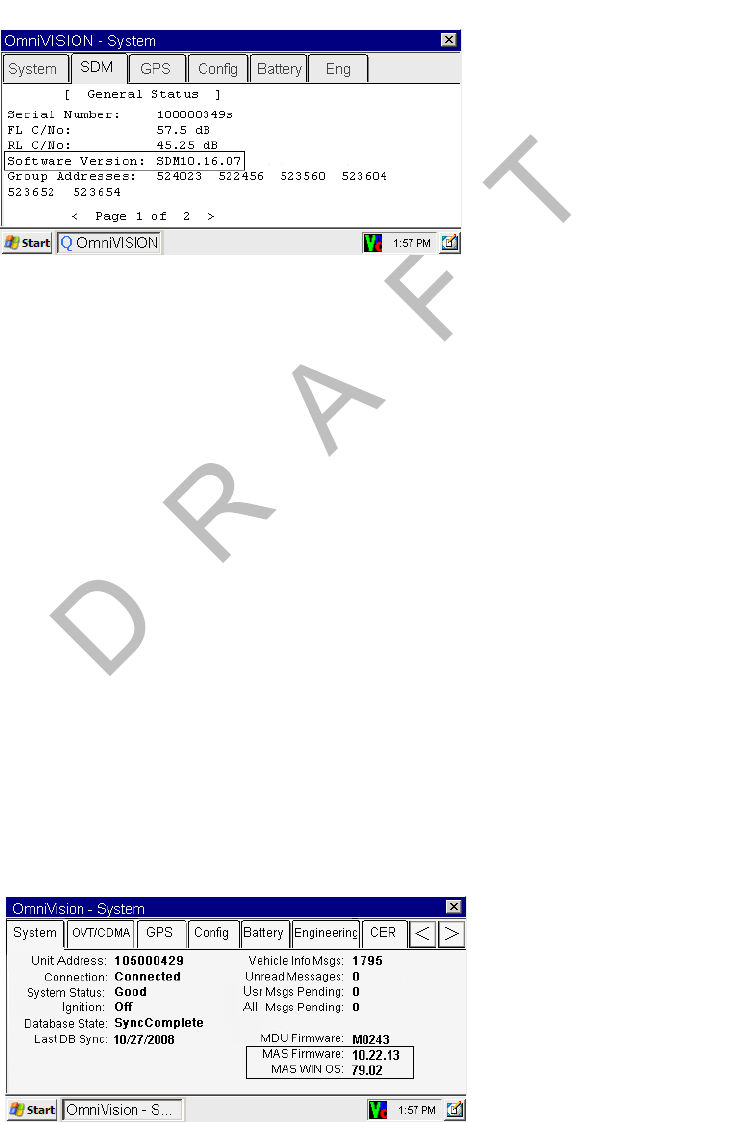
Upgrading the MDU Software Upgrading the Qualcomm® MCP Using Secure Digital Cards
D-6 MAY CONTAIN U.S. AND INTERNATIONAL EXPORT CONTROLLED INFORMATION 80-J9968-1 Rev. A
DO NOT COPY
2. Turn vehicle ignition to ON.
3. Insert SDM SW SD card into slot on MAS with label side down/metal strips facing up.
4. Wait approximately six minutes and then check the SDM software level.
5. Once the SDM software version has updated, remove the SD card.
The upgrade is now complete.
Upgrading the MDU Software
1. Ensure the ignition is ON.
2. Insert SD card into slot on MAS with label side down (metal strips facing up).
3. Approximately 30 seconds later, TTS advises:
• “Setup card is supported. Please remove card and stand by.”
4. Approximately 30 seconds later, TTS advises:
• “Starting to display software update, this will take 5–10 minutes. Please do not turn
off ignition.”
5. Approximately 5–12 minutes later, TTS states:
• “Display software update completed successfully.”
6. Once the upgrade process is complete, you are returned to the last screen you were on
before the upgrade began.

80-J9968-1 Rev. A MAY CONTAIN U.S. AND INTERNATIONAL EXPORT CONTROLLED INFORMATION E-1
DO NOT COPY
E
Preventive Maintenance Inspection
Topics in this appendix provide steps for inspecting the mobile application server 200
(MAS200), the display interface unit 200 (DIU200), the wireless interface box 200 (WIB200),
the optional satellite data modem (SDM), and the TrailerTRACS® system.
How Often Should Inspections Be Performed? . . . . . . . . . . . . . . . . . . . . . . . . . . . . E-2
Inspecting the Mobile Application Server 200 (MAS200). . . . . . . . . . . . . . . . . . . . . E-2
Inspecting the Display Interface Unit 200 (DIU200). . . . . . . . . . . . . . . . . . . . . . . . . E-4
Inspecting the Wireless Interface Box 200 (WIB200) and the Optional Satellite Data Modem (SDM)
E-6
Verifying TrailerTRACS® System Connections . . . . . . . . . . . . . . . . . . . . . . . . . . . . E-9
For technical questions, contact Qualcomm Enterprise Services (QESSM) Customer Support.
Customer Support is staffed 24 hours a day, 365 days a year:
In the United States, call 800-541-7490
In Canada, call 800-863-9191
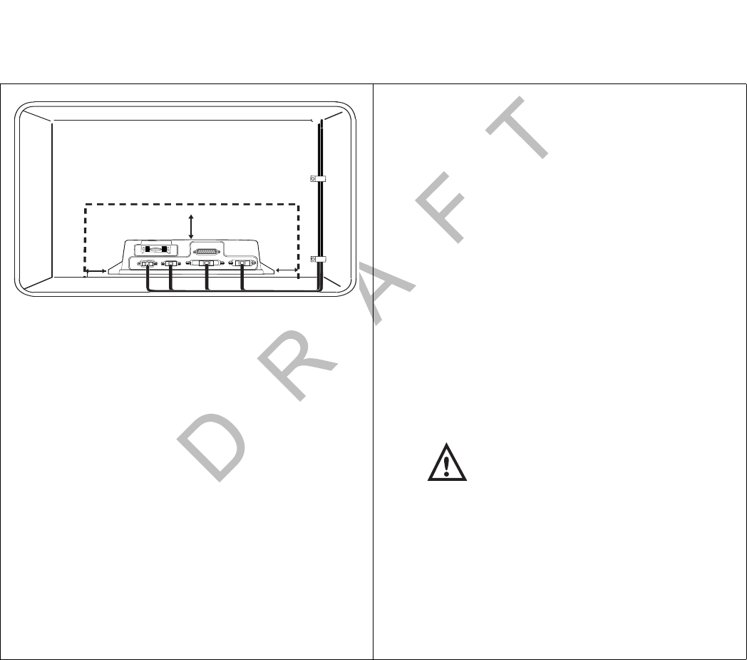
How Often Should Inspections Be Performed? Preventive Maintenance Inspection
E-2 MAY CONTAIN U.S. AND INTERNATIONAL EXPORT CONTROLLED INFORMATION 80-J9968-1 Rev. A
DO NOT COPY
How Often Should Inspections Be Performed?
• Qualcomm® recommends inspections be performed at least once every 90 days.
• During normally scheduled vehicle preventive maintenance inspections.
Inspecting the Mobile Application Server 200 (MAS200)
1. Make sure the compartment where the
MAS200 is installed has at least 1 inch of air
space on each side for cooling and at least 3
inches of space for servicing the backup
battery.
2. Make sure there are 4 to 6 inches of air space
on the connector side to allow for cable bends
and servicing.
3. Make sure tire chains, tools, and other
equipment are not stored on top of the
MAS200.
4. Make sure the mounting hardware holding the
MAS200 in place is tight and does not allow
the MAS200 to vibrate.
Caution
Do not use a pneumatic tool as this could
damage the hardware. Use extreme
caution when working with power tools.
5. Make sure the MCP200 display unit, antenna,
power, and accessory cables coming into the
compartment have enough slack and are not
pulling on the MAS200 connectors. Make sure
the cables are not being chafed or cut by
sharp edges.
1"
1"
3"
DSPL SDM I / 0
UI
PWR
05AAA_237A
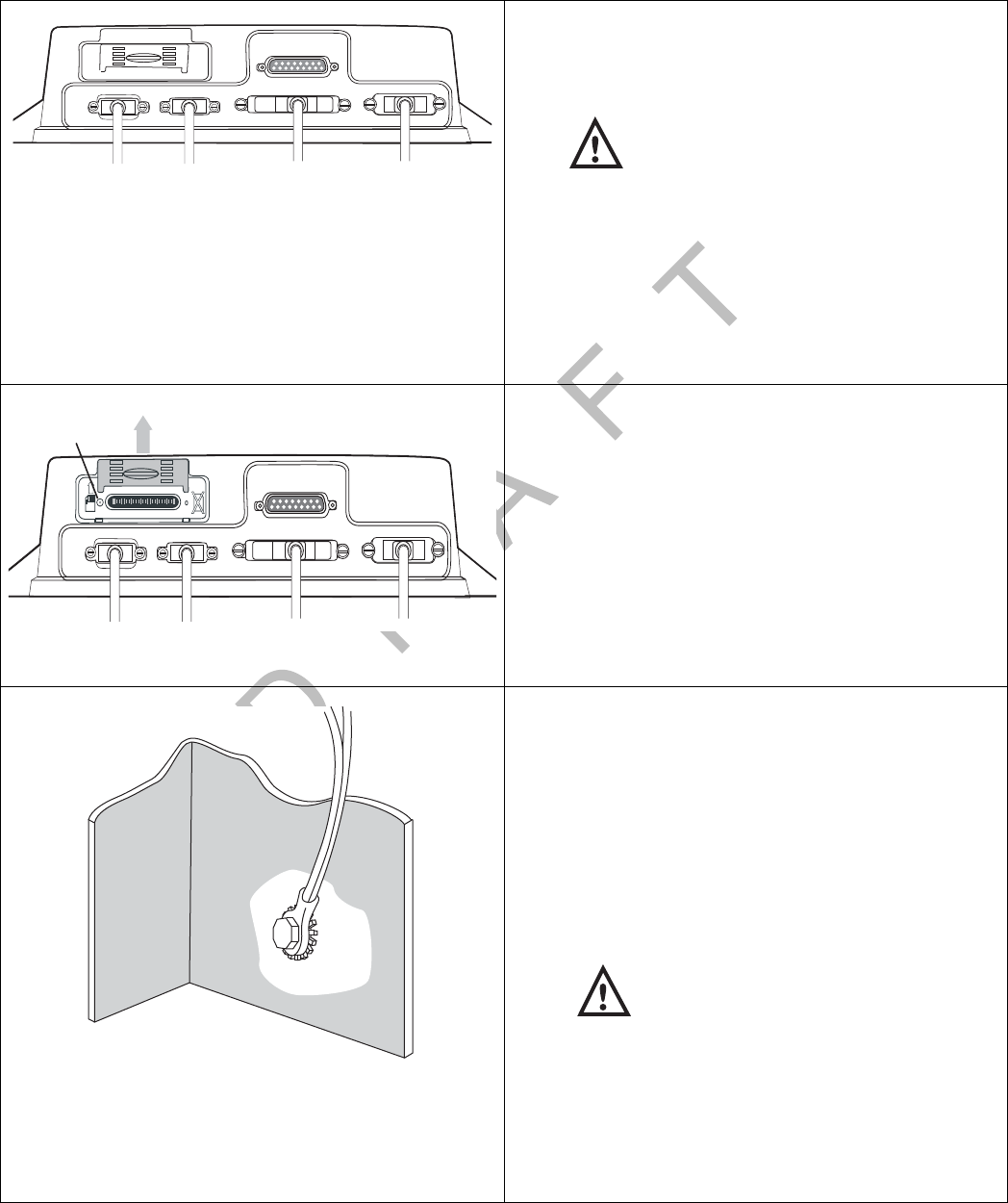
80-J9968-1 Rev. A MAY CONTAIN U.S. AND INTERNATIONAL EXPORT CONTROLLED INFORMATION E-3
Preventive Maintenance Inspection Inspecting the Mobile Application Server 200 (MAS200)
DO N OT
COPY
6. Make sure the cable connectors have not
worked themselves loose from the MAS200.
Hand tighten any loose connectors.
Caution
ONLY hand-tighten or use a small screwdriver on the
connectors.
DO NOT use a pneumatic tool or pliers to tighten the
connectors as this could damage the screws or the
MAS200 mounting tabs.
DO NOT over-tighten.
DO NOT apply grease to the connectors.
7. Check the left side LED indicator on the
MAS200. Normally, the left side LED indicator
will be blinking blue.
Refer to Chapter 13 in the Qualcomm® MCP
200 Series and Accessory Diagnostic Guide
for other LED states.
8. Check to make sure the cables are stored
securely with tie wraps and are stored out of
the way.
9. Check the power connections, such as at the
power distribution panel, to ensure they are
tight and the wiring is secure.
Check all ground connections to make sure
there is a good metal-to-metal contact and the
wires are not strained or damaged. Ground
wires should be attached to vehicle or sleeper
surfaces connected to chassis ground.
Caution
Ground wires should not be connected to
the MAS200 or mounting hardware.
Make sure there is no corrosion around the
ground connection. If there is corrosion, take
the connection apart, clean the connector and
surface with a wire brush, and reconnect the
parts.
05AAA_22
DSPL SDM I / 0
UI
PWR
05AAA_222
DSPL SDM I / 0
UI
PWR
Left Side LED
Metal surface
No
Paint
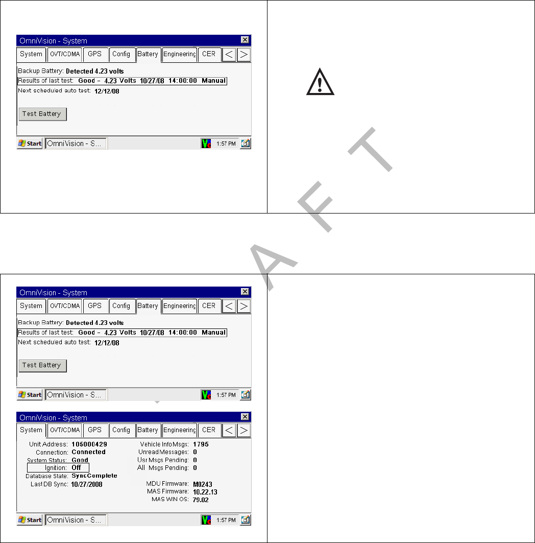
Inspecting the Display Interface Unit 200 (DIU200) Preventive Maintenance Inspection
E-4 MAY CONTAIN U.S. AND INTERNATIONAL EXPORT CONTROLLED INFORMATION 80-J9968-1 Rev. A
DO NOT COPY
Inspecting the Display Interface Unit 200 (DIU200)
10. Go to the Home screen and touch the System
icon. Touch the Battery tab and touch the
Test Battery button.
Warning
It may take a few minutes to perform this
test.
Check the Results of last test and verify that
the battery is Good.
• If the battery shows a failure, Bad—12000,
go to Chapter 16 in the Qualcomm® MCP
200 Series and Accessory Diagnostic
Guide.
1. Verify proper DIU200 operation:
• Turn IGN to the ON position and verify that
the status is Good.
• Turn the IGN to the OFF position and verify
that the status goes to Ignition Off.
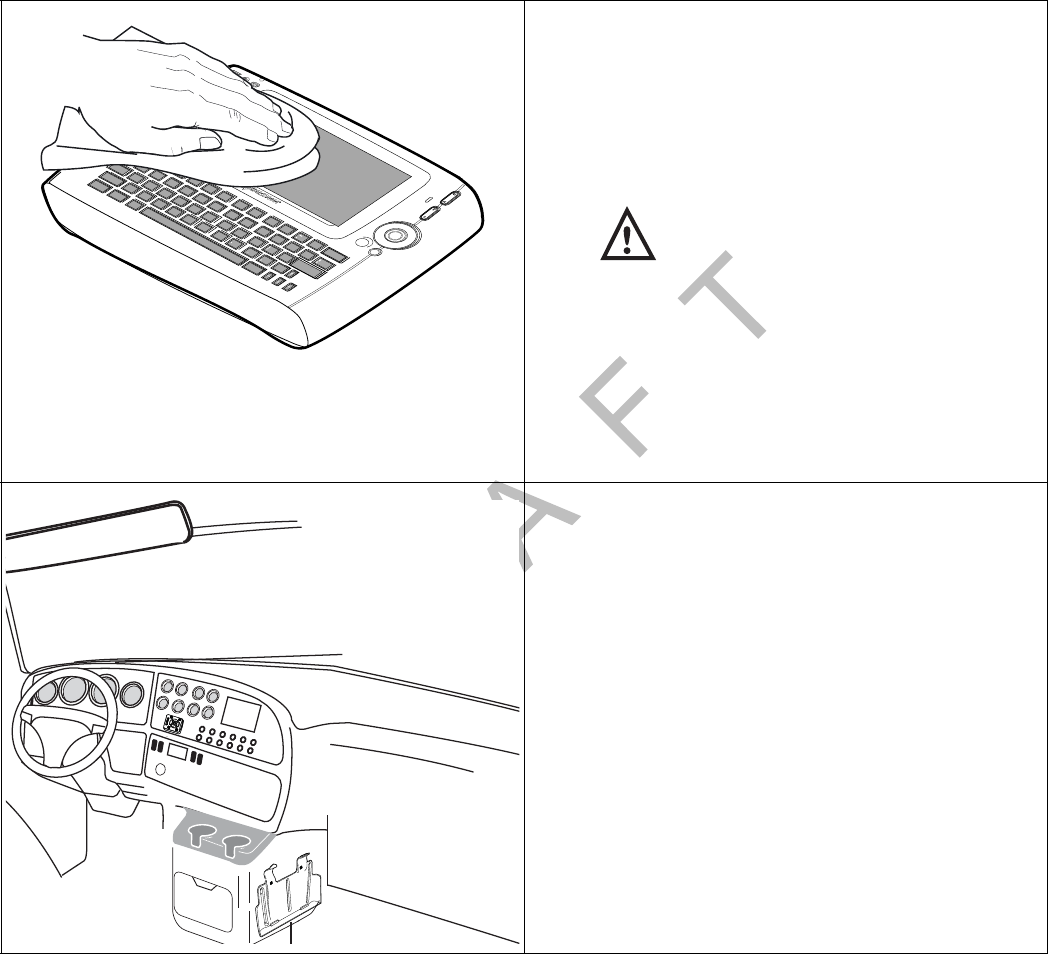
80-J9968-1 Rev. A MAY CONTAIN U.S. AND INTERNATIONAL EXPORT CONTROLLED INFORMATION E-5
Preventive Maintenance Inspection Inspecting the Display Interface Unit 200 (DIU200)
DO N OT
COPY
2. Verify the DIU200 keys and screen are clean.
Qualcomm recommends that you use a soft
cloth and either plain water, glass cleaner, or
mild soap to gently clean the surfaces of the
DIU200 as well as the display screen.
Caution
The MDU is not watertight. Do not spray
any liquid directly on the display screen.
Heavily soiled DIU200s should be returned
to Qualcomm using the RMA process for
proper cleaning.
3. Verify the display screen is readable in any
lighting condition.
4. Make sure the display cable has enough slack
and is not being rubbed or cut by anything
inside the cab.
5. Remove the DIU200 from the holster and
make sure the screws holding the holster in
place are secure.
Esc #
4
$
5
%
6
^
7
&
8
*
9
(
0
)
=
Backspace
+
Tab
0E R T Y U I P
{
[
{
[
Enter
Delete
Shift
LKJHGFD "
'
MN
BVC
V
V
?
!
Opt
Back
1
!!
2
@
3
Q
Caps
W
Shift
Ctrl Alt Sym
SA
X
Z
06AAA_001
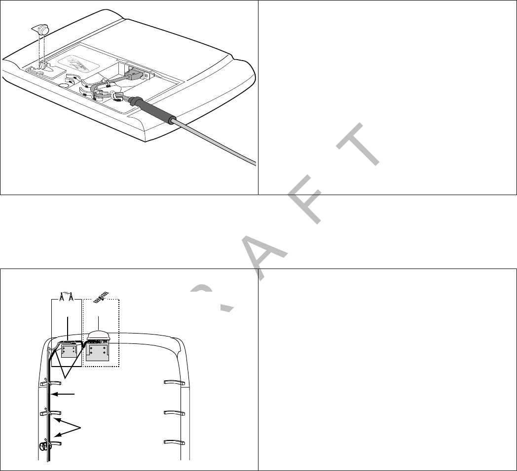
Inspecting the Wireless Interface Box 200 (WIB200) and the Optional Satellite Data Modem (SDM) Preventive
Maintenance Inspection
E-6 MAY CONTAIN U.S. AND INTERNATIONAL EXPORT CONTROLLED INFORMATION 80-J9968-1 Rev. A
DO NOT COPY
Inspecting the Wireless Interface Box 200 (WIB200) and the Optional Satellite Data
Modem (SDM)
6. Inspect the underside of the DIU200 to make
sure the tie wraps are securely tightened and
the cable is not damaged.
The illustration to the left is the underside of
the DIU200 showing the tie wraps.
1. Make sure all cables are protected with
convoluted tubing and are in good condition.
Make sure cables have no kinks or bends and
are not being pulled tightly against metal
edges that can rub or cut the cables.
2. Make sure there are adequate service (drip)
loops in the cables at the antenna and where
they enter the vehicle.
05AAA_233
Cable Routing
Tie Wraps
Rear View
Cable tied to existing
boomerang brackets
Convoluted tubing
Drip loops
05AAA_223DQMCP
Satellite
Data Modem
Terrestrial
Antenna
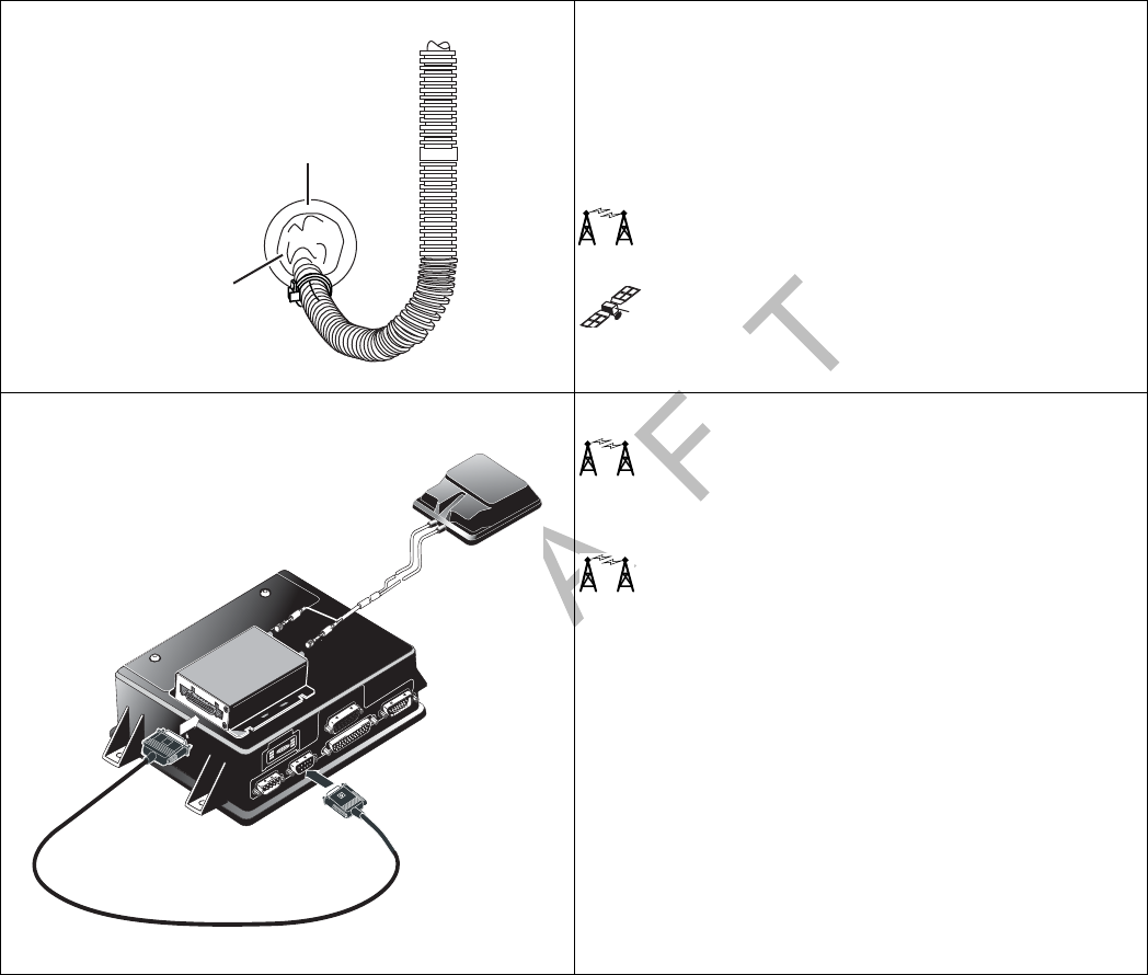
80-J9968-1 Rev. A MAY CONTAIN U.S. AND INTERNATIONAL EXPORT CONTROLLED INFORMATION E-7
Preventive Maintenance Inspection Inspecting the Wireless Interface Box 200 (WIB200) and the Optional Satellite Data
Modem (SDM)
DO N OT
COPY
3. Make sure grommets are in place around any
holes the cables pass through.
Make sure RTV sealant or refrigeration/tar
tape is intact and provides a good seal on any
holes that lead to the exterior of the vehicle.
Go to step 4. if you are inspecting a terrestrial
unit.
Go to step 6. if you are inspecting a satellite
unit.
4. Make sure the antenna is securely attached to
the mount. Check the mount hardware to
make sure it is secure and does not show any
signs of loosening.
5. Check that the antenna cable connectors
have not worked themselves loose from the
MAS200.
Grommet
Refrigeration/
Tar Tape or
RTV Sealant
05AAA_043_T
IUIU
DSPLDSPL MDMMDM PWRPWR
I / 0I / 0
USB / SERUSB / SER
MAS
TDM
TDM Cable
I/0I/0
Terrestrial
Antenna
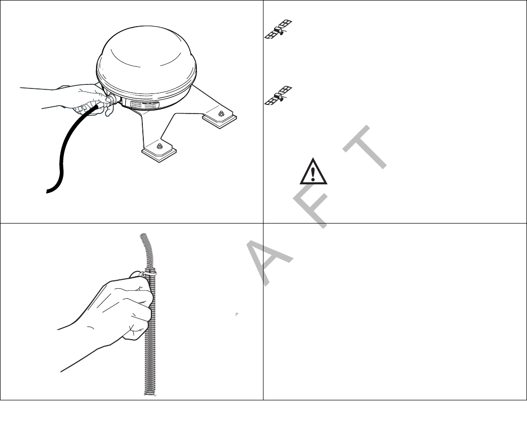
Inspecting the Wireless Interface Box 200 (WIB200) and the Optional Satellite Data Modem (SDM) Preventive
Maintenance Inspection
E-8 MAY CONTAIN U.S. AND INTERNATIONAL EXPORT CONTROLLED INFORMATION 80-J9968-1 Rev. A
DO NOT COPY
6. Make sure the SDM is securely attached to
the SDM mount. Check the mount hardware to
make sure it is secure and does not show any
signs of loosening.
7. Twist SDM to verify that the SDM connector is
hand-tightened and secure. The SDM
mounting bolts should be tightened to the
recommended torque of 72 inch/pounds (not
foot/pounds).
Caution
Do not use refrigeration/tar tape or RTV
sealant on the SDM connector.
Go to step 8. to complete the SDM inspection.
8. Visually inspect all tie wraps to make sure they
are not brittle and do not break. If a tie wrap is
damaged or brittle, replace it.
06AAA_127
Twist tie wrap
between fingers
to make sure it
doesn't break.
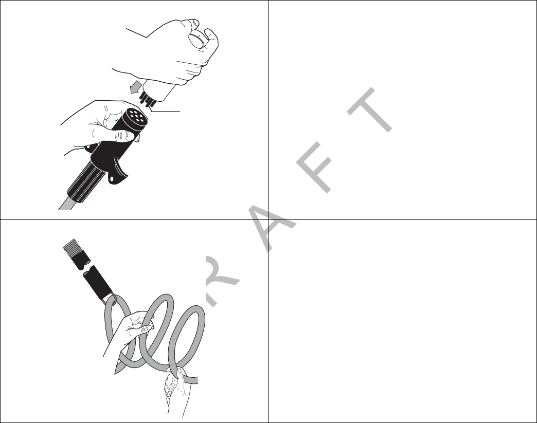
80-J9968-1 Rev. A MAY CONTAIN U.S. AND INTERNATIONAL EXPORT CONTROLLED INFORMATION E-9
Preventive Maintenance Inspection Verifying TrailerTRACS® System Connections
DO N OT
COPY
Verifying TrailerTRACS® System Connections
1. Make sure all 7-way connection points have
been cleaned, inspected, and greased.
Qualcomm recommends that you use
dielectric grease on the connection points.
2. Check the 7-way coil cord for nicks, cuts, or
abrasions. Replace the cord as necessary.
Brushes
04AAA 161
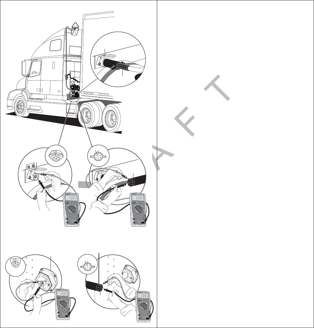
Verifying TrailerTRACS® System Connections Preventive Maintenance Inspection
E-10 MAY CONTAIN U.S. AND INTERNATIONAL EXPORT CONTROLLED INFORMATION 80-J9968-1 Rev. A
DO NOT COPY
3. Make sure there is voltage (12–24V) on pin 7
at all 7-way connection points (on the tractor
and trailer).
Make sure you connect to ground (pin 1) as
well when performing this step.
The illustrations at left show the connection at
the tractor and at the trailer.
Receptacle
Remove Plug
7- Way
Receptacle
1
7
FLUKE
77 III77 III
MULTIMETER
AUTO
0
010
20
30
RANGE
OFF
V
mV
A
A
HOLD
FLUKE
77 III77 III
MULTIMETER
AUTO
0
010
20
30
RANGE
OFF
V
mV
A
A
300300
mA
10 A
COM
V
HOLD
300300
mA
10 A
COM
V
7-Way
Plug
1
7
04AAA_158T
7- Way Receptacle
at the Trailer nose
7- Way plug
at the Trailer end
7
FLUKE
77 III
77 III
MULTIMETER
AUTO
0
010
20
30
RANGE
OFF
V
mV
A
A
HOLD
FLUKE
77 III
77 III
MULTIMETER
AUTO
0
010
20
30
RANGE
OFF
V
mV
A
A
300
300
mA
10 A
COM
V
HOLD
300
300
mA
10 A
COM
V
7-Way
Plug
1
71
04AAA_159
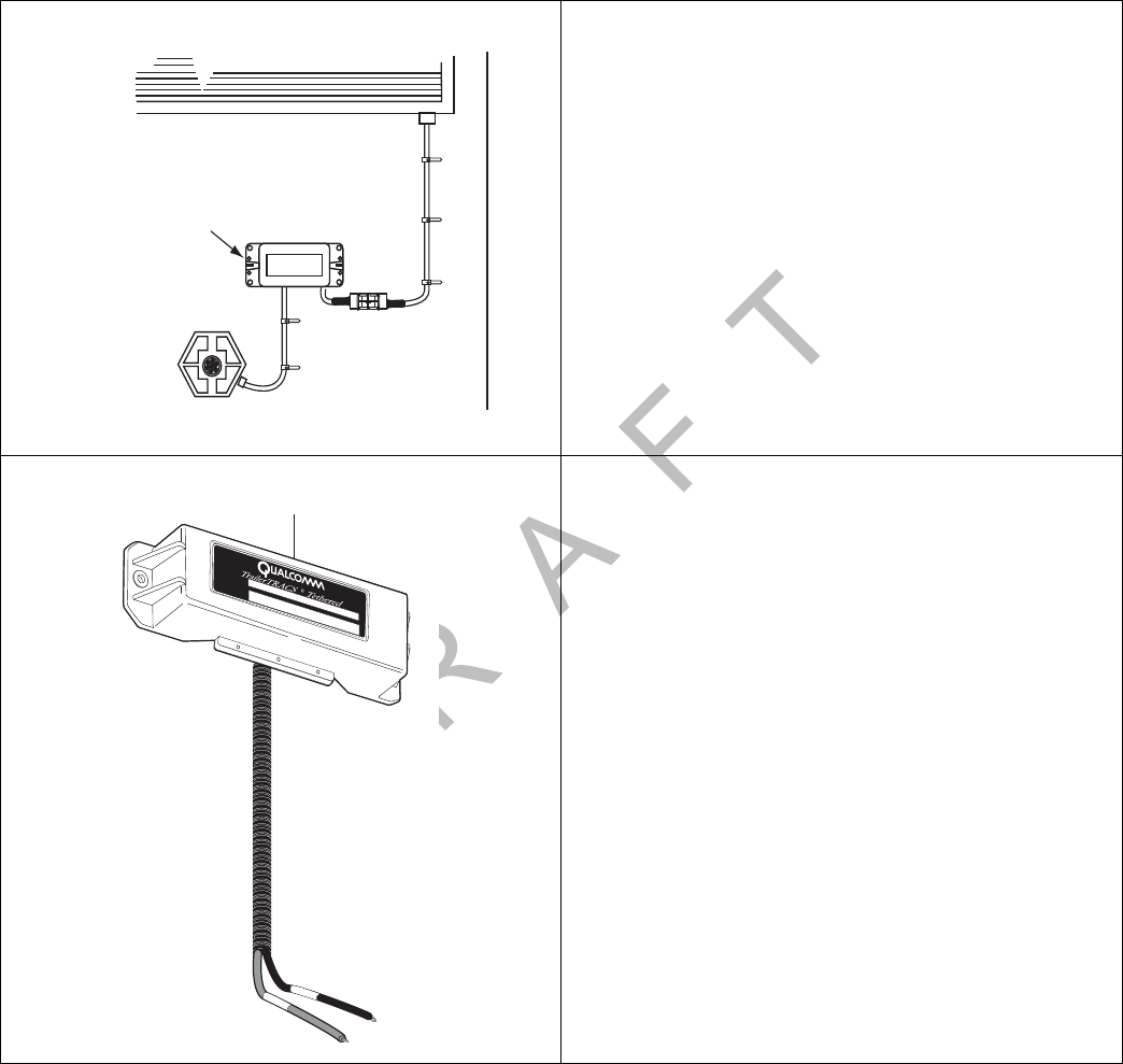
80-J9968-1 Rev. A MAY CONTAIN U.S. AND INTERNATIONAL EXPORT CONTROLLED INFORMATION E-11
Preventive Maintenance Inspection Verifying TrailerTRACS® System Connections
DO N OT
COPY
4. Connect a test transmitter to the truck.
5. Turn IGN to ON.
6. Access the TrailerTRACS ID screen by
selecting the Trailer icon and verifying that the
transmitter’s ID displays.
7. For refrigeration customers, do the
following:
• Inspect both ends of the refrigeration cable
for corrosion and clean if necessary.
• Turn IGN to ON.
Verify the refrigeration connection and data
transfer by accessing the Refrigeration
Status screen.
• With the refrigeration switch in the ON
position, verify the REFRIGERATOR
STAT# field is incrementing approximately
once a minute. The manufacturer code for
the unit should appear at the end of the
refrigerator status number: “T” for Thermo
King, or “C” for Carrier.
TrailerTRACS
Transmitter
Test with Known,
Good TTRACS
Transmitter
OM_E-0093-210goodxmtter.eps
PART NO.
SER NO.
TrailerTRACS Transmitter

Verifying TrailerTRACS® System Connections Preventive Maintenance Inspection
E-12 MAY CONTAIN U.S. AND INTERNATIONAL EXPORT CONTROLLED INFORMATION 80-J9968-1 Rev. A
DO NOT COPY

80-J9968-1 Rev. A MAY CONTAIN U.S. AND INTERNATIONAL EXPORT CONTROLLED INFORMATION F-1
DO NOT COPY
F
Component and Document Information
Topics in this appendix provide document control numbers (DCNs) and material control
numbers (MCNs) for the different documents and Qualcomm® MCP200 components referred
to in this guide.
MCP200 System Component MCNs Referenced in this Guide. . . . . . . . . . . . . . . . F-2
MCNs for Sealants and Lubricants Referenced in this Guide . . . . . . . . . . . . . . . . . F-6
MCN for Qualcomm-recommended Torque Wrench Referenced in this Guide. . . . F-6
For technical questions, contact Qualcomm Enterprise Services (QESSM) Customer Support.
Customer Support is staffed 24 hours a day, 365 days a year:
In the United States, call 800-541-7490
In Canada, call 800-863-9191
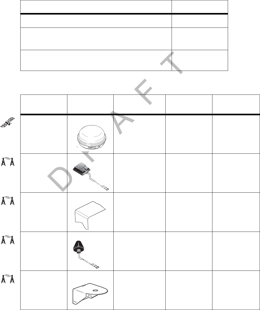
DCNs for Documents Referenced in this Guide Component and Document Information
F-2 MAY CONTAIN U.S. AND INTERNATIONAL EXPORT CONTROLLED INFORMATION 80-J9968-1 Rev. A
DO NOT COPY
DCNs for Documents Referenced in this Guide
MCP200 System Component MCNs Referenced in this Guide
Document Name DCN
Outdoor Unit Mount Installation Guide TL80-6270-1
Qualcomm® MCP 200 Series and Accessory Diagnostic
Guide
80-J9969-1
How to Use the Wireless Panic Button Remote
Transmitter (Visor Card) 80-J6060-1
System
component Illustration Latest MCN
Alternate
MCNs Notes
Satellite data
modem (SDM) 10-J8278 10-J9490
(SDM2)
Flat antenna CV90-J9496-20
Vertical
antenna mount
for flat antenna
10-J9485-1
Cone antenna CV90-J1045-20
Vertical
antenna mount
for cone
antenna
65-J2056-1
07AAA 57D
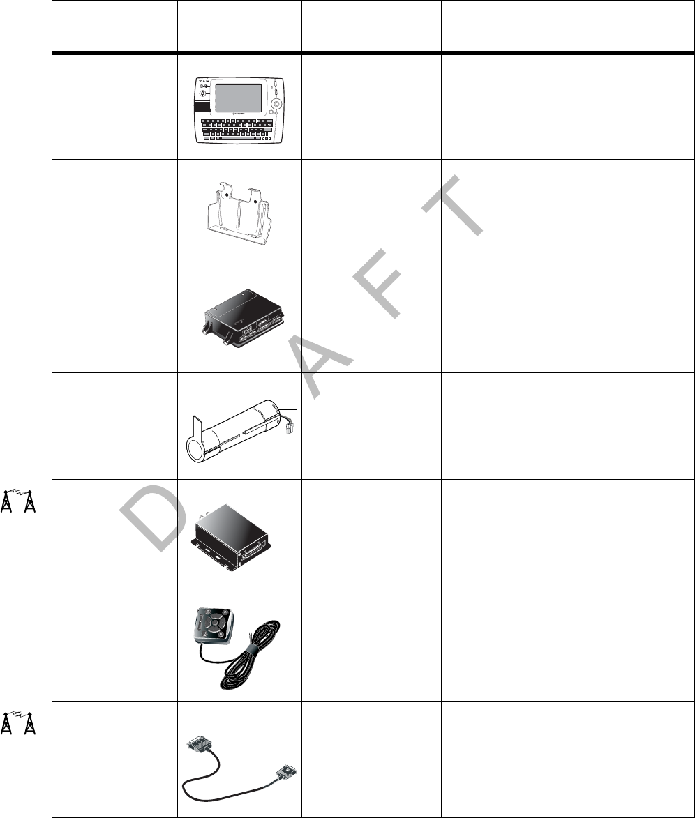
80-J9968-1 Rev. A MAY CONTAIN U.S. AND INTERNATIONAL EXPORT CONTROLLED INFORMATION F-3
Component and Document Information MCP200 System Component MCNs Referenced in this Guide
DO N OT
COPY
Media display
unit (MDU) CV90-J4820-1
Media display
unit (MDU)
holster
10-J8407-1
Mobile
application
server (MAS)
10-J9313-8
Backup battery CV90-J4341-2
Terrestrial data
modem CA90-J9400-x
Remote control
device (RCD) CV90-J8640
Terrestrial data
modem cable CV90-J9264-2
System
component Illustration Latest MCN
Alternate
MCNs Notes
Esc
1
!
2
@
3
#
4
$
5
%
6
^
7
&
8
*
9
(
0
)
=
Backspace
+
Tab
Q
Caps
0WE RT Y UI P
{
[
{
[
Enter
Shift
Ctrl Alt Sym
Delete
Shift
LKJHGFDSA "
'
MN
BVC
X
Z
V
V
?
!
Opt
Back
05AAA_215
05AAA 220A
05AAA_043
IU
IU
DSPL
DSPL
MDM
MDM
PWR
PWR
I / 0
I / 0
USB / SER
USB / SER
Weight 3.25 lbs.
(including battery)
07AAA_57A
05AAA_219
D
I/0
I/0
07AAA_56A
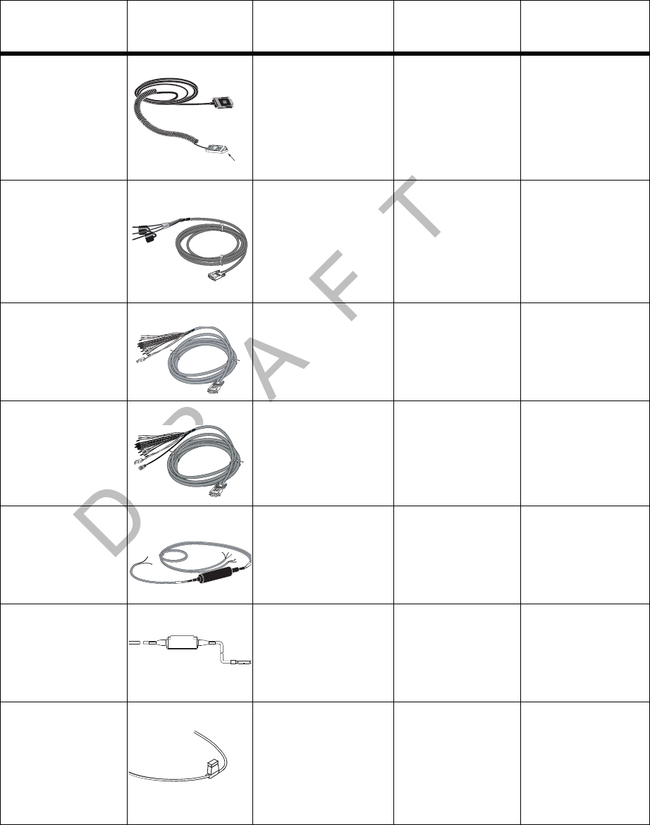
MCP200 System Component MCNs Referenced in this Guide Component and Document Information
F-4 MAY CONTAIN U.S. AND INTERNATIONAL EXPORT CONTROLLED INFORMATION 80-J9968-1 Rev. A
DO NOT COPY
Media display
unit (MDU)
cable
CV90-J4880-17
Power cable CV90-J4877-20
Accessory
cable
(standard)
CV90-J9284-20 This cable is the
standard cable.
Accessory
cable (full
function)
CV90-J8773-20 This cable is the
full function
cable.
Speaker switch
cable CV90-J4843-8
CAN converter
cable CV90-J4843-8
5 amp fuse (for
TrailerTRACS®)
65-53011-1
System
component Illustration Latest MCN
Alternate
MCNs Notes
05AAA 042
Protective Cap
05AAA_041A
Q
05AAA 038T
05AAA_038
CAN BUSCAN BUSCAN BUS
Blue
(TTRACS)
5 Amp Fuse
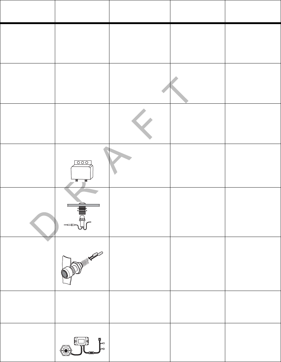
80-J9968-1 Rev. A MAY CONTAIN U.S. AND INTERNATIONAL EXPORT CONTROLLED INFORMATION F-5
Component and Document Information MCP200 System Component MCNs Referenced in this Guide
DO N OT
COPY
Reefer cable
assembly with
6-pin Deutsch
connector
N/A 45-J7857-6 For use with
Thermo King
refrigeration
trailers
Reefer Cable
Packard cable
assembly with
3-pin connector
N/A 45-J7856-6 For use with
Carrier
refrigeration
trailers
Reefer cable
assembly with
5-pin Deutsch
connector
N/A 45-J7854-6 For use with
Carrier
refrigeration
trailers
Message
waiting buzzer 65-3922-1
Remote
message
waiting light
CV90-6414-1
Panic button
and cable CV90-J1377-5
Kit, Wireless
Panic Spare
XMTR Upgrade
N/A 65-J6070-1
TrailerTRACS
system for
reefer
10-53481-2 10-52525-6
System
component Illustration Latest MCN
Alternate
MCNs Notes
12V
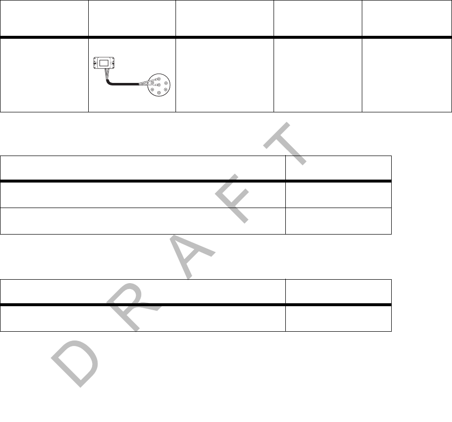
MCNs for Sealants and Lubricants Referenced in this Guide Component and Document Information
F-6 MAY CONTAIN U.S. AND INTERNATIONAL EXPORT CONTROLLED INFORMATION 80-J9968-1 Rev. A
DO NOT COPY
MCNs for Sealants and Lubricants Referenced in this Guide
MCN for Qualcomm-recommended Torque Wrench Referenced in this Guide
TrailerTRACS
system for dry
van
10-53481-1 10-52525-4
Sealant MCN
Sealant, Mastic Butyl Rubber .125" x 2" x 12" Black 755-12528-0003
Seal, Coax Plastic 1/2" x 3/32" x 10" Strips OEM Pkg 755-01910-0001
Tool MCN
Torque wrench for replacing the radome 800-01730-0017
System
component Illustration Latest MCN
Alternate
MCNs Notes
Pin7
(AUX)
Pin 1
(GND)
01AAJ_81B

80-J9968-1 Rev. A MAY CONTAIN U.S. AND INTERNATIONAL EXPORT CONTROLLED INFORMATION G-1
DO NOT COPY
G
Feedback Form
Your comments are important to us as we evaluate the best way to provide you with quality
documentation. Thank you for taking the time to complete this survey.
After completing this form, please fax a copy to: QESSM Information Design and Training
(858) 845-6478.
Feedback Form
Company Information
Please provide this information or attach your business card.
Company:
Your Name:
Your title:
Phone:
Your primary job: (check one)
mechanic ❏
shop foreman ❏
service writer ❏
How often do you use a Qualcomm® manual?
❏ Daily ❏ Weekly ❏ Monthly
❏ Never ❏ Only when I have questions
If you don’t use a Qualcomm manual on a regular basis, please indicate the reason: (check
all that apply)
❏ Prefer calling customer service
❏ Too busy to look in manual
❏ Don’t have a copy
❏ Other __________________________________________________________________
If you haven’t used a Qualcomm manual, stop here and return the survey.

Documentation Content Feedback Form
G-2 MAY CONTAIN U.S. AND INTERNATIONAL EXPORT CONTROLLED INFORMATION 80-J9968-1 Rev. A
DO NOT COPY
Documentation Content
1. Please indicate your opinion of the information included in the Qualcomm® MCP 200
Series and Accessory Installation Guide:
❏ Too detailed
❏ Right amount of information
❏ Not detailed enough
2. How often do you find what you’re looking for in the manual?
❏ Always
❏ Frequently
❏ Sometimes
❏ Rarely
❏ Never
3. What is the reason you cannot find information in the manual?
❏ Information was omitted
❏ Not in the Table of Contents
❏ Not in the Index
❏ Manual is poorly organized
❏ Other ______________________________________________________________
4. Please rate your level of satisfaction with the following areas in the manual:
(5=Very satisfied 4=Satisfied 3=Neither Satisfied nor Dissatisfied
2=Dissatisfied 1=Very Dissatisfied)
Diagnostic Procedures 5 4 3 2 1
Flowchart Information 5 4 3 2 1
Graphics/pictures 5 4 3 2 1
5. Please rate your level of satisfaction in how the manual assists your company in each of
the following areas:
(5=very satisfied 4=Satisfied 3=Neither Satisfied nor Dissatisfied
2=Dissatisfied 1=Very Dissatisfied)
Training for new staff 5 4 3 2 1
Step-by-step procedures 5 4 3 2 1
As a reference manual 5 4 3 2 1
Overall usefulness 5 4 3 2 1
6. Is the writing style in the manual easy to understand:
❏ Yes
❏ No
Documentation Format
1. Please indicate how you like the size of the manual:
❏ Manual is too small

80-J9968-1 Rev. A MAY CONTAIN U.S. AND INTERNATIONAL EXPORT CONTROLLED INFORMATION G-3
Feedback Form Documentation Format
DO N OT
COPY
❏ Manual is OK as it is
❏ Manual is too large
2. Please rate your level of agreement with the layout of pages in the manual:
(5=Very satisfied 4=Satisfied 3=Neither Satisfied nor Dissatisfied
2=Dissatisfied 1=Very Dissatisfied)
Pages are uncluttered 5 4 3 2 1
Steps are easily identified5 4 3 2 1
Print is easy to read 5 4 3 2 1
3. Would documentation from Qualcomm be more useful to you if it were delivered on-
line?
❏ Yes
❏ No
4. How important is it for you to receive a paper copy of the documentation from
Qualcomm?
❏ Very important
❏ Important
❏ Not important
5. What would be the best way for you to learn about the Qualcomm mobile computing
platform?
❏ Product training manual
❏ Computer-based training
❏ Video tape
❏ Other ______________________________________________________________
6. What do you like best about our manuals?
_____________________________________________________________________
_____________________________________________________________________
7. If there is one thing you could change about our manuals, what would it be?
_____________________________________________________________________
_____________________________________________________________________
8. Other comments:
_____________________________________________________________________
_____________________________________________________________________
We may want to contact you to ask some additional questions about the documentation from
Qualcomm. Would you be willing to talk to a Qualcomm representative about these manuals?
❏ Yes, the best time to reach me is ___________
❏ No
Thank you! Your comments are appreciated.

Documentation Format Feedback Form
G-4 MAY CONTAIN U.S. AND INTERNATIONAL EXPORT CONTROLLED INFORMATION 80-J9968-1 Rev. A
DO NOT COPY

80-J9968-1 Rev. A MAY CONTAIN U.S. AND INTERNATIONAL EXPORT CONTROLLED INFORMATION Glossary-1
DO NOT COPY
Glossary
44-Pin I/O Accessory Cable. See Full Function Accessory Cable and Standard Accessory
Cable.
Bad MCP Status. When an MCP fault has been detected, the Status field will display 10000/
10001, 12000/12001, 13000/13001, or 22000/22001. See specific Status numbers, or
Qualcomm® MCP and Accessory Diagnostic Guide for details on status codes.
Black Box. See Mobile Application Server.
Buzzer. An indicator typically mounted behind the dash that buzzes if a message has been
received. See Message Waiting Light, Remote Message Waiting Light.
Calibration. Calibration is performed when the MCP cannot use the J1708/1587 data link for
SensorTRACS® input. After sensor calibrations have been determined, the dispatch
computer operator needs to send the calibration numbers to the MCP. See RPM Calibration
and Speed/Distance Calibration.
CDU. See Compact Display Unit.
C/No Value. Indicates the strength of the data satellite signal being received from or sent to
the satellite. FL C/No indicates the forward signal strength; RL C/No indicates the return
signal strength.
Compact Display Unit (CDU). The user interface device that can be used to display the
Qualcomm-provided navigation application for the Qualcomm MCP system.
Configuration Screen. This screen shows how the MCP is configured. The System icon
(satellite dish) takes you to this screen; then press the Config tab.
Data Satellite. This satellite handles all message traffic between the vehicle and the NMC. It
uses Ku-band signals and is located approximately 22,300 miles over the equator at 83° west
longitude (south of Georgia).
Display Cable. The display cable connects the media display unit (MDU) to the mobile
application server (MAS).
FL C/No Value. Measures the energy going from the satellite to the mobile application server
(MAS).

Glossary
Glossary-2 MAY CONTAIN U.S. AND INTERNATIONAL EXPORT CONTROLLED INFORMATION 80-J9968-1 Rev. A
DO NOT COPY
Full Function Accessory Cable. Connects the mobile computing platform (MCP) to the
J1708/1587 data link, as well as other vehicle inputs and optional system devices. This cable
provides the necessary wiring for all optional system features such as display screen
disabling, SensorTRACS system, TrailerTRACS® system, panic button, TTS, RCD, Printer,
Scanner, CDU, Axle, RPM, and PTOP/PTOC. See Appendix A for details on pinouts.
Global Positioning System (GPS). Provides current vehicle positioning with latitude and
longitude updates displayed on the MCP.
GPS. See Global Positioning System.
GPS Screen. The display unit screen shows the status of the mobile computing platform
(MCP) satellite positioning. The System icon (satellite dish) takes you to this screen; then
press the GPS tab.
Holster. The container that holds the MDU when it is not in use.
Installation Planning Worksheet. A worksheet on which you can plan your installations.
Installer Screen. MCP screen that displays information you will need to check the
SensorTRACS parameters. This screen can be accessed in the SensorTRACS application at
the Installer tab.
J1708/1587 Network. The MCP is able to monitor critical vehicle data from this low speed, bi-
directional data bus. The data posted to this bus are provided by a single electronic control
unit (ECU). See J1939 Network and Traditional Sensors Network.
J1708 Enabled. “J1708 enabled” means that the MCP has been set up to look at J1708 data
via the J1708/1587 data link. The dispatch computer operator must send a message to the
MCP that “tells” it to understand input from the J1708/1587 bus and define driving thresholds.
J1939 Network. The MCP is able to monitor critical vehicle data from this high speed data
bus. The data posted to this bus are provided by multiple electronic control units (ECUs). SAE
J1939 message protocol and controller area network (CAN) bus represent the prevalent on-
vehicle networking for most construction equipment manufacturers. See J1708/1587 Network
and Traditional Sensors Network.
J1939 Enabled. “J1939 enabled” means that the MCP has been set up to look at J1939 data
via the J1939 data link. The dispatch computer operator must send a message to the MCP
that “tells” it to understand input from the J1939 bus and define driving thresholds.
Line-of-Sight Requirement. The satellite data modem (SDM) requires an unobstructed line-
of-sight view to the satellite in order to clearly send and receive signals. The SDM must be
able to send and receive the signals at a 12° angle above the horizontal plane of the unit.
There must be an unobstructed view of the satellite (southern sky) at all angles above 12°.
MAS. See Mobile Application Server.
Material Control Number (MCN). The Qualcomm part number.
MCN. See Material Control Number.

80-J9968-1 Rev. A MAY CONTAIN U.S. AND INTERNATIONAL EXPORT CONTROLLED INFORMATION Glossary-3
Glossary
DO N OT
COPY
MCP. See Mobile Computing Platform.
MCP Serial Number (Unit Address). Located on the connector plate of the mobile
application server (MAS). The MCP System screen also has this information.
MDU. See Media Display Unit.
Media Display Unit (MDU). The standard display unit for the Qualcomm MCP. It consists of
a keyboard and color TFT LCD display.
Message Waiting Light. An indicator light on the display that illuminates if a message has
been received.
Mobile Application Server (MAS). The mobile application server contains the operating
circuitry and memory for the MCP system. The unit does not require operator access. It is
always installed on a mounting tray. The MAS is commonly referred to as the black box.
Mobile Computing Platform (MCP). A two-way, mobile communication system that allows
dispatchers and drivers to send and receive text messages, and also provides vehicle
location and performance data.The MCP is mounted in the vehicle and consists of the
following components:
• Mobile application server (MAS)
• Display unit and its holster
• Terrestrial data modem (TDM) and Terrestrial Antenna or Satellite Data Modem (SDM)
• Cables
Network Management Computer (NMC). Computer at the Network Management Facility
that receives and handles the message traffic between the dispatch center and the fleet.
Network Operations Center (NOC). This facility is responsible for processing and managing
the message traffic between the dispatch center and the fleet. Within the NOC is the Network
Management Computer (NMC), which actually receives and handles the message traffic. In
the continental United States, the NOC is located at QUALCOMM, Inc., in San Diego, CA.
NMC. See Network Management Computer.
NOC. See Network Operations Center.
NO SIGNAL Light. An indicator light on the display that comes on if the mobile computing
platform (MCP) has lost contact with the data satellite and is searching for the satellite signal.
Odometer Screen. The mobile computing platform (MCP) display unit screen that displays
the life-to-date (LTD) value and sensor calibration information. This screen can be accessed
in the SensorTRACS application at the Odometer tab.

Glossary
Glossary-4 MAY CONTAIN U.S. AND INTERNATIONAL EXPORT CONTROLLED INFORMATION 80-J9968-1 Rev. A
DO NOT COPY
Optional Accessories. Any of these may be installed for the MCP:
• Compact Display Unit (CDU)
• Panic button
• Printer (product of O’Neil Product Development, Inc.)
• Remote message waiting light
• Remote message buzzer
• Scanner (product of BCS Solutions)
• Vehicle information systems (SensorTRACS system and TrailerTRACS system)
OVT/CDMA Screens. These screens show the strength of the wireless communication
network signal being received. The System icon (satellite dish) takes you to these screens;
then press the OVT/CDMA tab.
Panic Button. Allows the driver to notify the Qualcomm Network Management Computer and
the company dispatcher when an emergency situation exists.
Positioning System. See Global Positioning System.
Power Cable. Connects the vehicle 12/24 volt power source and system ground to the
mobile application server.
Printer. Provides the driver with a hard copy of the MCP forward or return message screen
display.
Qualcomm Dispatch Software (QTRACS® system). The software on the trucking
company’s dispatcher computer. This is the dispatcher’s interface with the Qualcomm MCP. It
allows the dispatcher to send and receive messages, request MCP location information, and
perform other dispatcher functions. The dispatch computer communicates with the NMC via a
modem over a commercial or leased telephone line.
Qualcomm Enterprise Services (QESSM) Customer Support. Call 24-hour Customer
Support for information and additional help at any time, including holidays. In the United
States, call 800-541-7490; in Canada, call 800-863-9191.
RCD. See Remote Control Device.
Received Signal Strength Indication (RSSI). The strength of the wireless communication
network signal being received by the antenna during forward link acquisition to the wireless
network provider. The RSSI should be less than 110.
Remote Control Device (RCD). A small device that mounts on the dash of the vehicle. It
allows the driver to listen to messages while driving and also to navigate through applications.
Return Material Authorization (RMA). An order used to authorize, schedule, and track the
return, repair or replacement, and shipment of equipment.
RL C/No Value. Measures the energy from the mobile application server (MAS) to the
satellite.

80-J9968-1 Rev. A MAY CONTAIN U.S. AND INTERNATIONAL EXPORT CONTROLLED INFORMATION Glossary-5
Glossary
DO N OT
COPY
RPM Calibration. Used to determine the engine RPM when RPM data comes from the RPM
sensor instead of the J1708/1587 data link.
RSSI. See Received Signal Strength Indication.
Satellite Data Modem (SDM). The SDM contains the antenna that sends and receives
satellite signals. The unit is usually installed as high as possible on the vehicle so that the
antenna has a clear view of the satellite.
Satellite Data Modem Cable. The SDM cable connects the SDM to the mobile application
server.
Scanner. Provides drivers a way to send documents to their home office for back office
processing without having to leave their truck.
SD Card. See Secure Digital Card.
SDM. See Satellite Data Modem.
SDM Screens. These two screens show the various attributes of satellite signal strength.
The System icon (satellite dish) takes you to these screens; then press the SDM tab.
Secure Digital (SD) Card. A small card that fits into a slot in the mobile application server
and allows the driver to upgrade the Qualcomm MCP over-the-air and load applications.
SensorTRACS System. An accessory of the Qualcomm MCP that allows companies to
collect vehicle trip and performance data.
Software Version. See MCP System Screen.
Speed/Distance Calibration. Used to determine the road speed and/or distance when the
speed or distance data comes from the speed sensor instead of the J1708/1587 data link.
Standard Accessory Cable. Connects the mobile computing platform (MCP) to the J1708/
1587 data link, as well as other vehicle inputs and optional system devices. This cable
provides the necessary wiring for optional system features such as display screen disabling,
SensorTRACS system, TrailerTRACS system, panic button, TTS, RCD, Printer, and
Scanner. It does not support wiring for the CDU, Axle, RPM, PTOP, or PTOC. See Appendix
A for details on pinouts.
Status 10000/10001. Occurs when the terrestrial data modem (TDM) is not communicating
with the mobile application server (MAS).
Status 12000/12001. Occurs when the backup battery needs to be replaced.
Status 13000/13001. Occurs when there is an internal mobile application server (MAS)
problem.
Status 22000/22001. Occurs when there are problems with positioning.
System Parameters Screen. The screen that displays information you will need to verify the
speed and RPM calibrations.

Glossary
Glossary-6 MAY CONTAIN U.S. AND INTERNATIONAL EXPORT CONTROLLED INFORMATION 80-J9968-1 Rev. A
DO NOT COPY
System Screen. The Firmware Version screen displays the different software versions (and
hardware versions) installed in the MCP. The System icon (satellite dish) takes you to this
screen; then press the System tab.
System Verification. A functional system check that should be performed after installation
and periodically to verify that the MCP is operating properly.
TDM. See Terrestrial Data Modem.
Terrestrial Antenna. Communicates with the PCS receiver for data transmission and the
GPS receiver for positioning information.
Terrestrial Data Modem (TDM). This is the wireless modem that connects the antenna to the
MAS.
Terrestrial Data Modem Cable. The TDM cable connects the TDM to the mobile application
server.
Text-to-Speech (TTS). A feature of the Qualcomm MCP that converts text messages or
alerts to spoken words which are then played through an audio speaker.
Total Distance. The accumulated distance traveled by a vehicle during its operation. The
MCP collects distance data in one of three ways:
• Modern electronic truck engines provide distance data via the engine controller module
(ECM).
• In some older electronic engines, total distance is not available through the ECM and the
MCP uses input from the speed sensor and the available J1708/1587 data to calculate
distance.
• In non-electronic trucks, the speed sensor provides both speed and distance data.
Traditional Sensors Network. The MCP monitors speed directly via the speed transducer
on the transmission and RPM via the transmission fly wheel. See J1708/1587 Network and
J1939 Network.
Traditional Sensors Enabled. “Traditional sensors enabled” means that the MCP has been
set up to look at traditional sensors via the traditional sensors data link. The dispatch
computer operator must send a message to the MCP that “tells” it to understand input from
the traditional sensors and define speed and RPM.
TrailerTRACS System. An optional Qualcomm MCP feature that allows dispatch to monitor
trailer connects and disconnects. The TrailerTRACS system can also monitor the refrigeration
unit of the trailer.
TTS. See Text-to-Speech.
Unit Address. See MCP Serial Number (Unit Address).
Vehicle Information Systems (VIS). See SensorTRACS system and TrailerTRACS System.

80-J9968-1 Rev. AMAY CONTAIN U.S. AND INTERNATIONAL EXPORT CONTROLLED INFORMATION Index-1
Index
A
ABS
interoperability 15-3
PLC signal filtering 15-3
Acceptable sealants 4-11
B
Buzzer installation
guidelines 17-2
mounting location 17-2
verification 17-2
C
Cable installation
accessory cable 5-7–??
antenna cable 7-4
display cable 9-4
grounding guidelines 5-7
power cable 5-5–5-6
routing and protecting cables
3-11–3-13
satellite data modem cable 8-5–8-7
speaker switch cable 10-4–10-6
understanding cable basics 3-11
CDMA. See Code Division Multiple
Access
Code Division Multiple Access (CDMA)
How it’s used with the Qualcomm
MCP 1-4
Wireless network description 1-4
D
Data source installation
J1708/1587 data source wire
installation 11-10
J1939 CAN0 wire connection
11-8–11-9
J1939 CAN1 wire connection
11-5–11-7
J1939 data source installation
11-3–11-9
Data source verification
11-11–11-12
Diagnostic flowcharts
basic MCP system verification
12-11–12-12
Display unit installation
connecting the display cable
9-4–9-5
inserting the MDU into holster 9-5
inspecting the display cable 9-4
installing the holster using well-nut
fasteners 9-3
selecting a location 9-2–9-3
Display Unit Screens
CER screen 12-8
config screen 12-7
engineering screen 12-8
GPS screen 12-6
OVT screens 12-4–12-5
SDM screens 12-5
system screen 12-3–12-4
VDS (status) screen 12-9
F
Forms
Basic MCP System Verification
12-18
MCP installation planning
worksheets 4-8
Permanent Fleet Size Reduction
Request Form C-7
Index-2 MAY CONTAIN U.S. AND INTERNATIONAL EXPORT CONTROLLED INFORMATION 80-J9968-1
G
Global positioning system (GPS)
how the Qualcomm MCP uses GPS
1-5
I
Inspections
antenna and TDM E-6–E-8
MAS E-2–E-3
MDU E-4–E-6
M
Mobile application server (MAS)
installation
connecting cables 5-9, 8-7, 9-6
selecting a mounting location
5-3–5-4
Mobile computing platform (MCP)
acceptable sealants 4-11
definition 1-6
installation guidelines 4-2
installation planning 4-2
installation planning worksheets 4-8
tools and supplies 4-11
typical installation locations 4-3–4-7
typical installation sequence
4-2–4-3
P
Panic button
installation 19-2–19-3
verification 19-4
PCS. See Personal Communications
Service
Personal Communications Service
(PCS)
How it’s used with the Qualcomm
MCP 1-4
System description 1-4
Printer
basic installation procedure 20-3
installation guidelines
location 20-2
mounting bracket 20-2
printer data cable 20-2
printer power cable 20-2
verification 20-4
wiring configuration 20-2
PTO
overview 13-12–13-14
verification 13-14
Q
Qualcomm MCP
components 1-3–1-4
Qualcomm MCP components
backup battery 2-6
media display unit (MDU) 2-4
mobile application server (MAS) 2-5
optional accessories 2-7
remote control device (RCD) 2-7
satellite data modem (SDM) 2-3
terrestrial data modem (TDM) 1-6,
2-3
R
Recommended tools and supplies
MCP installation 4-11
Remote control device (RCD)
connecting speakers 10-4–10-6
installation 10-2–10-3
selecting a location 10-2
speaker requirements 10-3
Remote message waiting light (RMWL)
installation 18-2
installation verification 18-2
Return Material Authorization (RMA)
customer damaged equipment C-6
missing, lost, stolen, or destroyed
equipment C-6
obtaining an RMA number C-2
Permanent Fleet Size Reduction
Request Form C-7
policies C-4
process C-1
returning equipment C-5
what you can return C-4
RMWL. See Remote message waiting
light
S
Safety information
80-J9968-1 Rev. AMAY CONTAIN U.S. AND INTERNATIONAL EXPORT CONTROLLED INFORMATION Index-3
definitions i-xi
selecting a location for a display unit
i-xi
Satellite data modem (SDM) installation
connecting the SDM cables 8-5–8-6
general installation guidelines 8-2
installing mounting bolts 8-3
line-of-sight requirements 8-4
orienting the SDM on the mount 8-2
trailer swing area 8-5
Scanner
basic installation procedure 21-1,
21-3
calibrating 21-3
cleaning 21-5
installation guidelines
location 21-2
mounting 21-2–21-3
printer power cable 21-2
sending a scan 21-4
SensorTRACS installation
SensorTRACS display screens
13-3–13-11
special alert display messages
13-12
system overview 13-2
verification 13-2–13-3
System verification, Basic MCP
flowchart 12-11–12-12
form 12-18
procedure 12-13–12-18
T
Terrestrial antenna mount installation
using VHB tape 7-2–7-3
Terrestrial data modem (TDM)
installation
connecting cables 7-4
Tools and supplies
MCP installation 4-11
TrailerTRACS® system
ABS interoperability 15-3
ABS PLC signal filtering 15-3
overview 15-2
refrigeration status verification
15-6–15-7
requirements 15-2
verification 15-3–15-7
wiring for the truck
fuse kit installation 15-2
V
Verifying TrailerTRACS® system
connections E-9–E-11
W
Wiring guidelines
butt splicing 3-3
crimping 3-4–3-6
grounding 3-2
wire stripping 3-2
Index-4 MAY CONTAIN U.S. AND INTERNATIONAL EXPORT CONTROLLED INFORMATION 80-J9968-1