FB iMonitoring IMON Wireless Intelligent Monitors User Manual Manual revised
FB iMonitoring Wireless Intelligent Monitors Manual revised
UserManual.wiki
>
FB iMonitoring
>
IMON User Manual
>
Manual revised
Contents
1.
Professional installation letter
2.
Manual revised
Manual revised
Navigation menu
Upload a User Manual
Namespaces
Wiki Guide
HTML
PDF
Info
Views
User Manual
Discussion / Help
Navigation


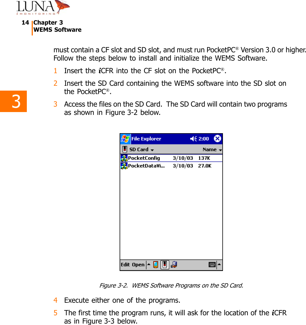


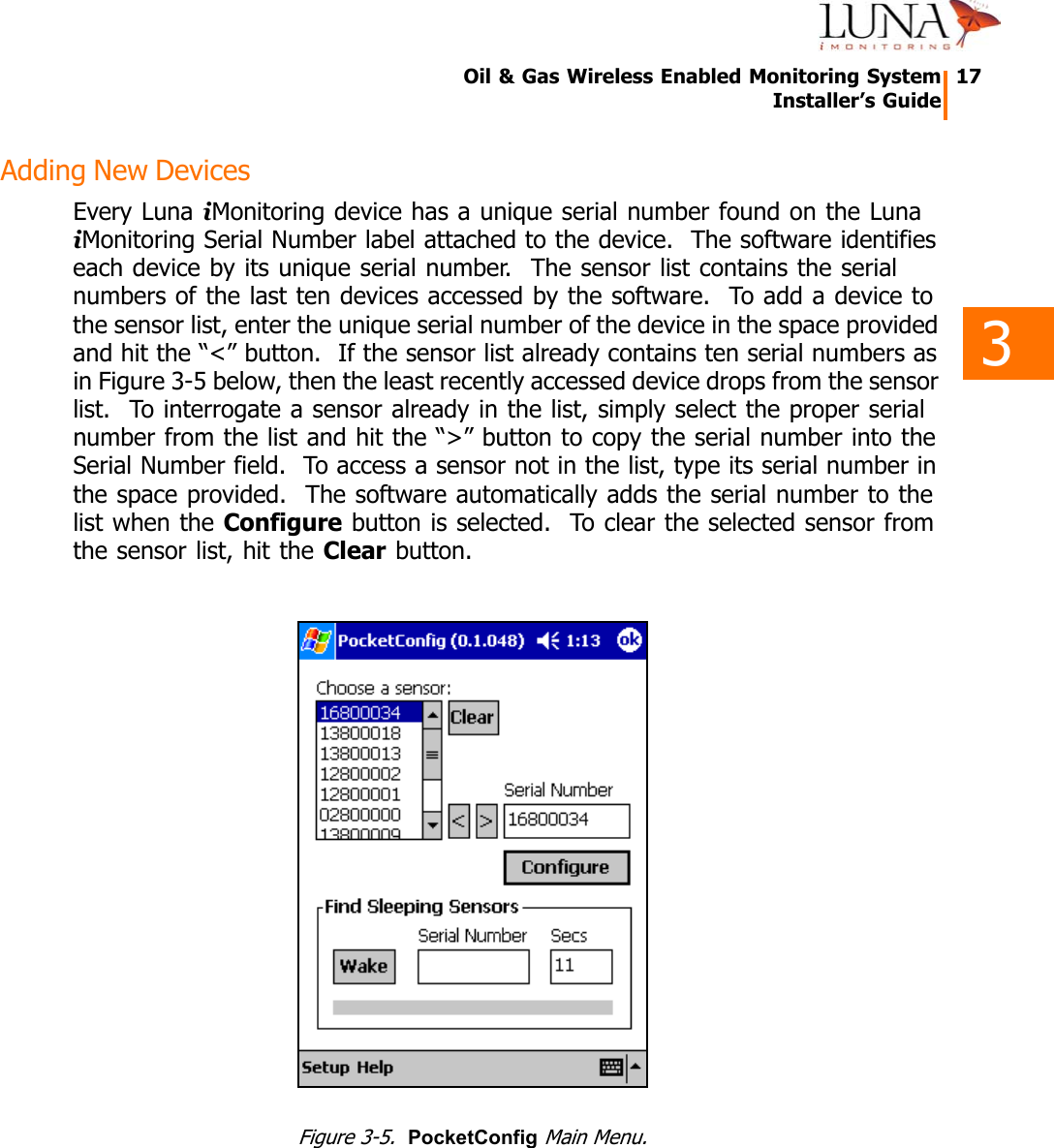
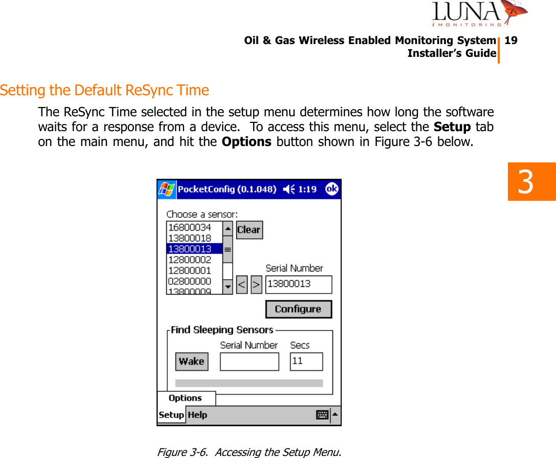
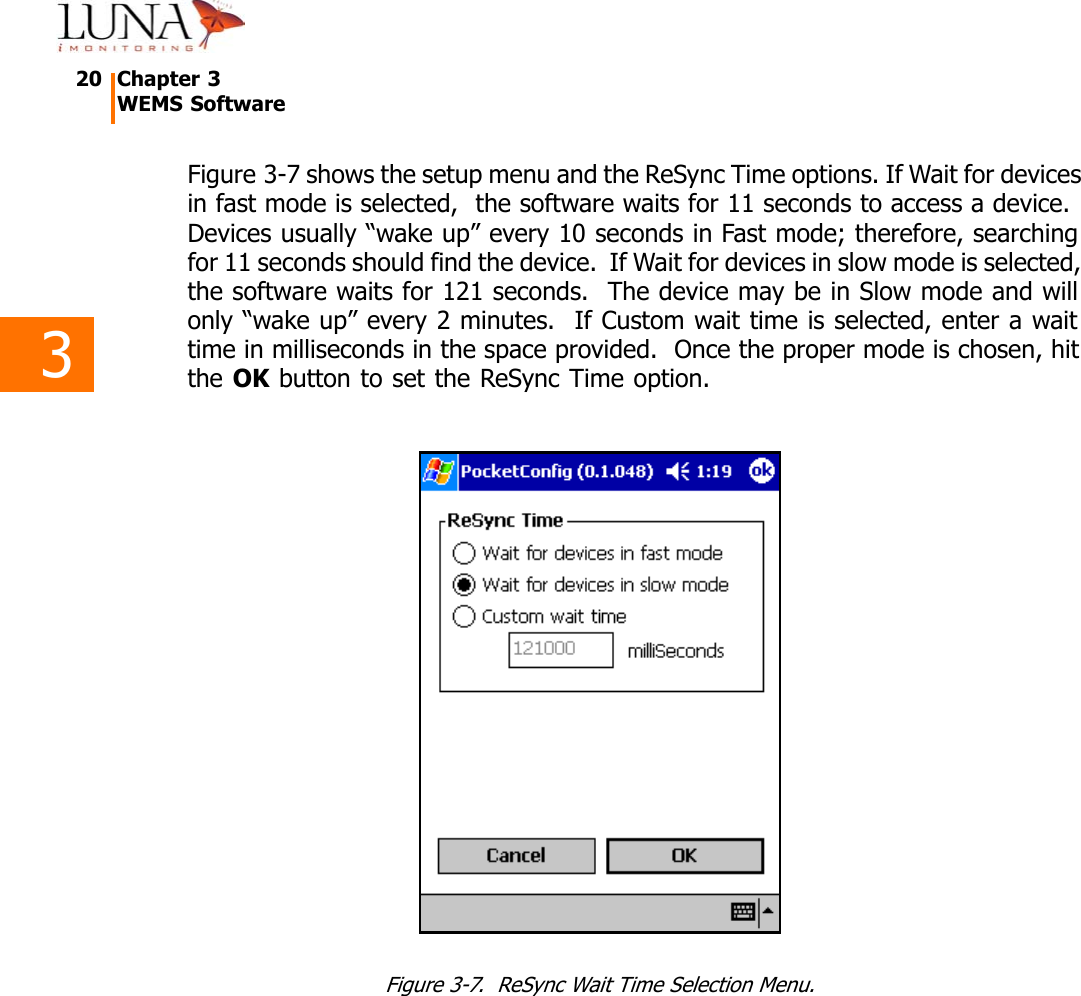

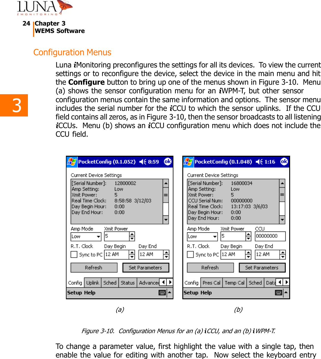
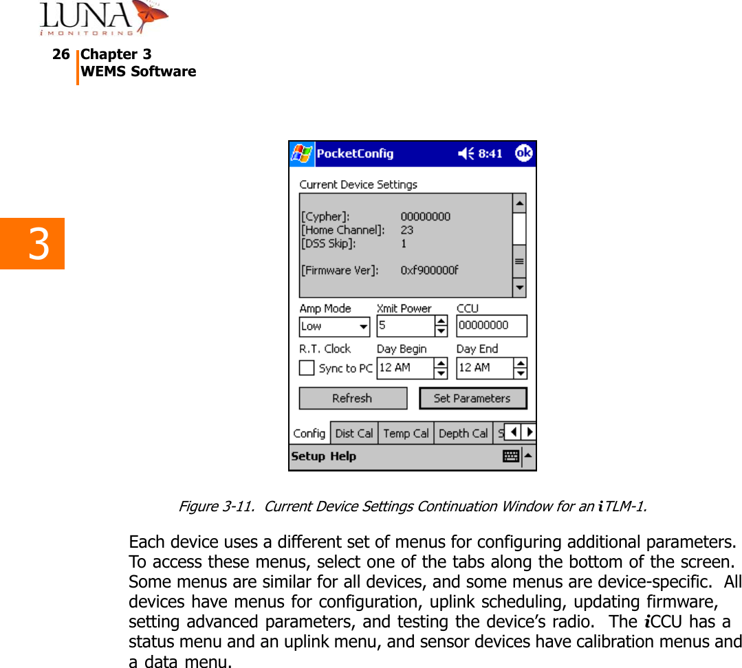
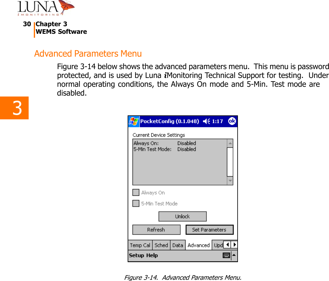
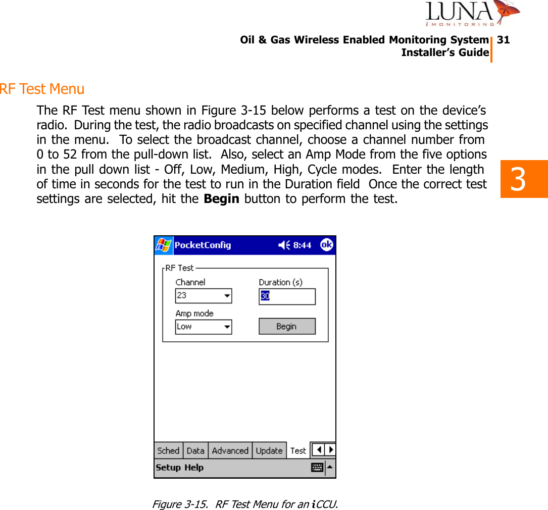
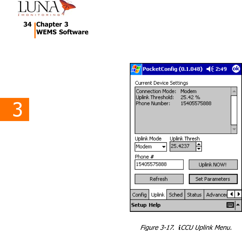
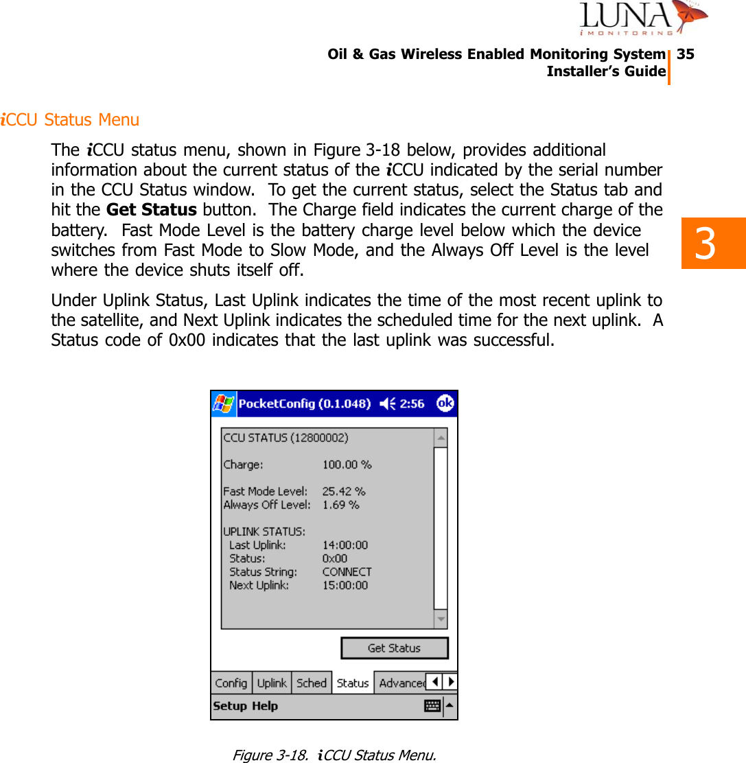
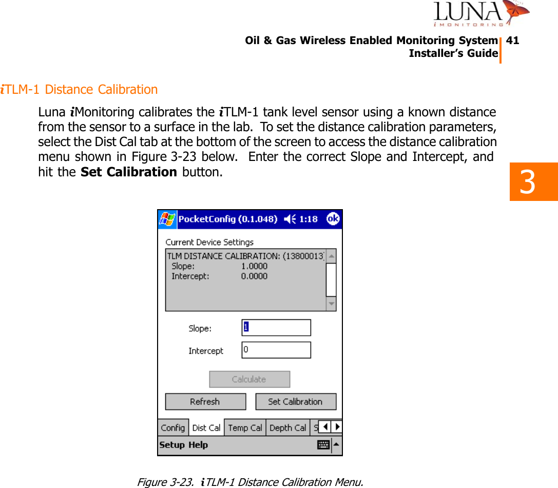
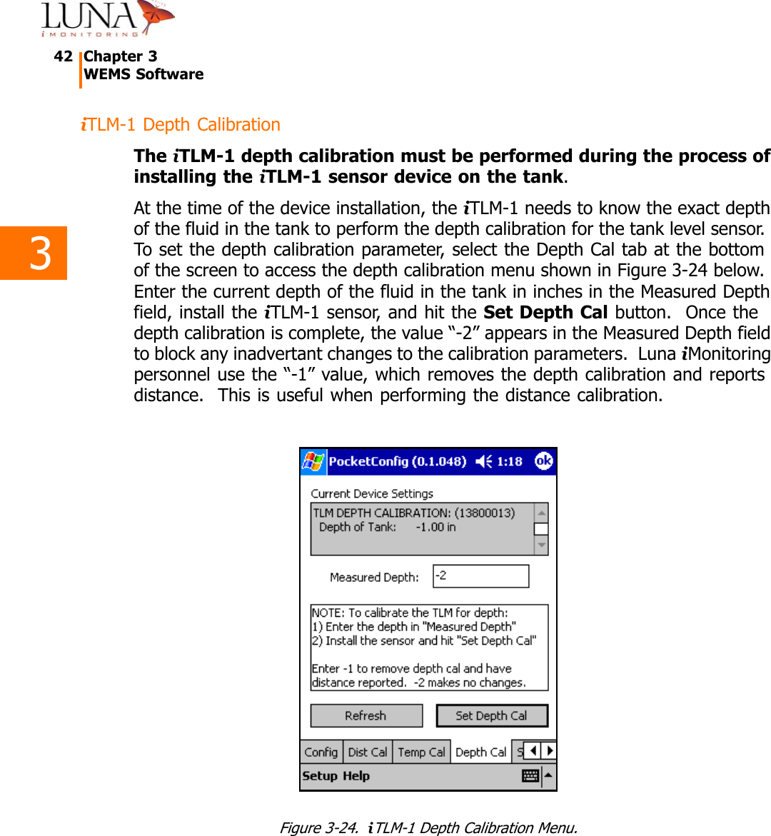
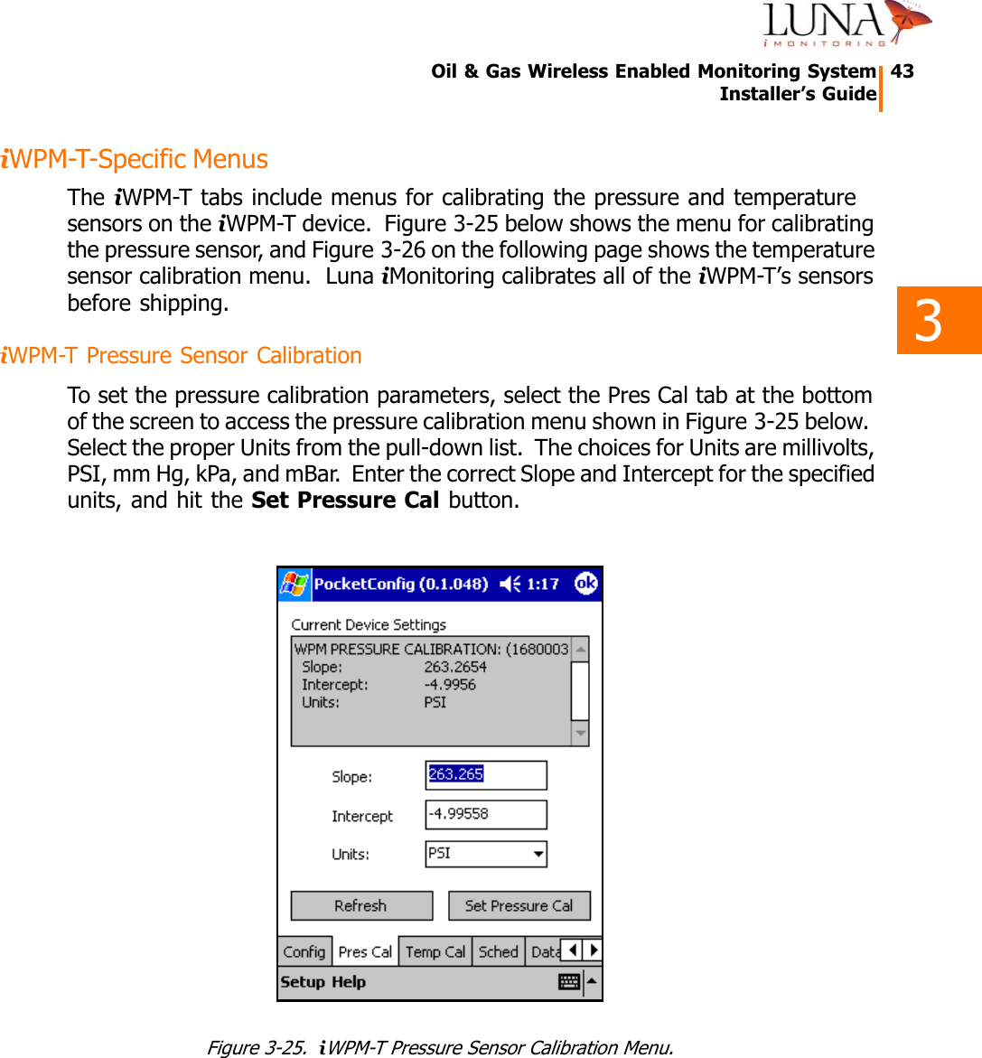
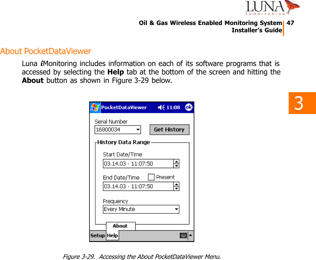
![33333333333333Oil & Gas Wireless Enabled Monitoring System 25Installer’s Guidescreen by tapping the keyboard icon at the bottom right of the screen. Use the keyboard to enter the new value. When finished entering the data, exit the keyboard by tapping the icon again. DO NOT USE THE “ENTER” KEY, as this will cause the application to exit. Once all the new parameter values are entered, hit the Set Parameters button to accept the changes. Parameters shown in brackets, [ ], in the Current Device Settings window may not be changed. The new values will appear in the Current Device Settings window.To change Amp Mode, select an option, Low/Medium/High, from the pull-down list. To change XmitPower, use the up/down arrows to the right of the field. To uplink a sensor to a specific iCCU, enter the serial number of the iCCU in the CCU field, or enter all zeros to broadcast to all iCCUs in listening range. The Sync to PC option synchronizes the Real Time Clock on the device to the clock on the PocketPC®. Use this option to synchronize all devices in the field to the same clock. Normally, Day Begin and Day End are set to 12:00 AM. To change these parameters, use the up/down arrows to the right of the field. These parameters only increment in 1-hour intervals.The Current Device Settings window provides other valuable information that is accessible using the scroll bar. Figure 3-11 below shows the Current Device Settings window for an iTLM-1 when scrolled down to reveal additional parameters. This other information includes:•the device serial number;•a 4-byte encryption key, called the cypher, which must be the same for all devices in a network;•the home channel that the device waits on when there is no activity, (when active the device scans all channels, 0-52);•the modulus through the scanning sequence, called the DSS skip, that can create additional sequences and must be the same for all devices in a network, (usually set to 1);•the version number of the device’s firmware.](https://usermanual.wiki/FB-iMonitoring/IMON.Manual-revised/User-Guide-367851-Page-30.png)