FB iMonitoring IMON Wireless Intelligent Monitors User Manual Manual revised
FB iMonitoring Wireless Intelligent Monitors Manual revised
Contents
- 1. Professional installation letter
- 2. Manual revised
Manual revised

Rhein Tech Laboratories, Inc. Client: Luna iMonitoring
360 Herndon Parkway Model Name/#: iEFM, iTLM-1, iWPM-T
Suite 1400 FCC ID: RIM-IMON
FCC: 15.247 Herndon, VA 20170
http://www.rheintech.com IC: RSS-210
Page 45 of 86
APPENDIX J: MANUAL
Please refer to the following pages.

Oil & Gas Wireless Enabled
Monitoring System
Installer’s Guide
Oil & Gas Wireless Enabled Monitoring System Installer’s Guide
Document version B.1
© 2003
Luna iMonitoring, Inc.
2903 Commerce Street, Suite A
Blacksburg, VA 24060
Phone: 540.557.5880
Fax: 540.951.0760
E-mail: solutions@lunaimonitoring.com
Web: www.lunaimonitoring.com
No portion of this publication may be reproduced or transmitted by any means without the written
permission of Luna iMonitoring, Inc.

1
1
1
1
1
1
1
1
1
1
1
1
1
1
iii
Contents
1Introduction
The Intelligent Wireless Sensor Suite . . . . . . . . . . . . . . . . . . . . . . . . . . . . . . . . . . . . . . 2
WEMS Components . . . . . . . . . . . . . . . . . . . . . . . . . . . . . . . . . . . . . . . . . . . . . . . . . . . . . 2
Concentration and Communications Unit (iCCU) . . . . . . . . . . . . . . . . . . . . . . . . . . . . . . . 4
Compact Flash Radio (iCFR) . . . . . . . . . . . . . . . . . . . . . . . . . . . . . . . . . . . . . . . . . . . . . 4
Electronic Flow Monitor (iEFM) . . . . . . . . . . . . . . . . . . . . . . . . . . . . . . . . . . . . . . . . . . . 4
Tank Level Monitor (iTLM-1) . . . . . . . . . . . . . . . . . . . . . . . . . . . . . . . . . . . . . . . . . . . . . 5
Wellhead Pressure Monitor (iWPM-T) . . . . . . . . . . . . . . . . . . . . . . . . . . . . . . . . . . . . . . . 5
Secure Digital (SD) Card . . . . . . . . . . . . . . . . . . . . . . . . . . . . . . . . . . . . . . . . . . . . . . . . 6
User-supplied Components . . . . . . . . . . . . . . . . . . . . . . . . . . . . . . . . . . . . . . . . . . . . . . . 6
2Installation
Site Selection for WEMS Components . . . . . . . . . . . . . . . . . . . . . . . . . . . . . . . . . . . . . . 7
Guidelines Concerning RF Signal Transmission . . . . . . . . . . . . . . . . . . . . . . . . . . . . . . . . 7
Guidelines Concerning Solar Panels . . . . . . . . . . . . . . . . . . . . . . . . . . . . . . . . . . . . . . . . 9
Guidelines Concerning Hazardous Environments . . . . . . . . . . . . . . . . . . . . . . . . . . . . . . . 9
Guidelines Concerning iTLM-1 Mounting . . . . . . . . . . . . . . . . . . . . . . . . . . . . . . . . . . . 10
Pre-installation iTLM-1 Depth Calibration . . . . . . . . . . . . . . . . . . . . . . . . . . . . . . . . . . 11
Installation Instructions . . . . . . . . . . . . . . . . . . . . . . . . . . . . . . . . . . . . . . . . . . . . . . . . 11
Monitor Installation Instructions . . . . . . . . . . . . . . . . . . . . . . . . . . . . . . . . . . . . . . . . . 11
iCCU Installation Instructions . . . . . . . . . . . . . . . . . . . . . . . . . . . . . . . . . . . . . . . . . . . 12
3 WEMS Software
Installing the WEMS Software . . . . . . . . . . . . . . . . . . . . . . . . . . . . . . . . . . . . . . . . . . . 13

1
1
1
1
1
1
1
1
1
1
1
1
1
1
iv Contents
Sensor Charge Modes . . . . . . . . . . . . . . . . . . . . . . . . . . . . . . . . . . . . . . . . . . . . . . . . 18
iCCU Uplink Menu . . . . . . . . . . . . . . . . . . . . . . . . . . . . . . . . . . . . . . . . . . . . . . . . 33
iEFM Sensor Calibration . . . . . . . . . . . . . . . . . . . . . . . . . . . . . . . . . . . . . . . . . . . . 36
iEFM Gas Calibration . . . . . . . . . . . . . . . . . . . . . . . . . . . . . . . . . . . . . . . . . . . . . . 37
iEFM Sensor Data . . . . . . . . . . . . . . . . . . . . . . . . . . . . . . . . . . . . . . . . . . . . . . . . 37
iTLM-1 Temperature Calibration . . . . . . . . . . . . . . . . . . . . . . . . . . . . . . . . . . . . . . 39
iWPM-T Pressure Sensor Calibration . . . . . . . . . . . . . . . . . . . . . . . . . . . . . . . . . . . 43
iWPM-T Temperature Calibration . . . . . . . . . . . . . . . . . . . . . . . . . . . . . . . . . . . . . . 44
Setting the Default ReSync Time . . . . . . . . . . . . . . . . . . . . . . . . . . . . . . . . . . . . . . . . 45
Exiting the Software . . . . . . . . . . . . . . . . . . . . . . . . . . . . . . . . . . . . . . . . . . . . . . . . . . . 53
A Specifications
B Technical Support
C Using the Charge Cable
1
1
1
1
1
1
1
1
1
1
1
1
1
1
1
Chapter 1
Introduction
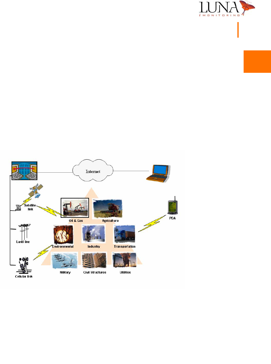
Figure 1-1. Applications for Luna
i
Monitoring’s Intelligent Wireless Sensor Suite
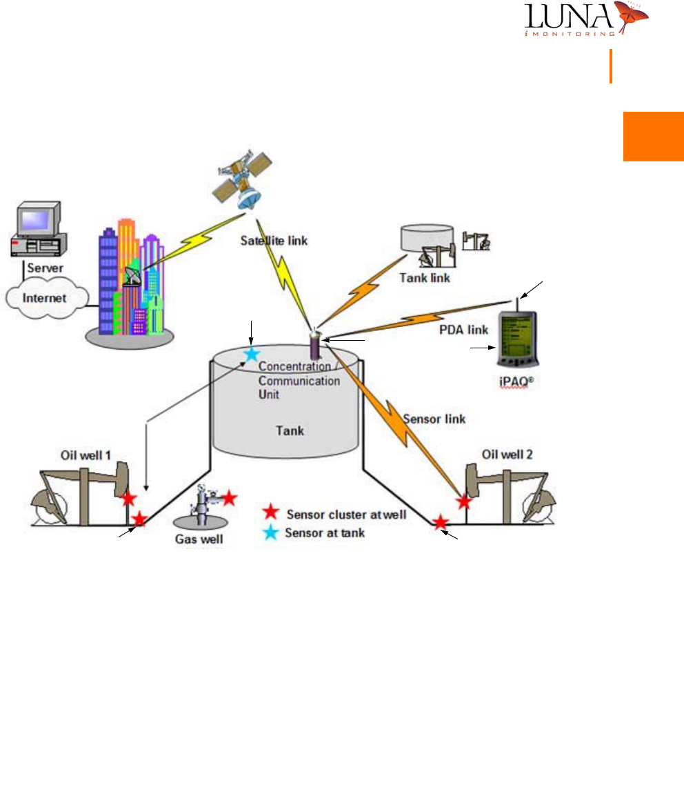
The Luna iMonitoring Oil and Gas Wireless Enabled Monitoring System (WEMS)
is a network of monitors and computers used to collect production data within
an oil field environment. Sensor and communication modules collect and transmit
data via wireless RF and satellite links. These modules are part of Luna
iMonitoring’s Intelligent Wireless Sensor Suite.

1
1
1
1
1
1
1
1
1
1
1
1
1
1
2Chapter 1
Introduction
The wireless oil field provides innovative, low-cost, remote asset management.
Some of the advantages of wireless sensing include
•reduce cost for field labor and transportation;
•reduce administration cost for recording, generating, and distribut-
ing reports;
•provide better information to the Production Engineer for decision
making;
•provide more efficient tasking of the Pumper;
•enhance revenue through optimized well performance and reduced
downtime.
The Intelligent Wireless Sensor Suite
Luna iMonitoring’s Intelligent Wireless Sensor Suite includes sensors, computers,
software, and communication devices to collect and transmit data in a variety of
industries and applications. The iMonitoring “smart” sensors use local processing
to minimize power consumption and communication bandwidth. Intelligent
software collects, processes, and stores the data in an information database. The
iMonitoring system uses RF, cellular, Internet, and satellite links to transmit data
between sensors, data collection sites, and central computers. For more
information on the Intelligent Wireless Sensor Suite and its components, please
visit the Luna iMonitoring web site at www.lunaimonitoring.com
WEMS Components
The current configuration of the WEMS includes one or more of each of the
following components:
•Concentration and Communications Unit (iCCU),
•Compact Flash Radio (iCFR),
•Electronic Flow Monitor (iEFM)
•Tank Level Monitor (iTLM-1),
•Wellhead Pressure Monitor (iWPM-T),
•Secure Digital (SD) Card containing the WEMS Software.
1
1
1
1
1
1
1
1
1
1
1
1
1
1
4Chapter 1
Introduction
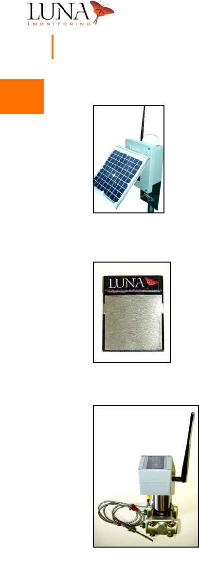
Concentration and Communications Unit (iCCU)
The Luna iMonitoring iCCU is an autonomous,
wireless-LAN-to-wireless-WAN bridge, and data storage and
collection unit. Data flows via a secure, bidirectional, local radio
link. The iCCU can perform on-board data storage and
processing, and can serve as a LAN repeater. It contains external
WAN and LAN antenna ports. A single, solar-assisted battery
powers the unit which optimizes power based on the current
energy storage. The iCCU supports up to 128 wireless sensors,
and is field configurable and upgradeable.
Compact Flash Radio (iCFR)
The Luna iMonitoring iCFR is a self-contained Type I Compact
Flash Radio for wireless sensing applications. The iCFR uses
a standard interface found on PocketPC®s. The unit
communicates with other iCFRs, iCCUs, and iMonitoring’s
sensors over a customizable, wireless interface. The iCFR does
not require a battery since the host unit provides power. Other
features include programmable output power, low cost, and the
ability to configure and upgrade the unit in the field.
Electronic Flow Monitor (iEFM)
The Luna iMonitoring iEFM is an autonomous, wireless
electronic flow monitor which monitors natural gas flow
and provides total volumetric flow rate. Typically, the
sensor acquires five flow readings per day in monitor
mode. Each reading consists of an instantaneous
measurement, an average over the previous hour, and an
average over the previous 24 hours. An iCCU may
interrogate an iEFM at any time within a range of 2500
feet, and a portable device, such as a PocketPC®, can poll
the unit within a range of 500 feet.The iEFM performs
on-board data storage and processing, and transmits over
a secure, bidirectional radio link. The unit optimizes power
1
1
1
1
1
1
1
1
1
1
1
1
1
1
Oil & Gas Wireless Enabled Monitoring System 5
Installer’s Guide
based on the current energy storage, and requires only a single, solar-assisted
battery. The iEFM is easy to install, and is field configurable and upgradeable.
The unit incorporates an IP65 ruggedized enclosure and meets UL-913 certification
requirements for an intrinsically safe device in Class I, Division 1, Groups C and
D hazardous areas.
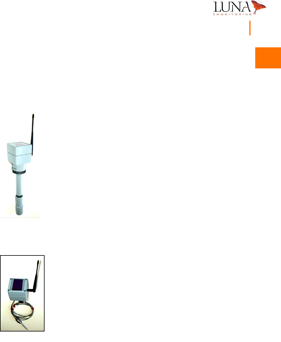
Tank Level Monitor (iTLM-1)
The Luna iMonitoring iTLM-1 is a self-contained, wireless tank
level monitor using Ultrasonic Sensing Technology to provide
temperature-compensated fluid level measurements in tanks and
silos. Typically, the sensor acquires five pressure readings per
day in monitor mode. An iCCU can communicate with a iTLM-1
within a range of 2500 feet, and a portable device, such as a
PocketPC®, can poll the unit within a range of 500 feet.The iTLM-1
performs on-board data storage and processing, and transmits
over a secure, bidirectional radio link. The unit optimizes power
based on the current energy storage, and requires only a single,
solar-assisted battery. The iTLM-1 is easy to install, and is field
configurable and upgradeable. The unit incorporates an IP65
ruggedized enclosure and meets UL-913 certification requirements
for an intrinsically safe device in Class I, Division 1, Groups C and
D hazardous areas.
Wellhead Pressure Monitor (iWPM-T)
The Luna iMonitoring iWPM-T is an autonomous, wireless
pressure monitor for sensing pressure at the wellhead in oil and
gas applications. Typically, the sensor acquires five pressure and
temperature readings per day in monitor mode. An iCCU may
interrogate an iWPM-T at any time within a range of 2500 feet,
and a portable device, such as a PocketPC®, can poll the unit
within a range of 500 feet.The iWPM-T performs on-board data
storage and processing, and transmits over a secure,
bidirectional radio link. The unit optimizes power based on the
current energy storage, and requires only a single, solar-assisted
battery. The iWPM-T is easy to install, and is field configurable

1
1
1
1
1
1
1
1
1
1
1
1
1
1
6Chapter 1
Introduction
and upgradeable. The unit incorporates an IP65 ruggedized enclosure and meets
UL-913 certification requirements for an intrinsically safe device in Class I, Division
1, Groups C and D hazardous areas.
Secure Digital (SD) Card
The SD Card supplied with the system contains the WEMS Software
for a PocketPC® running version 3.0 of the PocketPC® operating
system. The SD Card plugs into the standard SD slot found on all
PocketPC®s. The WEMS Software requires a one-time installation
per PocketPC®, and includes programs for defining, accessing, and
interrogating multiple iMonitoring devices. Chapter 3‚ “WEMS
Software,” on page 13, includes a detailed discussion on the
installation and use of the WEMS Software.
User-supplied Components
For on-demand sensor measurements and data acquisition in the field,
the user must supply a PocketPC®, such as the one shown at the left,
to interrogate the iCCU, iWPM-T, and iTLM-1. The PocketPC® must
have a CF Card slot to accommodate the iCFR, and an SD slot for the
WEMS Software SD Card.

2
2
2
2
2
2
2
2
2
2
2
2
2
2
7
Chapter 2
Installation
The components in Luna iMonitoring’s Intelligent Wireless Sensor Suite are easy
to install using simple tools. The installation guidelines in this manual outline the
steps for selecting the proper site for the device, and for handling, mounting and
activating the device.
Site Selection for WEMS Components
The iTLM-1 and iWPM-T sensor modules mount directly onto oil and gas tanks,
pipelines, and wellheads in the field. The iCCU mounts on a variety of structures
in and around the oil field. Issues affecting the site selected for installation include
obstructions in the line-of-sight between the sensor module and the iCCU; distance
from the sensor module to an iCCU; height of the iCCU; proximity of the
component to other electronic equipment or large metal objects that may affect
the transmission of radio signals; orientation of the solar panels on the component;
hazardous environmental conditions; and the surface mounting angle of the tank
for the iTLM-1 installation.
Guidelines Concerning RF Signal Transmission
Luna iMonitoring’s sensor modules use RF signals to communicate with iCCUs
and PocketPC®s. Following the guidelines below maximizes the range over which
the WEMS components will be able to transmit signals.
•Place the sensor module in the direct line-of-sight with the iCCU,
whenever possible. A direct line-of-sight between the sensor module
and the iCCU provides optimal signal transmission and reception.

2
2
2
2
2
2
2
2
2
2
2
2
2
2
8Chapter 2
Installation
With a direct line-of-sight, the WEMS components communicate up
to 2500 feet. However, without a direct line-of-sight, this distance
decreases.
•Place the iCCU as high as possible to improve signal transmission
and reception.
•Avoid placing sensor modules and iCCUs near electrical equipment
or large metal objects. Electrical devices, such as large electric
motors, power lines, antennas, and electric fences cause electro-
magnetic interference that adversely affect signal quality. Large
metal objects, which are electrically conductive, reflect and scatter
radio signals when placed between two RF-linked modules.
The Luna iMonitoring sensor modules, iCFR, and iCCU meet FCC requirements
for CFR 47 Part 15, which dictate that operation of the device is subject to the
following two conditions:
1The device will not cause harmful interference, and
2The device must accept any interference received, including interference
that may cause undesired operation.
Because the device meets FCC requirements for CFR 47 Part 15, the customer
requires no operating license to transmit radio signals using the device.
The Luna iMonitoring iTLM-1 sensor module utilizes ultrasonic technology and is
subject to the following additional authorization: Verification as a non-consumer
ISM device as specified by Part 18.
The Luna iMonitoring iCCU is subject to the following additional authorization:
Verification as a transmitter as specified by Part 25.
Any changes or modifications not expressly approved by the manufacturer will
void the user’s authority to operate the equipment.
Every radio-linked device in the Luna iMonitoring Intelligent Wireless Sensor Suite
carries a label. Figure 2-1 below shows a typical label for a sensor device which
includes the Model Number of the device, the FCC ID Number, the UL certification,
the FCC certification(s), and the Serial Number.

2
2
2
2
2
2
2
2
2
2
2
2
2
2
Oil & Gas Wireless Enabled Monitoring System 9
Installer’s Guide
Figure 2-1. Typical Label Found on all Luna
i
Monitoring Radio-linked Devices.
Guidelines Concerning Solar Panels
All of Luna iMonitoring’s sensor modules and iCCUs employ a single, solar-assisted
battery for power. Properly orienting the solar panels on the WEMS component
achieves a maximum battery life of more than two years. Place the component
in a non-shaded area with the solar panels facing toward the sun. Also, ensure
that the site chosen will not become shaded due to tree growth or installation of
other structures.
Guidelines Concerning Hazardous Environments
Luna iMonitoring sensor modules mount directly onto structures such as a tanks,
pipelines, or wellheads located in hazardous areas. These sensor modules (iEFM,
iTLM-1, and iWPM-T) are, by design, intrinsically safe and meet the standard for
UL-913 certification for Class I, Division 1, Groups C and D hazardous areas. By
definition, an intrinsically safe apparatus is one in which all the circuits are
intrinsically safe; and an intrinsically safe circuit is one in which any spark or
thermal effect is incapable of causing ignition of a mixture of flammable or
combustible material in air under prescribed test conditions, according to the
National Electrical Code.
The iCCU mounts onto structures outside the hazardous zones in the oil field;
for example, an area greater than 3 meters from an oil tank.
2
2
2
2
2
2
2
2
2
2
2
2
2
2
10 Chapter 2
Installation
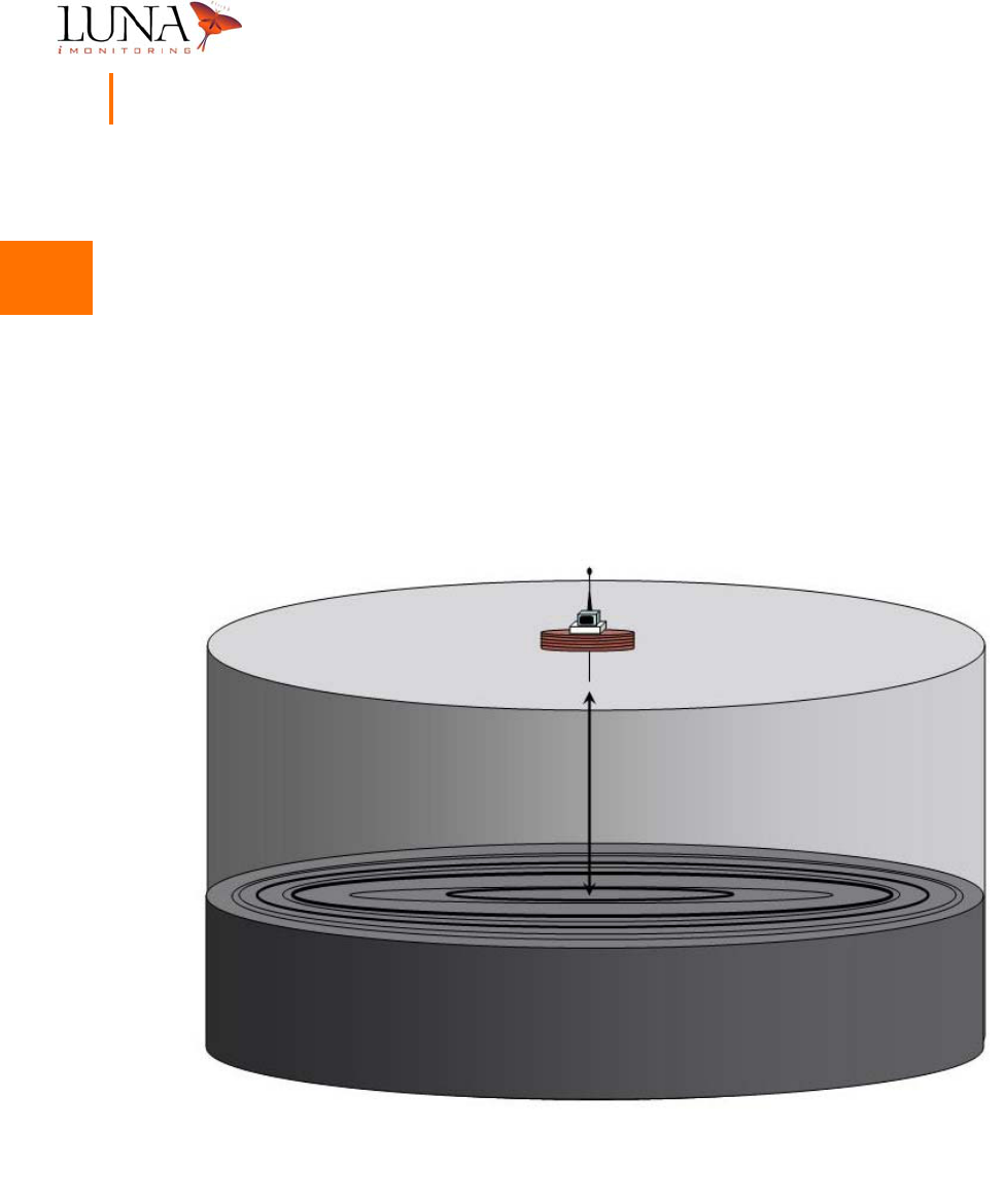
Guidelines Concerning iTLM-1 Mounting
The iTLM-1 uses Ultrasonic Sensing Technology to provide tank fluid level
measurements. The sensor projects an ultrasonic beam at the surface of the liquid
in a tank. The beam reflects off the liquid’s surface back to the sensor. The
iTLM-1 acquires the raw measurement and then compensates for the effects of
temperature on the raw data. To properly measure the fluid level in the tank,
the sensor must be mounted such that the path of the ultrasonic beam is
perpendicular to the fluid surface. A mounting angle greater than 5 degrees may
cause erroneous data. Figure 2-2 below provides a rendering of a properly
installed iTLM-1 sensor module.
Figure 2-2. Proper Mounting Angle for the
i
TLM-1 Sensor

2
2
2
2
2
2
2
2
2
2
2
2
2
2
Oil & Gas Wireless Enabled Monitoring System 11
Installer’s Guide
Pre-installation iTLM-1 Depth Calibration
Before installing the iTLM-1 sensor device on a tank, perform the iTLM-1 depth
calibration procedure. See the Section entitled, “iTLM-1 Depth Calibration” on
page 42 of Chapter 3, “WEMS Software”, for details.
Installation Instructions
When installing any of the iMonitoring wireless devices care must be taken to
guarantee that the wireless devices are installed and provisioned in its intended
configuration and the installation guarantees compliance to regulatory and safety
requirements.
Monitor Installation Instructions
The following instructions are to be performed for each monitor (iEFM, iTLM-1,
and iWPM-T) at installation.
1Remove the monitor packing carton.
2Remove the reset button access screw (Phillips head) on the bottom
of the unit, and using a non-metalic probe, press and hold the reset
button momentarily to bring the unit out of the sleep mode. Replace
the screw.
3Install the antenna onto the SMA connector on the monitor.
4On the iEFM and iWPM-T, install the temperature sensor on the monitor.
5Using the WEMS Software module PocketConfig, enter the monitor’s
unique serial number and press the Configure button to enter the
unit-level configuration. Refer to Chapter 3‚ “WEMS Software,” on
page 13 for more information on using PocketConfig.
6In the resulting Config tab screen, enter the following information:

2
2
2
2
2
2
2
2
2
2
2
2
2
2
12 Chapter 2
Installation
aEnter a value of -3 for the parameter Xmit Power if the antenna
supplied with the unit is the Nearson S467AH-915S Omni whip
antenna. Enter a value of -6 for Xmit Power if the antenna is
the Bluewave EDY-9432 Yagi antenna. FCC compliance requires
these power settings.
bEnable the function Sync to PC by ‘checking’ (D) this parameter.
Once the proper value for Xmit Power is entered and Sync to PC is enabled,
select the Set Parameters button and wait for the progress screen to
complete.
7Verify that the settings were accepted by checking the Current Device
Settings window.
iCCU Installation Instructions
The following instructions are to be performed for the iCCU at installation.
1Remove the iCCU packing carton.
2Remove the enclosure cover. Locate the unattached red wire and attach
it to the positive terminal on the battery. Replace the cover.
3Using the WEMS Software module PocketConfig, enter the iCCU’s
unique serial number and press the Configure button to enter the
unit-level configuration. Refer to Chapter 3‚ “WEMS Software,” on
page 13 for more information on using PocketConfig.
4In the resulting Config tab screen, enable the function Sync to PC by
‘checking’ (D) this parameter. Once Sync to PC is enabled, select the
Set Parameters button and wait for the progress screen to complete.
5Verify that the setting was accepted by checking the Current Device
Settings window.

3
3
3
3
3
3
3
3
3
3
3
3
3
3
13
Chapter 3
WEMS Software
The WEMS Software is a multi-purpose, menu-driven program for configuring and
accessing all modules in Luna iMonitoring’s Intelligent Wireless Sensor Suite. Once
properly configured using the WEMS Software, the devices run autonomously
based on the scheduling parameters set in the software. The WEMS Software
also provides in-the-field access to any device. The following sections include
procedures for initializing all WEMS modules, and instructions for interrogating
these devices in the field.
Installing the WEMS Software
Figure 3-1. (a) SD Card; (b)
i
CFR
The WEMS Software runs on a PocketPC® using the SD Card provided by Luna
iMonitoring. The PocketPC® communicates with the sensors and iCCUs using the
iCFR also provided by Luna iMonitoring. The user supplies the PocketPC®, which
(a) (b)
3
3
3
3
3
3
3
3
3
3
3
3
3
3
14 Chapter 3
WEMS Software
must contain a CF slot and SD slot, and must run PocketPC® Version 3.0 or higher.
Follow the steps below to install and initialize the WEMS Software.
1Insert the iCFR into the CF slot on the PocketPC®.
2Insert the SD Card containing the WEMS software into the SD slot on
the PocketPC®.
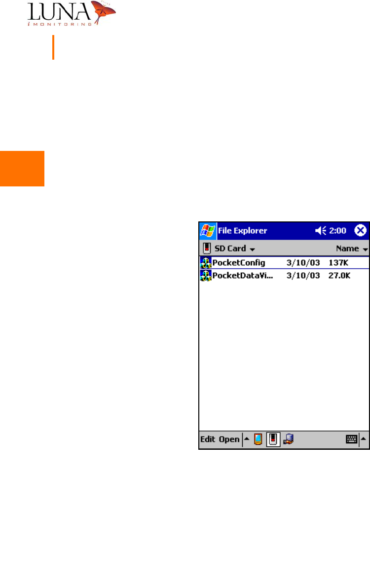
3Access the files on the SD Card. The SD Card will contain two programs
as shown in Figure 3-2 below.
Figure 3-2. WEMS Software Programs on the SD Card.
4Execute either one of the programs.
5The first time the program runs, it will ask for the location of the iCFR
as in Figure 3-3 below.

3
3
3
3
3
3
3
3
3
3
3
3
3
3
Oil & Gas Wireless Enabled Monitoring System 15
Installer’s Guide
Figure 3-3.
i
CFR Serial Port Selection Menu.
Typically, the CF slot is located on COM2 or higher. Select COM2 from the
Serial Port pull-down list and click OK. If the iCFR is on COM2, the program’s
main menu will open. If the iCFR in not on COM2, the program will return
to the Start menu and wait for another port selection. Try other available
ports until the program finds the iCFR port and opens the main menu.
3
3
3
3
3
3
3
3
3
3
3
3
3
3
16 Chapter 3
WEMS Software
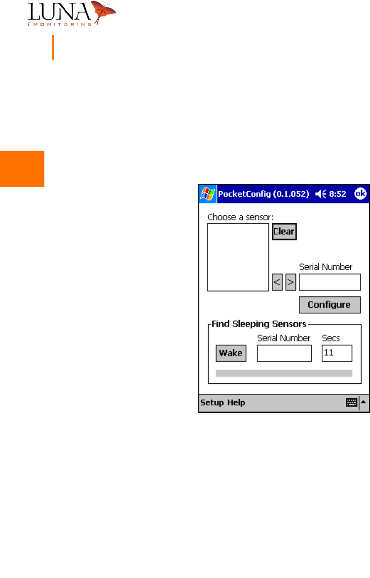
PocketConfig
The program PocketConfig includes menus for configuring and interrogating
devices. Before the PocketPC® can communicate with sensor and communication
devices, it must have certain information about the device. Therefore, the
software will not list any sensors at initial start-up of the program as in Figure 3-4.
Figure 3-4.
PocketConfig
Main Menu with No Defined Devices.
3
3
3
3
3
3
3
3
3
3
3
3
3
3
Oil & Gas Wireless Enabled Monitoring System 17
Installer’s Guide
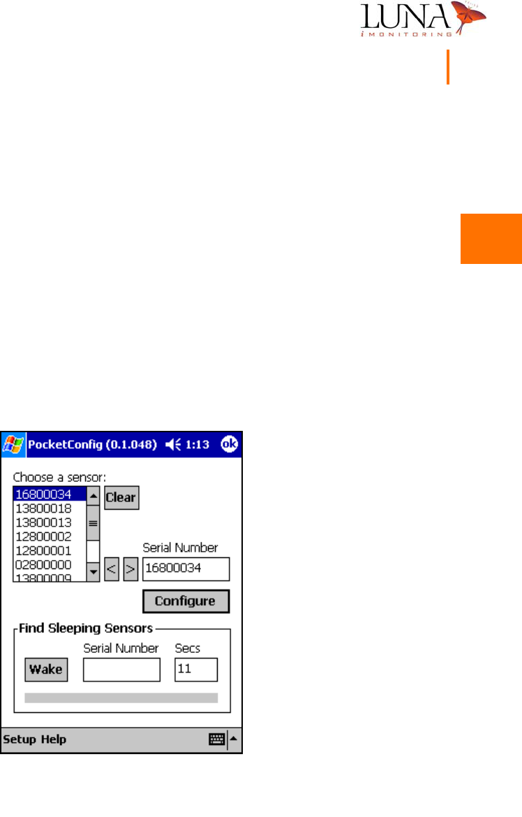
Adding New Devices
Every Luna iMonitoring device has a unique serial number found on the Luna
iMonitoring Serial Number label attached to the device. The software identifies
each device by its unique serial number. The sensor list contains the serial
numbers of the last ten devices accessed by the software. To add a device to
the sensor list, enter the unique serial number of the device in the space provided
and hit the “<” button. If the sensor list already contains ten serial numbers as
in Figure 3-5 below, then the least recently accessed device drops from the sensor
list. To interrogate a sensor already in the list, simply select the proper serial
number from the list and hit the “>” button to copy the serial number into the
Serial Number field. To access a sensor not in the list, type its serial number in
the space provided. The software automatically adds the serial number to the
list when the Configure button is selected. To clear the selected sensor from
the sensor list, hit the Clear button.
Figure 3-5.
PocketConfig
Main Menu.

3
3
3
3
3
3
3
3
3
3
3
3
3
3
18 Chapter 3
WEMS Software
Sensor Charge Modes
Sensor devices have four charge modes based on the current charge capacity of
the device’s battery. The four modes are
•Always On mode, when the battery is at 100%;
•Fast mode, when the battery is above 76.7% but below 100%;
•Slow mode, when the battery is at or below 76.7% but above 0%;
•Always Off mode, when the battery is fully discharged.
The device stays on continually in Always On mode which usually occurs on sunny
days when the solar panels can power the device and keep the battery fully
charged. In Fast mode the device “wakes up” every 10 seconds to see if it is
being interrogated. In Slow mode the device only wakes up every 2 minutes.
If the battery becomes fully discharged, then the device shuts off completely.
3
3
3
3
3
3
3
3
3
3
3
3
3
3
Oil & Gas Wireless Enabled Monitoring System 19
Installer’s Guide
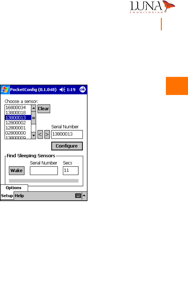
Setting the Default ReSync Time
The ReSync Time selected in the setup menu determines how long the software
waits for a response from a device. To access this menu, select the Setup tab
on the main menu, and hit the Options button shown in Figure 3-6 below.
Figure 3-6. Accessing the Setup Menu.
3
3
3
3
3
3
3
3
3
3
3
3
3
3
20 Chapter 3
WEMS Software
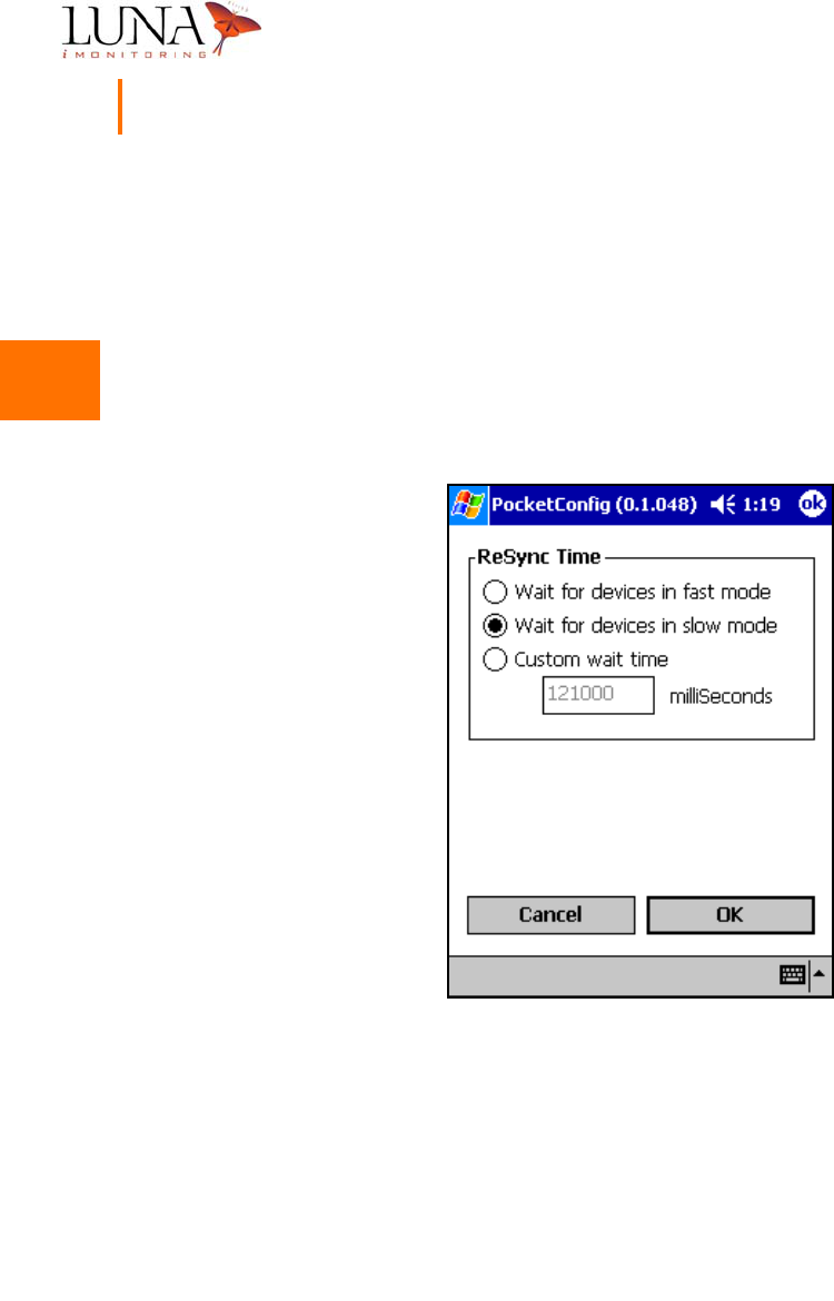
Figure 3-7 shows the setup menu and the ReSync Time options. If Wait for devices
in fast mode is selected, the software waits for 11 seconds to access a device.
Devices usually “wake up” every 10 seconds in Fast mode; therefore, searching
for 11 seconds should find the device. If Wait for devices in slow mode is selected,
the software waits for 121 seconds. The device may be in Slow mode and will
only “wake up” every 2 minutes. If Custom wait time is selected, enter a wait
time in milliseconds in the space provided. Once the proper mode is chosen, hit
the OK button to set the ReSync Time option.
Figure 3-7. ReSync Wait Time Selection Menu.

3
3
3
3
3
3
3
3
3
3
3
3
3
3
Oil & Gas Wireless Enabled Monitoring System 21
Installer’s Guide
Finding Sleeping Devices
If a known device does not respond when interrogated, the device may be
“sleeping”, and the Resync Time may be set to only wait for devices in fast mode.
By default, the software searches for the device for the time interval specified in
the setup menu. To wake a sleeping device, enter its serial number in the
appropriate space under Find Sleeping Sensors in the main menu, and hit the
Wake button. If the software still does not find the sleeping device, increase
the search time to 121 seconds. If the software fails to find the device after 121
seconds, check the device for possible battery failure. Using Find Sleeping Sensors
overrides the time interval selected in the setup menu.
Note: Find Sleeping
Sensors wakes the device and places it temporarily in Always On mode which
significantly increases power consumption.
3
3
3
3
3
3
3
3
3
3
3
3
3
3
22 Chapter 3
WEMS Software
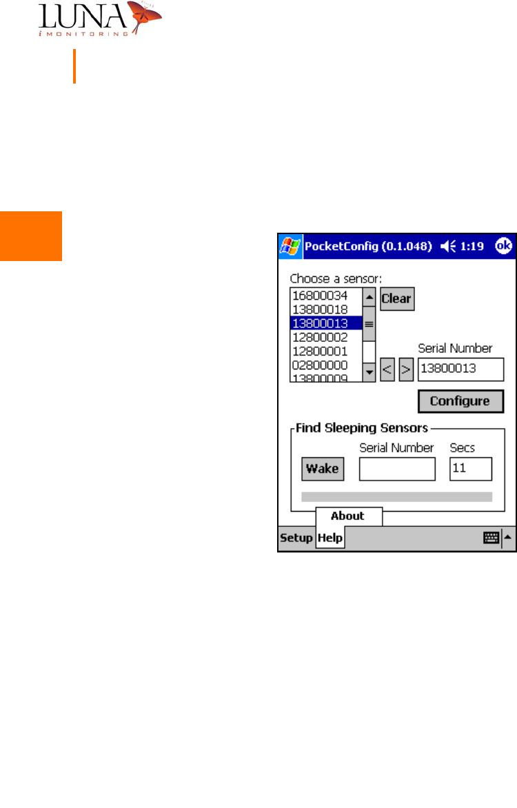
About PocketConfig
Luna iMonitoring includes information on each of its software programs that is
accessed by selecting the Help tab at the bottom of the screen and hitting the
About button as shown in Figure 3-8 below.
Figure 3-8. Accessing the About PocketConfig Menu.
3
3
3
3
3
3
3
3
3
3
3
3
3
3
Oil & Gas Wireless Enabled Monitoring System 23
Installer’s Guide
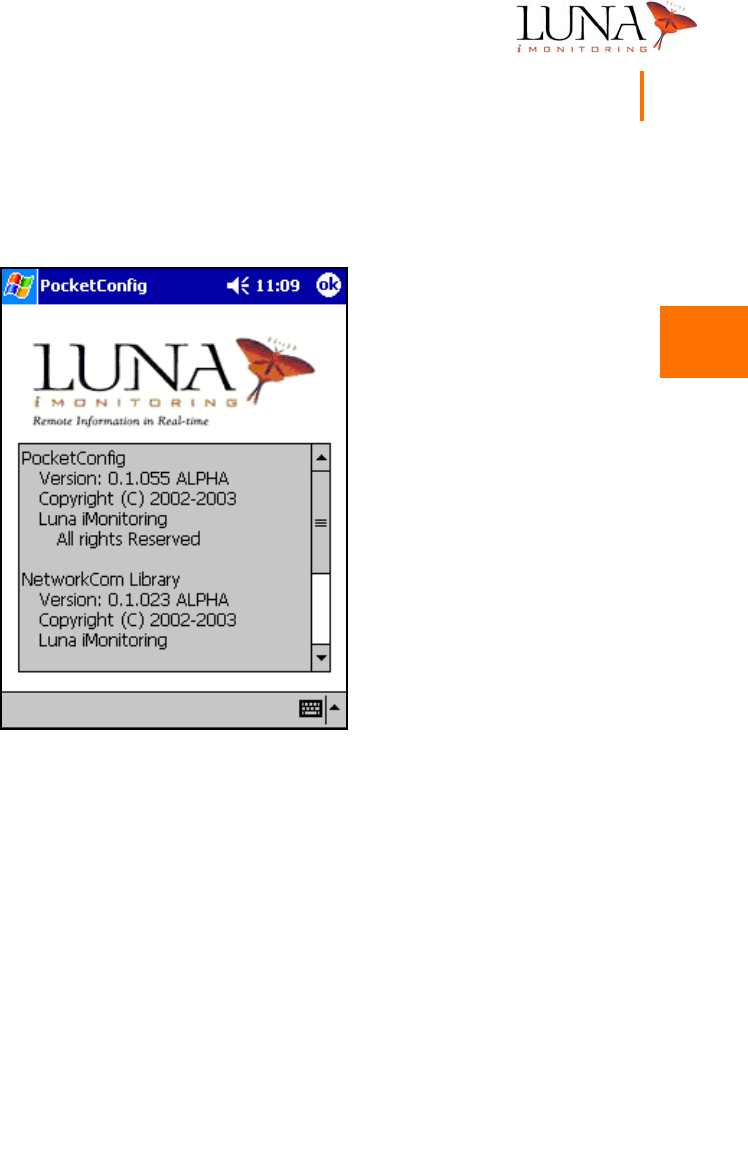
This window provides copyright and version information on the program and
library software.
Figure 3-9. Detailed Information on PocketConfig.
3
3
3
3
3
3
3
3
3
3
3
3
3
3
24 Chapter 3
WEMS Software
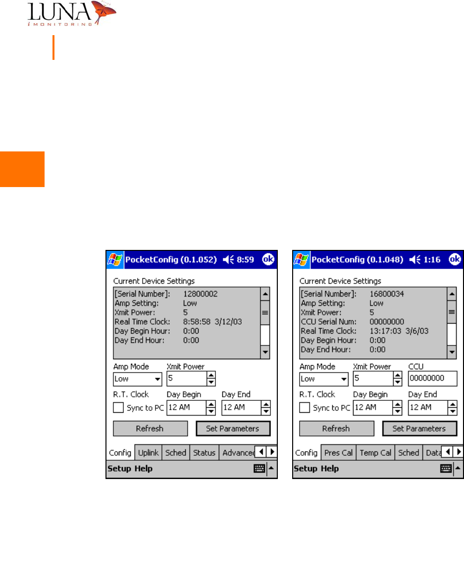
Configuration Menus
Luna iMonitoring preconfigures the settings for all its devices. To view the current
settings or to reconfigure the device, select the device in the main menu and hit
the Configure button to bring up one of the menus shown in Figure 3-10. Menu
(a) shows the sensor configuration menu for an iWPM-T, but other sensor
configuration menus contain the same information and options. The sensor menu
includes the serial number for the iCCU to which the sensor uplinks. If the CCU
field contains all zeros, as in Figure 3-10, then the sensor broadcasts to all listening
iCCUs. Menu (b) shows an iCCU configuration menu which does not include the
CCU field.
Figure 3-10. Configuration Menus for an (a)
i
CCU, and an (b)
i
WPM-T.
To change a parameter value, first highlight the value with a single tap, then
enable the value for editing with another tap. Now select the keyboard entry
(a) (b)

3
3
3
3
3
3
3
3
3
3
3
3
3
3
Oil & Gas Wireless Enabled Monitoring System 25
Installer’s Guide
screen by tapping the keyboard icon at the bottom right of the screen. Use the
keyboard to enter the new value. When finished entering the data, exit the
keyboard by tapping the icon again. DO NOT USE THE “ENTER” KEY, as this will
cause the application to exit. Once all the new parameter values are entered,
hit the Set Parameters button to accept the changes. Parameters shown in
brackets, [ ], in the Current Device Settings window may not be changed. The
new values will appear in the Current Device Settings window.
To change Amp Mode, select an option, Low/Medium/High, from the pull-down
list. To change XmitPower, use the up/down arrows to the right of the field. To
uplink a sensor to a specific iCCU, enter the serial number of the iCCU in the
CCU field, or enter all zeros to broadcast to all iCCUs in listening range. The
Sync to PC option synchronizes the Real Time Clock on the device to the clock
on the PocketPC®. Use this option to synchronize all devices in the field to the
same clock. Normally, Day Begin and Day End are set to 12:00 AM. To change
these parameters, use the up/down arrows to the right of the field. These
parameters only increment in 1-hour intervals.
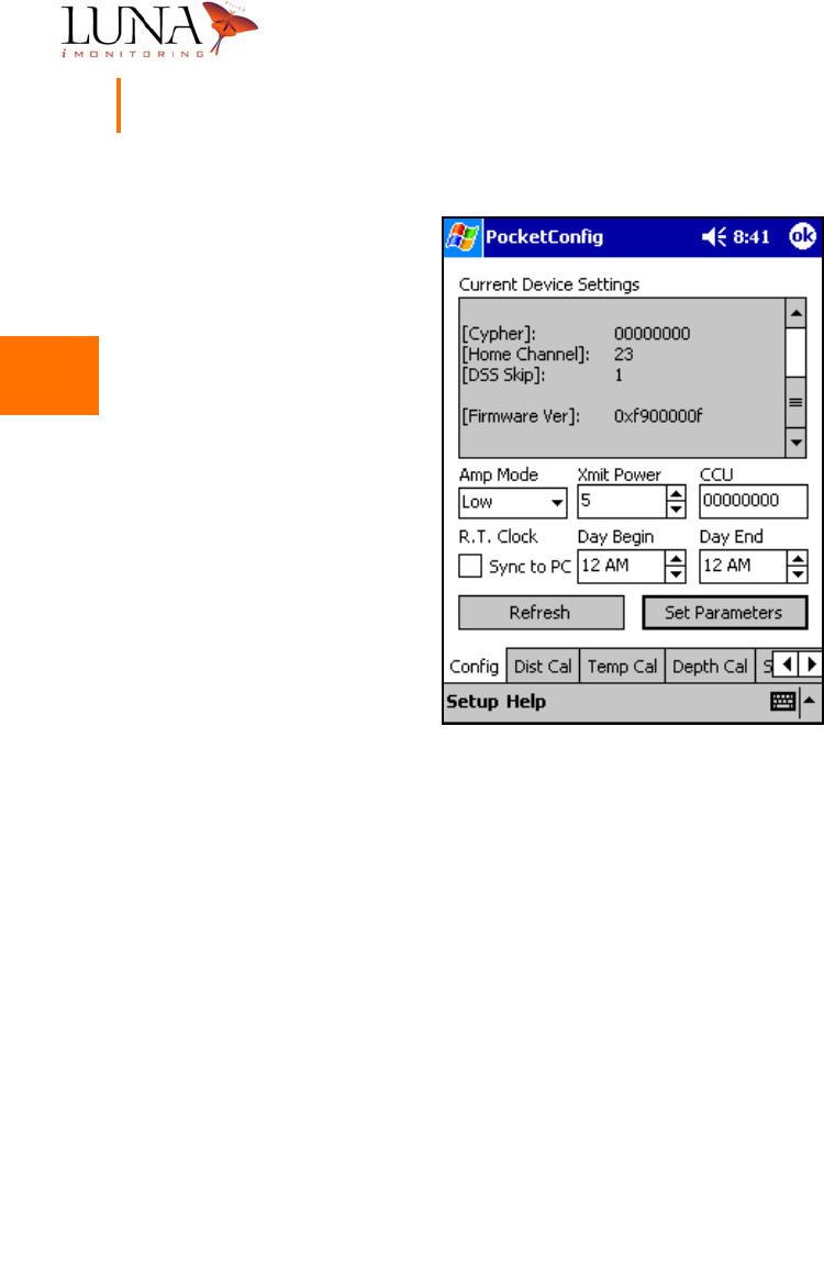
The Current Device Settings window provides other valuable information that is
accessible using the scroll bar. Figure 3-11 below shows the Current Device
Settings window for an iTLM-1 when scrolled down to reveal additional
parameters. This other information includes:
•the device serial number;
•a 4-byte encryption key, called the cypher, which must be the same
for all devices in a network;
•the home channel that the device waits on when there is no activity,
(when active the device scans all channels, 0-52);
•the modulus through the scanning sequence, called the DSS skip,
that can create additional sequences and must be the same for all
devices in a network, (usually set to 1);
•the version number of the device’s firmware.
3
3
3
3
3
3
3
3
3
3
3
3
3
3
26 Chapter 3
WEMS Software
Figure 3-11. Current Device Settings Continuation Window for an
i
TLM-1.
Each device uses a different set of menus for configuring additional parameters.
To access these menus, select one of the tabs along the bottom of the screen.
Some menus are similar for all devices, and some menus are device-specific. All
devices have menus for configuration, uplink scheduling, updating firmware,
setting advanced parameters, and testing the device’s radio. The iCCU has a
status menu and an uplink menu, and sensor devices have calibration menus and
a data menu.

3
3
3
3
3
3
3
3
3
3
3
3
3
3
Oil & Gas Wireless Enabled Monitoring System 27
Installer’s Guide
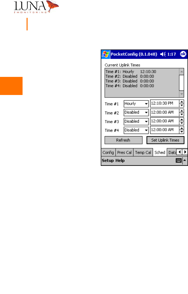
Uplink Scheduling Menu
The WEMS devices run autonomously according to the uplink schedule set in the
uplink scheduling menu. Sensors uplink to an iCCU, and an iCCU uplinks to a
computer via satellite. To access this menu, select the Sched tab as shown in
Figure 3-12 below. The software allows for four time schedules. For each time
schedule, the software allows three pull-down options - Enabled, Disabled, or
Hourly. In the Enabled mode, the device uplinks once daily at the time specified.
In the Hourly mode, the device uplinks every hour at the minute/second specified.
Normally, Hourly mode is only used for testing purposes. To change the time,
click on the desired field, (hour, minute, second, AM/PM), and use the up/down
arrows to change the field. Once the desired schedules and times are entered,
hit Set Uplink Times to accept the changes.
Sensor devices must uplink to an iCCU at specific time intervals when the iCCU
accepts data uplinks. The iCCU is active for one minute every ten minutes
“on the tens” of every hour. In other words, the iCCU is active from
00 min. 00 sec. after the hour to 01 min. 00 sec. after the hour; from
10 min. 00 sec. after the hour to 11 min. 00 sec. after the hour; from
20 min. 00 sec. after the hour to 21 min. 00 sec. after the hour; etc. Therefore,
synchronizing the real-time clocks on all devices and properly scheduling the uplink
times on sensor devices are very important.
When setting the uplink time on a sensor device, keep in mind that, over time,
the real-time clock may drift out of synchronization by a few seconds. Therefore,
do not select an uplink time that is too close to the beginning or end of the uplink
time window. Choose a value for the seconds field that falls between 15 and 45
seconds as in the example in Figure 3-12. Also, if the iCCU is linked to several
sensor devices, space the uplink times for each device about five seconds apart
to keep two devices from uplinking at the same time.
3
3
3
3
3
3
3
3
3
3
3
3
3
3
28 Chapter 3
WEMS Software
Figure 3-12. Uplink Scheduling Menu for an
i
WPM-T.
3
3
3
3
3
3
3
3
3
3
3
3
3
3
Oil & Gas Wireless Enabled Monitoring System 29
Installer’s Guide
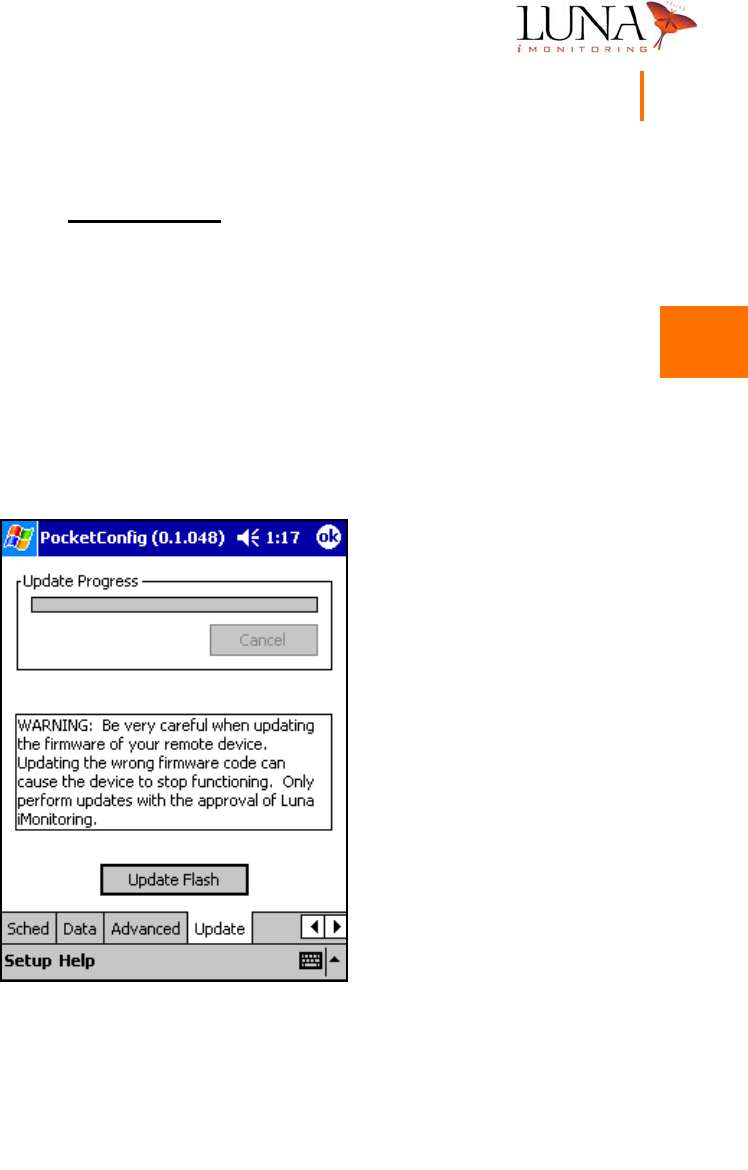
Update Flash Menu
The update flash menu permanently updates the firmware in a device
and should only be performed with the approval of Luna iMonitoring.
When firmware updates are needed, Luna iMonitoring will provide firmware
updates along with instructions on the type of devices to be updated. To open
the update flash menu, select the Update tab as shown in Figure 3-13 below.
Always verify that the proper device is selected for updates. Hit the
Update Flash button to begin the update process. The progress bar shows the
update progress. Always test the operation of the device thoroughly after
performing firmware updates.
Figure 3-13. Firmware Update Menu.
3
3
3
3
3
3
3
3
3
3
3
3
3
3
30 Chapter 3
WEMS Software
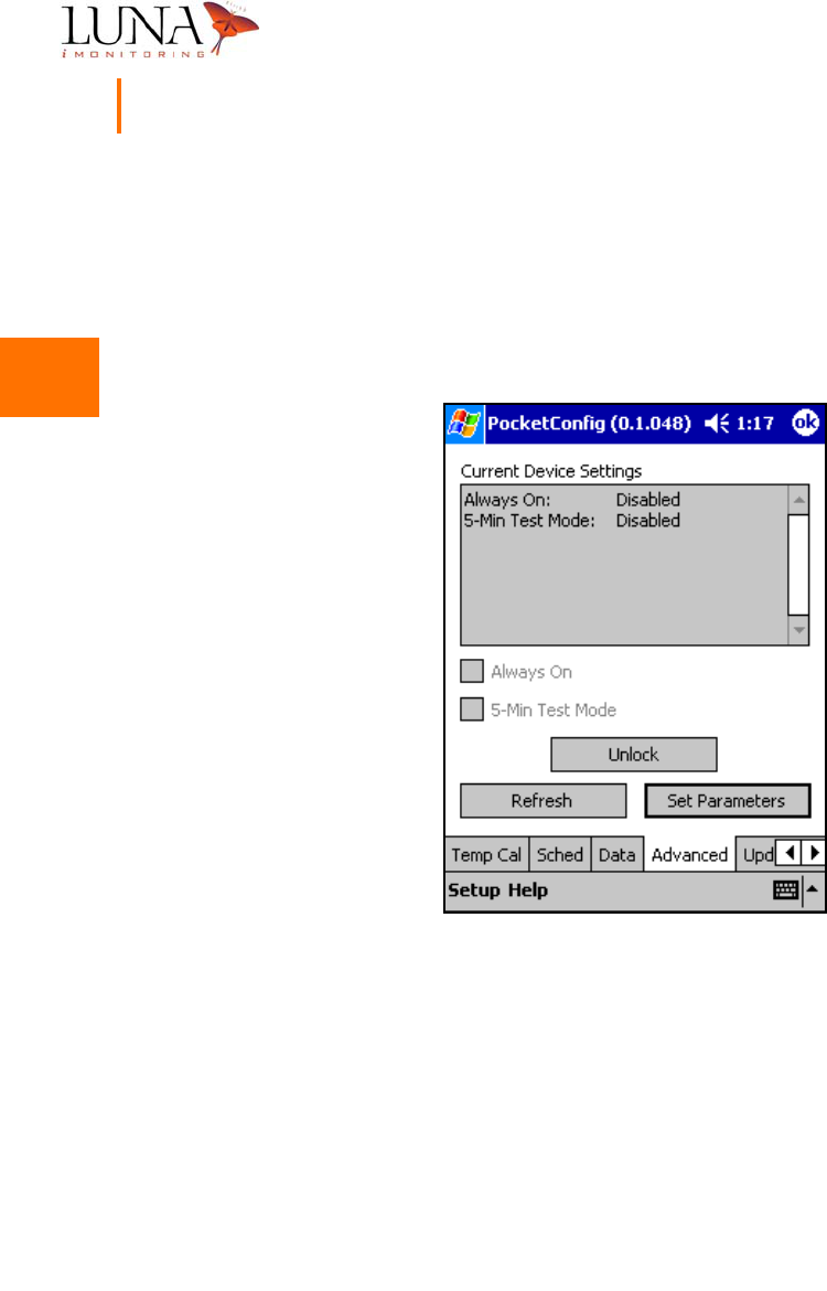
Advanced Parameters Menu
Figure 3-14 below shows the advanced parameters menu. This menu is password
protected, and is used by Luna iMonitoring Technical Support for testing. Under
normal operating conditions, the Always On mode and 5-Min. Test mode are
disabled.
Figure 3-14. Advanced Parameters Menu.
3
3
3
3
3
3
3
3
3
3
3
3
3
3
Oil & Gas Wireless Enabled Monitoring System 31
Installer’s Guide
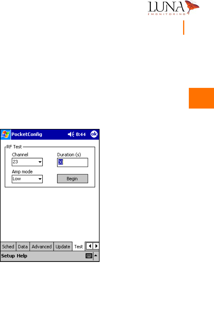
RF Test Menu
The RF Test menu shown in Figure 3-15 below performs a test on the device’s
radio. During the test, the radio broadcasts on specified channel using the settings
in the menu. To select the broadcast channel, choose a channel number from
0 to 52 from the pull-down list. Also, select an Amp Mode from the five options
in the pull down list - Off, Low, Medium, High, Cycle modes. Enter the length
of time in seconds for the test to run in the Duration field Once the correct test
settings are selected, hit the Begin button to perform the test.
Figure 3-15. RF Test Menu for an
i
CCU.
3
3
3
3
3
3
3
3
3
3
3
3
3
3
32 Chapter 3
WEMS Software
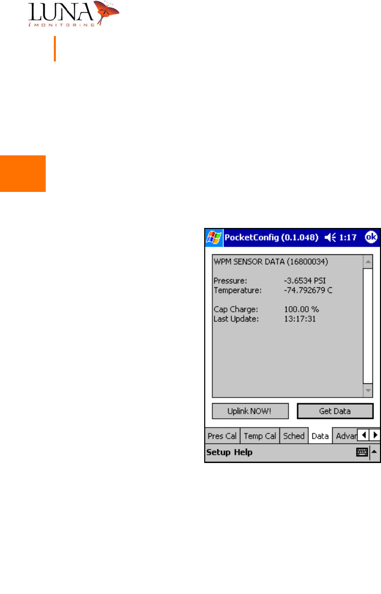
Sensor Data Menu
Figure 3-16 below shows the data menu for a sensor device, specifically an
iWPM-T, that is accessed by selecting the Data tab. To acquire new data points,
hit the Get Data button. The Sensor Data window indicates the type of sensor,
the serial number of the iCCU, the sensor data points taken, the battery charge
capacity, and the time that the Get Data was executed. To send the most recent
data points to the iCCU indicated by the serial number, hit the Uplink NOW!
button.
Figure 3-16.
i
WPM-T Data Menu.

3
3
3
3
3
3
3
3
3
3
3
3
3
3
Oil & Gas Wireless Enabled Monitoring System 33
Installer’s Guide
iCCU-Specific Menus
The iCCU tabs include menus for uplinking the iCCU to a computer and displaying
status information for the iCCU. Figure 3-17 shows the iCCU uplink menu that
is accessed by selecting the Uplink tab, and Figure 3-18 shows the iCCU status
menu that is accessed by selecting the Status tab.
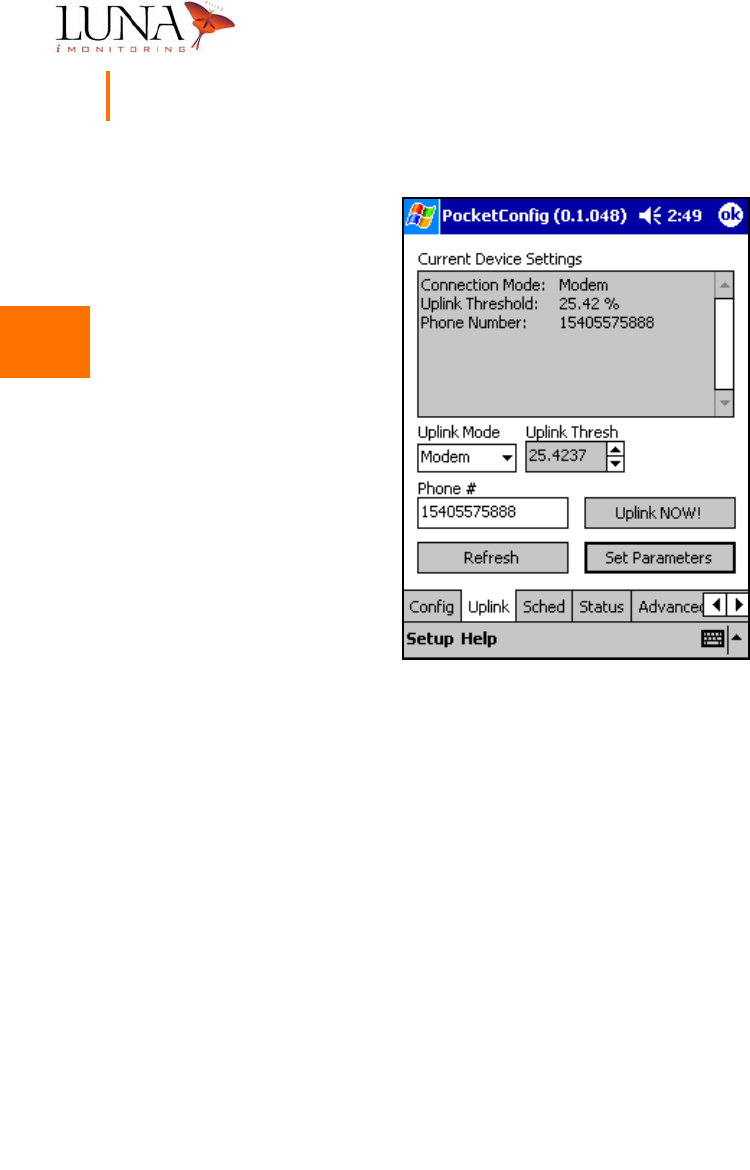
iCCU Uplink Menu
The iCCU uplink menu, shown in Figure 3-17 below, uplinks the iCCU to a
computer which downloads a data set. The Uplink Mode has two options - Modem,
which is the default, and Direct. In Modem mode, the iCCU uplinks to a satellite
which uses the Phone # to dial up the computer. To use the Direct mode, the
iCCU must be hardware-configured to connect directly to the serial port of a
computer using a special cable.
Before beginning an uplink, verify that the current battery charge is above the
preset Uplink Threshold. To begin an uplink, choose the Uplink Mode, enter the
Phone # for the computer, and hit the Set Parameters button. Once the
software accepts the parameters, hit the Uplink NOW! button to send the most
recent data points for each device uplinked to the iCCU.
3
3
3
3
3
3
3
3
3
3
3
3
3
3
34 Chapter 3
WEMS Software
Figure 3-17.
i
CCU Uplink Menu.
3
3
3
3
3
3
3
3
3
3
3
3
3
3
Oil & Gas Wireless Enabled Monitoring System 35
Installer’s Guide
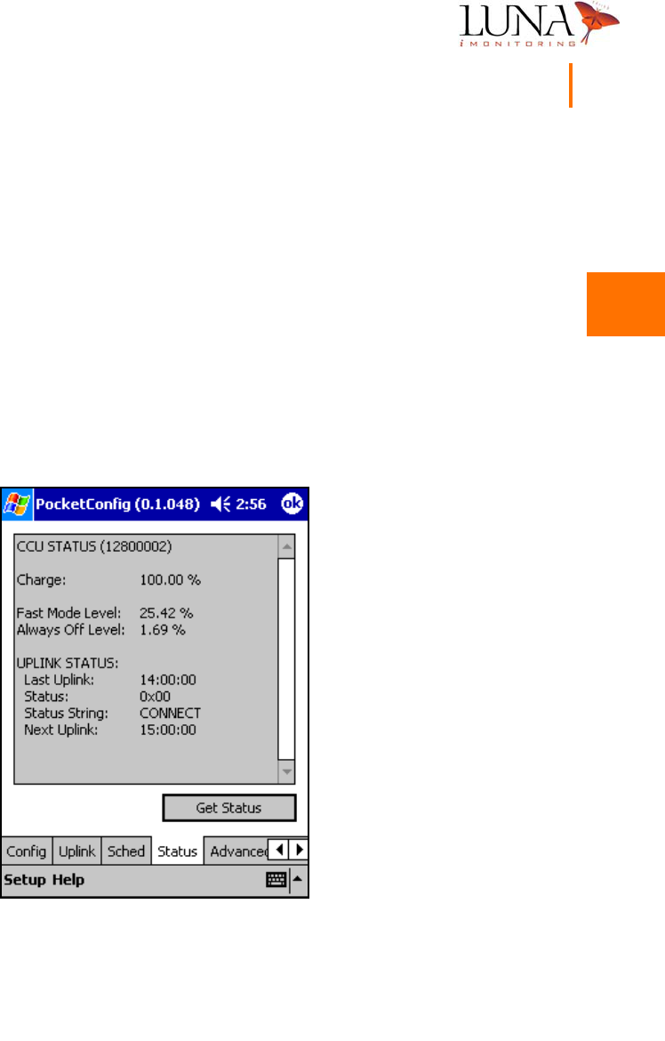
iCCU Status Menu
The iCCU status menu, shown in Figure 3-18 below, provides additional
information about the current status of the iCCU indicated by the serial number
in the CCU Status window. To get the current status, select the Status tab and
hit the Get Status button. The Charge field indicates the current charge of the
battery. Fast Mode Level is the battery charge level below which the device
switches from Fast Mode to Slow Mode, and the Always Off Level is the level
where the device shuts itself off.
Under Uplink Status, Last Uplink indicates the time of the most recent uplink to
the satellite, and Next Uplink indicates the scheduled time for the next uplink. A
Status code of 0x00 indicates that the last uplink was successful.
Figure 3-18.
i
CCU Status Menu.
3
3
3
3
3
3
3
3
3
3
3
3
3
3
36 Chapter 3
WEMS Software
iEFM-Specific Menus
The iEFM tabs include menus for calibrating the sensor and the gas element on
the iEFM device. Figure 3-19 below shows the menu for calibrating the sensor,
and Figure 3-20 on the following page shows the gas element calibration menu.
This section also discusses the iEFM sensor data window.
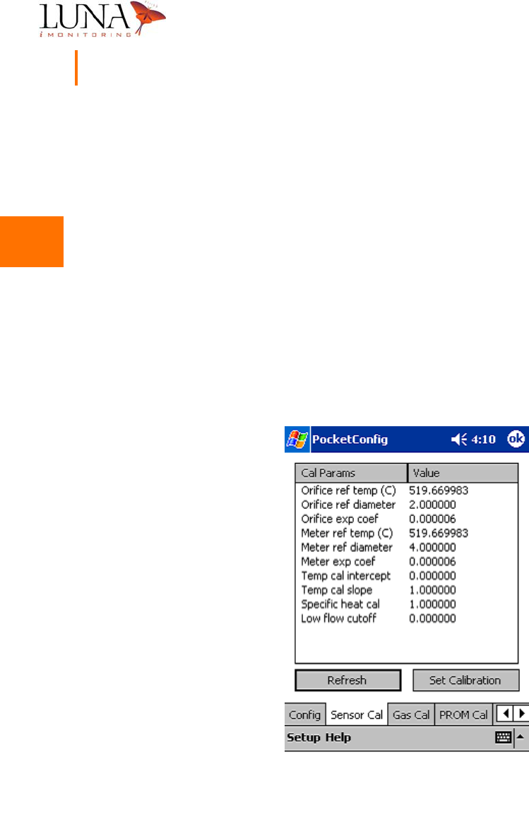
iEFM Sensor Calibration
The iEFM operation requires a number of parameters for valid measurements that
are entered using the sensor calibration menu shown in Figure 3-19 below, which
is accessed by selecting the Sensor Cal tab. The values for Temp cal intercept
and Temp cal slope are entered at the factory and are matched to the external
sensor that is supplied with the iEFM. The other parameters are dependant on
the process equipment to which the iEFM is attached.
Figure 3-19.
i
EFM Sensor Calibration Menu.
3
3
3
3
3
3
3
3
3
3
3
3
3
3
Oil & Gas Wireless Enabled Monitoring System 37
Installer’s Guide
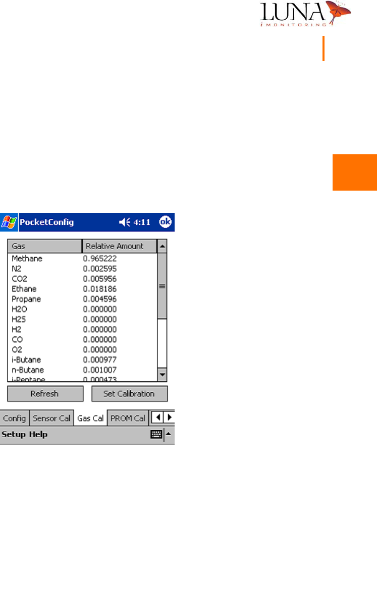
iEFM Gas Calibration
The process gas consists of multiple gas concentrations. The iEFM operation
requires that each gas element percentage of concentration be entered for valid
measurements. Enter the percentage values in decimal form using the gas
calibration menu shown in Figure 3-20 below, which is accessed by selecting the
Gas Cal tab. When all values are entered, hit the Set Calibration button to
accept the values.
Figure 3-20.
i
EFM Gas Calibration Menu.
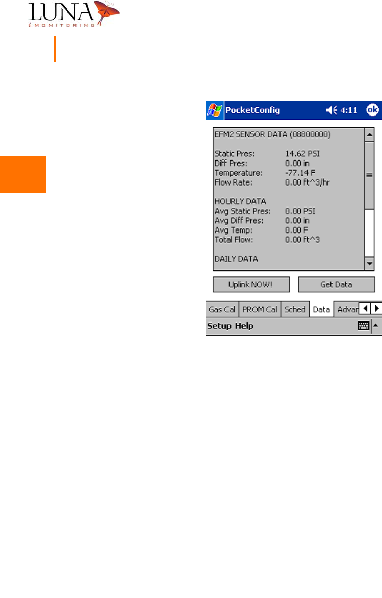
iEFM Sensor Data
The iEFM data may be viewed by selecting the Data tab at the bottom of the
screen which opens the sensor data window shown in Figure 3-21 below. The
first section of data reported is instantaneous data. The HOURLY DATA section
shows data averaged over the last 1-hour period, and the DAILY DATA gives the
data averaged over the last 24-hour period.
3
3
3
3
3
3
3
3
3
3
3
3
3
3
38 Chapter 3
WEMS Software
Figure 3-21.
i
EFM Sensor Data Window.

3
3
3
3
3
3
3
3
3
3
3
3
3
3
Oil & Gas Wireless Enabled Monitoring System 39
Installer’s Guide
iTLM-1-Specific Menus
The iTLM-1 tabs include menus for calibrating the temperature and tank level
sensors on the iTLM-1 device. Figure 3-23 below shows the menu for calibrating
the temperature sensor. Figures 3-22 and 3-24 on the following pages show the
distance and depth calibration menus, respectively, for the tank level sensor. Luna
iMonitoring performs the temperature and distance calibrations for the
temperature and tank level sensors, respectively, before shipping. The installer
performs the depth calibration for the tank level sensor.
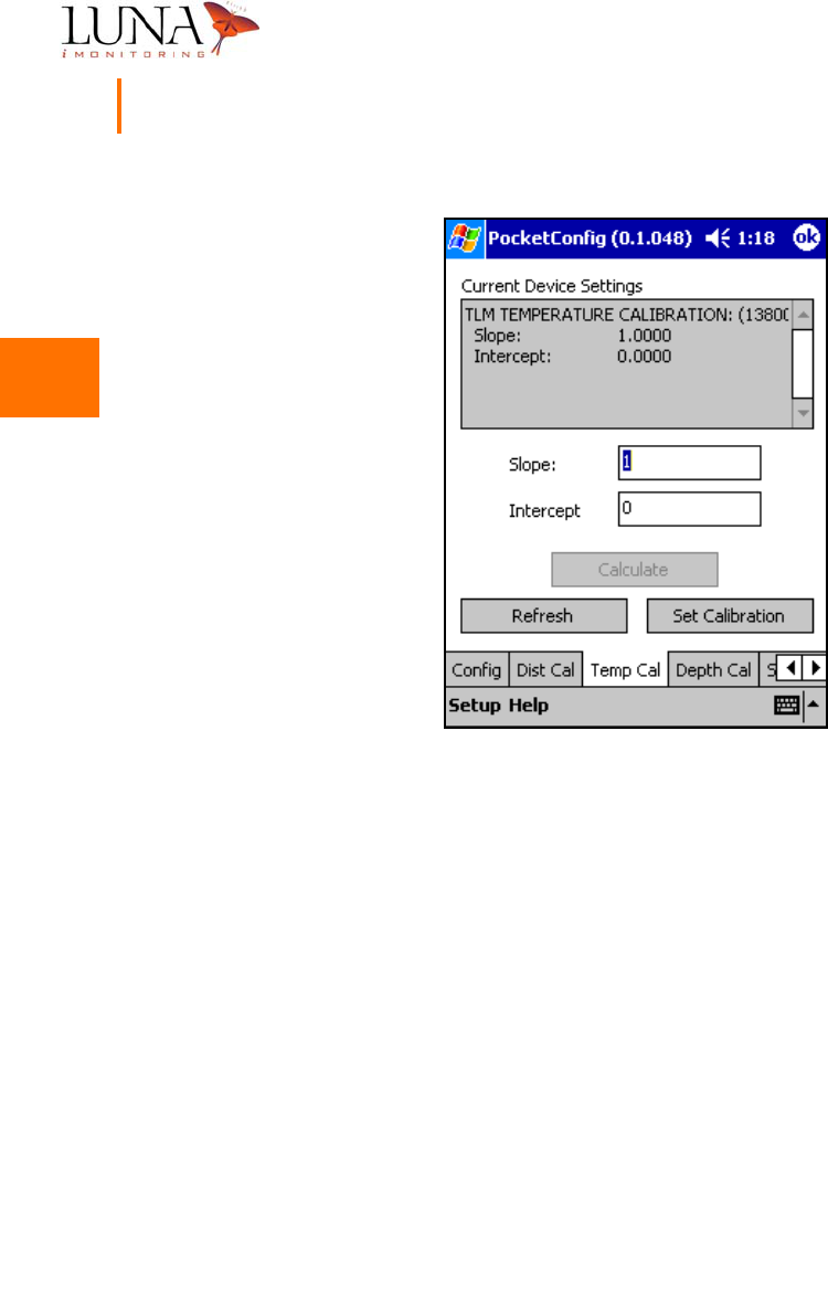
iTLM-1 Temperature Calibration
To set the temperature calibration parameters, select the Temp Cal tab at the
bottom of the screen to access the temperature calibration menu shown in
Figure 3-22 below. Enter the correct Slope and Intercept, and hit the Set
Calibration button. The iTLM-1 uses the temperature data to compensate for
the effects of temperature on the tank level measurement.
3
3
3
3
3
3
3
3
3
3
3
3
3
3
40 Chapter 3
WEMS Software
Figure 3-22.
i
TLM-1 Temperature Calibration Menu.
3
3
3
3
3
3
3
3
3
3
3
3
3
3
Oil & Gas Wireless Enabled Monitoring System 41
Installer’s Guide
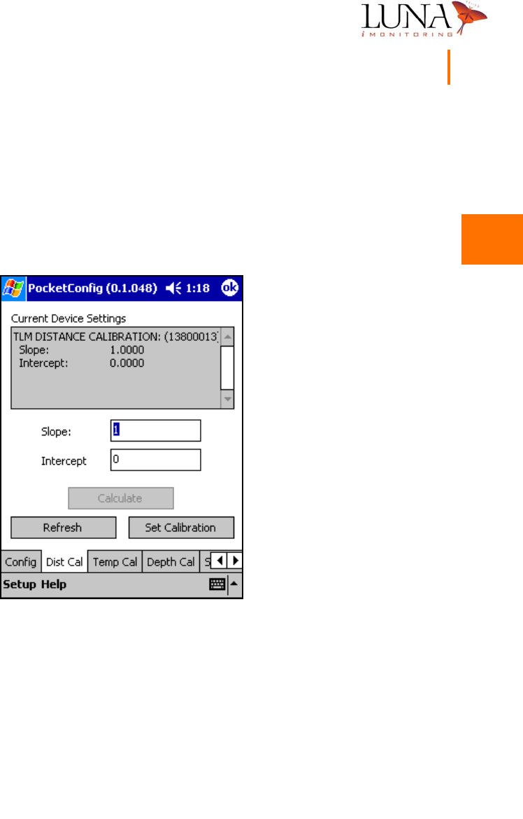
iTLM-1 Distance Calibration
Luna iMonitoring calibrates the iTLM-1 tank level sensor using a known distance
from the sensor to a surface in the lab. To set the distance calibration parameters,
select the Dist Cal tab at the bottom of the screen to access the distance calibration
menu shown in Figure 3-23 below. Enter the correct Slope and Intercept, and
hit the Set Calibration button.
Figure 3-23.
i
TLM-1 Distance Calibration Menu.
3
3
3
3
3
3
3
3
3
3
3
3
3
3
42 Chapter 3
WEMS Software
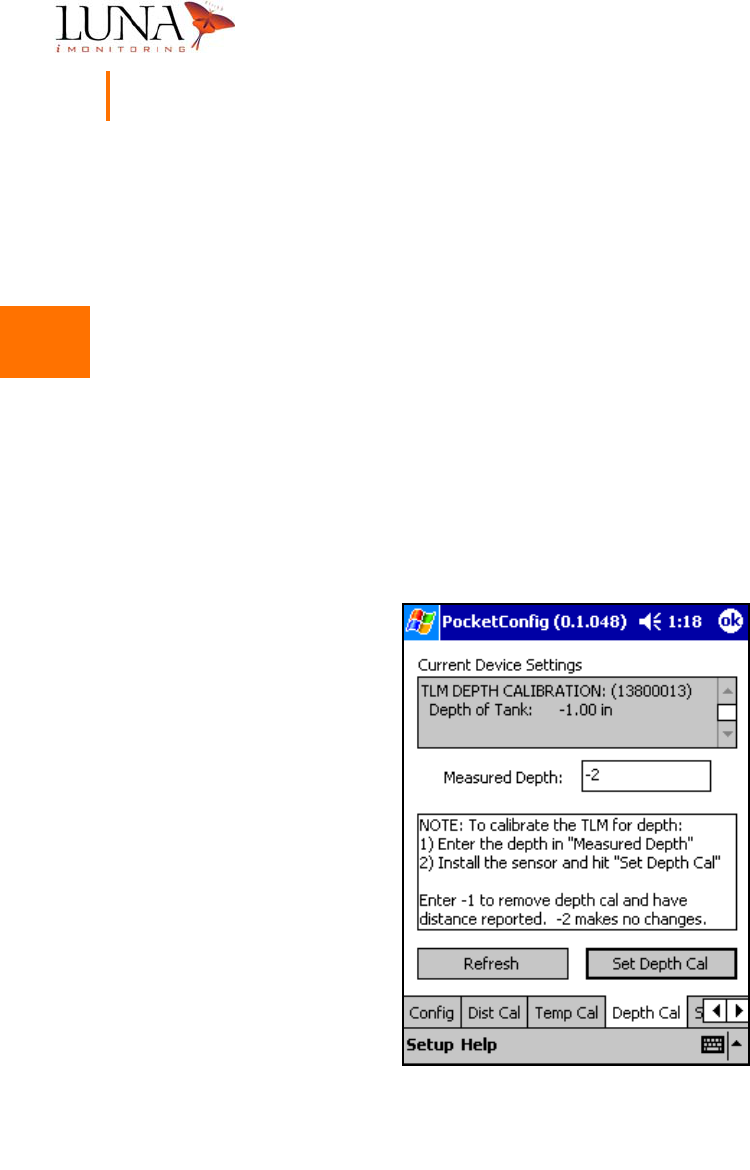
iTLM-1 Depth Calibration
The iTLM-1 depth calibration must be performed during the process of
installing the iTLM-1 sensor device on the tank.
At the time of the device installation, the iTLM-1 needs to know the exact depth
of the fluid in the tank to perform the depth calibration for the tank level sensor.
To set the depth calibration parameter, select the Depth Cal tab at the bottom
of the screen to access the depth calibration menu shown in Figure 3-24 below.
Enter the current depth of the fluid in the tank in inches in the Measured Depth
field, install the iTLM-1 sensor, and hit the Set Depth Cal button. Once the
depth calibration is complete, the value “-2” appears in the Measured Depth field
to block any inadvertant changes to the calibration parameters. Luna iMonitoring
personnel use the “-1” value, which removes the depth calibration and reports
distance. This is useful when performing the distance calibration.
Figure 3-24.
i
TLM-1 Depth Calibration Menu.
3
3
3
3
3
3
3
3
3
3
3
3
3
3
Oil & Gas Wireless Enabled Monitoring System 43
Installer’s Guide
iWPM-T-Specific Menus
The iWPM-T tabs include menus for calibrating the pressure and temperature
sensors on the iWPM-T device. Figure 3-25 below shows the menu for calibrating
the pressure sensor, and Figure 3-26 on the following page shows the temperature
sensor calibration menu. Luna iMonitoring calibrates all of the iWPM-T’s sensors
before shipping.
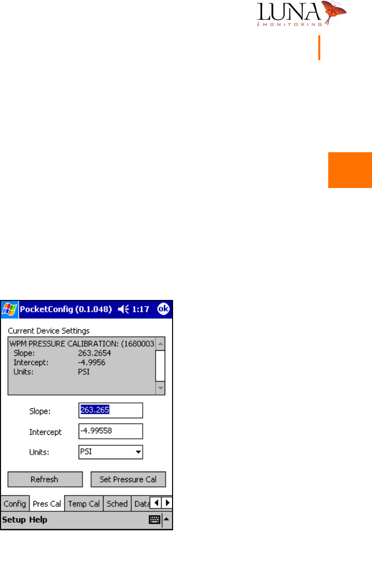
iWPM-T Pressure Sensor Calibration
To set the pressure calibration parameters, select the Pres Cal tab at the bottom
of the screen to access the pressure calibration menu shown in Figure 3-25 below.
Select the proper Units from the pull-down list. The choices for Units are millivolts,
PSI, mm Hg, kPa, and mBar. Enter the correct Slope and Intercept for the specified
units, and hit the Set Pressure Cal button.
Figure 3-25.
i
WPM-T Pressure Sensor Calibration Menu.
3
3
3
3
3
3
3
3
3
3
3
3
3
3
44 Chapter 3
WEMS Software
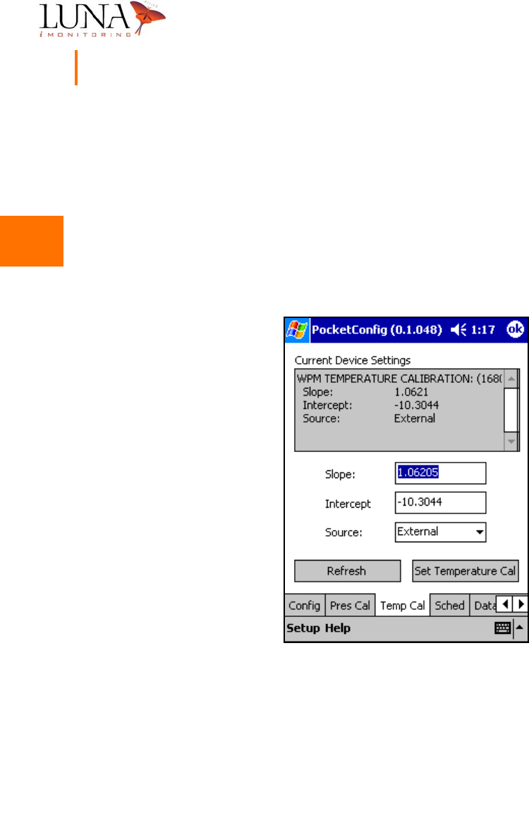
iWPM-T Temperature Calibration
To set the temperature calibration parameters, select the Temp Cal tab at the
bottom of the screen to access the temperature calibration menu shown in
Figure 3-26 below. Select the proper Source from the pull-down list. The choices
for Source are Internal for the iWPM-T, and External for the iWPM-T which has
an external temperature sensor. Enter the correct Slope and Intercept, and hit
the Set Temperature Cal button. The iWPM-T uses the temperature data to
compensate for the effects of temperature on the pressure measurement.
Figure 3-26.
i
WPM-T Temperature Sensor Calibration Menu.
3
3
3
3
3
3
3
3
3
3
3
3
3
3
Oil & Gas Wireless Enabled Monitoring System 45
Installer’s Guide
PocketDataViewer
The other software program on the SD Card is PocketDataViewer which
downloads a set of data points from a sensor device to the PocketPC®. Figure 3-31
below shows the main menu for the program. This program also includes the
same Setup Options and Help About windows as in PocketConfig which are
discussed in the following sections.
Setting the Default ReSync Time
The ReSync Time selected in the setup menu determines how long the software
waits for a response from a device. To access this menu, select the Setup tab
on the main menu, and hit the Options button shown in Figure 3-27 below.
Figure 3-27. Accessing the Setup Menu.
3
3
3
3
3
3
3
3
3
3
3
3
3
3
46 Chapter 3
WEMS Software
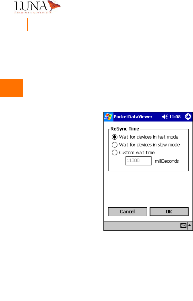
Figure 3-28 shows the setup menu and the ReSync Time options. If Wait for
devices in fast mode is selected, the software waits for 11 seconds to access a
device. Devices usually “wake up” every 10 seconds in Fast mode; therefore,
searching for 11 seconds should find the device. If Wait for devices in slow mode
is selected, the software waits for 121 seconds. The device may be in Slow mode
and will only “wake up” every 2 minutes. If Custom wait time is selected, enter
a wait time in milliseconds in the space provided. Once the proper mode is chosen,
hit the OK button to set the ReSync Time option.
Figure 3-28. ReSync Wait Time Selection Menu.
3
3
3
3
3
3
3
3
3
3
3
3
3
3
Oil & Gas Wireless Enabled Monitoring System 47
Installer’s Guide
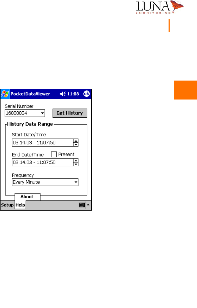
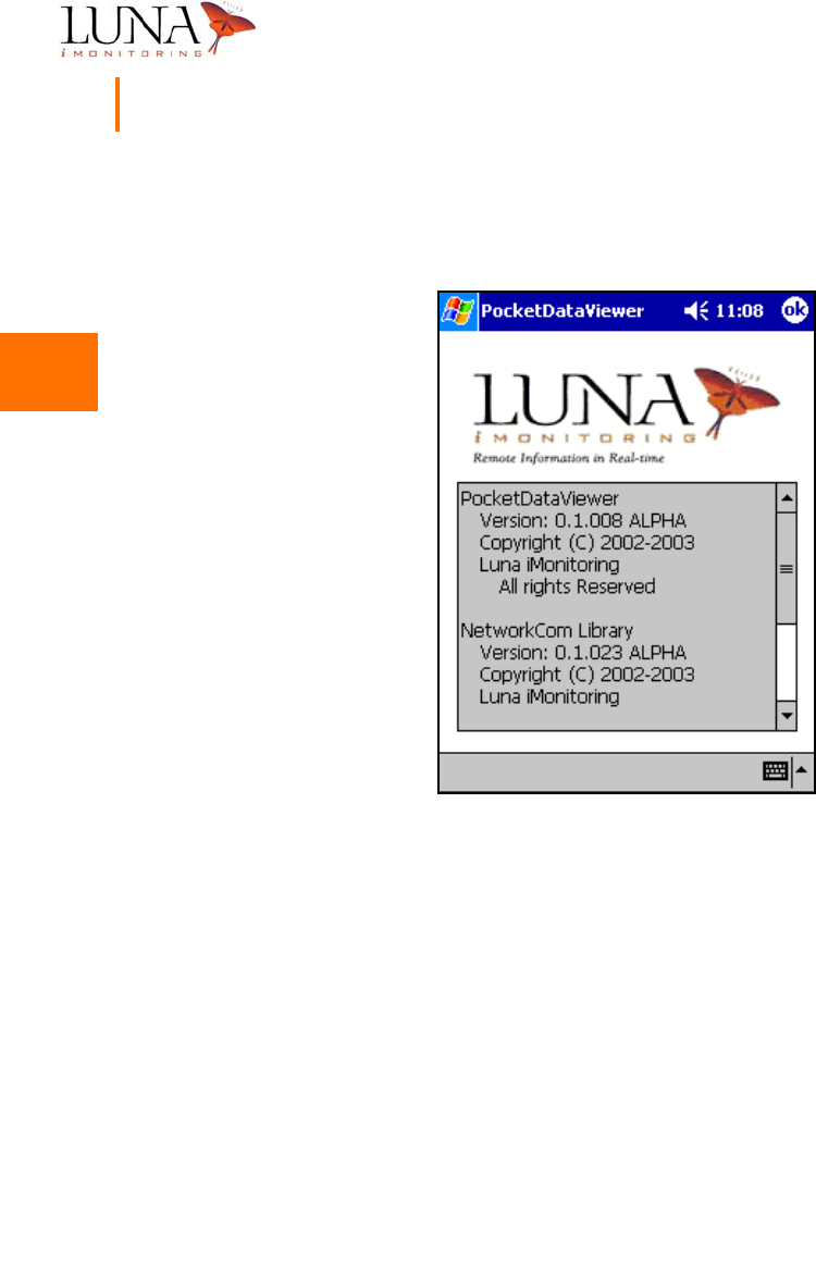
About PocketDataViewer
Luna iMonitoring includes information on each of its software programs that is
accessed by selecting the Help tab at the bottom of the screen and hitting the
About button as shown in Figure 3-29 below.
Figure 3-29. Accessing the About PocketDataViewer Menu.
3
3
3
3
3
3
3
3
3
3
3
3
3
3
48 Chapter 3
WEMS Software
This window provides copyright and version information on the program and
library software.
Figure 3-30. Detailed Information on PocketDataViewer.
3
3
3
3
3
3
3
3
3
3
3
3
3
3
Oil & Gas Wireless Enabled Monitoring System 49
Installer’s Guide
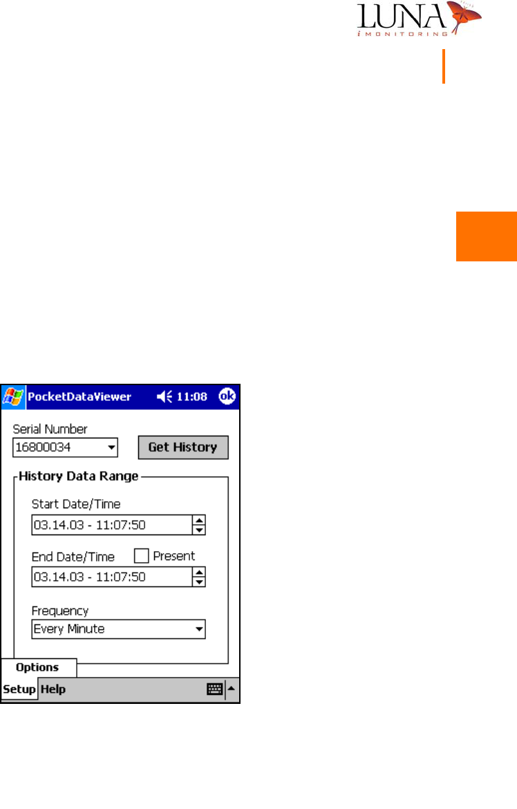
Selecting a Sensor Device
To select the sensor device from which to download data, enter its unique serial
number in the Serial Number field or select it from the pull-down list.
Note: this
program only recognizes sensor devices, not
i
CCU devices.
The Serial Number
field in this program functions the same as the Serial Number field in
PocketConfig. The program stores the ten most recently accessed serial numbers
in the pull-down list.
Figure 3-31.
PocketDataViewer
Main Menu.
3
3
3
3
3
3
3
3
3
3
3
3
3
3
50 Chapter 3
WEMS Software
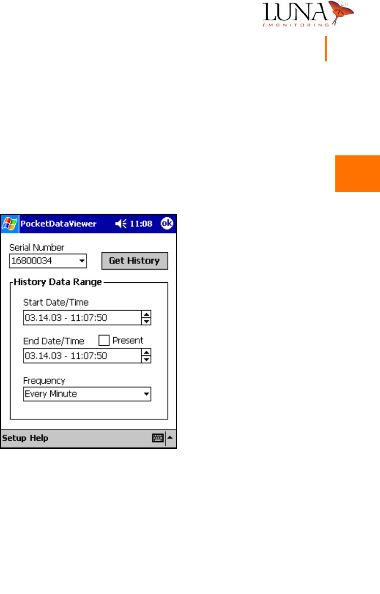
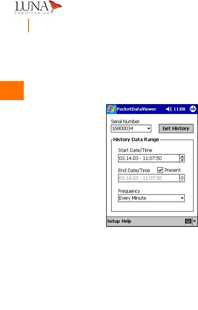
Selecting the History Data Range
By default, the Start Date/Time and End Date/Time are initially set to the current
time. To change a date or time field, select the appropriate field and change it
using the up/down arrow buttons to the right of the field. To “hard code” the
software to use the current date and time as the End Date/Time, select the Present
option as shown in Figure 3-32 below.
Figure 3-32. Selecting the End Date and Time.
3
3
3
3
3
3
3
3
3
3
3
3
3
3
Oil & Gas Wireless Enabled Monitoring System 51
Installer’s Guide
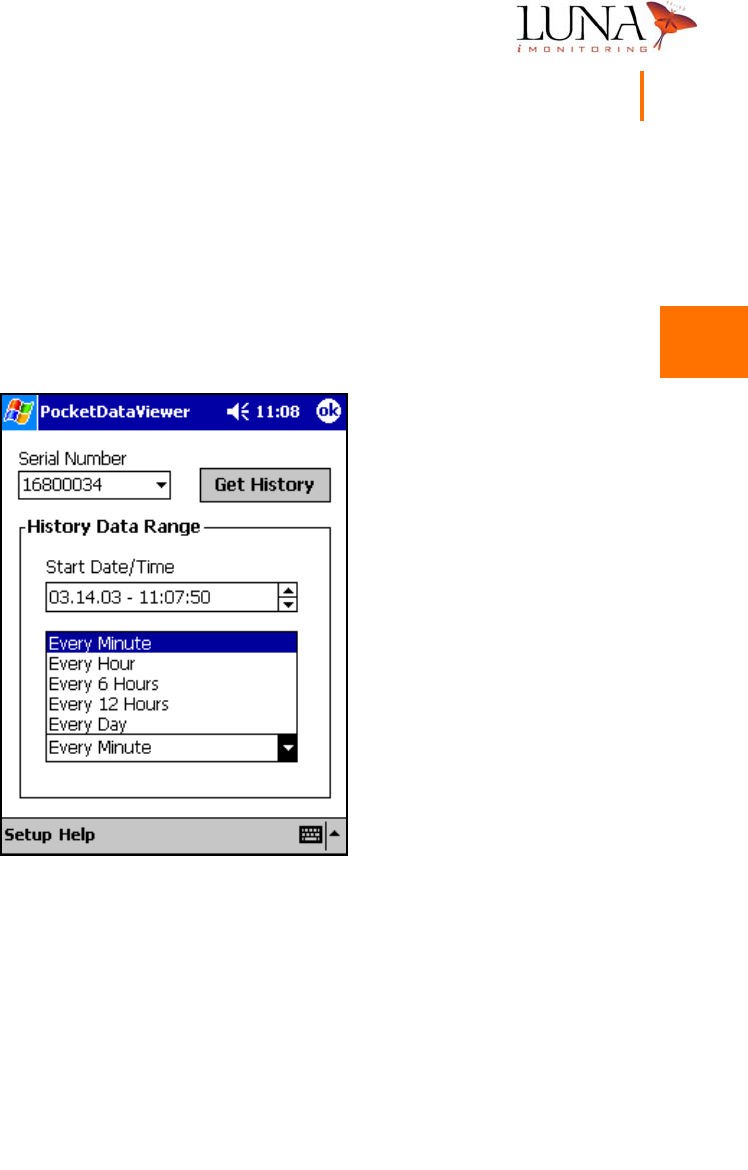
Selecting the Data Point Frequency
By default, sensor devices acquire and internally store data points every minute,
even though they may only uplink and transmit one set of data points per day.
PocketDataViewer provides access to all or part of these data points based on
the Frequency interval selected from the pull-down list shown below in
Figure 3-33.
Figure 3-33. Data Point Frequency Interval Options.
Once the Serial Number and History Data Range are selected, hit the Get History
button to download the data points and bring up the windows shown in the
following two Sections.
Note: the software issues a warning if the number of
data sets requested is greater than 100.
3
3
3
3
3
3
3
3
3
3
3
3
3
3
52 Chapter 3
WEMS Software
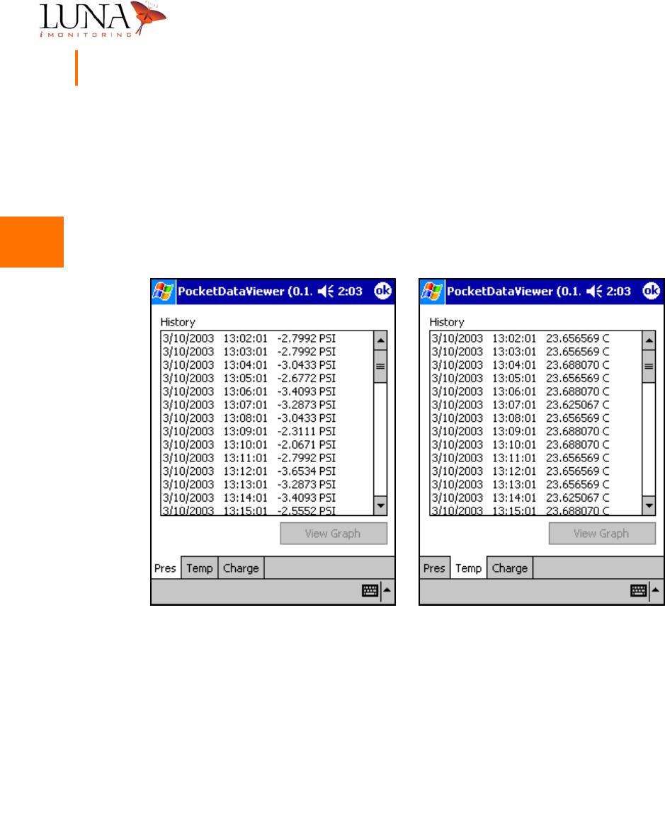
Sensor Data History
The next two sections use history data from an iWPM-T sensor device; however,
other sensor devices have similar displays. The History window has tabs for each
of the sensor data measurements and the battery charge capacity. Figure 3-34
below shows the sensor data measurements for an iWPM-T which has pressure
and temperature sensors. The iTLM-1 has depth and temperature sensors.
Figure 3-34. (a) Pressure and (b) Temperature Sensor Data History for an
i
WPM-T.
In every data history window, column 1 contains the date, column 2 contains the
time, and column 3 contains the data point and units. Use the scroll bar at the
right of the window to scroll through the entire data range.
In a later release of the software, the View Graph option will display a graph
of the entire data range.
(a) (b)
3
3
3
3
3
3
3
3
3
3
3
3
3
3
Oil & Gas Wireless Enabled Monitoring System 53
Installer’s Guide
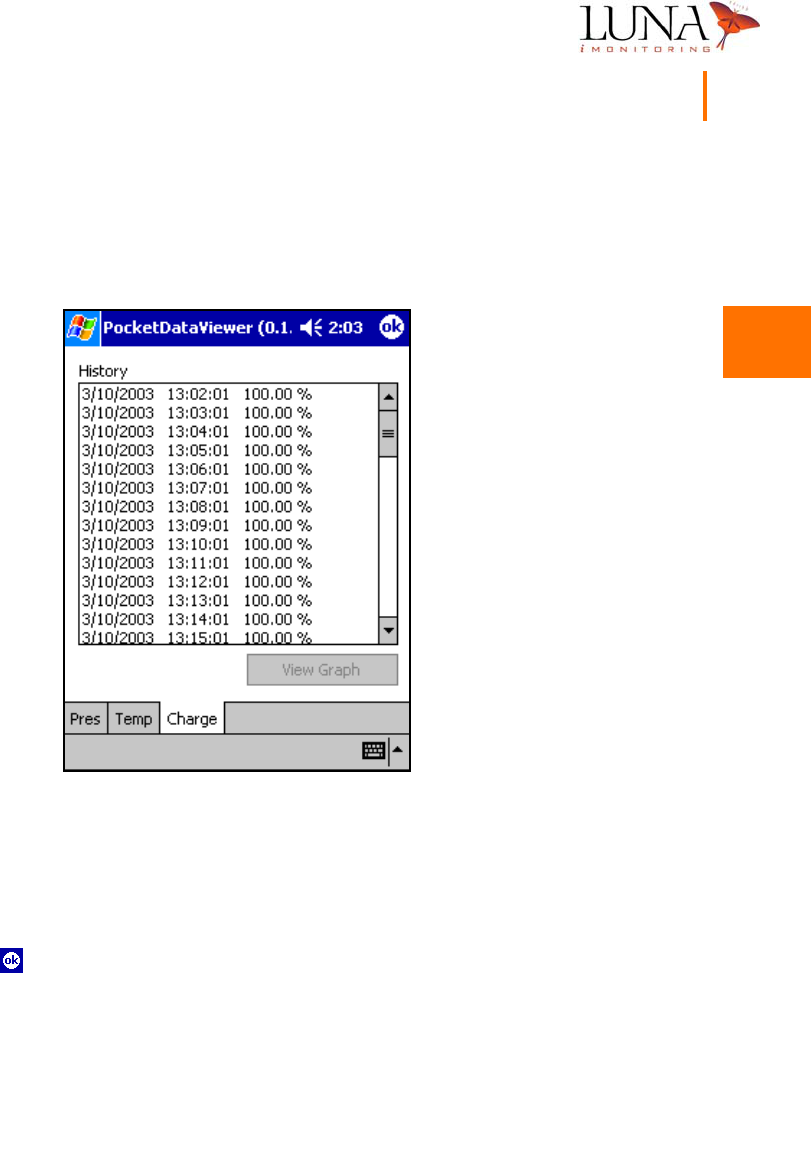
Battery Charge History
Figure 3-35 below shows the battery charge capacity history for an iWPM-T sensor
device, but this window is the same for all sensor devices.
Figure 3-35. Battery Charge Capacity History for an
i
WPM-T.
Exiting the Software
To safely exit either software program, PocketConfig or PocketDataViewer,
simply hit the button in the top right corner of the screen.

3
3
3
3
3
3
3
3
3
3
3
3
3
3
54 Chapter 3
WEMS Software

A
A
A
A
A
A
A
A
A
A
A
A
A
A
55
Appendix A
Specifications
Description Specification
iCCU - Concentration & Communications Unit
Dimensions:
Enclosure
Solar Panel
11.5” x 8.0” x 5.0”
10.0” x 9.0” x .5”
LAN Transmit/ Receive Frequency 902 to 928 MHz (customizable)
LAN Output Power TBD, conducted
LAN Communications Protocol Proprietary FHSS, per FCC Part 15.247
LAN Data Rate 4800 bps
WAN Options Simplex or duplex sat com (released),
Cellular and land line (near future)
WAN Data Rate < 9.6 Kbps
Operational Temperature Range -40 to +55 oC
Radio Link Range:
iCCU to Sensor
iCCU to PocketPC®
2500 feet; typical, line of sight
500 feet; typical, line of sight
FCC
LAN
WAN
CFR 47 Part 15
CFR 47 Part 25

A
A
A
A
A
A
A
A
A
A
A
A
A
A
56 Appendix A
Specifications
iCFR - Compact Flash Radio
Transmit/Receive Frequency 902 to 928 MHz (customizable)
Form Factor Type I compact flash
Power Supply 3 to 5V (from host unit)
Power Consumption:
Transmit
Receive
25mA max
11.8 mA
Protocol Propriety FHSS, per FCC Part 15.247
Receive Sensitivity -97 to -110 dBm (depending on data rate)
Output Power TBD, conducted
Modulation FSK
Data Rate Up to 76 Kbps
Antenna Internal
FCC CFR 47 Part 15
Description Specification

A
A
A
A
A
A
A
A
A
A
A
A
A
A
Oil & Gas Wireless Enabled Monitoring System 57
Installer’s Guide
iEFM - Electronic Flow Monitor*
Operational Temperature Range -40 to +60oC
Output Power:
Omni Antenna
Yagi Antenna
17.7 dBm max, conducted
13.4 dBm max, conducted
Radio Link Range:
Sensor to iCCU
Sensor to PocketPC®
2500 feet; typical, line of sight
500 feet; typical, line of sight
UL Intrinsically Safe for Class I, Division 1, Groups C and
D per UL-913
FCC CFR 47 Part 15,
CFR 47 Part 18 (ultrasonic transducer)
*For additional specifications, see Honeywell specifications for MXA145 Flow Transmitter.
Description Specification

A
A
A
A
A
A
A
A
A
A
A
A
A
A
58 Appendix A
Specifications
iTLM-1 - Tank Level Monitor
Fluid Level Range 12 to 144 inches
Resolution 0.1 inches
Accuracy ± 0.5 inches
Repeatability ± 0.2 inches at fixed temperature
Mounting 1-1/2 inch NPT, up to 0.25 inch thickness
Mounting Angle 5o maximum
Temperature Compensated Yes
Operational Temperature Range -40 to +60oC
Output Power:
Omni Antenna
Yagi Antenna
17.7 dBm max, conducted
13.4 dBm max, conducted
Radio Link Range:
Sensor to iCCU
Sensor to PocketPC®
2500 feet; typical, line of sight
500 feet; typical, line of sight
UL Intrinsically Safe for Class I, Division 1, Groups C and
D per UL-913
FCC CFR 47 Part 15,
CFR 47 Part 18 (ultrasonic transducer)
Description Specification

A
A
A
A
A
A
A
A
A
A
A
A
A
A
Oil & Gas Wireless Enabled Monitoring System 59
Installer’s Guide
iWPM-T - Wireless Pressure Monitor
Pressure Range 0 to 1400 psig
Resolution 10 psig
Accuracy ± 30 psig
Overpressure 2000 psig
Temperature Compensated Yes
Mounting 1/4 inch NPT
Operational Temperature Range -40 to +60oC
Output Power:
Omni Antenna
Yagi Antenna
17.7 dBm max, conducted
13.4 dBm max, conducted
Radio Link Range:
Sensor to iCCU
Sensor to PocketPC®
2500 feet; typical, line of sight
500 feet; typical, line of sight
UL Intrinsically Safe for Class I, Division 1, Groups C and
D per UL-913
FCC CFR 47 Part 15
Description Specification

A
A
A
A
A
A
A
A
A
A
A
A
A
A
60 Appendix A
Specifications

B
B
B
B
B
B
B
B
B
B
B
B
B
B
61
Appendix B
Technical Support
If you experience any problems using the Oil and Gas Wireless Enabled Monitoring
System, please contact Luna iMonitoring Technical Support at
2903 Commerce Street, Suite A
Blacksburg, VA 24060 USA
Voice: 540-557-5880
FAX: 540-951-0760
Email: solutions@lunaimonitoring.com
Web: www.lunaimonitoring.com

B
B
B
B
B
B
B
B
B
B
B
B
B
B
62 Appendix B
Technical Support
C
C
C
C
C
C
C
C
C
C
C
C
C
C
63
Appendix C
Using the Charge Cable
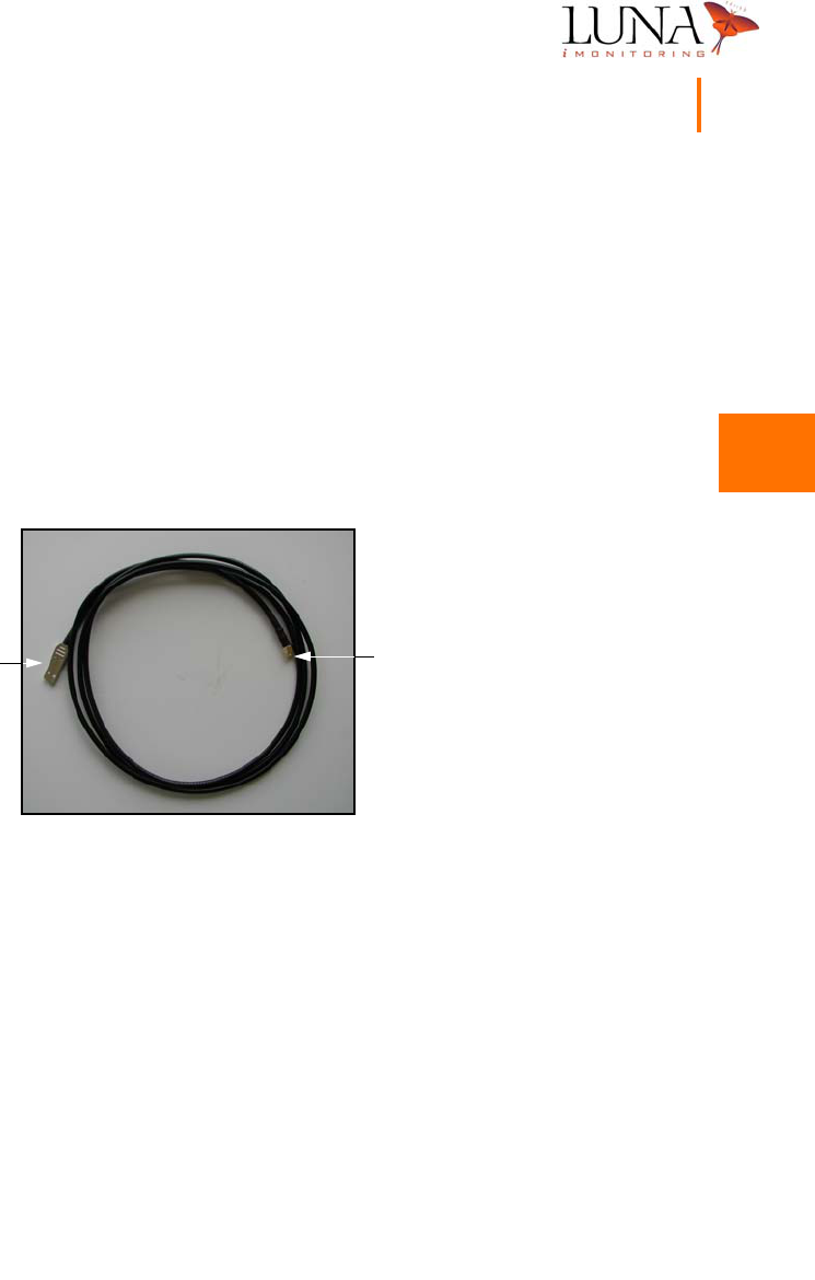
Figure C-1. WEMS Charge Cable.
Luna iMonitoring provides a device Charge Cable, shown in Figure C-1 above,
with most Beta Test versions of the Wireless Enabled Monitoring System. The
Charge Cable is for use in a lab setting and is not tested or approved
for use in hazardous environments. The Charge Cable has an SMA connector
at one end and a USB connector at the other end. The SMA connector plugs
into the SMA antenna connector on the WEMS device being tested. The antenna
on each WEMS device simply screws off of the SMA connector. The USB connector
plugs into the USB port of any computer. The SMA connector serves as an antenna
connection as well as a power connection. Therefore, the device receives power
from the USB port on the computer when the computer is on. Even though the
antenna is disconnected, the device can still receive and transmit radio signals in
a lab setting.
SMA
Connector
USB
Connector

C
C
C
C
C
C
C
C
C
C
C
C
C
C
64 Appendix C
Using the Charge Cable
The Charge Cable serves two purposes:
1It quickly charges the battery to full capacity.
2It maintains a full charge on the battery in a lab setting where the solar
panels can not charge the battery.